EP4113161A1 - Kamera - Google Patents
Kamera Download PDFInfo
- Publication number
- EP4113161A1 EP4113161A1 EP22177874.9A EP22177874A EP4113161A1 EP 4113161 A1 EP4113161 A1 EP 4113161A1 EP 22177874 A EP22177874 A EP 22177874A EP 4113161 A1 EP4113161 A1 EP 4113161A1
- Authority
- EP
- European Patent Office
- Prior art keywords
- lighting
- camera
- switching regulator
- unit
- lighting unit
- Prior art date
- Legal status (The legal status is an assumption and is not a legal conclusion. Google has not performed a legal analysis and makes no representation as to the accuracy of the status listed.)
- Granted
Links
Images
Classifications
-
- G—PHYSICS
- G01—MEASURING; TESTING
- G01S—RADIO DIRECTION-FINDING; RADIO NAVIGATION; DETERMINING DISTANCE OR VELOCITY BY USE OF RADIO WAVES; LOCATING OR PRESENCE-DETECTING BY USE OF THE REFLECTION OR RERADIATION OF RADIO WAVES; ANALOGOUS ARRANGEMENTS USING OTHER WAVES
- G01S7/00—Details of systems according to groups G01S13/00, G01S15/00, G01S17/00
- G01S7/48—Details of systems according to groups G01S13/00, G01S15/00, G01S17/00 of systems according to group G01S17/00
- G01S7/483—Details of pulse systems
-
- G—PHYSICS
- G01—MEASURING; TESTING
- G01S—RADIO DIRECTION-FINDING; RADIO NAVIGATION; DETERMINING DISTANCE OR VELOCITY BY USE OF RADIO WAVES; LOCATING OR PRESENCE-DETECTING BY USE OF THE REFLECTION OR RERADIATION OF RADIO WAVES; ANALOGOUS ARRANGEMENTS USING OTHER WAVES
- G01S17/00—Systems using the reflection or reradiation of electromagnetic waves other than radio waves, e.g. lidar systems
- G01S17/88—Lidar systems specially adapted for specific applications
- G01S17/89—Lidar systems specially adapted for specific applications for mapping or imaging
- G01S17/894—Three-dimensional [3D] imaging with simultaneous measurement of time-of-flight at a two-dimensional [2D] array of receiver pixels, e.g. time-of-flight cameras or flash lidar
-
- G—PHYSICS
- G01—MEASURING; TESTING
- G01S—RADIO DIRECTION-FINDING; RADIO NAVIGATION; DETERMINING DISTANCE OR VELOCITY BY USE OF RADIO WAVES; LOCATING OR PRESENCE-DETECTING BY USE OF THE REFLECTION OR RERADIATION OF RADIO WAVES; ANALOGOUS ARRANGEMENTS USING OTHER WAVES
- G01S17/00—Systems using the reflection or reradiation of electromagnetic waves other than radio waves, e.g. lidar systems
- G01S17/02—Systems using the reflection of electromagnetic waves other than radio waves
- G01S17/06—Systems determining position data of a target
- G01S17/42—Simultaneous measurement of distance and other co-ordinates
-
- G—PHYSICS
- G01—MEASURING; TESTING
- G01S—RADIO DIRECTION-FINDING; RADIO NAVIGATION; DETERMINING DISTANCE OR VELOCITY BY USE OF RADIO WAVES; LOCATING OR PRESENCE-DETECTING BY USE OF THE REFLECTION OR RERADIATION OF RADIO WAVES; ANALOGOUS ARRANGEMENTS USING OTHER WAVES
- G01S17/00—Systems using the reflection or reradiation of electromagnetic waves other than radio waves, e.g. lidar systems
- G01S17/88—Lidar systems specially adapted for specific applications
- G01S17/93—Lidar systems specially adapted for specific applications for anti-collision purposes
- G01S17/931—Lidar systems specially adapted for specific applications for anti-collision purposes of land vehicles
-
- H—ELECTRICITY
- H04—ELECTRIC COMMUNICATION TECHNIQUE
- H04N—PICTORIAL COMMUNICATION, e.g. TELEVISION
- H04N13/00—Stereoscopic video systems; Multi-view video systems; Details thereof
- H04N13/20—Image signal generators
- H04N13/204—Image signal generators using stereoscopic image cameras
- H04N13/207—Image signal generators using stereoscopic image cameras using a single two-dimensional [2D] image sensor
-
- H—ELECTRICITY
- H04—ELECTRIC COMMUNICATION TECHNIQUE
- H04N—PICTORIAL COMMUNICATION, e.g. TELEVISION
- H04N13/00—Stereoscopic video systems; Multi-view video systems; Details thereof
- H04N13/20—Image signal generators
- H04N13/296—Synchronisation thereof; Control thereof
-
- H—ELECTRICITY
- H04—ELECTRIC COMMUNICATION TECHNIQUE
- H04N—PICTORIAL COMMUNICATION, e.g. TELEVISION
- H04N23/00—Cameras or camera modules comprising electronic image sensors; Control thereof
- H04N23/56—Cameras or camera modules comprising electronic image sensors; Control thereof provided with illuminating means
-
- H—ELECTRICITY
- H04—ELECTRIC COMMUNICATION TECHNIQUE
- H04N—PICTORIAL COMMUNICATION, e.g. TELEVISION
- H04N23/00—Cameras or camera modules comprising electronic image sensors; Control thereof
- H04N23/70—Circuitry for compensating brightness variation in the scene
- H04N23/74—Circuitry for compensating brightness variation in the scene by influencing the scene brightness using illuminating means
Definitions
- the invention relates to a camera, in particular a 3D time-of-flight camera, according to claim 1.
- Such a camera preferably works according to a scanning principle, in which a light beam is emitted as a light pulse into a surveillance area and the light beam reflected by an object is received again in order to then evaluate the received signal electronically. This enables the camera to measure a distance and thereby obtains depth information.
- a 3D image, a distance image or a depth map is generated from the captured three-dimensional image data with distance values for the individual pixels.
- Various methods are known for determining the depth information.
- the time of flight of light is often measured using a known phase or pulse method in order to determine the distance from a touched object. These methods are also called TOF (Time-Of-Flight) or LIDAR (Light Detection And Ranging).
- 3D image data obtained in this way can be used in automation technology to control moving actuators such as robots or vehicles.
- the 3D image data is used, for example, to support a driver or to enable autonomous navigation, among other things to recognize obstacles, avoid collisions or to facilitate the loading and unloading of transport goods including boxes, pallets, containers or trailers.
- switching regulators In order to control the energy supply of the lighting of the 3D time-of-flight camera, switching regulators are used, which operate in a continuous mode (also called continuous current mode “CCM”) or in a discontinuous mode (also called discontinuous current mode “DCM”). can be operated.
- CCM continuous current mode
- DCM discontinuous current mode
- the switching regulator ensures that the lighting of the 3D time-of-flight camera is continuously supplied with power, even if the lighting of the 3D time-of-flight camera does not emit a light pulse.
- the switching controller is designed to supply the lighting of the 3D time-of-flight camera with power only for the emission of the light pulse and to be currentless outside of a lighting phase.
- the switching regulator has a poor response to sudden changes in load, resulting in losses in the measurement performance of the 3D time-of-flight camera.
- the camera according to the invention in particular a 3D time-of-flight camera, comprises a lighting unit that emits light pulses during a lighting phase, an image sensor that generates images from the light pulses reflected by an object, a switching controller that regulates the current to the lighting unit, the switching controller in a can be operated continuously and in a discontinuous mode, and a control unit which is designed to activate and deactivate the continuous mode of the switching regulator depending on the lighting phase of the lighting unit.
- control unit activates the continuous mode of the switching regulator before the lighting unit is switched on and deactivates the continuous mode of the switching regulator after the lighting unit is switched off. In this way it is possible to provide the full current for the lighting unit at the beginning of the lighting phase, so that a constant lighting pattern can be achieved.
- control unit activates the discontinuous mode between two lighting phases of the lighting unit, as a result of which power loss due to the switching regulator is itself minimized, with no need to regulate the supply voltage of the switching regulator.
- the lighting phase of the lighting unit preferably consists of an envelope curve which is in the range from microseconds to milliseconds and envelops light pulses in the range from nanoseconds.
- the activation of the continuous mode of the switching regulator enables a fast illumination pattern of the 3D time-of-flight camera to be implemented.
- the activation of the discontinuous mode between the lighting phases enables a high potential for savings in power loss of the switching regulator.
- control unit is provided in an integrated manner in the image sensor, so that a compact structure of the 3D time-of-flight camera is possible.
- the control unit is advantageously provided for controlling the lighting phases of the lighting unit. This means that a single control unit can be provided for controlling the switching regulator, the lighting unit and the image sensor, thereby further improving the compactness of the 3D time-of-flight camera.
- the camera according to the invention can be further developed in a similar way and shows similar advantages. Such advantageous features are described by way of example but not exhaustively in the dependent claims which follow the independent claims.
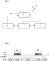
- figure 1 shows a schematic representation of a preferred exemplary embodiment of a circuit diagram of a camera 1 according to the invention, which in particular includes a 3D time-of-flight camera in which a TOF detection method is used.
- the camera 1 comprises an illumination unit 2, which is provided to illuminate during a (in the figure 2 illustrated) lighting phase Bp to emit light pulses to illuminate a surveillance area.
- an image sensor 3 which generates images from the light pulses reflected by an object (not shown).
- the images represent a 3D image, a distance image or a depth map.
- the camera 1 comprises a switching regulator 4, which regulates the current to the lighting unit 2, the switching regulator 4 being operable in a continuous or a discontinuous CCM or DCM mode. That is, the switching regulator 4 is such designed to be switched between the continuous mode CCM and the discontinuous mode DCM and vice versa.
- the camera 1 includes a control unit 5 which is designed to activate and deactivate the continuous mode CCM of the switching controller 4 depending on the lighting phase Bp of the lighting unit 2 .
- the switching controller 4 is able to provide the lighting unit 2 with the full current for the lighting phase Bp.
- the deactivation of the continuous mode CCM or an activation of the discontinuous mode DCM of the switching controller 4 after the lighting phase Bp of the lighting unit 2 prevents a high power loss in the switching controller 4, since the current provided by the discontinuous mode DCM is sufficient for the image sensor 3 can be to evaluate the captured image data.
- the switching regulator 4 can also be provided to regulate current to the image sensor 3 .
- the control unit 5 can more easily regulate the current to the lighting unit 2 and to the image sensor 3 via the switching regulator 4 .
- such a design is not absolutely necessary, since current regulation of the image sensor 3 independently of the switching regulator 4 can also be advantageous.
- an operating sequence of the camera 1 or the switching controller 4 of the camera 1 over time t is as follows:
- the switching regulator 4 is in the discontinuous DCM mode.
- the control unit 5 of the camera 1 switches the switching regulator 4 to the continuous mode CCM, so that at the start of the lighting phase Bp of the lighting unit 2, the full current is available for the lighting unit 2 to ensure sufficient and to ensure stable lighting for capturing the images by the image sensor 3.
- control unit 5 deactivates the continuous CCM mode of the switching regulator 4 and switches the switching regulator 4 to the discontinuous DCM mode. As a result, the full amount of current is not present in the switching regulator 4, so that the power loss can be avoided.
- the current made available by the discontinuous DCM mode can be sufficient for the image sensor 3 to process and evaluate the captured image data, as a result of which a delay in the image capture can be avoided. Eliminating the lag in image acquisition allows improving the efficiency of the camera 1.
- the switching regulator 4 is in the discontinuous DCM mode, so that the power loss of the switching regulator 4 can be significantly reduced, since this intermediate phase is significantly longer than the lighting phase Bp, which is preferably represented by an envelope curve that is in a range from microseconds to milliseconds, such as 500 ⁇ s, and envelops light pulses lying in a range from nanoseconds, such as 3 ns.
- control unit 5 controls the lighting unit 2 again directly or (as shown) indirectly via the image sensor 3 in order to restart the lighting phase Bp
- the control unit 5 activates the continuous CCM mode of the switching controller 4 so that the switching controller 4 switches back to the switches to CCM continuous mode and disables DCM discontinuous mode.
- the lighting unit 2 thus receives the full current intensity for emitting the light pulse or light pulses at the start of the lighting phase Bp.
- the switching controller 4 thus has no dead time, so that the efficiency of the camera 1 is further improved.
Landscapes
- Engineering & Computer Science (AREA)
- Physics & Mathematics (AREA)
- Electromagnetism (AREA)
- Computer Networks & Wireless Communication (AREA)
- General Physics & Mathematics (AREA)
- Radar, Positioning & Navigation (AREA)
- Remote Sensing (AREA)
- Multimedia (AREA)
- Signal Processing (AREA)
- Studio Devices (AREA)
Abstract
Description
- Die Erfindung betrifft eine Kamera, insbesondere eine 3D-Lichtlaufzeitkamera, gemäß dem Anspruch 1.
- Solch eine derartige Kamera arbeitet vorzugsweise nach einem Tastprinzip, bei dem ein Lichtstrahl als Lichtpuls in einen Überwachungsbereich ausgesandt und der von einem Objekt zurückgeworfene Lichtstrahl wieder empfangen wird, um dann das Empfangssignal elektronisch auszuwerten. Hierdurch kann die Kamera einen Abstand messen und gewinnt dadurch eine Tiefeninformation.
- Aus den erfassten dreidimensionalen Bilddaten mit Abstands- oder Entfernungswerten für die einzelnen Pixel werden insbesondere ein 3D-Bild, ein Entfernungsbild oder eine Tiefenkarte erzeugt. Zur Ermittlung der Tiefeninformationen sind verschiedene Verfahren bekannt. Dabei wird oft die Lichtlaufzeit mit einem bekannten Phasen- oder Pulsverfahren gemessen, um den Abstand eines angetasteten Objekts zu bestimmen. Diese Verfahren werden auch TOF (Time-Of-Flight) oder LIDAR (Light Detection And Ranging) genannt.
- Auf diese Weise gewonnene 3D-Bilddaten können in der Automatisierungstechnik dazu genutzt werden, um sich bewegende Aktoren, wie beispielsweise Roboter oder Fahrzeuge, zu steuern.
- Bei Fahrzeugen, die auf öffentlichen Straßen oder in abgeschlossener Umgebung speziell im Bereich der Fabrik- und Logistikautomatik verkehren, soll mit einer 3D-Lichtlaufzeitkamera die gesamte Umgebung und insbesondere ein geplanter Fahrweg möglichst vollständig und dreidimensional erfasst werden. Das betrifft praktisch alle denkbaren Fahrzeuge, seien es solche mit Fahrer wie PKW, LKW, Arbeitsmaschinen und Gabelstapler oder führerlose Fahrzeuge wie AGVs (Automated Guided Vehicle), AGCs (Automated Guided Cart), AMRs (Autonomous Mobile Robot) oder Flurförderfahrzeuge.
- Die 3D-Bilddaten werden beispielsweise genutzt, um einen Fahrer zu unterstützen oder die autonome Navigation zu ermöglichen, unter anderem um Hindernisse zu erkennen, Kollisionen zu vermeiden oder das Be- und Entladen von Transportgütern einschließlich Kartons, Paletten, Containern oder Anhängern zu erleichtern.
- Bei einem Einsatz von 3D-Lichtlaufzeitkameras in einer der oben genannten mobilen Anwendungen ist ein Energieverbrauch der 3D-Lichtlaufzeitkamera entscheidend für eine Laufzeit des mobilen Fahrzeugs. Hierbei trägt die Beleuchtung der 3D-Lichtlaufzeitkamera zur Generierung der 3D Tiefeninformation und somit auch deren Stromversorgung einen großen Teil zum Energieverbrauch bei.
- Bei dem erwähnten TOF Verfahren werden mehrere Messungen zur Phasenschätzung benötigt. Hierzu wird die Beleuchtung kontinuierlich an- und ausgeschaltet, was zu Lastsprüngen in der Energieversorgung der Beleuchtung der 3D-Lichtlaufzeitkamera führt. Durch Auslesen- und Verarbeitungsphasen der Tiefendaten entstehen Beleuchtungspausen, in denen keine oder nur geringe Last in der Energieversorgung der Beleuchtung der 3D-Lichtlaufzeitkamera entsteht.
- Um die Energieversorgung der Beleuchtung der 3D-Lichtlaufzeitkamera zu regeln, werden Schaltregler eingesetzt, die in einem kontinuierlichen Modus (auch Continuous-Current-Mode "CCM" genannt) oder in einem diskontinuierlichen Modus (auch Discontinuous-Current-Mode "DCM" genannt) betrieben werden können.
- Im kontinuierlichen Modus gewährleistet der Schaltregler eine durchgehende Stromversorgung der Beleuchtung der 3D-Lichtlaufzeitkamera, auch wenn die Beleuchtung der 3D-Lichtlaufzeitkamera kein Lichtpuls aussendet. Im diskontinuierlichen Modus ist der Schaltregler ausgelegt, die Beleuchtung der 3D-Lichtlaufzeitkamera nur zum Aussenden des Lichtpulses mit Strom zu versorgen und außerhalb einer Beleuchtungsphase stromlos zu sein. Hierdurch hat der Schaltregler ein schlechtes Ansprechverhalten auf Lastsprünge, wodurch sich Einbußen bei der Messperformance der 3D-Lichtlaufzeitkamera ergeben.
- Es ist eine Aufgabe der Erfindung, eine Kamera mit einer hohen Bildaufnahme bei gleichzeitigem geringen Energieverbrauch zu schaffen.
- Diese Aufgabe wird durch eine Kamera, insbesondere 3D-Lichtlaufzeitkamera, mit den Merkmalen des Anspruchs 1 gelöst. Hierbei umfasst die erfindungsgemäße Kamera, insbesondere 3D- Lichtlaufzeitkamera, eine Beleuchtungseinheit, die Lichtimpulse während einer Beleuchtungsphase aussendet, einen Bildsensor, der aus den von einem Objekt reflektierten Lichtimpulsen Bilder erzeugt, einen Schaltregler, der Strom an die Beleuchtungseinheit regelt, wobei der Schaltregler in einem kontinuierlichen und einem diskontinuierlichen Modus betreibbar ist, und eine Steuereinheit, die ausgebildet ist, den kontinuierlichen Modus des Schaltreglers in Abhängigkeit der Beleuchtungsphase der Beleuchtungseinheit zu aktivieren und zu deaktivieren.
- Hierdurch ergibt sich der technische Vorteil, dass eine Versorgungsspannung, die an dem Schaltregler anliegt, sich nicht verändert und sich somit keine unterschiedlichen Versorgungspegel einstellen, da eine Umschaltung von kontinuierlichem Modus zum diskontinuierlichen Modus und umgekehrt innerhalb des Schaltreglers ausgeführt wird.
- Gemäß einem bevorzugten Ausführungsbeispiel aktiviert die Steuereinheit den kontinuierlichen Modus des Schaltreglers vor einem Einschalten der Beleuchtungseinheit und deaktiviert den kontinuierlichen Modus des Schaltreglers nach einem Ausschalten der Beleuchtungseinheit. Auf diese Weise ist es möglich, zu Beginn der Beleuchtungsphase den vollen Strom für die Beleuchtungseinheit zur Verfügung zu stellen, so dass ein gleichbleibendes Beleuchtungsmuster erzielbar ist.
- Vorteilhafterweise aktiviert die Steuereinheit den diskontinuierlichen Modus zwischen zwei Beleuchtungsphasen der Beleuchtungseinheit, wodurch eine Verlustleistung durch den Schaltregler an sich minimiert ist, wobei keine Regelung der Versorgungsspannung des Schaltreglers notwendig ist.
- Vorzugsweise besteht die Beleuchtungsphase der Beleuchtungseinheit aus einer Hüllkurve, die in einem Bereich von Mikrosekunden bis Millisekunden liegt und in einem Bereich von Nanosekunden liegenden Lichtimpulse einhüllt. Hierdurch ermöglicht die Aktivierung des kontinuierlichen Modus des Schaltreglers eine Umsetzung eines schnellen Beleuchtungsmusters der 3D-Lichtlaufzeitkamera. Ferner ermöglicht die Aktivierung des diskontinuierlichen Modus zwischen den Beleuchtungsphasen ein hohes Einsparungspotential an Verlustleistung des Schaltreglers.
- Gemäß einem bevorzugten Ausführungsbeispiel ist die Steuereinheit in dem Bildsensor integriert vorgesehen, so dass ein kompakter Aufbau der 3D-Lichtlaufzeitkamera möglich ist.
- Vorteilhafterweise ist die Steuereinheit zum Steuern der Beleuchtungsphasen der Beleuchtungseinheit vorgesehen. Dies bedeutet, dass eine einzige Steuereinheit zum Steuern des Schaltreglers, der Beleuchtungseinheit und des Bildsensors vorgesehen werden kann, wodurch die Kompaktheit der 3D-Lichtlaufzeitkamera weiter verbessert ist.
- Die erfindungsgemäße Kamera kann auf ähnliche Weise weitergebildet werden und zeigt dabei ähnliche Vorteile. Derartige vorteilhafte Merkmale sind beispielhaft, aber nicht abschließend in den sich an die unabhängigen Ansprüche anschließenden Unteransprüchen beschrieben.
- Die Erfindung wird nachstehend auch hinsichtlich weiterer Merkmale und Vorteile beispielhaft anhand von Ausführungsformen und unter Bezug auf die beigefügte Zeichnung näher erläutert. Die Abbildungen der Zeichnung zeigen in:
- Fig. 1
- eine schematische Darstellung eines bevorzugten Ausführungsbeispiels eines Schaltbildes einer erfindungsgemäßen Kamera, und
- Fig. 2
- eine schematische Darstellung eines Betriebsablaufs der erfindungsgemä-ßen Kamera über die Zeit.
-
Figur 1 zeigt eine schematische Darstellung eines bevorzugten Ausführungsbeispiels eines Schaltbildes einer erfindungsgemäßen Kamera 1, die insbesondere eine 3D-Lichtlaufzeitkamera umfasst, bei der ein TOF-Erfassungsverfahren angewendet wird. - Die Kamera 1 umfasst eine Beleuchtungseinheit 2, die vorgesehen ist, um während einer (in der
Figur 2 dargestellten) Beleuchtungsphase Bp Lichtimpulse zur Beleuchtung eines Überwachungsbereichs auszusenden. Ferner ist ein Bildsensor 3 vorhanden, der aus den von einem, nicht dargestellten Objekt reflektierten Lichtimpulsen Bilder erzeugt. Die Bilder stellen insbesondere ein 3D-Bild, ein Entfernungsbild oder eine Tiefenkarte dar. - Weiterhin umfasst die Kamera 1 einen Schaltregler 4, der Strom an die Beleuchtungseinheit 2 regelt, wobei der Schaltregler 4 in einem kontinuierlichen oder einem diskontinuierlichen Modus CCM bzw. DCM betreibbar ist. Das heißt, der Schaltregler 4 ist derart ausgebildet, dass er zwischen dem kontinuierlichen Modus CCM und dem diskontinuierlichen Modus DCM und umgekehrt geschaltet werden kann.
- Erfindungsgemäß umfasst die Kamera 1 eine Steuereinheit 5, die ausgebildet ist, den kontinuierlichen Modus CCM des Schaltreglers 4 in Abhängigkeit der Beleuchtungsphase Bp der Beleuchtungseinheit 2 zu aktivieren und zu deaktivieren. Durch die Aktivierung des kontinuierlichen Modus CCM des Schaltreglers 4, insbesondere unmittelbar vor einem Beginn der Beleuchtungsphase Bp der Beleuchtungseinheit 2, ist der Schaltregler 4 in der Lage, der Beleuchtungseinheit 2 den vollen Strom für die Beleuchtungsphase Bp zur Verfügung zu stellen.
- Die Deaktivierung des kontinuierlichen Modus CCM bzw. eine Aktivierung des diskontinuierlichen Modus DCM des Schaltreglers 4 nach der Beleuchtungsphase Bp der Beleuchtungseinheit 2 verhindert eine hohe Verlustleistung in dem Schaltregler 4, da der durch den diskontinuierlichen Modus DCM zur Verfügung gestellte Strom beispielsweise ausreichend für den Bildsensor 3 sein kann, um die erfassten Bilddaten auszuwerten.
- Zusätzlich ermöglicht das Schalten intern des Schaltreglers 4 zwischen diesen beiden Modi CCM und DCM, dass eine am Schaltregler 4 anliegende Versorgungsspannung Vin nicht beeinflusst wird.
- Wie in der
Figur 1 dargestellt, kann der Schaltregler 4 auch dafür vorgesehen sein, Strom an den Bildsensor 3 zu regeln. Hierdurch kann die Steuereinheit 5 den Strom über den Schaltregler 4 einfacher an die Beleuchtungseinheit 2 und an den Bildsensor 3 regeln. Jedoch ist solch eine Auslegung nicht zwingend erforderlich, da eine Stromregelung des Bildsensors 3 unabhängig vom Schaltregler 4 auch vorteilhaft sein kann. - Wie in der
Figur 2 dargestellt, läuft ein Betriebsablauf der Kamera 1 bzw. des Schaltreglers 4 der Kamera 1 über die Zeit t wie folgt ab:
Mit Anliegen der Versorgungsspannung Vin befindet sich der Schaltregler 4 in dem diskontinuierlichen Modus DCM. Vor einem Start der Beleuchtungsphase Bp der Beleuchtungseinheit 2 schaltet die Steuereinheit 5 der Kamera 1 den Schaltregler 4 in den kontinuierlichen Modus CCM, so dass mit Beginn der Beleuchtungsphase Bp der Beleuchtungseinheit 2 der volle Strom für die Beleuchtungseinheit 2 zur Verfügung steht, um eine ausreichende und stabile Beleuchtung für eine Erfassung der Bilder durch den Bildsensor 3 zu gewährleisten. - Nach Ende der Beleuchtungsphase Bp der Beleuchtungseinheit 2 deaktiviert die Steuereinheit 5 den kontinuierlichen Modus CCM des Schaltreglers 4 und schaltet den Schaltregler 4 in den diskontinuierlichen Modus DCM. Hierdurch steht kein voller Strombetrag im Schaltregler 4 an, so dass die Verlustleistung vermieden werden kann.
- Ferner kann der durch den diskontinuierlichen Modus DCM zur Verfügung gestellte Strom ausreichend für den Bildsensor 3 sein, die erfassten Bilddaten zu verarbeiten und auszuwerten, wodurch eine Verzögerung der Bilderfassung vermieden werden kann. Die Vermeidung der Verzögerung der Bilderfassung ermöglicht eine Verbesserung der Effizienz der Kamera 1.
- Zwischen zwei Beleuchtungsphase Bp der Beleuchtungseinheit 2 befindet sich der Schaltregler 4 in dem diskontinuierlichen Modus DCM, so dass die Verlustleistung des Schaltreglers 4 signifikant reduziert werden kann, da diese Zwischenphase wesentlich länger ist als die Beleuchtungsphase Bp, die vorzugsweise durch eine Hüllkurve wiedergegeben ist, die in einem Bereich von Mikrosekunden bis Millisekunden, wie beispielsweise von 500µs, liegt und in einem Bereich von Nanosekunden, wie beispielsweise von 3 ns, liegende Lichtimpulse einhüllt.
- Sobald die Steuereinheit 5 die Beleuchtungseinheit 2 direkt oder (wie dargestellt) indirekt über den Bildsensor 3 erneut ansteuert, um die Beleuchtungsphase Bp wieder zu starten, aktiviert die Steuereinheit 5 den kontinuierlichen Modus CCM des Schaltreglers 4, so dass sich der Schaltregler 4 erneut in den kontinuierlichen Modus CCM schaltet und den diskontinuierlichen Modus DCM deaktiviert.
- Die Beleuchtungseinheit 2 erhält damit die volle Stromstärke zum Aussenden des Lichtpulses bzw. der Lichtpulse mit dem Start der Beleuchtungsphase Bp. Der Schaltregler 4 weist damit keine Totzeit auf, so dass die Effizienz der Kamera 1 weiter verbessert ist.
-
- 1
- Kamera
- 2
- Beleuchtungseinheit
- 3
- Bildsensor
- 4
- Schaltregler
- 5
- Steuereinheit
- Bp
- Beleuchtungsphase
- DCM
- diskontinuierlicher Modus
- CCM
- kontinuierlicher Modus
- t
- Zeit
- Vin
- Versorgungsspannung
Claims (6)
- Kamera (1), insbesondere 3D- Lichtlaufzeitkamera, miteiner Beleuchtungseinheit (2), die Lichtimpulse während einer Beleuchtungsphase (Bp) aussendet,einem Bildsensor (3), der aus den von einem Objekt reflektierten Lichtimpulsen Bilder erzeugt,einem Schaltregler (4), der Strom an die Beleuchtungseinheit (2) regelt, wobei der Schaltregler (4) in einem kontinuierlichen und einem diskontinuierlichen Modus (CCM; DCM) betreibbar ist, undeiner Steuereinheit (5), die ausgebildet ist, den kontinuierlichen Modus (CCM) des Schaltreglers (4) in Abhängigkeit der Beleuchtungsphase (Bp) der Beleuchtungseinheit (2) zu aktivieren und zu deaktivieren.
- Kamera (1) nach Anspruch 1, wobei die Steuereinheit (5) den kontinuierlichen Modus (CCM) des Schaltreglers (4) vor einem Einschalten der Beleuchtungseinheit (2) aktiviert und nach einem Ausschalten der Beleuchtungseinheit (2) deaktiviert.
- Kamera (1) nach Anspruch 1 oder 2, wobei die Steuereinheit (5) den diskontinuierlichen Modus (DCM) zwischen zwei Beleuchtungsphasen (Bp) der Beleuchtungseinheit (2) aktiviert.
- Kamera (1) nach einem der vorhergehenden Ansprüche, wobei die Beleuchtungsphase (Bp) der Beleuchtungseinheit (2) durch eine Hüllkurve wiedergegeben ist, die in einem Bereich von Mikrosekunden bis Millisekunden liegt und in einem Bereich von Nanosekunden liegende Lichtimpulse einhüllt.
- Kamera (1) nach einem der vorhergehenden Ansprüche, wobei die Steuereinheit (5) in dem Bildsensor (3) integriert vorgesehen ist.
- Kamera (1) nach einem der vorhergehenden Ansprüche, wobei die Steuereinheit (5) zum Steuern der Beleuchtungsphasen (Bp) der Beleuchtungseinheit (2) vorgesehen ist.
Applications Claiming Priority (1)
| Application Number | Priority Date | Filing Date | Title |
|---|---|---|---|
| DE102021116651.9A DE102021116651A1 (de) | 2021-06-28 | 2021-06-28 | Kamera |
Publications (2)
| Publication Number | Publication Date |
|---|---|
| EP4113161A1 true EP4113161A1 (de) | 2023-01-04 |
| EP4113161B1 EP4113161B1 (de) | 2025-07-30 |
Family
ID=82016509
Family Applications (1)
| Application Number | Title | Priority Date | Filing Date |
|---|---|---|---|
| EP22177874.9A Active EP4113161B1 (de) | 2021-06-28 | 2022-06-08 | Kamera |
Country Status (3)
| Country | Link |
|---|---|
| US (1) | US12013461B2 (de) |
| EP (1) | EP4113161B1 (de) |
| DE (1) | DE102021116651A1 (de) |
Citations (2)
| Publication number | Priority date | Publication date | Assignee | Title |
|---|---|---|---|---|
| US20150312983A1 (en) * | 2014-04-25 | 2015-10-29 | Cree, Inc. | High efficiency driver circuit with fast response |
| DE102014105482B4 (de) * | 2013-04-19 | 2020-01-16 | Infineon Technologies Ag | Treiberschaltung für ein lichtemittierendes Element und Laufzeitdetektor |
Family Cites Families (5)
| Publication number | Priority date | Publication date | Assignee | Title |
|---|---|---|---|---|
| US7128266B2 (en) * | 2003-11-13 | 2006-10-31 | Metrologic Instruments. Inc. | Hand-supportable digital imaging-based bar code symbol reader supporting narrow-area and wide-area modes of illumination and image capture |
| US7490774B2 (en) * | 2003-11-13 | 2009-02-17 | Metrologic Instruments, Inc. | Hand-supportable imaging based bar code symbol reader employing automatic light exposure measurement and illumination control subsystem integrated therein |
| DE102011112455A1 (de) | 2011-09-03 | 2013-03-07 | Vision Components Gesellschaft für Bildverarbeitungsysteme mbH | Verfahren und elektronische Schaltung zur Stromversorgung für eine gepulste Beleuchtungsquelle |
| TWI587698B (zh) * | 2016-03-31 | 2017-06-11 | 晶睿通訊股份有限公司 | 攝影裝置及曝光亮度調整方法 |
| US11598849B2 (en) * | 2017-12-03 | 2023-03-07 | Munro Design & Technologies, Llc | Signal generating systems for three-dimensional imaging systems and methods thereof |
-
2021
- 2021-06-28 DE DE102021116651.9A patent/DE102021116651A1/de active Pending
-
2022
- 2022-06-08 EP EP22177874.9A patent/EP4113161B1/de active Active
- 2022-06-27 US US17/850,330 patent/US12013461B2/en active Active
Patent Citations (2)
| Publication number | Priority date | Publication date | Assignee | Title |
|---|---|---|---|---|
| DE102014105482B4 (de) * | 2013-04-19 | 2020-01-16 | Infineon Technologies Ag | Treiberschaltung für ein lichtemittierendes Element und Laufzeitdetektor |
| US20150312983A1 (en) * | 2014-04-25 | 2015-10-29 | Cree, Inc. | High efficiency driver circuit with fast response |
Also Published As
| Publication number | Publication date |
|---|---|
| DE102021116651A1 (de) | 2022-12-29 |
| US12013461B2 (en) | 2024-06-18 |
| EP4113161B1 (de) | 2025-07-30 |
| US20220413155A1 (en) | 2022-12-29 |
Similar Documents
| Publication | Publication Date | Title |
|---|---|---|
| EP3323770B1 (de) | Verfahren zur bereitstellung der positionen von lagerplätzen in einem lager und flurförderzeug | |
| EP3510584B1 (de) | System und verfahren zum operieren von nutzfahrzeugen | |
| DE112015001150B4 (de) | Verfahren, Vorrichtung und System zur Unterstützung von Platooning | |
| DE102019108477A1 (de) | Automatische navigation unter verwendung von deep reinforcement learning | |
| DE102018133576A1 (de) | Trajektorienplaner mit dynamischem kostenlernen für autonomes fahren | |
| DE102005015836B4 (de) | Fahrzeugradarsystem | |
| DE102014118204B4 (de) | Distanzermittlungssystem für ein fahrzeug unter verwendung von holografischen techniken | |
| EP4187345A1 (de) | Verfahren zum planen einer route für ein fahrerloses transportfahrzeug | |
| DE102017008569A1 (de) | Verfahren zum Betreiben eines Fahrerassistenzsystems für ein Kraftfahrzeug unter Verwendung einer vektorbasierten und einer gitterbassierten Umgebungskarte sowie Fahrerassistenzsystem | |
| DE102019208828A1 (de) | Adas-verbundene aktive motorhaubenvorrichtung und verfahren zum steuern derselben | |
| DE102017120845A1 (de) | Verfahren und Systeme zur adaptiven On-Demand-Infrarot-Fahrspurerkennung | |
| DE112017003982T5 (de) | Systeme und Verfahren zum Steuern von Fahrzeugmanövern | |
| EP4102330B1 (de) | Verfahren zum bewegen eines fahrzeugs an eine komponente eines hierzu beabstandeten objekts (koordinatentransformation) | |
| DE102015106305B4 (de) | Beleuchtungsvorrichtung und Verfahren zur Versorgung | |
| EP3805891A1 (de) | Fahrerloses transportfahrzeug für die innerbetriebliche warenlogistik | |
| DE102006035929A1 (de) | Verfahren zum sensorgestützten Unterfahren eines Objekts bzw. zum Einfahren in ein Objekt mit einem Nutzfahrzeug | |
| DE102015113445A1 (de) | Verfahren zur Geschwindigkeitssteuerung eines Kommissionierflurförderzeugs | |
| EP4113161B1 (de) | Kamera | |
| DE202021103446U1 (de) | Kamera | |
| DE102020104329A1 (de) | Kalibrierung eines Umfeldsensorsystems eines Kraftfahrzeugs | |
| DE102004047214B4 (de) | Verfahren zur Navigation für Transportfahrzeuge | |
| EP4433883A1 (de) | Verfahren zur unterstützenden oder automatisierten fahrzeugführung | |
| DE102022208059B3 (de) | Verfahren zum Ermitteln einer eine Parklücke beschreibenden Umfeldinformation mithilfe eines faltenden neuronalen Netzes | |
| EP4296815B1 (de) | Verfahren zum bestimmen einer trajektorie für ein mobiles gerät | |
| DE102020211916A1 (de) | Fahrzeug und steuerverfahren desselben |
Legal Events
| Date | Code | Title | Description |
|---|---|---|---|
| PUAI | Public reference made under article 153(3) epc to a published international application that has entered the european phase |
Free format text: ORIGINAL CODE: 0009012 |
|
| STAA | Information on the status of an ep patent application or granted ep patent |
Free format text: STATUS: THE APPLICATION HAS BEEN PUBLISHED |
|
| AK | Designated contracting states |
Kind code of ref document: A1 Designated state(s): AL AT BE BG CH CY CZ DE DK EE ES FI FR GB GR HR HU IE IS IT LI LT LU LV MC MK MT NL NO PL PT RO RS SE SI SK SM TR |
|
| STAA | Information on the status of an ep patent application or granted ep patent |
Free format text: STATUS: REQUEST FOR EXAMINATION WAS MADE |
|
| 17P | Request for examination filed |
Effective date: 20230314 |
|
| RBV | Designated contracting states (corrected) |
Designated state(s): AL AT BE BG CH CY CZ DE DK EE ES FI FR GB GR HR HU IE IS IT LI LT LU LV MC MK MT NL NO PL PT RO RS SE SI SK SM TR |
|
| GRAP | Despatch of communication of intention to grant a patent |
Free format text: ORIGINAL CODE: EPIDOSNIGR1 |
|
| STAA | Information on the status of an ep patent application or granted ep patent |
Free format text: STATUS: GRANT OF PATENT IS INTENDED |
|
| RIC1 | Information provided on ipc code assigned before grant |
Ipc: G01S 17/894 20200101ALI20250127BHEP Ipc: G01S 7/483 20060101AFI20250127BHEP |
|
| INTG | Intention to grant announced |
Effective date: 20250206 |
|
| GRAS | Grant fee paid |
Free format text: ORIGINAL CODE: EPIDOSNIGR3 |
|
| GRAA | (expected) grant |
Free format text: ORIGINAL CODE: 0009210 |
|
| STAA | Information on the status of an ep patent application or granted ep patent |
Free format text: STATUS: THE PATENT HAS BEEN GRANTED |
|
| AK | Designated contracting states |
Kind code of ref document: B1 Designated state(s): AL AT BE BG CH CY CZ DE DK EE ES FI FR GB GR HR HU IE IS IT LI LT LU LV MC MK MT NL NO PL PT RO RS SE SI SK SM TR |
|
| REG | Reference to a national code |
Ref country code: GB Ref legal event code: FG4D Free format text: NOT ENGLISH |
|
| REG | Reference to a national code |
Ref country code: CH Ref legal event code: EP |
|
| REG | Reference to a national code |
Ref country code: DE Ref legal event code: R096 Ref document number: 502022004804 Country of ref document: DE |
|
| REG | Reference to a national code |
Ref country code: IE Ref legal event code: FG4D Free format text: LANGUAGE OF EP DOCUMENT: GERMAN |
|
| REG | Reference to a national code |
Ref country code: NL Ref legal event code: MP Effective date: 20250730 |
|
| PG25 | Lapsed in a contracting state [announced via postgrant information from national office to epo] |
Ref country code: PT Free format text: LAPSE BECAUSE OF FAILURE TO SUBMIT A TRANSLATION OF THE DESCRIPTION OR TO PAY THE FEE WITHIN THE PRESCRIBED TIME-LIMIT Effective date: 20251202 |
|
| PG25 | Lapsed in a contracting state [announced via postgrant information from national office to epo] |
Ref country code: IS Free format text: LAPSE BECAUSE OF FAILURE TO SUBMIT A TRANSLATION OF THE DESCRIPTION OR TO PAY THE FEE WITHIN THE PRESCRIBED TIME-LIMIT Effective date: 20251130 |
|
| PG25 | Lapsed in a contracting state [announced via postgrant information from national office to epo] |
Ref country code: NO Free format text: LAPSE BECAUSE OF FAILURE TO SUBMIT A TRANSLATION OF THE DESCRIPTION OR TO PAY THE FEE WITHIN THE PRESCRIBED TIME-LIMIT Effective date: 20251030 |
|
| REG | Reference to a national code |
Ref country code: LT Ref legal event code: MG9D |
|
| PG25 | Lapsed in a contracting state [announced via postgrant information from national office to epo] |
Ref country code: FI Free format text: LAPSE BECAUSE OF FAILURE TO SUBMIT A TRANSLATION OF THE DESCRIPTION OR TO PAY THE FEE WITHIN THE PRESCRIBED TIME-LIMIT Effective date: 20250730 |
|
| PG25 | Lapsed in a contracting state [announced via postgrant information from national office to epo] |
Ref country code: NL Free format text: LAPSE BECAUSE OF FAILURE TO SUBMIT A TRANSLATION OF THE DESCRIPTION OR TO PAY THE FEE WITHIN THE PRESCRIBED TIME-LIMIT Effective date: 20250730 Ref country code: HR Free format text: LAPSE BECAUSE OF FAILURE TO SUBMIT A TRANSLATION OF THE DESCRIPTION OR TO PAY THE FEE WITHIN THE PRESCRIBED TIME-LIMIT Effective date: 20250730 |
|
| PG25 | Lapsed in a contracting state [announced via postgrant information from national office to epo] |
Ref country code: GR Free format text: LAPSE BECAUSE OF FAILURE TO SUBMIT A TRANSLATION OF THE DESCRIPTION OR TO PAY THE FEE WITHIN THE PRESCRIBED TIME-LIMIT Effective date: 20251031 |
|
| PG25 | Lapsed in a contracting state [announced via postgrant information from national office to epo] |
Ref country code: SE Free format text: LAPSE BECAUSE OF FAILURE TO SUBMIT A TRANSLATION OF THE DESCRIPTION OR TO PAY THE FEE WITHIN THE PRESCRIBED TIME-LIMIT Effective date: 20250730 |
|
| PG25 | Lapsed in a contracting state [announced via postgrant information from national office to epo] |
Ref country code: LV Free format text: LAPSE BECAUSE OF FAILURE TO SUBMIT A TRANSLATION OF THE DESCRIPTION OR TO PAY THE FEE WITHIN THE PRESCRIBED TIME-LIMIT Effective date: 20250730 |
|
| PG25 | Lapsed in a contracting state [announced via postgrant information from national office to epo] |
Ref country code: BG Free format text: LAPSE BECAUSE OF FAILURE TO SUBMIT A TRANSLATION OF THE DESCRIPTION OR TO PAY THE FEE WITHIN THE PRESCRIBED TIME-LIMIT Effective date: 20250730 Ref country code: PL Free format text: LAPSE BECAUSE OF FAILURE TO SUBMIT A TRANSLATION OF THE DESCRIPTION OR TO PAY THE FEE WITHIN THE PRESCRIBED TIME-LIMIT Effective date: 20250730 |
|
| PG25 | Lapsed in a contracting state [announced via postgrant information from national office to epo] |
Ref country code: RS Free format text: LAPSE BECAUSE OF FAILURE TO SUBMIT A TRANSLATION OF THE DESCRIPTION OR TO PAY THE FEE WITHIN THE PRESCRIBED TIME-LIMIT Effective date: 20251030 |
|
| PG25 | Lapsed in a contracting state [announced via postgrant information from national office to epo] |
Ref country code: ES Free format text: LAPSE BECAUSE OF FAILURE TO SUBMIT A TRANSLATION OF THE DESCRIPTION OR TO PAY THE FEE WITHIN THE PRESCRIBED TIME-LIMIT Effective date: 20250730 |
|
| PG25 | Lapsed in a contracting state [announced via postgrant information from national office to epo] |
Ref country code: SM Free format text: LAPSE BECAUSE OF FAILURE TO SUBMIT A TRANSLATION OF THE DESCRIPTION OR TO PAY THE FEE WITHIN THE PRESCRIBED TIME-LIMIT Effective date: 20250730 |
|
| PG25 | Lapsed in a contracting state [announced via postgrant information from national office to epo] |
Ref country code: DK Free format text: LAPSE BECAUSE OF FAILURE TO SUBMIT A TRANSLATION OF THE DESCRIPTION OR TO PAY THE FEE WITHIN THE PRESCRIBED TIME-LIMIT Effective date: 20250730 |
|
| PG25 | Lapsed in a contracting state [announced via postgrant information from national office to epo] |
Ref country code: IT Free format text: LAPSE BECAUSE OF FAILURE TO SUBMIT A TRANSLATION OF THE DESCRIPTION OR TO PAY THE FEE WITHIN THE PRESCRIBED TIME-LIMIT Effective date: 20250730 |
|
| PG25 | Lapsed in a contracting state [announced via postgrant information from national office to epo] |
Ref country code: CZ Free format text: LAPSE BECAUSE OF FAILURE TO SUBMIT A TRANSLATION OF THE DESCRIPTION OR TO PAY THE FEE WITHIN THE PRESCRIBED TIME-LIMIT Effective date: 20250730 |
|
| PG25 | Lapsed in a contracting state [announced via postgrant information from national office to epo] |
Ref country code: EE Free format text: LAPSE BECAUSE OF FAILURE TO SUBMIT A TRANSLATION OF THE DESCRIPTION OR TO PAY THE FEE WITHIN THE PRESCRIBED TIME-LIMIT Effective date: 20250730 Ref country code: SK Free format text: LAPSE BECAUSE OF FAILURE TO SUBMIT A TRANSLATION OF THE DESCRIPTION OR TO PAY THE FEE WITHIN THE PRESCRIBED TIME-LIMIT Effective date: 20250730 |