EP4113067A1 - Use of channel information to generate redundant angle measurements on safety critical applications - Google Patents
Use of channel information to generate redundant angle measurements on safety critical applications Download PDFInfo
- Publication number
- EP4113067A1 EP4113067A1 EP22168908.6A EP22168908A EP4113067A1 EP 4113067 A1 EP4113067 A1 EP 4113067A1 EP 22168908 A EP22168908 A EP 22168908A EP 4113067 A1 EP4113067 A1 EP 4113067A1
- Authority
- EP
- European Patent Office
- Prior art keywords
- magnetic field
- angle
- field sensors
- magnet
- sensors
- Prior art date
- Legal status (The legal status is an assumption and is not a legal conclusion. Google has not performed a legal analysis and makes no representation as to the accuracy of the status listed.)
- Granted
Links
Images



Classifications
-
- G—PHYSICS
- G01—MEASURING; TESTING
- G01B—MEASURING LENGTH, THICKNESS OR SIMILAR LINEAR DIMENSIONS; MEASURING ANGLES; MEASURING AREAS; MEASURING IRREGULARITIES OF SURFACES OR CONTOURS
- G01B7/00—Measuring arrangements characterised by the use of electric or magnetic techniques
- G01B7/30—Measuring arrangements characterised by the use of electric or magnetic techniques for measuring angles or tapers; for testing the alignment of axes
-
- G—PHYSICS
- G01—MEASURING; TESTING
- G01D—MEASURING NOT SPECIALLY ADAPTED FOR A SPECIFIC VARIABLE; ARRANGEMENTS FOR MEASURING TWO OR MORE VARIABLES NOT COVERED IN A SINGLE OTHER SUBCLASS; TARIFF METERING APPARATUS; MEASURING OR TESTING NOT OTHERWISE PROVIDED FOR
- G01D18/00—Testing or calibrating apparatus or arrangements provided for in groups G01D1/00 - G01D15/00
-
- G—PHYSICS
- G01—MEASURING; TESTING
- G01D—MEASURING NOT SPECIALLY ADAPTED FOR A SPECIFIC VARIABLE; ARRANGEMENTS FOR MEASURING TWO OR MORE VARIABLES NOT COVERED IN A SINGLE OTHER SUBCLASS; TARIFF METERING APPARATUS; MEASURING OR TESTING NOT OTHERWISE PROVIDED FOR
- G01D3/00—Indicating or recording apparatus with provision for the special purposes referred to in the subgroups
- G01D3/08—Indicating or recording apparatus with provision for the special purposes referred to in the subgroups with provision for safeguarding the apparatus, e.g. against abnormal operation, against breakdown
-
- G—PHYSICS
- G01—MEASURING; TESTING
- G01D—MEASURING NOT SPECIALLY ADAPTED FOR A SPECIFIC VARIABLE; ARRANGEMENTS FOR MEASURING TWO OR MORE VARIABLES NOT COVERED IN A SINGLE OTHER SUBCLASS; TARIFF METERING APPARATUS; MEASURING OR TESTING NOT OTHERWISE PROVIDED FOR
- G01D5/00—Mechanical means for transferring the output of a sensing member; Means for converting the output of a sensing member to another variable where the form or nature of the sensing member does not constrain the means for converting; Transducers not specially adapted for a specific variable
- G01D5/12—Mechanical means for transferring the output of a sensing member; Means for converting the output of a sensing member to another variable where the form or nature of the sensing member does not constrain the means for converting; Transducers not specially adapted for a specific variable using electric or magnetic means
- G01D5/14—Mechanical means for transferring the output of a sensing member; Means for converting the output of a sensing member to another variable where the form or nature of the sensing member does not constrain the means for converting; Transducers not specially adapted for a specific variable using electric or magnetic means influencing the magnitude of a current or voltage
- G01D5/142—Mechanical means for transferring the output of a sensing member; Means for converting the output of a sensing member to another variable where the form or nature of the sensing member does not constrain the means for converting; Transducers not specially adapted for a specific variable using electric or magnetic means influencing the magnitude of a current or voltage using Hall-effect devices
- G01D5/145—Mechanical means for transferring the output of a sensing member; Means for converting the output of a sensing member to another variable where the form or nature of the sensing member does not constrain the means for converting; Transducers not specially adapted for a specific variable using electric or magnetic means influencing the magnitude of a current or voltage using Hall-effect devices influenced by the relative movement between the Hall device and magnetic fields
Definitions
- the disclosure pertains generally to arrangements for measuring magnetic variables, and more particularly to measuring direction of magnetic fields using Hall-effect devices.
- ASIL Safety Integrity Level
- ISO International Electrotechnical Commission
- a magnetic angle and rotation sensing system 100 As shown in Figure 1 .
- a rotating component such as a steering column has affixed to it a cylindrical magnet 110 that is diametrically magnetized; that is, the North and South poles of the magnet 110 lie along a cross-sectional diameter as indicated, rather than along its central axis 120.
- the magnet 110 is made of rare earth elements (e.g. neodymium) that produce a strong local field for sensing.
- the magnet 110 When the component rotates, the magnet 110 likewise rotates about its central axis 120, thereby changing the direction of the axis of magnetization (i.e. the direction from the South pole to the North pole). This results in a change in the orientation of the external, opposite magnetic field (i.e. from the North pole to the South pole), which may be sensed using a sensor 130 that is located in a plane parallel to a face of the cylindrical magnet 110.
- the sensor 130 contains compact, robust magnetic field sensors such as Hall plate sensors.
- Disclosed embodiments provide an angle sensor system that is immune to stray magnetic fields; that is, it is sensitive to differential fields but not to common-mode fields. This is accomplished through the observation that magnetic field strength on a circle, centered on the axis of rotation but in a plane perpendicular to it, have a component parallel to the axis that varies sinusoidally as a function of the angle around the circle. By placing magnetic field sensors equiangularly around such a circle, and summing their field strengths with appropriate weights, the angle of magnet rotation may be computed in a manner that is immune to the presence of stray fields. Moreover, fewer than all channels of sense data may be combined to form redundant estimates of the angle of rotation, to permit continued operation when one of the sensors has failed.
- a first embodiment is a sensor system for sensing rotation of a magnet about a given axis.
- the sensor system includes at least three magnetic field sensors, each sensor for sensing a strength of the magnetic field parallel to the given axis.
- the plurality of magnetic field sensors are arranged, in a plane perpendicular to the given axis, equiangularly around a circle whose center lies on the given axis.
- the sensor also includes electronic circuitry, coupled to the plurality of magnetic field sensors, for combining the respective sensed strengths into an output signal that represents an angle ⁇ between a magnetization axis of the magnet and a fixed direction.
- At least one of the magnetic field sensors comprises a Hall-effect plate sensor.
- the magnet comprises a diametric cylinder magnet and the plurality of magnetic field sensors comprises at least four magnetic field sensors.
- the magnet does not comprise a diametric cylinder magnet and the plurality of magnetic field sensors comprises at least five magnetic field sensors.
- the electronic circuitry is configured for combining the sensed strengths in a manner that is insensitive to common-mode components of the magnetic field present at each of the magnetic field sensors.
- the electronic circuitry further includes a plurality of subsidiary angle derivation circuits, each subsidiary angle derivation circuit for combining the sensed strengths, from a different subset of fewer than the total number of the plurality of magnetic field sensors, to form a respective redundant value for the angle ⁇ .
- the electronic circuitry further includes a main angle comparator circuit for comparing the redundant values for the angle ⁇ produced by each of the plurality of subsidiary angle derivation circuits to determine whether a magnetic field sensor is faulty.
- the electronic circuitry further includes a main angle comparator circuit for determining a most likely value for the angle ⁇ by comparing the redundant values for the angle ⁇ according to a majority vote.
- Some embodiments include both a main angle comparator circuit and a redundant angle comparator circuit, both circuits for comparing the redundant values for the angle ⁇
- Another embodiment is a method of sensing rotation of a magnet about a given axis.
- the method includes sensing a strength of the magnetic field parallel to the given axis, by each of a plurality of at least three magnetic field sensors.
- the magnetic field sensors are arranged, in a plane perpendicular to the given axis, equiangularly around a circle whose center lies on the given axis.
- the method also includes combining the respective sensed strengths, by electronic circuitry coupled to the plurality of magnetic field sensors, into an output signal that represents an angle ⁇ between a magnetization axis of the magnet and a fixed direction.
- sensing the strength of the magnetic field by a magnetic field sensor comprises sensing using the Hall effect.
- the magnet comprises a diametric cylinder magnet and the plurality of magnetic field sensors comprises at least four magnetic field sensors.
- the magnet does not comprise a diametric cylinder magnet and the plurality of magnetic field sensors comprises at least five magnetic field sensors.
- combining the sensed strengths into the output signal comprises combining the sensed strength in a manner that is insensitive to common-mode components of the magnetic field present at each of the magnetic field sensors.
- combining the sensed strengths comprises combining sensed strengths, from each of a plurality of different subsets of fewer than the total number of the plurality of magnetic field sensors, to form a respective redundant value for the angle ⁇ .
- Some embodiments of the method further include comparing the redundant values for the angle ⁇ to determine whether one of the magnetic field sensors is faulty.
- Some embodiments of the method include determining a most likely value for the angle ⁇ by comparing the redundant values for the angle ⁇ according to a majority vote.
- Some embodiments of the method further include comparing the redundant values for the angle ⁇ by both a main angle comparator circuit and a redundant angle comparator circuit.
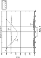
- Figure 2 a plot of simulated magnetic field strength in each of three directions at points around a circle in the sensing plane of Figure 1 .
- the magnet being sensed may be the diametrically-magnetized magnet 110, and is oriented with its North pole in the +X direction and its South pole in the -X direction.
- the system is configured so that the magnet may rotate about an axis of rotation, which may be central axis 120.
- the magnet is held fixed as described above, while its magnetic field is sensed.
- the sensing plane contains the sensor, which may be sensor 130, and is a distance above the magnet and oriented in a plane parallel to the top surface of the magnet.
- the magnetic field Bx in the X direction is shown by curve 210.
- This curve 210 is relatively flat and shows a field of approximately -950 Gauss (i.e., a field uniformly in the -X direction with a strength of 950 Gauss).
- This reflects the fact that the sensed field will have a North-to-South orientation that opposite of the South-to-North magnetization internal to the magnet itself.
- the sensed field strength is approximately independent of the angular position of the sensor around the circle in the sensing plane. Rather, this sensed field is a function of the distance of the sensor plane above the magnet, and will become weaker as this distance increases.
- the magnetic field By in the Y direction is shown by curve 220.
- This curve 220 is also relatively flat and shows a field of approximately 0 Gauss. This reflects the fact that, when the magnetization direction of the magnet is South-to-North, the sensed external magnetic field will be North-to-South, and thus have no component in the +Y (i.e. East-to-West) or -Y (i.e. West-to-East) directions for small distances from the magnet's axis of rotation.
- the magnetic field Bz in the Z direction is shown by curve 230.
- This curve 230 oscillates sinusoidally based on the angular position of the sensor, having its maximum value for the (simulated) sensor farthest in the +X (i.e. North) direction and having its minimum value for the sensor farthest in the -X (i.e. South) direction.
- the maximum and minimum values of the sensed field have approximately the same magnitudes, about 250 Gauss, but in opposite directions. This reflects the fact that the external magnetic field lines curve in the Z direction from the North pole to the South pole, curving in the +Z direction (i.e. away from the magnet) on the North side of the sensing plane and curving in the -Z direction (i.e. toward the magnet) on the South side of the sensing plane.
- the regular, sinusoidal behavior of the Z-component of the magnetic field in the sensing plane may be used to detect rotation of the magnet about a stationary sensor system having multiple magnetic field sensors contained within. It is further appreciated that three or more magnetic field sensors, arranged in a circle centered in the plane about its intersection with the axis of rotation of the magnet, provide multiple channels of information that may be used not only to detect fault in the sensor integrated circuit as known in the prior art, but that may be combined to add redundancy to the detection so that the angle of rotation of the magnet may be accurately sensed even if one of the magnetic field sensors fails.
- Figure 3 a cartoon of a top-down view of a magnet and four magnetic field sensors arranged equiangularly around a circle in the sensing plane in accordance with an embodiment.
- Figure 3 has the indicated coordinate system, with the +X axis toward the right and the +Y axis toward the top.
- the +Z axis (not shown) is, by the right-hand rule, out of the Figure toward the reader.
- the +X axis may be chosen as a neutral position of the magnet 300, i.e. one in which its axis of magnetization 310 is in a position that corresponds to a passive, rather than active, state of the control system.
- the axis of magnetization 310 in Figure 3 is offset from its neutral position along the X axis due to rotation of the magnet 300 about its axis of rotation (i.e. the Z axis) by an angle ⁇ .
- the angle ⁇ is computed using the outputs of four magnetic field sensors 320, 322, 324, 326. Any or all of the magnetic field sensors may be, illustratively, Hall-effect plate sensors.
- Each of the magnetic field sensors 320-326 senses a strength of the magnetic field in the Z direction, i.e. in a direction parallel to the axis of rotation of the magnet 300.
- the magnetic field sensors 320-326 themselves are contained in a plane perpendicular to the axis of rotation, i.e.
- the magnetic field sensors 320-326 are further arranged equiangularly around the circle 330, whose center lies on the intersection between the sensing plane and the +Z axis. That is, the center of the circle 330 lies on the axis of rotation of the magnet 300.
- n the total number of magnetic field sensors, where n is at least three.
- the radius of the circle of sensors may be selected, according to the dimensions of the magnet and the design parameters of the sensor system, so that a Z component of the magnetic field present at each sensor is strong enough to permit accurate measurement.
- the magnetic field sensed by each sensor is weighted by its planar coordinates, the results are summed to produce x and y coordinates of a point 340 in the sensor plane above the axis of magnetization 310, then the inverse tangent of the ratio y / x is computed to identify the angle ⁇ .
- n 4 magnetic field sensors 320 (sensing H 1 ), 322 (sensing H 2 ), 324 (sensing H 3 ), and 326 (sensing H 4 )
- ⁇ tan ⁇ 1 H 2 ⁇ H 4 H 1 ⁇ H 3 .
- H the magnitude of a uniform magnetic field in the Z direction that is present at each of the sensors of Figure 3 .
- H will be positive if the field is in the +Z direction, and negative if the field is in the -Z direction.
- the combined magnetic field from both the magnet and the common-mode field that is sensed by sensor # i has the value H i + H.
- intrinsic angular error- that is, the error in an ideal system without mechanical tolerances and without any measurement error-is zero only if the target magnet is cylindrical, i.e. a magnet with circular symmetry that matches the symmetry of the magnetic field sensor arrangement.
- the magnet is a diametrically magnetized cylinder magnet
- four magnetic field sensors is sufficient, although more may be employed.
- the target magnet is not cylindrical, then intrinsic angular error will not be zero, but may be reduced by increasing the number n of magnetic field sensors.
- the target magnet is not a diametric cylinder magnet, then five or more magnetic field sensors should be used.
- embodiments may be used with a target magnet of any arbitrary shape, and the disclosure herein should not be construed as limiting embodiments to use with only diametrically magnetized cylinders.
- the circle of sensors may be misaligned with the axis of rotation of the target magnet.
- the sinusoidal variation of sensed B Z indicated in Figure 2 is still present, but may be shifted so that the maximum and minimum magnitudes of sensed field strengths are different. That is, if the center of the circle of sensors is closer to the North pole of the target magnet, then the maximum sensed field in the +Z direction will have greater magnitude than the minimum sensed field in the -Z direction.
- the sensing architecture allows for some misalignment with minimal impact on angle error.
- FIG. 5 is simplified diagram of a sensor system 500 for combining respective sensed field strengths into an output signal in accordance with an embodiment.
- the sensor system 500 may be implemented in practical embodiments as an integrated circuit (IC), especially as an application-specific integrated circuit (ASIC).
- the sensor system 500 is functionally organized according to an analog domain 510 in which signals carry information using a continuum of electrical values, a digital domain 520 in which signals carry information using discrete values (i.e. zeroes and ones), and an input/output (I/O) domain 530 for communicating with external circuitry that consumes these discrete values (e.g. an automotive control system or head end).
- analog domain 510 in which signals carry information using a continuum of electrical values
- a digital domain 520 in which signals carry information using discrete values (i.e. zeroes and ones)
- I/O domain 530 for communicating with external circuitry that consumes these discrete values (e.g. an automotive control system or head end).
- the I/O domain 530 includes a communication circuit 532 that implements a communication protocol whose details are not relevant to the present disclosure, and which is not further discussed. A person having ordinary skill in the art will appreciate how to implement the communication circuit 532 using techniques known in the art.
- the analog domain 510 produces several channels of information, labeled Channel A, Channel B, and Channel C, regarding the strength of the sensed magnetic field.
- Each channel derives its information from a pair of Hall-effect plate sensors having a different physical orientation with respect to the target magnet, but otherwise operates in identical fashion.
- magnetic field sensors other than Hall-effect plates may be used in embodiments, and that the description of such sensors as using the Hall effect in what follows is thus illustrative of the general principle.
- the sensor system 500 includes three pairs of Hall-effect plate sensors 512a, 512b, 512c.
- the pair of sensors 512a are sensors #1 and #4; the pair of sensors 512b are sensors #3 and #6; and the pair of sensors 512c are sensors #2 and #5.
- Figure 5 shows these pairs of sensors 512a, 512b, 512c as being physically separated, it should be understood that all six sensors are arranged in a circular formation as described above.
- Figure 5 is not intended to represent physical positions of the sensors, but rather is used to illustrate the operation of the circuitry coupled to those sensors.
- embodiments of the concepts, techniques, and structures disclosed herein may include greater than or fewer than the six magnetic field sensors shown in Figure 5 . Therefore, this Figure should be understood to illustrate the principles and circuitry involved in converting sensed magnetic fields into an angle ⁇ of the underlying target magnet, and should not be viewed as limiting embodiments to exactly six sensors.
- Using paired sensors is advantageous because it yields sensed magnetic field strengths of approximately the same magnitude but in opposite directions, thus providing a large, differential signal in accordance with the formulas above; however, the use of paired sensors is not mandatory in embodiments. Thus, a channel may derive its information from any number of sensors.
- Figure 5 shows six sensors used to generate three information channels
- embodiments of the concepts, techniques, and structures disclosed herein may provide more than three channels of information for greater redundancy. While an accurate angle measurement may be obtained from only two channels of sense data, having three or more channels proves greater accuracy. Also, having additional channels permits continued operation in the event that one of the channels fails, as described below.
- Each pair of Hall-effect plate sensors 512a, 512b, 512c is electrically driven by respective driver circuits 514a, 514b, 514c as known in the art, thereby permitting each pair to output a respective electronic signal having desired electrical properties (e.g. a voltage or a current that is proportional to the sensed magnetic field or field differential).
- desired electrical properties e.g. a voltage or a current that is proportional to the sensed magnetic field or field differential.
- These electronic signals are fed into corresponding channel amplifiers 516a, 516b, 516c to increase their respective electrical powers, then into analog-to-digital converters 518a, 518b, 518c whose outputs digitally encode samples of the sensed magnetic field strengths in Channels A, B, and C.
- the channel signals now encode digital data representing the respective sensed magnetic field strengths that is combined by the digital domain 520 into an output signal that represents the angle ⁇ between the magnetization axis of the target magnet and a fixed direction (e.g. the +X direction or a "neutral position" direction).
- digital signals from all available channels e.g. all three channels A, B, and C in illustrative sensor system 500
- the main angle derivation circuit 522 performs the trigonometric and arithmetic functions required to implement the formulas above for computing ⁇ , i.e.
- the output of the main angle derivation circuit 522 is a digital value that encodes the angle ⁇ , for provision to a consumer of angle data using the communication circuit 532.
- redundancy is provided using multiple subsidiary angle derivation circuits that combine the channel data (i.e. the sensed magnetic strengths) from fewer than all of the channels.
- subsidiary angle derivation circuits 524a, 524b, 524c respectively combine data from channels A & B, channels B & C, and channels A & C to form respective redundant values for the angle ⁇ .
- the subsidiary angle derivation circuit 524a uses the formula for ⁇ for two channels, applying the appropriate trigonometric conversions.
- the subsidiary angle derivation circuit 524a does not use magnetic field sense data from Channel C (i.e. from sensors #2 and #5).
- each subsidiary angle derivation circuit combines the sensed strengths from a different subset of fewer than all of the magnetic field sensors to form a respective redundant value for the angle ⁇ .
- each of the subsidiary angle derivation circuits 524a-524c may be used to independently compute the value of this angle (albeit with slightly less precision than the main angle derivation circuit 522), and output a digital encoding thereof.
- each subsidiary angle derivation circuit may combine sense data from any subset of the available channels, especially from two or more channels having linearly independent sense data.
- the sensor system 500 may output, using the communication circuit 532, the most precise estimate of the angle ⁇ derived from the largest number of channels, i.e. the main value for the angle ⁇ from the main angle derivation circuit 522.
- the main angle derivation circuit 522 and the three subsidiary angle derivation circuits 524a-524c will produce values for the angle ⁇ that substantially disagree.
- the subsidiary angle derivation circuits that receive data from functional channels will compute one value for the angle ⁇
- the subsidiary angle derivation circuits that receive data from the channel with the error sensor will compute another value for the angle ⁇ that is significantly different.
- a main angle comparator 526 receives the computer values for the angle ⁇ from the subsidiary angle derivation circuits 524a-524c to detect a disagreement among the computed angles, thereby signifying that a magnetic field sensor is faulty or the existence of some other error condition (e.g. a loose connection inside the sensor system 500).
- the main angle comparator 526 may respond to detection of an error condition by signaling the error to the consumer of the angle data using the communication circuit 532.
- the main angle comparator 526 may use an auxiliary redundant angle comparator circuit 528 to avoid the angle comparator being a single point of failure in the sensor system 500.
- any described functions of the main angle comparator circuit 526 may be performed by the redundant angle comparator circuit 528 if the main angle comparator circuit 526 fails for any reason.
- the safety-critical sensor system may continue to operate in the presence of the error condition for a period of time with less precise, but still accurate, measurement of the angle ⁇ derived from the subsidiary angle sensors.
- the main angle comparator circuit may determine a most likely value for the angle ⁇ by comparing redundant values for the angle ⁇ from all of the subsidiary angle derivation circuits according to a majority vote.
- sensor systems having more than three channels may consume more current or electrical power than three-channel embodiments.
- Many-channel embodiments also may require more surface area on the integrated circuit die leading to larger sensor chips, and have other potential impact on system design.
- the system designer should consider these factors, and weigh whether the added costs of many channels is worth reducing the effect of a single component failure and potentially continuing to operate under partial failure conditions.
- n 6 magnetic field sensors
- other embodiments may use more or fewer sensors.
- a person having ordinary skill in the art should understand how the sensor system 500 would be modified to accommodate different numbers of magnetic field sensors, so detailed elaboration on such modifications is not further provided.
- Figure 6 is a flowchart of a method 600 for sensing rotation of a magnet about a given axis in accordance with an embodiment.
- the method 600 may be performed by a sensor system, such as the sensor system 500 shown in Figure 5 , or by other electrical or electronic hardware.
- the method 600 begins with a process 610 sensing a strength of the magnetic field parallel to the given axis, by each of a plurality of at least three magnetic field sensors arranged, in a plane perpendicular to the given axis, equiangularly around a circle whose center lies on the given axis. Sensing may be illustratively performed by plate sensors using the Hall effect, or other magnetic field sensors suited to detecting magnetic fields in a chosen direction. If the magnet includes a diametric cylinder magnet, the plurality of magnetic field sensors may include at least four magnetic field sensors. Otherwise, if the magnet does not possess circular symmetry, then the plurality of magnetic field sensors may include at least five magnetic field sensors.
- the method continues with a process 620 combining the respective sensed strengths, by electronic circuitry coupled to the plurality of magnetic field sensors, into an output signal that represents an angle ⁇ between a magnetization axis of the magnet and a fixed direction.
- the electronic circuitry may illustratively include amplifiers, analog-to-digital converters, CORDIC circuits, and other circuitry as described above in connection with Figure 5 .
- the output signal may be provided by circuitry performing a communication protocol with external data consumers.
- the sensed strengths may be combined in a manner that is insensitive to common-mode components of the magnetic field present at each of the magnetic field sensors, especially as described above in connection with Figure 4 .
- n denotes the total number of the plurality of magnetic field sensors
- H i denotes the strength, of the magnetic field perpendicular to the plane, sensed by an ith one of the magnetic field sensors
- the method 600 may continue with a process 630 forming redundant values for the angle ⁇ .
- This may be accomplished using subsidiary angle derivation circuitry as described above.
- respective redundant values for the angle ⁇ may be the result of combining sensed strengths from each of a plurality of different subsets of fewer than the total number of the plurality of magnetic field sensors.
- sensed strengths from single sensors, or sensed differential strengths from paired sensors may be digitized into channels representing the magnetic field in different directions from the center of the circle, and data from these channels may be combined pairwise (or in greater numbers) to form the redundant values for the angle ⁇ .
- the redundant values for the angle ⁇ may be used as described above in connection with Figure 5 .
- the method 600 may next include a process 640 comparing the redundant values to determine whether one of the magnetic field sensors is faulty, and/or according to a majority vote to determine a most likely value for the angle ⁇ .
- the process 640 may be performed by both a main angle comparator circuit and a redundant angle comparator circuit to lessen the chance that angle comparison is a single point of failure.
- the method 600 concludes with a process 650 outputting either the main value for the angle ⁇ determined by process 620 (in case of normal operation) or the most likely value for ⁇ determined by process 640 (in case of abnormal operation). It is appreciated that the method 600 may alternately output an error signal in case of abnormal operation of a sensor system having only three channels of magnetic sense data.
Landscapes
- Physics & Mathematics (AREA)
- General Physics & Mathematics (AREA)
- Measuring Magnetic Variables (AREA)
Abstract
Description
- The disclosure pertains generally to arrangements for measuring magnetic variables, and more particularly to measuring direction of magnetic fields using Hall-effect devices.
- Various standards have been developed to classify risk and define safety requirements, such as the Safety Integrity Level (SIL) used in the International Electrotechnical Commission (IEC) standard 61508. This standard has been adapted to the road vehicle industry specifically, namely as Automotive Safety Integrity Level (ASIL) defined by the International Organization for Standardization (ISO) standard 26262. The highest classification of injury risk that requires the most stringent level of safety measures is ASIL-D, required for safety critical automotive applications such as automotive control systems.
- Sensors often are used to measure angles in safety critical applications. For example, detecting the angle of rotation of an automobile steering column relative to its neutral position is important in signaling the electric power steering system assisting in wheel turning. One way this angle can be detected is by the use of a magnetic angle and
rotation sensing system 100, as shown inFigure 1 . In thesystem 100, a rotating component (not shown) such as a steering column has affixed to it acylindrical magnet 110 that is diametrically magnetized; that is, the North and South poles of themagnet 110 lie along a cross-sectional diameter as indicated, rather than along itscentral axis 120. Typically, themagnet 110 is made of rare earth elements (e.g. neodymium) that produce a strong local field for sensing. When the component rotates, themagnet 110 likewise rotates about itscentral axis 120, thereby changing the direction of the axis of magnetization (i.e. the direction from the South pole to the North pole). This results in a change in the orientation of the external, opposite magnetic field (i.e. from the North pole to the South pole), which may be sensed using asensor 130 that is located in a plane parallel to a face of thecylindrical magnet 110. Typically, thesensor 130 contains compact, robust magnetic field sensors such as Hall plate sensors. - It is known from
U.S. Patent 10,636,285 - Disclosed embodiments provide an angle sensor system that is immune to stray magnetic fields; that is, it is sensitive to differential fields but not to common-mode fields. This is accomplished through the observation that magnetic field strength on a circle, centered on the axis of rotation but in a plane perpendicular to it, have a component parallel to the axis that varies sinusoidally as a function of the angle around the circle. By placing magnetic field sensors equiangularly around such a circle, and summing their field strengths with appropriate weights, the angle of magnet rotation may be computed in a manner that is immune to the presence of stray fields. Moreover, fewer than all channels of sense data may be combined to form redundant estimates of the angle of rotation, to permit continued operation when one of the sensors has failed.
- Thus, a first embodiment is a sensor system for sensing rotation of a magnet about a given axis. The sensor system includes at least three magnetic field sensors, each sensor for sensing a strength of the magnetic field parallel to the given axis. The plurality of magnetic field sensors are arranged, in a plane perpendicular to the given axis, equiangularly around a circle whose center lies on the given axis. The sensor also includes electronic circuitry, coupled to the plurality of magnetic field sensors, for combining the respective sensed strengths into an output signal that represents an angle δ between a magnetization axis of the magnet and a fixed direction.
- In some embodiments, at least one of the magnetic field sensors comprises a Hall-effect plate sensor.
- In some embodiments, the magnet comprises a diametric cylinder magnet and the plurality of magnetic field sensors comprises at least four magnetic field sensors.
- In some embodiments, the magnet does not comprise a diametric cylinder magnet and the plurality of magnetic field sensors comprises at least five magnetic field sensors.
- In some embodiments, the electronic circuitry is configured for combining the sensed strengths in a manner that is insensitive to common-mode components of the magnetic field present at each of the magnetic field sensors.
- Let n denote the total number of the plurality of magnetic field sensors, and let H i denote the strength, of the magnetic field perpendicular to the plane, sensed by an ith one of the magnetic field sensors. Then in some embodiments, the electronic circuitry includes a main angle derivation circuit for combining the sensed strengths, from the total number n of the plurality of magnetic field sensors, into a main value for the angle δ according to the formula

- In some embodiments, the electronic circuitry further includes a plurality of subsidiary angle derivation circuits, each subsidiary angle derivation circuit for combining the sensed strengths, from a different subset of fewer than the total number of the plurality of magnetic field sensors, to form a respective redundant value for the angle δ.
- In some embodiments, the electronic circuitry further includes a main angle comparator circuit for comparing the redundant values for the angle δ produced by each of the plurality of subsidiary angle derivation circuits to determine whether a magnetic field sensor is faulty..
- In some embodiments, the electronic circuitry further includes a main angle comparator circuit for determining a most likely value for the angle δ by comparing the redundant values for the angle δ according to a majority vote.
- Some embodiments include both a main angle comparator circuit and a redundant angle comparator circuit, both circuits for comparing the redundant values for the angle δ
- Another embodiment is a method of sensing rotation of a magnet about a given axis. The method includes sensing a strength of the magnetic field parallel to the given axis, by each of a plurality of at least three magnetic field sensors. The magnetic field sensors are arranged, in a plane perpendicular to the given axis, equiangularly around a circle whose center lies on the given axis. The method also includes combining the respective sensed strengths, by electronic circuitry coupled to the plurality of magnetic field sensors, into an output signal that represents an angle δ between a magnetization axis of the magnet and a fixed direction.
- In some embodiments, sensing the strength of the magnetic field by a magnetic field sensor comprises sensing using the Hall effect.
- In some embodiments, the magnet comprises a diametric cylinder magnet and the plurality of magnetic field sensors comprises at least four magnetic field sensors.
- In some embodiments, the magnet does not comprise a diametric cylinder magnet and the plurality of magnetic field sensors comprises at least five magnetic field sensors.
- In some embodiments, combining the sensed strengths into the output signal comprises combining the sensed strength in a manner that is insensitive to common-mode components of the magnetic field present at each of the magnetic field sensors.
- With notation as above, in some embodiments, combining the sensed strengths comprises computing a main value for the angle δ according to the formula

- In some embodiments, combining the sensed strengths comprises combining sensed strengths, from each of a plurality of different subsets of fewer than the total number of the plurality of magnetic field sensors, to form a respective redundant value for the angle δ.
- Some embodiments of the method further include comparing the redundant values for the angle δ to determine whether one of the magnetic field sensors is faulty.
- Some embodiments of the method include determining a most likely value for the angle δ by comparing the redundant values for the angle δ according to a majority vote.
- Some embodiments of the method further include comparing the redundant values for the angle δ by both a main angle comparator circuit and a redundant angle comparator circuit.
- It is appreciated that the concepts, techniques, and structures disclosed herein may be embodied in other ways, and that the above summary of disclosed embodiments is thus meant to be illustrative rather than comprehensive or limiting.
- The manner and process of making and using the disclosed embodiments may be appreciated by reference to the drawings, of which:
-
Figure 1 schematically shows a diametric magnet that rotates about a given axis, and a sensor for sensing rotation of the magnet as known in the prior art; -
Figure 2 is a plot of simulated magnetic field strength in each of three directions at points around a circle in the sensing plane ofFigure 1 ; -
Figure 3 is a cartoon of a magnet and four Hall plate sensors arranged equiangularly around a circle in the sensing plane in accordance with an embodiment; -
Figures 4A, 4B, and 4C indicate placement of four, five, and six magnetic field sensors, respectively, arranged equiangularly around circles in accordance with various embodiments; -
Figure 5 is simplified diagram of a sensor system for combining respective sensed field strengths into an output signal in accordance with an embodiment; and -
Figure 6 is a flowchart of a method for sensing rotation of a magnet about a given axis in accordance with an embodiment. - To illustrate the detection principle generally, in
Figure 2 is shown a plot of simulated magnetic field strength in each of three directions at points around a circle in the sensing plane ofFigure 1 . The magnet being sensed may be the diametrically-magnetized magnet 110, and is oriented with its North pole in the +X direction and its South pole in the -X direction. The system is configured so that the magnet may rotate about an axis of rotation, which may becentral axis 120. However, to generate the plots shown inFigure 2 , the magnet is held fixed as described above, while its magnetic field is sensed. The sensing plane contains the sensor, which may besensor 130, and is a distance above the magnet and oriented in a plane parallel to the top surface of the magnet. Simulated magnetic field sensors were placed in the sensing plane a fixed distance from the intersection of the plane with the axis of rotation, and the magnetic field strength in each of the three coordinate directions, appearing at these sensors as a function of their angular position from the X axis, were computed and are shown inFigure 2 for a 1 Tesla magnet. - The magnetic field Bx in the X direction is shown by
curve 210. Thiscurve 210 is relatively flat and shows a field of approximately -950 Gauss (i.e., a field uniformly in the -X direction with a strength of 950 Gauss). This reflects the fact that the sensed field will have a North-to-South orientation that opposite of the South-to-North magnetization internal to the magnet itself. Notably, however, the sensed field strength is approximately independent of the angular position of the sensor around the circle in the sensing plane. Rather, this sensed field is a function of the distance of the sensor plane above the magnet, and will become weaker as this distance increases. - The magnetic field By in the Y direction is shown by
curve 220. Thiscurve 220 is also relatively flat and shows a field of approximately 0 Gauss. This reflects the fact that, when the magnetization direction of the magnet is South-to-North, the sensed external magnetic field will be North-to-South, and thus have no component in the +Y (i.e. East-to-West) or -Y (i.e. West-to-East) directions for small distances from the magnet's axis of rotation. - The magnetic field Bz in the Z direction is shown by
curve 230. Thiscurve 230 oscillates sinusoidally based on the angular position of the sensor, having its maximum value for the (simulated) sensor farthest in the +X (i.e. North) direction and having its minimum value for the sensor farthest in the -X (i.e. South) direction. The maximum and minimum values of the sensed field have approximately the same magnitudes, about 250 Gauss, but in opposite directions. This reflects the fact that the external magnetic field lines curve in the Z direction from the North pole to the South pole, curving in the +Z direction (i.e. away from the magnet) on the North side of the sensing plane and curving in the -Z direction (i.e. toward the magnet) on the South side of the sensing plane. - It is appreciated in accordance with embodiments of the concepts, techniques, and structures disclosed herein that the regular, sinusoidal behavior of the Z-component of the magnetic field in the sensing plane may be used to detect rotation of the magnet about a stationary sensor system having multiple magnetic field sensors contained within. It is further appreciated that three or more magnetic field sensors, arranged in a circle centered in the plane about its intersection with the axis of rotation of the magnet, provide multiple channels of information that may be used not only to detect fault in the sensor integrated circuit as known in the prior art, but that may be combined to add redundancy to the detection so that the angle of rotation of the magnet may be accurately sensed even if one of the magnetic field sensors fails.
- Thus, in
Figure 3 is shown a cartoon of a top-down view of a magnet and four magnetic field sensors arranged equiangularly around a circle in the sensing plane in accordance with an embodiment.Figure 3 has the indicated coordinate system, with the +X axis toward the right and the +Y axis toward the top. The +Z axis (not shown) is, by the right-hand rule, out of the Figure toward the reader. In embodiments, the +X axis may be chosen as a neutral position of themagnet 300, i.e. one in which its axis ofmagnetization 310 is in a position that corresponds to a passive, rather than active, state of the control system. - The axis of
magnetization 310 inFigure 3 is offset from its neutral position along the X axis due to rotation of themagnet 300 about its axis of rotation (i.e. the Z axis) by an angle δ. In accordance with embodiments, the angle δ is computed using the outputs of fourmagnetic field sensors magnet 300. The magnetic field sensors 320-326 themselves are contained in a plane perpendicular to the axis of rotation, i.e. in a sensing plane above themagnet 300. The magnetic field sensors 320-326 are further arranged equiangularly around thecircle 330, whose center lies on the intersection between the sensing plane and the +Z axis. That is, the center of thecircle 330 lies on the axis of rotation of themagnet 300. - Generally, one may use different numbers of magnetic field sensors to compute the angle δ, provided the sensors are arranged in the sensing plane equiangularly around a circle centered on the axis of rotation. Let n denote the total number of magnetic field sensors, where n is at least three.
Figures 4A, 4B, and 4C indicate placement of n = 4, n = 5, and n = 6 magnetic field sensors, respectively, arranged equiangularly around circles in accordance with various embodiments. By the word equiangularly, it is meant that sensor #1 is placed on the +X axis, and the remaining n-1 sensors are placed so that the angle subtended by the arc between two circumferentially adjacent sensors from the center of the circle is 2π/n radians or 360/n degrees. That is, assuming a circle of radius 1, the magnetic field sensor #i has position (xi , yi ) = (cos(2π(i - 1)/n), sin(2π(i - 1)/n)) in the coordinate system of the sensor plane. In practical embodiments, the radius of the circle of sensors may be selected, according to the dimensions of the magnet and the design parameters of the sensor system, so that a Z component of the magnetic field present at each sensor is strong enough to permit accurate measurement. - With this notation, the angle δ of the rotation of the magnet is computed as follows. Let H i denote the strength of the magnetic field perpendicular to the sensing plane, sensed by an ith one of the magnetic field sensors. Then the angle δ of the rotation of the underlying magnet is

point 340 in the sensor plane above the axis ofmagnetization 310, then the inverse tangent of the ratio y/x is computed to identify the angle δ. For the illustrative embodiment ofFigure 3 with n = 4 magnetic field sensors 320 (sensing H1), 322 (sensing H2), 324 (sensing H3), and 326 (sensing H4), one thus computes
- It is appreciated that the equiangular arrangement of sensors around a circle permits the computation of the angle δ to be advantageously immune from the effects of common-mode (i.e. uniform) magnetic fields, especially environmental magnetic fields. As indicated above in the discussion of
Figure 2 , the components of such fields in the X and Y directions are irrelevant, so denote by H the magnitude of a uniform magnetic field in the Z direction that is present at each of the sensors ofFigure 3 . H will be positive if the field is in the +Z direction, and negative if the field is in the -Z direction. The combined magnetic field from both the magnet and the common-mode field that is sensed by sensor #i has the value H i + H. For the embodiment ofFigure 3 , one computes
- It is appreciated that, beyond the four magnet embodiment of
Figure 3 , adding a uniform value H to each sensor's reading in the formula for an arbitrary number n of magnetic field sensors (e.g. as exemplified byFigures 4A-4C ) yields the same result, namely insensitivity to common-mode components of the magnetic field. One may demonstrate this using ordinary trigonometric methods on the general n-sensor formula above. The actual computation of the angle δ may be performed by electronic circuitry coupled to the magnetic field sensors, as described below in connection with the sensor system shown inFigure 5 . - It has been noted that intrinsic angular error-that is, the error in an ideal system without mechanical tolerances and without any measurement error-is zero only if the target magnet is cylindrical, i.e. a magnet with circular symmetry that matches the symmetry of the magnetic field sensor arrangement. In particular, if the magnet is a diametrically magnetized cylinder magnet, it has been found that four magnetic field sensors is sufficient, although more may be employed. If the target magnet is not cylindrical, then intrinsic angular error will not be zero, but may be reduced by increasing the number n of magnetic field sensors. Thus, if the target magnet is not a diametric cylinder magnet, then five or more magnetic field sensors should be used. It should be noted that embodiments may be used with a target magnet of any arbitrary shape, and the disclosure herein should not be construed as limiting embodiments to use with only diametrically magnetized cylinders.
- In practical embodiments, the circle of sensors may be misaligned with the axis of rotation of the target magnet. In such cases, the sinusoidal variation of sensed BZ indicated in
Figure 2 is still present, but may be shifted so that the maximum and minimum magnitudes of sensed field strengths are different. That is, if the center of the circle of sensors is closer to the North pole of the target magnet, then the maximum sensed field in the +Z direction will have greater magnitude than the minimum sensed field in the -Z direction. The sensing architecture allows for some misalignment with minimal impact on angle error. -
Figure 5 is simplified diagram of asensor system 500 for combining respective sensed field strengths into an output signal in accordance with an embodiment. Thesensor system 500 may be implemented in practical embodiments as an integrated circuit (IC), especially as an application-specific integrated circuit (ASIC). Thesensor system 500 is functionally organized according to ananalog domain 510 in which signals carry information using a continuum of electrical values, adigital domain 520 in which signals carry information using discrete values (i.e. zeroes and ones), and an input/output (I/O)domain 530 for communicating with external circuitry that consumes these discrete values (e.g. an automotive control system or head end). The I/O domain 530 includes acommunication circuit 532 that implements a communication protocol whose details are not relevant to the present disclosure, and which is not further discussed. A person having ordinary skill in the art will appreciate how to implement thecommunication circuit 532 using techniques known in the art. - The
analog domain 510 produces several channels of information, labeled Channel A, Channel B, and Channel C, regarding the strength of the sensed magnetic field. Each channel derives its information from a pair of Hall-effect plate sensors having a different physical orientation with respect to the target magnet, but otherwise operates in identical fashion. It should be understood that magnetic field sensors other than Hall-effect plates may be used in embodiments, and that the description of such sensors as using the Hall effect in what follows is thus illustrative of the general principle. - The
sensor system 500 includes three pairs of Hall-effect plate sensors sensor system 500 uses n = 6 magnetic field sensors in the configuration ofFigure 4C . More concretely, the pair ofsensors 512a are sensors #1 and #4; the pair ofsensors 512b aresensors # 3 and #6; and the pair ofsensors 512c aresensors # 2 and #5. WhileFigure 5 shows these pairs ofsensors Figure 5 is not intended to represent physical positions of the sensors, but rather is used to illustrate the operation of the circuitry coupled to those sensors. - As described above, embodiments of the concepts, techniques, and structures disclosed herein may include greater than or fewer than the six magnetic field sensors shown in
Figure 5 . Therefore, this Figure should be understood to illustrate the principles and circuitry involved in converting sensed magnetic fields into an angle δ of the underlying target magnet, and should not be viewed as limiting embodiments to exactly six sensors. Using paired sensors is advantageous because it yields sensed magnetic field strengths of approximately the same magnitude but in opposite directions, thus providing a large, differential signal in accordance with the formulas above; however, the use of paired sensors is not mandatory in embodiments. Thus, a channel may derive its information from any number of sensors. - Moreover, although
Figure 5 shows six sensors used to generate three information channels, embodiments of the concepts, techniques, and structures disclosed herein may provide more than three channels of information for greater redundancy. While an accurate angle measurement may be obtained from only two channels of sense data, having three or more channels proves greater accuracy. Also, having additional channels permits continued operation in the event that one of the channels fails, as described below. - Each pair of Hall-
effect plate sensors respective driver circuits 514a, 514b, 514c as known in the art, thereby permitting each pair to output a respective electronic signal having desired electrical properties (e.g. a voltage or a current that is proportional to the sensed magnetic field or field differential). These electronic signals are fed intocorresponding channel amplifiers digital converters - The channel signals now encode digital data representing the respective sensed magnetic field strengths that is combined by the
digital domain 520 into an output signal that represents the angle δ between the magnetization axis of the target magnet and a fixed direction (e.g. the +X direction or a "neutral position" direction). In accordance with embodiments, digital signals from all available channels (e.g. all three channels A, B, and C in illustrative sensor system 500) are sent into a mainangle derivation circuit 522 for combining the sensed strengths into a main value for the angle δ. The mainangle derivation circuit 522 performs the trigonometric and arithmetic functions required to implement the formulas above for computing δ, i.e. sines and cosines, multiplication, addition, division, and arctangents. Any circuitry known in the art for performing these mathematical functions may be used, especially a CORDIC circuit as known in the art. The output of the mainangle derivation circuit 522 is a digital value that encodes the angle δ, for provision to a consumer of angle data using thecommunication circuit 532. - In various embodiments used in safety critical applications, redundancy is provided using multiple subsidiary angle derivation circuits that combine the channel data (i.e. the sensed magnetic strengths) from fewer than all of the channels. In the
sensor system 500, subsidiaryangle derivation circuits example sensor system 500, the mainangle derivation circuit 522 uses the formula for δ having n = 6 (using the differential magnetic field sensed by sensors #1 and #4 on Channel A,sensors # 3 and #6 on Channel B, andsensors # 2 and #5 on Channel C). However, the subsidiaryangle derivation circuit 524a uses the formula for δ for two channels, applying the appropriate trigonometric conversions. The subsidiaryangle derivation circuit 524a does not use magnetic field sense data from Channel C (i.e. fromsensors # 2 and #5). Similarly, the subsidiaryangle derivation circuits - As indicated above, only two channels of magnetic field sense data are needed to compute the angle δ, so each of the subsidiary
angle derivation circuits 524a-524c may be used to independently compute the value of this angle (albeit with slightly less precision than the main angle derivation circuit 522), and output a digital encoding thereof. In embodiments having more than three channels, each subsidiary angle derivation circuit may combine sense data from any subset of the available channels, especially from two or more channels having linearly independent sense data. - When all pairs of
magnetic field sensors 512a-512c are operating without error, the mainangle derivation circuit 522 and the three subsidiaryangle derivation circuits 524a-524c will produce values for the angle δ that substantially agree. Thus, under ordinary operation, thesensor system 500 may output, using thecommunication circuit 532, the most precise estimate of the angle δ derived from the largest number of channels, i.e. the main value for the angle δ from the mainangle derivation circuit 522. - But, if any of the Hall-effect plates experiences an error, thereby distorting encoded samples of the sensed magnetic field strengths in one of the channels, then the main
angle derivation circuit 522 and the three subsidiaryangle derivation circuits 524a-524c will produce values for the angle δ that substantially disagree. In particular, the subsidiary angle derivation circuits that receive data from functional channels will compute one value for the angle δ, while the subsidiary angle derivation circuits that receive data from the channel with the error sensor will compute another value for the angle δ that is significantly different. - In the
sensor system 500, amain angle comparator 526 receives the computer values for the angle δ from the subsidiaryangle derivation circuits 524a-524c to detect a disagreement among the computed angles, thereby signifying that a magnetic field sensor is faulty or the existence of some other error condition (e.g. a loose connection inside the sensor system 500). Themain angle comparator 526 may respond to detection of an error condition by signaling the error to the consumer of the angle data using thecommunication circuit 532. - The
main angle comparator 526 may use an auxiliary redundantangle comparator circuit 528 to avoid the angle comparator being a single point of failure in thesensor system 500. In this disclosure, it should be understood that any described functions of the mainangle comparator circuit 526 may be performed by the redundantangle comparator circuit 528 if the mainangle comparator circuit 526 fails for any reason. - In accordance with some embodiments having more than three channels, the safety-critical sensor system may continue to operate in the presence of the error condition for a period of time with less precise, but still accurate, measurement of the angle δ derived from the subsidiary angle sensors. To achieve this, the main angle comparator circuit may determine a most likely value for the angle δ by comparing redundant values for the angle δ from all of the subsidiary angle derivation circuits according to a majority vote.
- Consider a sensor system built according to the design shown in
Figure 5 , but with four Channels A, B, C, and D rather than only three channels. Such a sensor system would have a main angle derivation circuit, and subsidiary angle derivation circuits using data from pairs of the channels. That is, the sensor system would have six angle circuits using data from channel pairs A & B, A & C, A & D, B & C, B & D, and C & D. Suppose that channel A began to produce bad values for the sensed magnetic field strength due to a faulty sensor. Then the first three angle circuits (i.e. those using data from Channel A) would produce values for the angle δ that substantially disagree with each other, while the latter three angle circuits (i.e. those not using data from Channel A) would produce values for the angle δ that substantially agree. In this situation, a majority vote among the subsidiary angle circuits would select the common value of the latter three circuits, producing an accurate value for the angle δ, albeit a value that is less precise than what would be obtained from the main angle derivation circuit if all four channels were providing correct data. - It is appreciated that sensor systems having more than three channels in accordance with embodiments of the concepts, techniques, and structures disclosed herein may consume more current or electrical power than three-channel embodiments. Many-channel embodiments also may require more surface area on the integrated circuit die leading to larger sensor chips, and have other potential impact on system design. Thus, the system designer should consider these factors, and weigh whether the added costs of many channels is worth reducing the effect of a single component failure and potentially continuing to operate under partial failure conditions.
- While the
sensor system 500 ofFigure 5 shows n = 6 magnetic field sensors, other embodiments may use more or fewer sensors. Thus, a sensor system may use n = 4 sensors as shown inFigure 4A , or n = 5 sensors as shown inFigure 4B , or n > 6 sensors equiangularly arranged around a circle in accordance with the principles disclosed herein. A person having ordinary skill in the art should understand how thesensor system 500 would be modified to accommodate different numbers of magnetic field sensors, so detailed elaboration on such modifications is not further provided. -
Figure 6 is a flowchart of amethod 600 for sensing rotation of a magnet about a given axis in accordance with an embodiment. Themethod 600 may be performed by a sensor system, such as thesensor system 500 shown inFigure 5 , or by other electrical or electronic hardware. - The
method 600 begins with aprocess 610 sensing a strength of the magnetic field parallel to the given axis, by each of a plurality of at least three magnetic field sensors arranged, in a plane perpendicular to the given axis, equiangularly around a circle whose center lies on the given axis. Sensing may be illustratively performed by plate sensors using the Hall effect, or other magnetic field sensors suited to detecting magnetic fields in a chosen direction. If the magnet includes a diametric cylinder magnet, the plurality of magnetic field sensors may include at least four magnetic field sensors. Otherwise, if the magnet does not possess circular symmetry, then the plurality of magnetic field sensors may include at least five magnetic field sensors. - The method continues with a
process 620 combining the respective sensed strengths, by electronic circuitry coupled to the plurality of magnetic field sensors, into an output signal that represents an angle δ between a magnetization axis of the magnet and a fixed direction. The electronic circuitry may illustratively include amplifiers, analog-to-digital converters, CORDIC circuits, and other circuitry as described above in connection withFigure 5 . The output signal may be provided by circuitry performing a communication protocol with external data consumers. - The sensed strengths may be combined in a manner that is insensitive to common-mode components of the magnetic field present at each of the magnetic field sensors, especially as described above in connection with
Figure 4 . In particular, if n denotes the total number of the plurality of magnetic field sensors and H i denotes the strength, of the magnetic field perpendicular to the plane, sensed by an ith one of the magnetic field sensors, then the sensed strengths may be combined by computing a main value for the angle δ according to the formula
- The
method 600 may continue with aprocess 630 forming redundant values for the angle δ. This may be accomplished using subsidiary angle derivation circuitry as described above. In particular, respective redundant values for the angle δ may be the result of combining sensed strengths from each of a plurality of different subsets of fewer than the total number of the plurality of magnetic field sensors. In other words, sensed strengths from single sensors, or sensed differential strengths from paired sensors, may be digitized into channels representing the magnetic field in different directions from the center of the circle, and data from these channels may be combined pairwise (or in greater numbers) to form the redundant values for the angle δ. - The redundant values for the angle δ may be used as described above in connection with
Figure 5 . Thus, themethod 600 may next include aprocess 640 comparing the redundant values to determine whether one of the magnetic field sensors is faulty, and/or according to a majority vote to determine a most likely value for the angle δ. Theprocess 640 may be performed by both a main angle comparator circuit and a redundant angle comparator circuit to lessen the chance that angle comparison is a single point of failure. - Finally, the
method 600 concludes with aprocess 650 outputting either the main value for the angle δ determined by process 620 (in case of normal operation) or the most likely value for δ determined by process 640 (in case of abnormal operation). It is appreciated that themethod 600 may alternately output an error signal in case of abnormal operation of a sensor system having only three channels of magnetic sense data. - In the foregoing detailed description, various features of embodiments are grouped together in one or more individual embodiments for the purpose of streamlining the disclosure. This method of disclosure is not to be interpreted as reflecting an intention that the claims require more features than are expressly recited therein. Rather, inventive aspects may lie in less than all features of each disclosed embodiment.
- Having described implementations which serve to illustrate various concepts, structures, and techniques which are the subject of this disclosure, it will now become apparent to those of ordinary skill in the art that other implementations incorporating these concepts, structures, and techniques may be used. Accordingly, it is submitted that that scope of the patent should not be limited to the described implementations but rather should be limited only by the spirit and scope of the following claims.
Claims (18)
- A sensor system for sensing rotation of a magnet about a given axis, the sensor system comprising:a plurality of at least three magnetic field sensors, each sensor for sensing a strength of the magnetic field parallel to the given axis, the plurality of magnetic field sensors arranged, in a plane perpendicular to the given axis, equiangularly around a circle whose center lies on the given axis; andelectronic circuitry, coupled to the plurality of magnetic field sensors, for combining the respective sensed strengths into an output signal that represents an angle δ between a magnetization axis of the magnet and a fixed direction.
- The sensor system of claim 1, wherein at least one of the magnetic field sensors comprises a Hall-effect plate sensor.
- The sensor system of claim 1, wherein the electronic circuitry is configured for combining the sensed strengths in a manner that is insensitive to common-mode components of the magnetic field present at each of the magnetic field sensors.
- The sensor system of claim 1, wherein:n denotes the total number of the plurality of magnetic field sensors;H i denotes the strength, of the magnetic field perpendicular to the plane, sensed by an ith one of the magnetic field sensors; andthe electronic circuitry includes a main angle derivation circuit for combining the sensed strengths, from the total number n of the plurality of magnetic field sensors, into a main value for the angle δ according to the formula

- The sensor system of claim 4, wherein the electronic circuitry further includes a plurality of subsidiary angle derivation circuits, each subsidiary angle derivation circuit for combining the sensed strengths, from a different subset of fewer than the total number of the plurality of magnetic field sensors, to form a respective redundant value for the angle δ.
- The sensor system of claim 5, wherein the electronic circuitry further includes a main angle comparator circuit for comparing the redundant values for the angle δ produced by each of the plurality of subsidiary angle derivation circuits to determine whether a magnetic field sensor is faulty.
- The sensor system of claim 5, wherein the electronic circuitry further includes a main angle comparator circuit for determining a most likely value for the angle δ by comparing the redundant values for the angle δ according to a majority vote.
- The sensor system of claim 5, further comprising a main angle comparator circuit and a redundant angle comparator circuit, both circuits for comparing the redundant values for the angle δ.
- A method of sensing rotation of a magnet about a given axis, the method comprising:sensing a strength of the magnetic field parallel to the given axis, by each of a plurality of at least three magnetic field sensors arranged, in a plane perpendicular to the given axis, equiangularly around a circle whose center lies on the given axis; andcombining the respective sensed strengths, by electronic circuitry coupled to the plurality of magnetic field sensors, into an output signal that represents an angle δ between a magnetization axis of the magnet and a fixed direction.
- The method of claim 9, wherein sensing the strength of the magnetic field by a magnetic field sensor comprises sensing using the Hall effect.
- The method of claim 9, or the sensor system of claim 1, wherein the magnet comprises a diametric cylinder magnet and the plurality of magnetic field sensors comprises at least four magnetic field sensors.
- The method of claim 9, or the sensor system of claim 1, wherein the magnet does not comprise a diametric cylinder magnet and the plurality of magnetic field sensors comprises at least five magnetic field sensors.
- The method of claim 9, wherein combining the sensed strengths into the output signal comprises combining the sensed strength in a manner that is insensitive to common-mode components of the magnetic field present at each of the magnetic field sensors.
- The method of claim 9, wherein:n denotes the total number of the plurality of magnetic field sensors;H i denotes the strength, of the magnetic field perpendicular to the plane, sensed by an ith one of the magnetic field sensors; andcombining the sensed strengths comprises computing a main value for the angle δ according to the formula

- The method of claim 14, wherein combining the sensed strengths comprises combining sensed strengths, from each of a plurality of different subsets of fewer than the total number of the plurality of magnetic field sensors, to form a respective redundant value for the angle δ.
- The method of claim 15, further comprising comparing the redundant values for the angle δ to determine whether one of the magnetic field sensors is faulty.
- The method of claim 15, further comprising determining a most likely value for the angle δ by comparing the redundant values for the angle δ according to a majority vote.
- The method of claim 15, further comprising comparing the redundant values for the angle δ by both a main angle comparator circuit and a redundant angle comparator circuit.
Applications Claiming Priority (1)
| Application Number | Priority Date | Filing Date | Title |
|---|---|---|---|
| US17/363,732 US11733024B2 (en) | 2021-06-30 | 2021-06-30 | Use of channel information to generate redundant angle measurements on safety critical applications |
Publications (3)
| Publication Number | Publication Date |
|---|---|
| EP4113067A1 true EP4113067A1 (en) | 2023-01-04 |
| EP4113067B1 EP4113067B1 (en) | 2024-12-18 |
| EP4113067C0 EP4113067C0 (en) | 2024-12-18 |
Family
ID=81324954
Family Applications (1)
| Application Number | Title | Priority Date | Filing Date |
|---|---|---|---|
| EP22168908.6A Active EP4113067B1 (en) | 2021-06-30 | 2022-04-19 | Use of channel information to generate redundant angle measurements on safety critical applications |
Country Status (2)
| Country | Link |
|---|---|
| US (1) | US11733024B2 (en) |
| EP (1) | EP4113067B1 (en) |
Families Citing this family (4)
| Publication number | Priority date | Publication date | Assignee | Title |
|---|---|---|---|---|
| US12416692B2 (en) | 2020-09-09 | 2025-09-16 | Allegro Microsystems, Llc | Stray field immune angle sensor |
| US11624799B2 (en) | 2021-07-20 | 2023-04-11 | Allegro Microsystems, Llc | Method and apparatus for detecting errors in a magnetic field sensor |
| US12584976B2 (en) | 2024-01-23 | 2026-03-24 | Allegro Microsystems, Llc | Flux concentrator and magnetoresistance configurations |
| US20260126303A1 (en) | 2024-11-07 | 2026-05-07 | Allegro Microsystems, Llc | Systems and methods for error checking in magnetic field sensing applications |
Citations (5)
| Publication number | Priority date | Publication date | Assignee | Title |
|---|---|---|---|---|
| DE10320057A1 (en) * | 2003-05-06 | 2004-12-02 | Schödlbauer, Dieter, Dipl.-Phys. Dr. | Redundant electronic angle measurement system with array of Hall-effect elements has eight elements in circle around edge of magnetic flux concentrating disk |
| EP3550269A1 (en) * | 2018-03-30 | 2019-10-09 | Nxp B.V. | System for measuring angular position and method of stray field cancellation |
| US10636285B2 (en) | 2017-06-14 | 2020-04-28 | Allegro Microsystems, Llc | Sensor integrated circuits and methods for safety critical applications |
| DE102019124371B3 (en) * | 2019-09-11 | 2021-02-25 | Infineon Technologies Ag | DEVICE AND METHOD FOR DETERMINING AN ANGLE OF ROTATION |
| DE102020214615A1 (en) * | 2019-11-21 | 2021-05-27 | Infineon Technologies Ag | Stray field robust off-shaft angle sensor and measuring system |
Family Cites Families (17)
| Publication number | Priority date | Publication date | Assignee | Title |
|---|---|---|---|---|
| WO1998054547A1 (en) * | 1997-05-29 | 1998-12-03 | Laboratorium Für Physikalische Elektronik | Magnetic rotation sensor |
| EP2000813A1 (en) | 2007-05-29 | 2008-12-10 | Ecole Polytechnique Fédérale de Lausanne | Magnetic field sensor for measuring a direction of a magnetic field in a plane |
| US8922206B2 (en) | 2011-09-07 | 2014-12-30 | Allegro Microsystems, Llc | Magnetic field sensing element combining a circular vertical hall magnetic field sensing element with a planar hall element |
| US9285438B2 (en) | 2011-09-28 | 2016-03-15 | Allegro Microsystems, Llc | Circuits and methods for processing signals generated by a plurality of magnetic field sensing elements |
| JP5953941B2 (en) * | 2012-05-30 | 2016-07-20 | 株式会社デンソー | Rotation angle detector |
| US9982989B2 (en) | 2013-07-17 | 2018-05-29 | Infineon Technologies Ag | Angle sensors, systems and methods |
| JP2015049047A (en) | 2013-08-29 | 2015-03-16 | アルプス電気株式会社 | Motor controller |
| US9915552B2 (en) * | 2013-11-19 | 2018-03-13 | Infineon Technologies Ag | Perpendicular gradiometric angle sensors, systems and methods |
| US9797746B2 (en) | 2014-12-23 | 2017-10-24 | Allegro Microsystems, Llc | Systems and methods for detecting a magnetic target by computing a barycenter |
| WO2017078665A1 (en) | 2015-11-02 | 2017-05-11 | Honeywell International Inc. | Differential hall magnet polarity detection for amr 360 degree sensors |
| DE102016103325B4 (en) * | 2016-02-25 | 2025-03-20 | Infineon Technologies Ag | Magnetic angular position sensor |
| US10132879B2 (en) | 2016-05-23 | 2018-11-20 | Allegro Microsystems, Llc | Gain equalization for multiple axis magnetic field sensing |
| US10692362B2 (en) | 2017-06-14 | 2020-06-23 | Allegro Microsystems, Llc | Systems and methods for comparing signal channels having different common mode transient immunity |
| US10380879B2 (en) | 2017-06-14 | 2019-08-13 | Allegro Microsystems, Llc | Sensor integrated circuits and methods for safety critical applications |
| US10852161B2 (en) | 2019-04-30 | 2020-12-01 | Allegro Microsystems, Llc | Magnetic field angle sensor having a low power mode and associated methods |
| US20220075008A1 (en) | 2020-09-09 | 2022-03-10 | Allegro Microsystems, Llc | Stray field immune angle sensor |
| EP4086582B1 (en) | 2021-05-07 | 2025-08-13 | Melexis Technologies SA | Angular position sensor system |
-
2021
- 2021-06-30 US US17/363,732 patent/US11733024B2/en active Active
-
2022
- 2022-04-19 EP EP22168908.6A patent/EP4113067B1/en active Active
Patent Citations (5)
| Publication number | Priority date | Publication date | Assignee | Title |
|---|---|---|---|---|
| DE10320057A1 (en) * | 2003-05-06 | 2004-12-02 | Schödlbauer, Dieter, Dipl.-Phys. Dr. | Redundant electronic angle measurement system with array of Hall-effect elements has eight elements in circle around edge of magnetic flux concentrating disk |
| US10636285B2 (en) | 2017-06-14 | 2020-04-28 | Allegro Microsystems, Llc | Sensor integrated circuits and methods for safety critical applications |
| EP3550269A1 (en) * | 2018-03-30 | 2019-10-09 | Nxp B.V. | System for measuring angular position and method of stray field cancellation |
| DE102019124371B3 (en) * | 2019-09-11 | 2021-02-25 | Infineon Technologies Ag | DEVICE AND METHOD FOR DETERMINING AN ANGLE OF ROTATION |
| DE102020214615A1 (en) * | 2019-11-21 | 2021-05-27 | Infineon Technologies Ag | Stray field robust off-shaft angle sensor and measuring system |
Also Published As
| Publication number | Publication date |
|---|---|
| US20230003503A1 (en) | 2023-01-05 |
| EP4113067B1 (en) | 2024-12-18 |
| US11733024B2 (en) | 2023-08-22 |
| EP4113067C0 (en) | 2024-12-18 |
Similar Documents
| Publication | Publication Date | Title |
|---|---|---|
| EP4113067B1 (en) | Use of channel information to generate redundant angle measurements on safety critical applications | |
| US9625278B2 (en) | Rotation angle measurement apparatus | |
| US11150108B2 (en) | Redundant hall angle measurement in a chip | |
| JP6549676B2 (en) | Measurement of absolute angular position | |
| US9557191B2 (en) | Rotating field sensor and angle determination method using the same | |
| CN104656042B (en) | Off-axis magnetic field angular sensor | |
| US9574905B2 (en) | Rotating field sensor and angle determination method using the same | |
| US10648787B2 (en) | Rotating field sensor | |
| US10545032B2 (en) | Angle sensor and angle sensor system | |
| US11119162B2 (en) | Angle sensor and angle sensor system | |
| EP3246670A1 (en) | Direct-reading gauge capable of eliminating magnetic interference of adjacent rotary wheel | |
| US20160169707A1 (en) | Rotating field sensor | |
| EP3371552B1 (en) | Differential hall magnet polarity detection for amr 360 degree sensors | |
| US10352728B2 (en) | Angle sensor, correction method for use therewith, and angle sensor system | |
| KR20140135797A (en) | Apparatus and method for the redundant, absolute position determination of a movable body | |
| US10836429B2 (en) | Angle sensor and angle sensor system | |
| US10746571B2 (en) | Condition determination apparatus and method, physical quantity information generation apparatus, and angle sensor | |
| EP3147631B1 (en) | 360° magnetic rotary position sensor system and method for calculating high precision 360-degrees absolute angle of a rotating body | |
| US10775208B2 (en) | Condition determination apparatus and method, physical quantity information generation apparatus, and angle sensor | |
| EP4182636B1 (en) | Apparatus for detecting sensor error | |
| US20200256933A1 (en) | Signal processing circuit and magnetic sensor system | |
| US20200166381A1 (en) | Angle sensor and angle sensor system | |
| CN115900528A (en) | Angle sensor calibration method for safe measurements without full rotation | |
| CN111721326A (en) | Angle sensor and detection device | |
| EP4741771A1 (en) | Systems and methods for error checking in magnetic field sensing applications |
Legal Events
| Date | Code | Title | Description |
|---|---|---|---|
| PUAI | Public reference made under article 153(3) epc to a published international application that has entered the european phase |
Free format text: ORIGINAL CODE: 0009012 |
|
| STAA | Information on the status of an ep patent application or granted ep patent |
Free format text: STATUS: THE APPLICATION HAS BEEN PUBLISHED |
|
| AK | Designated contracting states |
Kind code of ref document: A1 Designated state(s): AL AT BE BG CH CY CZ DE DK EE ES FI FR GB GR HR HU IE IS IT LI LT LU LV MC MK MT NL NO PL PT RO RS SE SI SK SM TR |
|
| STAA | Information on the status of an ep patent application or granted ep patent |
Free format text: STATUS: REQUEST FOR EXAMINATION WAS MADE |
|
| 17P | Request for examination filed |
Effective date: 20230421 |
|
| RBV | Designated contracting states (corrected) |
Designated state(s): AL AT BE BG CH CY CZ DE DK EE ES FI FR GB GR HR HU IE IS IT LI LT LU LV MC MK MT NL NO PL PT RO RS SE SI SK SM TR |
|
| STAA | Information on the status of an ep patent application or granted ep patent |
Free format text: STATUS: EXAMINATION IS IN PROGRESS |
|
| 17Q | First examination report despatched |
Effective date: 20231004 |
|
| GRAP | Despatch of communication of intention to grant a patent |
Free format text: ORIGINAL CODE: EPIDOSNIGR1 |
|
| STAA | Information on the status of an ep patent application or granted ep patent |
Free format text: STATUS: GRANT OF PATENT IS INTENDED |
|
| INTG | Intention to grant announced |
Effective date: 20240502 |
|
| GRAS | Grant fee paid |
Free format text: ORIGINAL CODE: EPIDOSNIGR3 |
|
| GRAJ | Information related to disapproval of communication of intention to grant by the applicant or resumption of examination proceedings by the epo deleted |
Free format text: ORIGINAL CODE: EPIDOSDIGR1 |
|
| GRAL | Information related to payment of fee for publishing/printing deleted |
Free format text: ORIGINAL CODE: EPIDOSDIGR3 |
|
| STAA | Information on the status of an ep patent application or granted ep patent |
Free format text: STATUS: EXAMINATION IS IN PROGRESS |
|
| GRAP | Despatch of communication of intention to grant a patent |
Free format text: ORIGINAL CODE: EPIDOSNIGR1 |
|
| STAA | Information on the status of an ep patent application or granted ep patent |
Free format text: STATUS: GRANT OF PATENT IS INTENDED |
|
| INTG | Intention to grant announced |
Effective date: 20240906 |
|
| GRAA | (expected) grant |
Free format text: ORIGINAL CODE: 0009210 |
|
| STAA | Information on the status of an ep patent application or granted ep patent |
Free format text: STATUS: THE PATENT HAS BEEN GRANTED |
|
| AK | Designated contracting states |
Kind code of ref document: B1 Designated state(s): AL AT BE BG CH CY CZ DE DK EE ES FI FR GB GR HR HU IE IS IT LI LT LU LV MC MK MT NL NO PL PT RO RS SE SI SK SM TR |
|
| REG | Reference to a national code |
Ref country code: CH Ref legal event code: EP |
|
| REG | Reference to a national code |
Ref country code: DE Ref legal event code: R096 Ref document number: 602022008731 Country of ref document: DE |
|
| REG | Reference to a national code |
Ref country code: IE Ref legal event code: FG4D |
|
| U01 | Request for unitary effect filed |
Effective date: 20250116 |
|
| U07 | Unitary effect registered |
Designated state(s): AT BE BG DE DK EE FI FR IT LT LU LV MT NL PT RO SE SI Effective date: 20250123 |
|
| PG25 | Lapsed in a contracting state [announced via postgrant information from national office to epo] |
Ref country code: HR Free format text: LAPSE BECAUSE OF FAILURE TO SUBMIT A TRANSLATION OF THE DESCRIPTION OR TO PAY THE FEE WITHIN THE PRESCRIBED TIME-LIMIT Effective date: 20241218 |
|
| U20 | Renewal fee for the european patent with unitary effect paid |
Year of fee payment: 4 Effective date: 20250310 |
|
| PG25 | Lapsed in a contracting state [announced via postgrant information from national office to epo] |
Ref country code: NO Free format text: LAPSE BECAUSE OF FAILURE TO SUBMIT A TRANSLATION OF THE DESCRIPTION OR TO PAY THE FEE WITHIN THE PRESCRIBED TIME-LIMIT Effective date: 20250318 |
|
| PG25 | Lapsed in a contracting state [announced via postgrant information from national office to epo] |
Ref country code: GR Free format text: LAPSE BECAUSE OF FAILURE TO SUBMIT A TRANSLATION OF THE DESCRIPTION OR TO PAY THE FEE WITHIN THE PRESCRIBED TIME-LIMIT Effective date: 20250319 |
|
| PG25 | Lapsed in a contracting state [announced via postgrant information from national office to epo] |
Ref country code: RS Free format text: LAPSE BECAUSE OF FAILURE TO SUBMIT A TRANSLATION OF THE DESCRIPTION OR TO PAY THE FEE WITHIN THE PRESCRIBED TIME-LIMIT Effective date: 20250318 |
|
| PG25 | Lapsed in a contracting state [announced via postgrant information from national office to epo] |
Ref country code: SM Free format text: LAPSE BECAUSE OF FAILURE TO SUBMIT A TRANSLATION OF THE DESCRIPTION OR TO PAY THE FEE WITHIN THE PRESCRIBED TIME-LIMIT Effective date: 20241218 |
|
| PG25 | Lapsed in a contracting state [announced via postgrant information from national office to epo] |
Ref country code: PL Free format text: LAPSE BECAUSE OF FAILURE TO SUBMIT A TRANSLATION OF THE DESCRIPTION OR TO PAY THE FEE WITHIN THE PRESCRIBED TIME-LIMIT Effective date: 20241218 |
|
| PG25 | Lapsed in a contracting state [announced via postgrant information from national office to epo] |
Ref country code: ES Free format text: LAPSE BECAUSE OF FAILURE TO SUBMIT A TRANSLATION OF THE DESCRIPTION OR TO PAY THE FEE WITHIN THE PRESCRIBED TIME-LIMIT Effective date: 20241218 |
|
| PG25 | Lapsed in a contracting state [announced via postgrant information from national office to epo] |
Ref country code: IS Free format text: LAPSE BECAUSE OF FAILURE TO SUBMIT A TRANSLATION OF THE DESCRIPTION OR TO PAY THE FEE WITHIN THE PRESCRIBED TIME-LIMIT Effective date: 20250418 |
|
| PG25 | Lapsed in a contracting state [announced via postgrant information from national office to epo] |
Ref country code: SK Free format text: LAPSE BECAUSE OF FAILURE TO SUBMIT A TRANSLATION OF THE DESCRIPTION OR TO PAY THE FEE WITHIN THE PRESCRIBED TIME-LIMIT Effective date: 20241218 |
|
| PG25 | Lapsed in a contracting state [announced via postgrant information from national office to epo] |
Ref country code: CZ Free format text: LAPSE BECAUSE OF FAILURE TO SUBMIT A TRANSLATION OF THE DESCRIPTION OR TO PAY THE FEE WITHIN THE PRESCRIBED TIME-LIMIT Effective date: 20241218 |
|
| PLBE | No opposition filed within time limit |
Free format text: ORIGINAL CODE: 0009261 |
|
| STAA | Information on the status of an ep patent application or granted ep patent |
Free format text: STATUS: NO OPPOSITION FILED WITHIN TIME LIMIT |
|
| REG | Reference to a national code |
Ref country code: CH Ref legal event code: L10 Free format text: ST27 STATUS EVENT CODE: U-0-0-L10-L00 (AS PROVIDED BY THE NATIONAL OFFICE) Effective date: 20251029 |
|
| REG | Reference to a national code |
Ref country code: CH Ref legal event code: H13 Free format text: ST27 STATUS EVENT CODE: U-0-0-H10-H13 (AS PROVIDED BY THE NATIONAL OFFICE) Effective date: 20251125 |
|
| 26N | No opposition filed |
Effective date: 20250919 |
|
| PG25 | Lapsed in a contracting state [announced via postgrant information from national office to epo] |
Ref country code: MC Free format text: LAPSE BECAUSE OF FAILURE TO SUBMIT A TRANSLATION OF THE DESCRIPTION OR TO PAY THE FEE WITHIN THE PRESCRIBED TIME-LIMIT Effective date: 20241218 |
|
| PG25 | Lapsed in a contracting state [announced via postgrant information from national office to epo] |
Ref country code: CH Free format text: LAPSE BECAUSE OF NON-PAYMENT OF DUE FEES Effective date: 20250430 |
|
| PG25 | Lapsed in a contracting state [announced via postgrant information from national office to epo] |
Ref country code: IE Free format text: LAPSE BECAUSE OF NON-PAYMENT OF DUE FEES Effective date: 20250419 |
|
| U20 | Renewal fee for the european patent with unitary effect paid |
Year of fee payment: 5 Effective date: 20260319 |
|
| PG25 | Lapsed in a contracting state [announced via postgrant information from national office to epo] |
Ref country code: CY Free format text: LAPSE BECAUSE OF FAILURE TO SUBMIT A TRANSLATION OF THE DESCRIPTION OR TO PAY THE FEE WITHIN THE PRESCRIBED TIME-LIMIT Effective date: 20241218 |