EP4113066A1 - Method and system for communicating road treatment data - Google Patents
Method and system for communicating road treatment data Download PDFInfo
- Publication number
- EP4113066A1 EP4113066A1 EP22180793.6A EP22180793A EP4113066A1 EP 4113066 A1 EP4113066 A1 EP 4113066A1 EP 22180793 A EP22180793 A EP 22180793A EP 4113066 A1 EP4113066 A1 EP 4113066A1
- Authority
- EP
- European Patent Office
- Prior art keywords
- treatment
- road
- data
- route
- vehicle
- Prior art date
- Legal status (The legal status is an assumption and is not a legal conclusion. Google has not performed a legal analysis and makes no representation as to the accuracy of the status listed.)
- Granted
Links
Images

Classifications
-
- G—PHYSICS
- G01—MEASURING; TESTING
- G01C—MEASURING DISTANCES, LEVELS OR BEARINGS; SURVEYING; NAVIGATION; GYROSCOPIC INSTRUMENTS; PHOTOGRAMMETRY OR VIDEOGRAMMETRY
- G01C21/00—Navigation; Navigational instruments not provided for in groups G01C1/00 - G01C19/00
- G01C21/26—Navigation; Navigational instruments not provided for in groups G01C1/00 - G01C19/00 specially adapted for navigation in a road network
- G01C21/34—Route searching; Route guidance
- G01C21/3407—Route searching; Route guidance specially adapted for specific applications
-
- E—FIXED CONSTRUCTIONS
- E01—CONSTRUCTION OF ROADS, RAILWAYS, OR BRIDGES
- E01H—STREET CLEANING; CLEANING OF PERMANENT WAYS; CLEANING BEACHES; DISPERSING OR PREVENTING FOG IN GENERAL CLEANING STREET OR RAILWAY FURNITURE OR TUNNEL WALLS
- E01H10/00—Improving gripping of ice-bound or other slippery traffic surfaces, e.g. using gritting or thawing materials ; Roadside storage of gritting or solid thawing materials; Permanently installed devices for applying gritting or thawing materials; Mobile apparatus specially adapted for treating wintry roads by applying liquid, semi-liquid or granular materials
- E01H10/007—Mobile apparatus specially adapted for preparing or applying liquid or semi-liquid thawing material or spreading granular material on wintry roads
-
- E—FIXED CONSTRUCTIONS
- E01—CONSTRUCTION OF ROADS, RAILWAYS, OR BRIDGES
- E01C—CONSTRUCTION OF, OR SURFACES FOR, ROADS, SPORTS GROUNDS, OR THE LIKE; MACHINES OR AUXILIARY TOOLS FOR CONSTRUCTION OR REPAIR
- E01C19/00—Machines, tools or auxiliary devices for preparing or distributing paving materials, for working the placed materials, or for forming, consolidating, or finishing the paving
- E01C19/12—Machines, tools or auxiliary devices for preparing or distributing paving materials, for working the placed materials, or for forming, consolidating, or finishing the paving for distributing granular or liquid materials
- E01C19/20—Apparatus for distributing, e.g. spreading, granular or pulverulent materials, e.g. sand, gravel, salt, dry binders
-
- G—PHYSICS
- G01—MEASURING; TESTING
- G01C—MEASURING DISTANCES, LEVELS OR BEARINGS; SURVEYING; NAVIGATION; GYROSCOPIC INSTRUMENTS; PHOTOGRAMMETRY OR VIDEOGRAMMETRY
- G01C21/00—Navigation; Navigational instruments not provided for in groups G01C1/00 - G01C19/00
- G01C21/26—Navigation; Navigational instruments not provided for in groups G01C1/00 - G01C19/00 specially adapted for navigation in a road network
- G01C21/34—Route searching; Route guidance
- G01C21/3453—Special cost functions, i.e. other than distance or default speed limit of road segments
- G01C21/3461—Preferred or disfavoured areas, e.g. dangerous zones, toll or emission zones, intersections, manoeuvre types or segments such as motorways, toll roads or ferries
-
- G—PHYSICS
- G01—MEASURING; TESTING
- G01C—MEASURING DISTANCES, LEVELS OR BEARINGS; SURVEYING; NAVIGATION; GYROSCOPIC INSTRUMENTS; PHOTOGRAMMETRY OR VIDEOGRAMMETRY
- G01C21/00—Navigation; Navigational instruments not provided for in groups G01C1/00 - G01C19/00
- G01C21/26—Navigation; Navigational instruments not provided for in groups G01C1/00 - G01C19/00 specially adapted for navigation in a road network
- G01C21/34—Route searching; Route guidance
- G01C21/36—Input/output arrangements for on-board computers
- G01C21/3691—Retrieval, searching and output of information related to real-time traffic, weather, or environmental conditions
-
- G—PHYSICS
- G06—COMPUTING OR CALCULATING; COUNTING
- G06Q—INFORMATION AND COMMUNICATION TECHNOLOGY [ICT] SPECIALLY ADAPTED FOR ADMINISTRATIVE, COMMERCIAL, FINANCIAL, MANAGERIAL OR SUPERVISORY PURPOSES; SYSTEMS OR METHODS SPECIALLY ADAPTED FOR ADMINISTRATIVE, COMMERCIAL, FINANCIAL, MANAGERIAL OR SUPERVISORY PURPOSES, NOT OTHERWISE PROVIDED FOR
- G06Q10/00—Administration; Management
- G06Q10/04—Forecasting or optimisation specially adapted for administrative or management purposes, e.g. linear programming or "cutting stock problem"
- G06Q10/047—Optimisation of routes or paths, e.g. travelling salesman problem
-
- G—PHYSICS
- G06—COMPUTING OR CALCULATING; COUNTING
- G06Q—INFORMATION AND COMMUNICATION TECHNOLOGY [ICT] SPECIALLY ADAPTED FOR ADMINISTRATIVE, COMMERCIAL, FINANCIAL, MANAGERIAL OR SUPERVISORY PURPOSES; SYSTEMS OR METHODS SPECIALLY ADAPTED FOR ADMINISTRATIVE, COMMERCIAL, FINANCIAL, MANAGERIAL OR SUPERVISORY PURPOSES, NOT OTHERWISE PROVIDED FOR
- G06Q10/00—Administration; Management
- G06Q10/06—Resources, workflows, human or project management; Enterprise or organisation planning; Enterprise or organisation modelling
- G06Q10/063—Operations research, analysis or management
- G06Q10/0631—Resource planning, allocation, distributing or scheduling for enterprises or organisations
-
- G—PHYSICS
- G06—COMPUTING OR CALCULATING; COUNTING
- G06Q—INFORMATION AND COMMUNICATION TECHNOLOGY [ICT] SPECIALLY ADAPTED FOR ADMINISTRATIVE, COMMERCIAL, FINANCIAL, MANAGERIAL OR SUPERVISORY PURPOSES; SYSTEMS OR METHODS SPECIALLY ADAPTED FOR ADMINISTRATIVE, COMMERCIAL, FINANCIAL, MANAGERIAL OR SUPERVISORY PURPOSES, NOT OTHERWISE PROVIDED FOR
- G06Q50/00—Information and communication technology [ICT] specially adapted for implementation of business processes of specific business sectors, e.g. utilities or tourism
- G06Q50/10—Services
- G06Q50/26—Government or public services
-
- G—PHYSICS
- G06—COMPUTING OR CALCULATING; COUNTING
- G06Q—INFORMATION AND COMMUNICATION TECHNOLOGY [ICT] SPECIALLY ADAPTED FOR ADMINISTRATIVE, COMMERCIAL, FINANCIAL, MANAGERIAL OR SUPERVISORY PURPOSES; SYSTEMS OR METHODS SPECIALLY ADAPTED FOR ADMINISTRATIVE, COMMERCIAL, FINANCIAL, MANAGERIAL OR SUPERVISORY PURPOSES, NOT OTHERWISE PROVIDED FOR
- G06Q50/00—Information and communication technology [ICT] specially adapted for implementation of business processes of specific business sectors, e.g. utilities or tourism
- G06Q50/40—Business processes related to the transportation industry
-
- G—PHYSICS
- G08—SIGNALLING
- G08G—TRAFFIC CONTROL SYSTEMS
- G08G1/00—Traffic control systems for road vehicles
- G08G1/01—Detecting movement of traffic to be counted or controlled
- G08G1/0104—Measuring and analyzing of parameters relative to traffic conditions
- G08G1/0108—Measuring and analyzing of parameters relative to traffic conditions based on the source of data
- G08G1/0112—Measuring and analyzing of parameters relative to traffic conditions based on the source of data from the vehicle, e.g. floating car data [FCD]
-
- G—PHYSICS
- G08—SIGNALLING
- G08G—TRAFFIC CONTROL SYSTEMS
- G08G1/00—Traffic control systems for road vehicles
- G08G1/01—Detecting movement of traffic to be counted or controlled
- G08G1/0104—Measuring and analyzing of parameters relative to traffic conditions
- G08G1/0125—Traffic data processing
- G08G1/0129—Traffic data processing for creating historical data or processing based on historical data
-
- G—PHYSICS
- G08—SIGNALLING
- G08G—TRAFFIC CONTROL SYSTEMS
- G08G1/00—Traffic control systems for road vehicles
- G08G1/09—Arrangements for giving variable traffic instructions
- G08G1/0962—Arrangements for giving variable traffic instructions having an indicator mounted inside the vehicle, e.g. giving voice messages
- G08G1/0967—Systems involving transmission of highway information, e.g. weather, speed limits
- G08G1/096766—Systems involving transmission of highway information, e.g. weather, speed limits where the system is characterised by the origin of the information transmission
- G08G1/096775—Systems involving transmission of highway information, e.g. weather, speed limits where the system is characterised by the origin of the information transmission where the origin of the information is a central station
-
- G—PHYSICS
- G08—SIGNALLING
- G08G—TRAFFIC CONTROL SYSTEMS
- G08G1/00—Traffic control systems for road vehicles
- G08G1/09—Arrangements for giving variable traffic instructions
- G08G1/0962—Arrangements for giving variable traffic instructions having an indicator mounted inside the vehicle, e.g. giving voice messages
- G08G1/0968—Systems involving transmission of navigation instructions to the vehicle
- G08G1/096805—Systems involving transmission of navigation instructions to the vehicle where the transmitted instructions are used to compute a route
- G08G1/096811—Systems involving transmission of navigation instructions to the vehicle where the transmitted instructions are used to compute a route where the route is computed offboard
-
- G—PHYSICS
- G08—SIGNALLING
- G08G—TRAFFIC CONTROL SYSTEMS
- G08G1/00—Traffic control systems for road vehicles
- G08G1/09—Arrangements for giving variable traffic instructions
- G08G1/0962—Arrangements for giving variable traffic instructions having an indicator mounted inside the vehicle, e.g. giving voice messages
- G08G1/0968—Systems involving transmission of navigation instructions to the vehicle
- G08G1/096855—Systems involving transmission of navigation instructions to the vehicle where the output is provided in a suitable form to the driver
- G08G1/096866—Systems involving transmission of navigation instructions to the vehicle where the output is provided in a suitable form to the driver where the complete route is shown to the driver
-
- G—PHYSICS
- G08—SIGNALLING
- G08G—TRAFFIC CONTROL SYSTEMS
- G08G1/00—Traffic control systems for road vehicles
- G08G1/09—Arrangements for giving variable traffic instructions
- G08G1/0962—Arrangements for giving variable traffic instructions having an indicator mounted inside the vehicle, e.g. giving voice messages
- G08G1/0968—Systems involving transmission of navigation instructions to the vehicle
- G08G1/096877—Systems involving transmission of navigation instructions to the vehicle where the input to the navigation device is provided by a suitable I/O arrangement
- G08G1/096883—Systems involving transmission of navigation instructions to the vehicle where the input to the navigation device is provided by a suitable I/O arrangement where input information is obtained using a mobile device, e.g. a mobile phone, a PDA
-
- G—PHYSICS
- G08—SIGNALLING
- G08G—TRAFFIC CONTROL SYSTEMS
- G08G1/00—Traffic control systems for road vehicles
- G08G1/20—Monitoring the location of vehicles belonging to a group, e.g. fleet of vehicles, countable or determined number of vehicles
- G08G1/202—Dispatching vehicles on the basis of a location, e.g. taxi dispatching
Definitions
- a first computer configured for use in the method defined by the appended claims
- a control device configured for use in the method defined by the appended claims
- a system comprising a first computer and a control device for use in the method defined by the appended claims
- a computer program which, when executed, is arranged to perform the method defined by the appended claims.
- control device 200 may be integrated with the road treatment vehicle 300.
- the control device 200 may be a unit integrated in or mounted upon a control panel of the road treatment vehicle 300 (e.g. a dashboard console).
- the control device 200 may be removeable from the road treatment vehicle 300.
- the control device 200 may be a portable unit that may be communicatively connected to the road treatment vehicle 300, and may be removably connected/integrated into the road treatment vehicle 300, such as by using a docking station for the control device 200, for example.
- the road treatment material deployment means 314 may be configured to be controlled automatically by the control device 200.
- the control device 200 may configure one or more parameters associated with the deployment means 314, such as the amount of treatment material to be applied.
- the control device 200 may receive data indicative of one or more measurements made by the sensor 312 of the road treatment vehicle 300, and/or the treatment level data comprised within the road treatment data.
- the treatment level data 608-a, 608-b may determine how the road treatment material deployment means 314 deploys the treatment material.
- the treatment level data 608-a, 608-b may comprise at least one parameter indicating a respective characteristic of the treatment material for each of the one or more portions of the route by the road treatment vehicle 300.
- the treatment level data 608-a, 608-b may be indicated to the user of the road treatment vehicle 300 by way of the interface unit 202 of the control device 200 in addition to the indication of the route around the road network.
- the treatment spread width 702-a may be understood to describe how wide the deployment of the treatment material is, once deployed.
- the treatment spread width may be 0.5 m, 1 m, and 2 m, but is not limited thereto.
- adjusting the treatment spread width 702-a and/or asymmetry 702-b of the treatment material may allow a road treatment vehicle 300 to accurately deploy the treatment material on a number of different types of road portions and/or road gradients.
- narrow lanes, dual carriageways, and residential streets may require different treatment spread widths 702-a and asymmetries 702-b in order to be sufficiently treated.
- the road treatment material may prevent unnecessary deployment of treatment material to a specific area in the vicinity of the road treatment vehicle.
- an asymmetric treatment material deployment configuration may prevent deployment of treatment material on to a side walk adjacent to the road that may be being used by pedestrians. Overall, an accurate spread pattern may reduce bounce when the salt hits the road surface, particularly at higher speeds.
Landscapes
- Engineering & Computer Science (AREA)
- Business, Economics & Management (AREA)
- Physics & Mathematics (AREA)
- General Physics & Mathematics (AREA)
- Radar, Positioning & Navigation (AREA)
- Remote Sensing (AREA)
- Human Resources & Organizations (AREA)
- Strategic Management (AREA)
- Economics (AREA)
- Tourism & Hospitality (AREA)
- Theoretical Computer Science (AREA)
- Structural Engineering (AREA)
- Civil Engineering (AREA)
- Architecture (AREA)
- Marketing (AREA)
- General Business, Economics & Management (AREA)
- Development Economics (AREA)
- Entrepreneurship & Innovation (AREA)
- Automation & Control Theory (AREA)
- Game Theory and Decision Science (AREA)
- Life Sciences & Earth Sciences (AREA)
- General Health & Medical Sciences (AREA)
- Health & Medical Sciences (AREA)
- Educational Administration (AREA)
- Operations Research (AREA)
- Quality & Reliability (AREA)
- Primary Health Care (AREA)
- Atmospheric Sciences (AREA)
- Analytical Chemistry (AREA)
- Chemical & Material Sciences (AREA)
- Environmental & Geological Engineering (AREA)
- Environmental Sciences (AREA)
- Ecology (AREA)
- Biodiversity & Conservation Biology (AREA)
- Traffic Control Systems (AREA)
Abstract
Description
- The present invention relates to a method for use in treating a road surface.
- Roads are a common carriageway for many users to travel (e.g. in cars, buses or bicycles). An ability of a road user to travel on a given road is based, at least in part, on weather conditions. For example, during cold weather, roads may become covered in ice, which may result in dangerous driving conditions due to the user's vehicle not being able to effectively grip the road surface. Commonly, during weather where the road surface may be, or is, covered in ice, a road treatment material such as a solid material (e.g. rock salt) or a liquid such as a urea based treatment that prevents and reduces the build-up of ice may be applied to the road surface.
- Generally, the process of road treatment is performed by a fleet of road treatment vehicles, each equipped with a supply of a road treatment material. Each vehicle is associated with a device for assisting the driver following a route around a portion of a road network to treat the roads along the route with the road treatment material. The device stores data indicative of the route to be followed by the vehicle. However, updating the route stored at the device, particularly for the plurality of devices of the fleet of vehicles, may be time consuming.
- It is an object of embodiments of the invention to at least mitigate one or more of the problems of the prior art.
- According to aspects of the invention, there is provided a method of communicating road treatment data to a plurality of control devices each associated with a road treatment vehicle, as defined by the appended claims. The method comprises: determining, at a first computer, road treatment data comprising route information indicative of a route around a road network to be followed by one of the road treatment vehicles, and treatment level data indicative of an amount of treatment material to be applied to one or more portions of the route by the road treatment vehicle; communicating wirelessly the road treatment data to each of the plurality of control devices; configuring the received road treatment data at each of the plurality of control devices for selection by a user; and receiving, at a control device amongst the plurality of control devices, a user input indicative of selected road treatment data, and outputting an indication of the route around the road network comprised within the selected road treatment data, through an interface unit of the control device.
- According to aspects of the invention, there is also provided: a first computer configured for use in the method defined by the appended claims; a control device configured for use in the method defined by the appended claims; a system comprising a first computer and a control device for use in the method defined by the appended claims; and a computer program which, when executed, is arranged to perform the method defined by the appended claims.
- According to an aspect of the invention, there is provided a method of communicating road treatment data to a plurality of control devices, comprising: determining, at a first computer, road treatment data comprising route information indicative of a route around a road network to be followed by a road treatment vehicle, and treatment level data indicative of an amount of treatment material to be applied to one or more portions of the route by the road treatment vehicle; communicating wirelessly the road treatment data to each of the plurality of control devices, wherein each control device is associated with a respective road treatment vehicle; and configuring the received road treatment data at each of the plurality of control devices for selection by a user.
- According to an aspect of the invention, there is provided a first computer configured for use in a method. The first computer is configured to: determine road treatment data comprising route information indicative of a route around a road network to be followed by a road treatment vehicle, and treatment level data indicative of an amount of treatment material to be applied to one or more portions of the route by the road treatment vehicle; and communicate wirelessly the road treatment data to each of a plurality of control devices, wherein each control device is associated with a respective road treatment vehicle, wherein the received road treatment data is to be configured at each of the plurality of control devices for selection by a user.
- According to an aspect of the invention, there is provided a control device configured for use in a method. The control device is configured to: receive road treatment data from a first computer, the road treatment data being determined at the first computer and comprising route information indicative of a route around a road network to be followed by a road treatment vehicle, and treatment level data indicative of an amount of treatment material to be applied to one or more portions of the route by the road treatment vehicle; and configure the received road treatment data for selection by a user.
- According to an aspect of the invention, there is provided a system comprising: a first computer and a plurality of control devices, wherein each of the plurality of control devices is associated with a respective road treatment vehicle, configured for use in a method, comprising: determining, at the first computer, road treatment data comprising route information indicative of a route around a road network to be followed by the road treatment vehicle, and treatment level data indicative of an amount of treatment material to be applied to one or more portions of the route by the road treatment vehicle; communicating wirelessly the road treatment data to each of the plurality of control devices, wherein each control device is associated with a respective road treatment vehicle; and configuring the received road treatment data at each of the plurality of control devices for selection by a user.
- According to an aspect of the invention, there is provided a computer program which, when executed, is arranged to perform the method. The method comprises: determining, at a first computer, road treatment data comprising route information indicative of a route around a road network to be followed by a road treatment vehicle, and treatment level data indicative of an amount of treatment material to be applied to one or more portions of the route by the road treatment vehicle; communicating wirelessly the road treatment data to each of a plurality of control devices, wherein each control device is associated with a respective road treatment vehicle; and configuring the received road treatment data at each of the plurality of control devices for selection by a user..
- Embodiments of the invention will now be described by way of example only, with reference to the accompanying figures, in which:
-
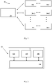
Figure 1 shows an example of a system according to an embodiment of the present invention; -
Figure 2 shows an example of a first computer according to an embodiment of the present invention; -
Figure 3 shows an example of a control device according to an embodiment of the present invention; -
Figure 4 shows an example of a road treatment vehicle according to an embodiment of the present invention; -
Figure 5 show an example of a method according to an embodiment of the present invention; -
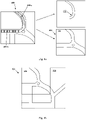
Figures 6a-6c show an example of route information according to an embodiment of the present invention; and -
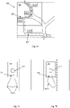
Figures 7a-7b show an example of a spread pattern according to an embodiment of the present invention. -
Figure 1 shows an example of asystem 10 according to an embodiment of the present invention. Thesystem 10 is asystem 10 for communicating road treatment data as will be explained. - The
system 10 comprises afirst computer 100, a plurality of control devices 200-1, 200-2, ..., and 200-n. and a plurality of corresponding road treatment vehicles 300-1, 300-2, ..., and 300-n. In thesystem 10, each control device of the plurality of control devices 200-1, 200-2, ..., and 200-n is associated with a respective treatment vehicle of the plurality of road treatment vehicles 300-1, 300-2, ..., and 300-n. Thefirst computer 100 will be discussed in more detail in relation toFigure 2 . The plurality of control devices 200-1, 200-2, ..., and 200-n will be discussed in more detail in relation toFigure 3 . The plurality of corresponding road treatment vehicles 300-1, 300-2, ..., and 300-n will be discussed in more detail in relation toFigure 4 . - The
first computer 100 is configured to be communicatively connected to the plurality of control devices 200-1, 200-2, ..., and 200-n. The plurality of control devices 200-1, 200-2, ..., and 200-n is configured to be communicatively connected to respective connection means (e.g. connection means 316, discussed below) of the plurality of corresponding road treatment vehicles 300-1, 300-2, .., and 300-n. In some embodiments, auxiliary components, such as a server, may be comprised within thesystem 10 and may be communicatively connected to one or more of thefirst computer 100, the plurality of control devices 200-1, 200-2, ..., and 200-n, and the plurality of corresponding road treatment vehicles. -
Figure 2 shows an example of afirst computer 100. Thefirst computer 100 may be, for example, a user computer, a server, a distributed computing system, or a cloud computing system i.e. formed by one or more remote server computers. Thefirst computer 100 is configured to determine road treatment data comprising route information indicative of a route around a road network to be followed by a road treatment vehicle, and treatment level data indicative of an amount of treatment material to be applied to one or more portions of the route by the road treatment vehicle. Thefirst computer 100 is configured to communicate wirelessly the road treatment data to each of the plurality of control devices 200-1, 200-2, ..., and 200-n, wherein each control device is associated with a respective road treatment vehicle 300-1, 300-2, ..., and 300-n. Thefirst computer 100 may comprise one or more of aninterface unit 102, atransceiver 104, amemory unit 106, and aprocessor 108. - The
interface unit 102 may be configured to receive a user input; for example theinterface unit 102 may comprise one or more of a keyboard, mouse, touchscreen and/or similar. In some examples theuser interface unit 102 may be configured to include other features. - In some embodiments the
transceiver 104 may be comprised of one or moreindividual transceivers 104. Thetransceiver 104 may be configured to transmit and receive information according to a communication protocol, which may be a wireless communication protocol. The wireless communication protocol may utilise radio communication, such as Bluetooth, Wi-Fi, over a wireless cellular network e.g. 4G, 5G etc, or similar. In some examples, thetransceiver 104 may be configured to transmit and receive data using a combination of wired and wireless communication protocols. - The
memory unit 106 may comprise one or more memory devices for storing data therein. Thememory unit 106 may include a volatile memory and/or a non-volatile memory. Thememory unit 106 may, for example, store an instruction or data associated with at least one other components of thefirst computer 100. In some examples, thememory unit 106 may store a software and/or a program. - The
processor 108 may comprise any suitable electronic processor (e.g., a microprocessor, a microcontroller, an ASIC, etc.) that is configured to execute electronic instructions. In some embodiments, theprocessor 108 may access thememory unit 106 and execute and/or use that or those instructions and information to carry out or perform some or all of the functionality and methodology describe herein. -
Figure 3 shows an example of acontrol device 200 from the plurality of control devices 200-1, 200-2, .., 200-n. Thecontrol device 200 is configured to, after receiving the road treatment data from thefirst computer 100, configure the received road treatment data for selection by a user. In some embodiments, thecontrol device 200 comprises one or more of aninterface unit 202, atransceiver 204, amemory unit 206, aprocessor 208, and alocation unit 210. In some embodiments thelocation unit 210 comprises means to determine the geographic location of thecontrol device 200, such as a location determining means configured to use one or more of GLONASS, GPS, Galileo or similar. - In some embodiments, the
control device 200 may be integrated with theroad treatment vehicle 300. For example, thecontrol device 200 may be a unit integrated in or mounted upon a control panel of the road treatment vehicle 300 (e.g. a dashboard console). In some embodiments, thecontrol device 200 may be removeable from theroad treatment vehicle 300. For example, thecontrol device 200 may be a portable unit that may be communicatively connected to theroad treatment vehicle 300, and may be removably connected/integrated into theroad treatment vehicle 300, such as by using a docking station for thecontrol device 200, for example. -
Figure 4 schematically shows an exampleroad treatment vehicle 300 from the plurality of road treatment vehicles 300-1, 300-2, ..., and 300-n. Theroad treatment vehicle 300 may comprise one or more of asensor unit 312, road treatment material deployment means 314, and connection means 316. Thesensor unit 312 may comprise at least one sensor device configured to acquire measurements of the environment of thesensor 312, such as external and/or internal to theroad treatment vehicle 300. For example, thesensor unit 312 may be configured to measure an air temperature, a road surface temperature, an ice thickness, an air pressure, an altitude of the road, a gradient of the road, and/or a humidity of the environment proximal to thevehicle 300. In some embodiments, thesensor unit 312 may be connected to a treatment material reservoir (not illustrated) such as a hopper or liquid storage tank associated with thevehicle 300 to measure an amount of treatment material remaining in the treatment material reservoir. - The road treatment material deployment means 314 may be configured to control the treatment material deployment by the
road treatment vehicle 300. The road treatment material deployment means 314 may comprise, in some embodiments, a deployment device for ejecting solid material e.g. road salt or similar, onto the road surface or one or more nozzles for spraying a liquid material onto the road surface. In some embodiments, the road treatment material deployment means 314 may be configured to deploy the treatment material based on at least one parameter indicating a respective characteristic of the treatment material (e.g. a treatment material spread pattern; an amount of treatment material to be applied, which may be defined in an amount e.g. weight or volume per unit area of the road surface; and a treatment composition, as discussed in more detail below). In some embodiments, the road treatment material deployment means 314 may be configured to be controlled automatically by thecontrol device 200. Thecontrol device 200 may configure one or more parameters associated with the deployment means 314, such as the amount of treatment material to be applied. Thecontrol device 200 may receive data indicative of one or more measurements made by thesensor 312 of theroad treatment vehicle 300, and/or the treatment level data comprised within the road treatment data. - The connection means 316 may comprise a means for commutatively connecting the
road treatment vehicle 300 with thecorresponding control device 200. For example, the connection means may be a transceiver, a docking station, or similar configured to communicate using e.g. Bluetooth or USB-c. -
Figure 5 shows an example of amethod 500 performed bysystem 10. Themethod 500 is of communicating road treatment data to a plurality of control devices 200-1, 200-2, ..., 200-n. - Step 502 comprises determining, at a
first computer 100,road treatment data 600 comprising route information indicative of a route around a road network to be followed by aroad treatment vehicle 300, and treatment level data indicative of an amount of treatment material to be applied to one or more portions of the route by theroad treatment vehicle 300. In other words, theroad treatment data 600 indicates a route to be followed by thevehicle 300 around a road network, and a configuration of the at least one parameter indicating one or more respective characteristics of the treatment material deployment around the route. Theroad treatment data 600 may be determined by one or more of the user of thefirst computer 100 selecting points on a displayed map to determine the route information, identifying road portions of the road network, and determining treatment level data for each road portion of the road network. In some examples, theroad treatment data 600 may be determined based on data indicative of road conditions, data on historical route efficiency, service distance, and/or estimated salt and fuel usage, for example. The data indicative of road conditions may be understood to relate to one or more of an extent and/or severity of ice coverage and/or a road type (e.g. single lane, multiple lane or whether the road includes train/tram lines) to determine the treatment level data for the portions the route. In some examples, the data indicative of road conditions may be collected prior to treatment of a road network. For example, one or more road condition probe vehicles may travel on road portions included in the road network to collect the data indicative of road conditions, using one or more on-board sensors. In some examples, the one or more road condition probe vehicles may comprise one or more of a probe vehicle dedicated to retrieving the data indicative of road conditions (e.g. a "scouting" vehicle); a prior road treatment vehicle from the plurality of road treatment vehicles 300-1, 300-2, ..., and 300-n; or a utility vehicle (e.g. a logistics vehicle and/or a public transport vehicle (e.g. coach/bus) equipped with the one or more sensors that may cover large geographical areas during operation). Historical route efficiency may be understood to relate to how aroad treatment vehicle 300 has travelled a route (e.g. time taken to travel the route, gritting results or similar) and/or how onboard quantities of theroad treatment vehicle 300 are supplied and/or used before, during, and/or after theroad treatment vehicle 300 has travelled the route (e.g. usage of treatment material, supply of treatment material, fuel usage or similar). Taking the supply of treatment material as an example, if aroad treatment vehicle 300 is supplied with an amount of treatment material before travelling a route and theroad treatment vehicle 300 finishes the route still with a large amount of the supplied treatment material remaining, the route efficiency may be considered low because theroad treatment vehicle 300 may have been loaded initially with too much treatment material for the given route. As another example, the historical route efficiency may relate to a time taken for aroad treatment vehicle 300 to travel the route. For example, it may be required that all portions of the route are travelled within a time period or limit. The period of time or time limit may start upon the treatment vehicle passing or leaving a predetermined location. For example, leaving a depot and finish upon completion of the last portion of the route by theroad treatment vehicle 300. This may lead to, for example, only parts of the portions of the route being treated by the road treatment vehicle. In some examples, data relating to the historical route efficiency may be collected during an efficiency-targeting exercise and/or feedback from users of the plurality of road treatment vehicles 300-1, 300-2, ..., and 300-n. - Step 504 comprises communicating wirelessly the road treatment data to each of the plurality of control devices 200-1, 200-2, ..., and 200-n, wherein each
control device 200 is associated with a respectiveroad treatment vehicle 300. Advantageously, by communicating wirelessly the road treatment data to each of the plurality of control devices 200-1, 200-2, ..., and 200-n, each of the control devices 200-1, 200-2, ..., and 200-n of the respective plurality of road treatment vehicles 300-1, 300-2, ..., and 300-n are provided with theroad treatment data 600. thereby removing the requirement for a system to individually communicateroad treatment data 600 to each of thecontrol devices 200. In this way, eachvehicle 300 equipped with one of thecontrol devices 200 stores data indicative of all of the routes communicated to any of the control devices 200-1, 200-2, ..., and 200-n, making each vehicle suitable to service any of the routes. In some embodiments ofstep 504, each control device 200-1, 200-2, ..., and 200-n is arranged to communicate to thefirst computer 100 an indication of the road treatment data being successfully received. - Step 506 comprises configuring the received road treatment data at each of the plurality of control devices 200-1, 200-2, ..., and 200-n for selection by a user. Configuring the received road treatment data at each of the plurality of control devices 200-1, 200-2, ..., and 200-n may comprise installing the road treatment data at each of the
control devices 200. For example, installing the road treatment data at each of thecontrol devices 200 may comprise copying or generating and storing the road treatment data in a road treatment data directory comprised within the memory of each of thecontrol devices 200. Step 506 may comprise in some embodiments reporting, by each of the control devices 200-1, 200-2, ..., and 200-n to thefirst computer 100, an indication of the road treatment data being successfully installed at the respective control device. Advantageously, this may enable a status of each of the plurality of control devices 200-1, 200-2, ..., and 200-n to be determined at thefirst computer 100. In particular, the status is indicative of the road treatment data being installed, and therefore available for selection, at each of the plurality of control devices 200-1, 200-2, ..., and 200-n. - The method comprises receiving, at a control device amongst the plurality of control devices 200-1, 200-2, ..., and 200-n, a user input. The user input is indicative of selected road treatment data. The user input may be received through the
interface unit 202 of thecontrol device 200. For example, the user input may be received through a keyboard, mouse, touchscreen and/or similar of theinterface unit 202. The method comprises outputting an indication of the route around the road network comprised within the selected road treatment data, through theinterface unit 202 of thecontrol device 200. For example, in response to receiving a user input, thecontrol device 202 may output the indication of the route around the road network comprised within the selected road treatment data as is illustrated inFigures 6a ad 6c, as is discussed below. That is, a display of theinterface unit 202 may output the route for a user to view. As such, the user may navigate a road treatment vehicle according to the outputted, selected road treatment data. - In some examples, in response to receiving, at the
control device 200 amongst the plurality of control devices, the user input indicative of the selected road treatment data, thecontrol device 200 may be configured to transmit an acceptance signal to thefirst computer 100. The acceptance signal may indicate the selected road treatment data. In response to receiving the acceptance signal, thefirst computer 100 may be configured to transmit to the remaining control devices amongst the plurality of control devices 200-1, 200-2, ..., and 200-n that the selected road treatment data has been selected by a different control device and is no longer available for selection. Advantageously, the scenario of multiple users selecting the same road treatment data is prevented. Alternatively, users of two or more control devices amongst the plurality of control devices 200-1, 200-2, ..., and 200-n may select the same road treatment data and the respective acceptance signals may indicate the selected road treatment data along with an indication of respective portions of the route that will be travelled by the respective road treatment vehicles associated with the control devices. -
Figure 6a shows an example ofroad treatment data 600. Theroad treatment data 600 comprises route information and treatment level data 608-a, 608-b. The route information is indicative of a route around a road network to be followed by aroad treatment vehicle 300 and the treatment level data 608-a, 608-b is indicative of an amount of treatment material to be applied to one or more portions of the route by theroad treatment vehicle 300. - The route information may comprise
map data 604 androute data 602. Theroute data 602 may indicate the route around the road network to be followed by theroad treatment vehicle 300. For example, the "road network" may be a network of roads which theroad treatment vehicle 300 is directed to travel along. Themap data 604 may indicate the road network in ageographical region 606 corresponding to theroute data 602. Themap data 604 may further indicate a road network corresponding to ageographical region 610 which extends beyond the road network indicated by the route data 602 (e.g.geographical region 610 extending beyond the portion of the road network included in theroute data 602, illustrated inFigure 6b ). That is, themap data 604 may indicate a portion of the road network not included in the route data 602 (e.g. a street neighbouring the road network). In some examples, themap data 604 may indicate thegeographical region 610 beyond the road network up to a predetermined distance from thegeographical region 606 corresponding to theroute data 602. For example, themap data 604 may indicate thegeographical region 610 beyond the road network up to, for example, 1 km (although other distances may be used) away from thegeographical region 606 corresponding to theroute data 602. The predetermined distance may be determined based on one or more of a user input, current road conditions, and the type of environment the road network is located in (e.g. rural or urban). Map data comprising thegeographical region 610 may be indicated to the user of theroad treatment vehicle 300 using interface means 202. Advantageously, thecontrol device 200 of theroad treatment vehicle 300 is provided withmap data 604 in the vicinity of theroute data 602 to enable navigation towards the route indicated by theroute data 602, or aroad treatment vehicle 300 that has deviated from the route indicated by theroute data 602 is provided withmap data 604 to enable navigation back towards the route indicated by theroute data 602. In some examples, when aroad treatment vehicle 300 has deviated from the road network indicated by theroute data 602, thefirst computer 100 may transmit updated data to thecontrol device 200 of theroad treatment vehicle 300. For example, if theroad treatment vehicle 300 deviates from theroute data 602 by more than a predetermined distance, thefirst computer 100 may transmit, to thecontrol device 200, updatedmap data 604 indicating thegeographical region 610 beyond the route network indicated by theroute data 602 so that the user of theroad treatment vehicle 300 may navigate back to the road network to be treated. In some examples, if theroad treatment vehicle 300 continues to deviate from theroute data 602, thefirst computer 100 may transmit, to thecontrol device 200, updated data indicating road treatment data for a different road network so that the user of theroad treatment vehicle 300 may continue deviating from theroute data 602 to treat a different road network. Thecontrol device 200 may configure the received updated data for selection by a user. Thecontrol device 200 may configure the received updated road treatment data in the same way as thecontrol device 200 configures the road treatment data duringstep 506 ofFigure 5 . -
Figure 6c shows an example of route information. In an embodiment, themap data 604 comprised within the route information may comprise at least one topographical identifier, TOID, 612-a to 612-e. Each TOID may indicate a feature of themap data 604. For example, each TOID 612-a to 612-e may have a unique reference identifier used to identify a map feature (e.g. a building, a road, a field, a phone box, a pillar box, and/or a landmark). The route data is indicative of one or more TOIDs forming the route to be followed by thevehicle 300. - In use, a
control device 200 may receive a current location of respectiveroad treatment vehicle 300 using thelocation unit 210 comprised within thecontrol device 200 to determine the current location (e.g. as latitude-longitude coordinates, and/or geocode or similar) of the respective road treatment vehicle, which may be transmitted to controldevice 200 via the connection means 316. Thecontrol device 200 may report the current location of the respectiveroad treatment vehicle 300 to thefirst computer 100. Thecontrol device 200 may report its location periodically e.g. at predetermined time intervals such as 30 seconds, 1 minute or other period. Thus thefirst computer 100 is provided with the location generally continuously and in realtime. Advantageously, a user of thefirst computer 100 may be able to monitor the location of allroad treatment vehicles 300, thereby providing assurance that the users of the plurality of road treatment vehicles 300-1, 300-2, ..., and 300-n are not experiencing issues. For example, thefirst computer 100 may alert a user of thefirst computer 100 if aroad treatment vehicle 300 deviates from a route or stops for any length of time (e.g. if aroad treatment vehicle 300 is involved in a road traffic accident). - The
control device 200 may identify a TOID 612-a to 612-e corresponding to the current location of the respectiveroad treatment vehicle 300. For example, thecontrol device 200 may compare the geographic location of the respectiveroad treatment vehicle 300 with the locations of TOIDs comprised within theroute data 602. - The
control device 200 may determine whether a TOID 612-a to 612-e encountered by therespective treatment vehicle 300 is comprised within theroute data 602. If the number of consecutively encountered TOIDs 612-a to 612-e comprised within theroute data 602 is greater than a predetermined threshold, thecontrol device 200 may automatically select theroad treatment data 600 to be followed by the respectiveroad treatment vehicle 300. In other words, thecontrol device 200 may automatically selectroad treatment data 600 to follow by recognising a route a user is taking by matching encountered TOIDs (e.g. landmarks) to routedata 602 comprising TOIDs (e.g. landmarks). Advantageously, this may enable theroad treatment data 600 to be selected by the user of theroad treatment vehicle 300 without the user having to provide any input to thecontrol device 200 and without the user's attention being taken away from the road, thus improving user safety. - Referring to
Figure 6c as an example, whereinroad treatment data 600 comprises map data 604 (indicating a geographical region 606) and route date 602 (i.e. TOIDs 612-a to 612-b are not included in theroute data 602 and TOIDs 612-c to 612-e are included in the route data 602), if the predetermined threshold is set to a value of two for example, thecontrol device 200 may automatically selectroad treatment data 600 to be followed by theroad treatment vehicle 300 upon theroad treatment vehicle 300 encountering TOID 612-e, when travelling onjourney 614 from point A to point B. - In an embodiment, the predetermined threshold may be determined by one or more of a user of a
control device 200, a user of thefirst computer 100, a user of aroad treatment vehicle 300, thecontrol device 200, and thefirst computer 100. For example, one or more of thecontrol device 200 and thefirst computer 100 may determine the predetermined threshold based on one or more of theroute data 602 and the map data 604 (e.g. the number of TOIDs in a given area). Advantageously, the predetermined threshold may prevent thecontrol device 200 erroneously automatically selecting theroad treatment data 600 to be followed by theroad treatment vehicle 300. - Referring back to
Figure 6a , theroad treatment data 600 comprises treatment level data 608-a, 608-b. The treatment level data 608-a, 608-b may be indicative of an amount of treatment material to be applied to one or more portions of the route by theroad treatment vehicle 300. The treatment level data 608-a, 608-b may be indicative of an amount e.g. weight or volume of treatment material to be applied per unit area of road. The treatment level data 608-a, 608-b may be set at thefirst computer 100 when determining the road treatment data. Treatment level data 608-a, 608-b may be determined based on one or more of meteorological data (e.g. an air temperature and a weather forecast or similar), one or more sensor measurements of thesensor 312, and road usage data. Advantageously, the present invention may determine what type of treatment is most suitable, and to what extent it is most suitable, for different portions of the route, so that the treatment material may be deployed efficiently. For example, meteorological data may indicate a heightened risk of below-freezing temperatures and which roads are more likely to be affected. As another example, a sensor measurement for aroad treatment vehicle 300 altitude may indicate the altitude from sea-level of the portion of the route. Therefore the altitude may be used to determine which portions of the route are more likely to be affected by icy road conditions. As another example, a sensor measurement for a road gradient data may indicate an incline and/or decline of portions of the route. Therefore the gradient may indicate how significant an effect of freezing is likely to be on a road portion (higher gradients mean icing is more dangerous) or how road treatment material is deployed (e.g. in a treatment material spread pattern, discussed below) by the road treatment material deployment means 314. As another example, the road usage data may indicate which roads are most frequently used and therefore are the highest priority to be treated. - The treatment level data 608-a, 608-b may determine how the road treatment material deployment means 314 deploys the treatment material. The treatment level data 608-a, 608-b may comprise at least one parameter indicating a respective characteristic of the treatment material for each of the one or more portions of the route by the
road treatment vehicle 300. In an embodiment, the treatment level data 608-a, 608-b may be indicated to the user of theroad treatment vehicle 300 by way of theinterface unit 202 of thecontrol device 200 in addition to the indication of the route around the road network. - The at least one parameter may comprise one or more of: a treatment material spread pattern; an amount of treatment material to be applied; and a treatment composition. Referring to
Figure 6a , the treatment level data 608-a, 608-b respectively indicate portions of the route comprising different values for the at least one parameter (e.g. treatment level data 608-a may indicate an amount of treatment material of 15g/m2 and treatment level data 608-b may indicate an amount of treatment material of 19 g/m2). - The amount of treatment material may be defined as a weight or volume of the treatment material per unit area of the road surface. The amount of treatment material may be a spread rate uplift indicating a change in the amount of treatment material relative to a previous amount of treatment material determined at the
control device 200. For example, a previous amount of treatment material determined at thecontrol device 200 may be 15 g/m2 and a spread rate uplift may be 4 g/m2, thereby indicating that the amount of treatment material determined at thecontrol device 200 is to be increased by 4 g/m2 relative to 15 g/m2 (i.e. the previous amount of treatment material) to 19g/m2. In some embodiments, the amount of treatment material may be indicative of an absolute amount of treatment material in some examples. For example, the amount of treatment material may be 19g/m2, thereby indicating that the amount of treatment material determined at thecontrol device 200 is to be altered to 19 g/m2. - The previous amount of treatment material may indicate one or more of a previous spread rate uplift and a default amount of treatment material (i.e. a 'base' amount of treatment material). For example the default amount of treatment material may be understood as an amount of treatment material deployed by the road treatment material if the spread rate uplift is 0 g/m2 (e.g. 15g/m2 in the above example). The default amount of treatment material may be determined based on one or more of treatment level data 608-a, 608-b; an input from a user of the
control device 200; and a sensor measurement ofsensor 312 comprised within theroad treatment vehicle 300. - The amount of treatment material may be determined based on one or more of an input from a user of the
control device 200, the treatment level data 608-a, 608-b, and a sensor measurement ofsensor 312 comprised within theroad treatment vehicle 300. For example, a user of theroad treatment vehicle 300 may notice that the driving condition of a portion of the route being travelled by theroad treatment vehicle 300 is different than indicated by the treatment level data 608-a, 608-b (e.g. more ice coverage than expected). In this example, the user may input to one of theroad treatment vehicle 300 and thecontrol device 200 that the amount of treatment material (e.g. the default amount of treatment material) should be changed. As another example, thesensor 312 comprised within theroad treatment vehicle 300 may measure that the road surface temperature is different than that indicated by the amount of treatment material determined at the control device 200 (e.g. road surface may be colder than expected) and thesensor 312 may report the measurement value of the road temperature to thecontrol device 200, which in-turn may determine the spread rate uplift. As another example, once thecontrol device 200 has received the input from the user of theroad treatment vehicle 300 and/or the measurement value from thesensor 312 resulting in a change in the amount of treatment material (i.e. the treatment level data 608-a, 608b), thecontrol device 200 may transmit the change in the amount of treatment material to thefirst computer 100. Thefirst computer 100 may then use the user input and/or sensor measurement value as data of road conditions for determining road treatment data for any road treatment vehicle within the plurality of road treatment vehicles 300-1, 300-2, ..., and 300-n. Advantageously, the determined amount of road treatment material deployed is therefore most suitable for the actual conditions of the road surface, rather than what is most suitable for a forecasted condition of the road surface. While spread rate uplift is changed in the present example, other parameter(s) may be determined using one or more of the user of theroad treatment vehicle 300 and thesensor 312 in other examples. - A treatment material spread pattern may indicate a deployment configuration of the treatment material with respect to the
road treatment vehicle 300. For example, the treatment material spread pattern may indicate a direction in which the treatment material may be deployed. For example, the direction may be: directly behind theroad treatment vehicle 300; towards the right of theroad treatment material 300; or towards the left of theroad treatment material 300, but may not be limited thereto. Advantageously, by directing the road treatment material, theroad treatment vehicle 300 is able to provide a more targeted treatment material spread pattern. For example, theroad treatment vehicle 300 may be controlled to deploy treatment material into a lane next to theroad treatment vehicle 300. The treatment material spread pattern may be indicative of one or more of a treatment spread width 702-a and an asymmetry of the treatment material deployed treatment material 702-b. The treatment spread width 702-a may be understood to describe how wide the deployment of the treatment material is, once deployed. For example, the treatment spread width may be 0.5 m, 1 m, and 2 m, but is not limited thereto. Advantageously, adjusting the treatment spread width 702-a and/or asymmetry 702-b of the treatment material may allow aroad treatment vehicle 300 to accurately deploy the treatment material on a number of different types of road portions and/or road gradients. For example, narrow lanes, dual carriageways, and residential streets may require different treatment spread widths 702-a and asymmetries 702-b in order to be sufficiently treated. Advantageously, by deploying road treatment material with an asymmetry, the road treatment material may prevent unnecessary deployment of treatment material to a specific area in the vicinity of the road treatment vehicle. For example, an asymmetric treatment material deployment configuration may prevent deployment of treatment material on to a side walk adjacent to the road that may be being used by pedestrians. Overall, an accurate spread pattern may reduce bounce when the salt hits the road surface, particularly at higher speeds. - The treatment composition may be indicative of a change in an amount of at least one constituent material used in the treatment material. The at least one constituent material used in the treatment material may be one or more of: a solid constituent and a liquid constituent, wherein a composition comprising at least one solid constituent and at least one liquid constituent may be known as a "pre-wet" composition. The solid constituent may comprise one or more of: a rock salt, a solid chloride salt (e.g. NaCI), and/or an acetate salt or similar. The liquid constituent may comprise one or more of: an aqueous chloride salt (e.g. brine), and/or an aqueous acetate salt or similar. In some examples, an aqueous acetate salt may be comprised within the treatment composition to reduce corrosion when using solid and/or aqueous chloride salt. A change in an amount of the at least one constituent material may comprise at least one of: introducing the at least one constituent material to the treatment material; removing the at least one constituent material from the treatment material; and changing the relative amounts of the at least one constituent material in the treatment material. For example, the change in the amount of at least one constituent material used in the treatment material may introduce a liquid constituent into the dry treatment material (i.e. treatment material consisting only solid constituents), forming a "pre-wet" composition. As another example, the change in the amount of at least one constituent material used in the treatment material may change a relative amount of at least one constituent so that the treatment material transitions from being composed of 70% solid constituent and 30% liquid constituent to being composed of 50% solid constituent and 50% liquid constituent. As yet another example, the change in the amount of at least one constituent material used in the treatment material may introduce further liquid constituents to a "pre-wet" composition (e.g. adding acetate to a "pre-wet" composition). Advantageously, by changing the amount of at least one constituent material used in the treatment material, the present invention may ensure the treatment material being deployed is configured for the respective road surface conditions.
- It will be appreciated that embodiments of the present invention can be realised in the form of hardware, software or a combination of hardware and software. Any such software may be stored in the form of volatile or non-volatile storage such as, for example, a storage device like a ROM, whether erasable or rewritable or not, or in the form of memory such as, for example, RAM, memory chips, device or integrated circuits or on an optically or magnetically readable medium such as, for example, a CD, DVD, magnetic disk or magnetic tape. It will be appreciated that the storage devices and storage media are embodiments of machine-readable storage that are suitable for storing a program or programs that, when executed, implement embodiments of the present invention. Accordingly, embodiments provide a program comprising code for implementing a system or method as claimed in any preceding claim and a machine readable storage storing such a program. Still further, embodiments of the present invention may be conveyed electronically via any medium such as a communication signal carried over a wired or wireless connection and embodiments suitably encompass the same.
- All of the features disclosed in this specification (including any accompanying claims, abstract and drawings), and/or all of the steps of any method or process so disclosed, may be combined in any combination, except combinations where at least some of such features and/or steps are mutually exclusive.
- Each feature disclosed in this specification (including any accompanying claims, abstract and drawings), may be replaced by alternative features serving the same, equivalent or similar purpose, unless expressly stated otherwise. Thus, unless expressly stated otherwise, each feature disclosed is one example only of a generic series of equivalent or similar features.
- The invention is not restricted to the details of any foregoing embodiments. The invention extends to any novel one, or any novel combination, of the features disclosed in this specification (including any accompanying claims, abstract and drawings), or to any novel one, or any novel combination, of the steps of any method or process so disclosed. The claims should not be construed to cover merely the foregoing embodiments, but also any embodiments which fall within the scope of the claims.
Claims (15)
- A method of communicating road treatment data to a plurality of control devices each associated with a road treatment vehicle, comprising:determining, at a first computer, road treatment data comprising route information indicative of a route around a road network to be followed by one of the road treatment vehicles, and treatment level data indicative of an amount of treatment material to be applied to one or more portions of the route by the road treatment vehicle;communicating wirelessly the road treatment data to each of the plurality of control devices;configuring the received road treatment data at each of the plurality of control devices for selection by a user; andreceiving, at a control device amongst the plurality of control devices, a user input indicative of selected road treatment data, and outputting an indication of the route around the road network comprised within the selected road treatment data, through an interface unit of the control device.
- The method of claim 1, wherein the configuring the received road treatment data at each of the plurality of control devices comprises:installing the road treatment data at each of the control devices; andreporting, by each of the control devices to the first computer, an indication of the road treatment data being successfully installed at the respective control device.
- The method of any preceding claim, wherein the route information comprises:
map data and route data, the route data indicating the route around the road network to be followed by the road treatment vehicle and the map data indicating a road network in a geographical region corresponding to the route data. - The method of claim 3, wherein the map data is indicative of the road network corresponding to a geographical region which extends beyond the road network indicated by the route data.
- The method of claims 3-4, wherein the map data comprises:
at least one topographic identifier, TOID, indicating a feature of the map data. - The method of claim 5, further comprising:receiving, by a control device, a current location of a respective road treatment vehicle;identifying, by the control device, a TOID corresponding to the current location of the respective road treatment vehicle;determining, by the control device, whether the TOID encountered by the respective road treatment vehicle, is comprised within the route data; and,if the number of consecutively encountered TOIDs comprised within the route data is greater than a predetermined threshold, automatically selecting, by the control device, the road treatment data to be followed by the respective road treatment vehicle.
- The method of any preceding claim, wherein the treatment level data comprises at least one parameter indicating a respective characteristic of the treatment material for each of the one or more portions of the route by the road treatment vehicle.
- The method of claim 7, wherein the at least one parameter comprises one or more of a treatment material spread pattern, an amount of treatment material to be applied, and a treatment composition.
- The method of claim 8, wherein the amount of treatment material to be applied is a spread rate uplift indicating a change in the amount of treatment material relative to a previous amount of treatment material determined at the control device.
- The method of claim 8, wherein the amount of treatment material indicates an absolute amount of treatment material.
- The method of claims 8-10, wherein the amount of treatment material is determined based on one or more of an input from a user of the control device, the treatment level data, and a sensor measurement of a sensor comprised within the road treatment vehicle.
- The method of claim 8 or 9, wherein the treatment composition indicates a change in an amount of at least one constituent material used in the treatment material.
- The method of claim 8, wherein the treatment material spread pattern is indicative of a deployment configuration of the treatment material with respect to the road treatment vehicle.
- The method of claim 13, wherein the treatment material spread pattern is indicative of one or more of a treatment spread width and an asymmetry of treatment material deployment.
- The method of any preceding claim, wherein the first computer is one of a user computer, a server, a distributed computing system, and a cloud computing system.
Applications Claiming Priority (1)
| Application Number | Priority Date | Filing Date | Title |
|---|---|---|---|
| GB2108980.0A GB2608138A (en) | 2021-06-23 | 2021-06-23 | Method and system for communicating road treatment data |
Publications (2)
| Publication Number | Publication Date |
|---|---|
| EP4113066A1 true EP4113066A1 (en) | 2023-01-04 |
| EP4113066B1 EP4113066B1 (en) | 2025-08-06 |
Family
ID=77050548
Family Applications (1)
| Application Number | Title | Priority Date | Filing Date |
|---|---|---|---|
| EP22180793.6A Active EP4113066B1 (en) | 2021-06-23 | 2022-06-23 | Method and system for communicating road treatment data |
Country Status (2)
| Country | Link |
|---|---|
| EP (1) | EP4113066B1 (en) |
| GB (1) | GB2608138A (en) |
Citations (5)
| Publication number | Priority date | Publication date | Assignee | Title |
|---|---|---|---|---|
| US20090198421A1 (en) * | 2004-10-13 | 2009-08-06 | Jesper Malm Barfod | Vehicle for spreading products on a road surface |
| US20110298638A1 (en) * | 2010-06-02 | 2011-12-08 | Concaten Inc. | Distributed maintenance decision and support system and method |
| JP2012103985A (en) * | 2010-11-11 | 2012-05-31 | Yazaki Corp | Vehicle information collecting device, vehicle information collecting system and vehicle information collecting method |
| US20140067265A1 (en) * | 2012-08-28 | 2014-03-06 | Cvg Management Corporation | Road condition tracking and presentation |
| US20190293442A1 (en) * | 2018-03-23 | 2019-09-26 | Ford Global Technologies, Llc | Vehicle route planning |
Family Cites Families (2)
| Publication number | Priority date | Publication date | Assignee | Title |
|---|---|---|---|---|
| GB9520478D0 (en) * | 1995-10-06 | 1995-12-06 | West Glamorgan County Council | Monitoring system |
| IT201900014871A1 (en) * | 2019-08-20 | 2021-02-20 | Giletta Spa | METHOD AND SYSTEM FOR THE TREATMENT OF A ROAD SURFACE BY MEANS OF AN INDUSTRIAL VEHICLE |
-
2021
- 2021-06-23 GB GB2108980.0A patent/GB2608138A/en active Pending
-
2022
- 2022-06-23 EP EP22180793.6A patent/EP4113066B1/en active Active
Patent Citations (5)
| Publication number | Priority date | Publication date | Assignee | Title |
|---|---|---|---|---|
| US20090198421A1 (en) * | 2004-10-13 | 2009-08-06 | Jesper Malm Barfod | Vehicle for spreading products on a road surface |
| US20110298638A1 (en) * | 2010-06-02 | 2011-12-08 | Concaten Inc. | Distributed maintenance decision and support system and method |
| JP2012103985A (en) * | 2010-11-11 | 2012-05-31 | Yazaki Corp | Vehicle information collecting device, vehicle information collecting system and vehicle information collecting method |
| US20140067265A1 (en) * | 2012-08-28 | 2014-03-06 | Cvg Management Corporation | Road condition tracking and presentation |
| US20190293442A1 (en) * | 2018-03-23 | 2019-09-26 | Ford Global Technologies, Llc | Vehicle route planning |
Also Published As
| Publication number | Publication date |
|---|---|
| GB202108980D0 (en) | 2021-08-04 |
| GB2608138A (en) | 2022-12-28 |
| EP4113066B1 (en) | 2025-08-06 |
Similar Documents
| Publication | Publication Date | Title |
|---|---|---|
| EP3560783B1 (en) | Road surface condition estimation apparatus and road surface condition estimation method | |
| EP0835962B1 (en) | Vehicle for spreading products on the road surface, in particular de-icing products | |
| US6154699A (en) | Gritting systems and methods | |
| JP3434429B2 (en) | Railway navigation system and method for determining railroad track identifiers | |
| CN114096804B (en) | Map data generation system, data center and vehicle-mounted device | |
| WO2023129648A2 (en) | Systems and methods for vehicle control using terrain-based localization | |
| JP4840069B2 (en) | Navigation system | |
| CN111942382B (en) | Automatic driving assistance system | |
| US12589751B2 (en) | Systems and methods for vehicle control using terrain-based localization | |
| JP3500024B2 (en) | Vehicle control method in automatic driving system | |
| CN109313033B (en) | Updating of navigation data | |
| CN117606494A (en) | Method for predicting future driving conditions of a vehicle | |
| EP2732240B1 (en) | Managing errors in geographical data | |
| JP2007033331A (en) | Route-searching device and method, navigation device and system providing the route-searching device, and route-searching computer program | |
| US20110320113A1 (en) | Generating driving route traces in a navigation system using a probability model | |
| CN103988239A (en) | Operation management system of mining machinery and operation management method of mining machinery | |
| EP2789980B1 (en) | Planning of driving and driving interruptions based on points of interest | |
| US20180209120A1 (en) | Surveying system and method using mobile work machine | |
| CN110562264A (en) | Road hazard prediction method, device, equipment and medium for driverless driving | |
| DE112015000924T5 (en) | Target-dependent speed controller | |
| JP7007836B2 (en) | Work status display control device, work status display control system, and program | |
| JP2022088175A (en) | Information processing device, information processing system, information processing method, and program | |
| EP4113066B1 (en) | Method and system for communicating road treatment data | |
| CN114754790B (en) | A multi-map navigation method, system and storage medium | |
| JP4814142B2 (en) | Link travel time calculation device |
Legal Events
| Date | Code | Title | Description |
|---|---|---|---|
| PUAI | Public reference made under article 153(3) epc to a published international application that has entered the european phase |
Free format text: ORIGINAL CODE: 0009012 |
|
| STAA | Information on the status of an ep patent application or granted ep patent |
Free format text: STATUS: THE APPLICATION HAS BEEN PUBLISHED |
|
| AK | Designated contracting states |
Kind code of ref document: A1 Designated state(s): AL AT BE BG CH CY CZ DE DK EE ES FI FR GB GR HR HU IE IS IT LI LT LU LV MC MK MT NL NO PL PT RO RS SE SI SK SM TR |
|
| STAA | Information on the status of an ep patent application or granted ep patent |
Free format text: STATUS: REQUEST FOR EXAMINATION WAS MADE |
|
| 17P | Request for examination filed |
Effective date: 20230704 |
|
| RBV | Designated contracting states (corrected) |
Designated state(s): AL AT BE BG CH CY CZ DE DK EE ES FI FR GB GR HR HU IE IS IT LI LT LU LV MC MK MT NL NO PL PT RO RS SE SI SK SM TR |
|
| STAA | Information on the status of an ep patent application or granted ep patent |
Free format text: STATUS: EXAMINATION IS IN PROGRESS |
|
| 17Q | First examination report despatched |
Effective date: 20240104 |
|
| RIC1 | Information provided on ipc code assigned before grant |
Ipc: G06Q 50/40 20240101ALI20250121BHEP Ipc: G08G 1/0968 20060101ALI20250121BHEP Ipc: G08G 1/0967 20060101ALI20250121BHEP Ipc: G08G 1/01 20060101ALI20250121BHEP Ipc: G06Q 50/26 20120101ALI20250121BHEP Ipc: G06Q 10/0631 20230101ALI20250121BHEP Ipc: G06Q 10/047 20230101ALI20250121BHEP Ipc: E01C 19/20 20060101ALI20250121BHEP Ipc: E01H 10/00 20060101ALI20250121BHEP Ipc: G08G 1/00 20060101ALI20250121BHEP Ipc: G01C 21/36 20060101ALI20250121BHEP Ipc: G01C 21/34 20060101AFI20250121BHEP |
|
| GRAP | Despatch of communication of intention to grant a patent |
Free format text: ORIGINAL CODE: EPIDOSNIGR1 |
|
| STAA | Information on the status of an ep patent application or granted ep patent |
Free format text: STATUS: GRANT OF PATENT IS INTENDED |
|
| INTG | Intention to grant announced |
Effective date: 20250311 |
|
| P01 | Opt-out of the competence of the unified patent court (upc) registered |
Free format text: CASE NUMBER: APP_19288/2025 Effective date: 20250422 |
|
| GRAS | Grant fee paid |
Free format text: ORIGINAL CODE: EPIDOSNIGR3 |
|
| GRAA | (expected) grant |
Free format text: ORIGINAL CODE: 0009210 |
|
| STAA | Information on the status of an ep patent application or granted ep patent |
Free format text: STATUS: THE PATENT HAS BEEN GRANTED |
|
| AK | Designated contracting states |
Kind code of ref document: B1 Designated state(s): AL AT BE BG CH CY CZ DE DK EE ES FI FR GB GR HR HU IE IS IT LI LT LU LV MC MK MT NL NO PL PT RO RS SE SI SK SM TR |
|
| REG | Reference to a national code |
Ref country code: GB Ref legal event code: FG4D |
|
| REG | Reference to a national code |
Ref country code: CH Ref legal event code: EP |
|
| REG | Reference to a national code |
Ref country code: IE Ref legal event code: FG4D |
|
| REG | Reference to a national code |
Ref country code: DE Ref legal event code: R096 Ref document number: 602022018781 Country of ref document: DE |
|
| REG | Reference to a national code |
Ref country code: NL Ref legal event code: MP Effective date: 20250806 |
|
| PG25 | Lapsed in a contracting state [announced via postgrant information from national office to epo] |
Ref country code: IS Free format text: LAPSE BECAUSE OF FAILURE TO SUBMIT A TRANSLATION OF THE DESCRIPTION OR TO PAY THE FEE WITHIN THE PRESCRIBED TIME-LIMIT Effective date: 20251206 |
|
| PG25 | Lapsed in a contracting state [announced via postgrant information from national office to epo] |
Ref country code: NO Free format text: LAPSE BECAUSE OF FAILURE TO SUBMIT A TRANSLATION OF THE DESCRIPTION OR TO PAY THE FEE WITHIN THE PRESCRIBED TIME-LIMIT Effective date: 20251106 |
|
| REG | Reference to a national code |
Ref country code: LT Ref legal event code: MG9D |
|
| PG25 | Lapsed in a contracting state [announced via postgrant information from national office to epo] |
Ref country code: PT Free format text: LAPSE BECAUSE OF FAILURE TO SUBMIT A TRANSLATION OF THE DESCRIPTION OR TO PAY THE FEE WITHIN THE PRESCRIBED TIME-LIMIT Effective date: 20251209 |
|
| PG25 | Lapsed in a contracting state [announced via postgrant information from national office to epo] |
Ref country code: FI Free format text: LAPSE BECAUSE OF FAILURE TO SUBMIT A TRANSLATION OF THE DESCRIPTION OR TO PAY THE FEE WITHIN THE PRESCRIBED TIME-LIMIT Effective date: 20250806 |
|
| PG25 | Lapsed in a contracting state [announced via postgrant information from national office to epo] |
Ref country code: HR Free format text: LAPSE BECAUSE OF FAILURE TO SUBMIT A TRANSLATION OF THE DESCRIPTION OR TO PAY THE FEE WITHIN THE PRESCRIBED TIME-LIMIT Effective date: 20250806 Ref country code: NL Free format text: LAPSE BECAUSE OF FAILURE TO SUBMIT A TRANSLATION OF THE DESCRIPTION OR TO PAY THE FEE WITHIN THE PRESCRIBED TIME-LIMIT Effective date: 20250806 |
|
| PG25 | Lapsed in a contracting state [announced via postgrant information from national office to epo] |
Ref country code: GR Free format text: LAPSE BECAUSE OF FAILURE TO SUBMIT A TRANSLATION OF THE DESCRIPTION OR TO PAY THE FEE WITHIN THE PRESCRIBED TIME-LIMIT Effective date: 20251107 |
|
| PG25 | Lapsed in a contracting state [announced via postgrant information from national office to epo] |
Ref country code: SE Free format text: LAPSE BECAUSE OF FAILURE TO SUBMIT A TRANSLATION OF THE DESCRIPTION OR TO PAY THE FEE WITHIN THE PRESCRIBED TIME-LIMIT Effective date: 20250806 |
|
| PG25 | Lapsed in a contracting state [announced via postgrant information from national office to epo] |
Ref country code: LV Free format text: LAPSE BECAUSE OF FAILURE TO SUBMIT A TRANSLATION OF THE DESCRIPTION OR TO PAY THE FEE WITHIN THE PRESCRIBED TIME-LIMIT Effective date: 20250806 |
|
| PG25 | Lapsed in a contracting state [announced via postgrant information from national office to epo] |
Ref country code: BG Free format text: LAPSE BECAUSE OF FAILURE TO SUBMIT A TRANSLATION OF THE DESCRIPTION OR TO PAY THE FEE WITHIN THE PRESCRIBED TIME-LIMIT Effective date: 20250806 Ref country code: PL Free format text: LAPSE BECAUSE OF FAILURE TO SUBMIT A TRANSLATION OF THE DESCRIPTION OR TO PAY THE FEE WITHIN THE PRESCRIBED TIME-LIMIT Effective date: 20250806 |
|
| PG25 | Lapsed in a contracting state [announced via postgrant information from national office to epo] |
Ref country code: RS Free format text: LAPSE BECAUSE OF FAILURE TO SUBMIT A TRANSLATION OF THE DESCRIPTION OR TO PAY THE FEE WITHIN THE PRESCRIBED TIME-LIMIT Effective date: 20251106 |
|
| PG25 | Lapsed in a contracting state [announced via postgrant information from national office to epo] |
Ref country code: ES Free format text: LAPSE BECAUSE OF FAILURE TO SUBMIT A TRANSLATION OF THE DESCRIPTION OR TO PAY THE FEE WITHIN THE PRESCRIBED TIME-LIMIT Effective date: 20250806 |
|
| REG | Reference to a national code |
Ref country code: AT Ref legal event code: MK05 Ref document number: 1822320 Country of ref document: AT Kind code of ref document: T Effective date: 20250806 |
|
| PG25 | Lapsed in a contracting state [announced via postgrant information from national office to epo] |
Ref country code: SM Free format text: LAPSE BECAUSE OF FAILURE TO SUBMIT A TRANSLATION OF THE DESCRIPTION OR TO PAY THE FEE WITHIN THE PRESCRIBED TIME-LIMIT Effective date: 20250806 |
|
| PG25 | Lapsed in a contracting state [announced via postgrant information from national office to epo] |
Ref country code: DK Free format text: LAPSE BECAUSE OF FAILURE TO SUBMIT A TRANSLATION OF THE DESCRIPTION OR TO PAY THE FEE WITHIN THE PRESCRIBED TIME-LIMIT Effective date: 20250806 |
|
| PG25 | Lapsed in a contracting state [announced via postgrant information from national office to epo] |
Ref country code: AT Free format text: LAPSE BECAUSE OF FAILURE TO SUBMIT A TRANSLATION OF THE DESCRIPTION OR TO PAY THE FEE WITHIN THE PRESCRIBED TIME-LIMIT Effective date: 20250806 |
|
| PG25 | Lapsed in a contracting state [announced via postgrant information from national office to epo] |
Ref country code: IT Free format text: LAPSE BECAUSE OF FAILURE TO SUBMIT A TRANSLATION OF THE DESCRIPTION OR TO PAY THE FEE WITHIN THE PRESCRIBED TIME-LIMIT Effective date: 20250806 |
|
| PG25 | Lapsed in a contracting state [announced via postgrant information from national office to epo] |
Ref country code: CZ Free format text: LAPSE BECAUSE OF FAILURE TO SUBMIT A TRANSLATION OF THE DESCRIPTION OR TO PAY THE FEE WITHIN THE PRESCRIBED TIME-LIMIT Effective date: 20250806 |
|
| PG25 | Lapsed in a contracting state [announced via postgrant information from national office to epo] |
Ref country code: EE Free format text: LAPSE BECAUSE OF FAILURE TO SUBMIT A TRANSLATION OF THE DESCRIPTION OR TO PAY THE FEE WITHIN THE PRESCRIBED TIME-LIMIT Effective date: 20250806 Ref country code: SK Free format text: LAPSE BECAUSE OF FAILURE TO SUBMIT A TRANSLATION OF THE DESCRIPTION OR TO PAY THE FEE WITHIN THE PRESCRIBED TIME-LIMIT Effective date: 20250806 |