EP4113038A1 - Air conditioner, control method, and program - Google Patents
Air conditioner, control method, and program Download PDFInfo
- Publication number
- EP4113038A1 EP4113038A1 EP21780480.6A EP21780480A EP4113038A1 EP 4113038 A1 EP4113038 A1 EP 4113038A1 EP 21780480 A EP21780480 A EP 21780480A EP 4113038 A1 EP4113038 A1 EP 4113038A1
- Authority
- EP
- European Patent Office
- Prior art keywords
- refrigerant
- air conditioner
- valve
- receiver
- condenser
- Prior art date
- Legal status (The legal status is an assumption and is not a legal conclusion. Google has not performed a legal analysis and makes no representation as to the accuracy of the status listed.)
- Pending
Links
Images



Classifications
-
- F—MECHANICAL ENGINEERING; LIGHTING; HEATING; WEAPONS; BLASTING
- F25—REFRIGERATION OR COOLING; COMBINED HEATING AND REFRIGERATION SYSTEMS; HEAT PUMP SYSTEMS; MANUFACTURE OR STORAGE OF ICE; LIQUEFACTION SOLIDIFICATION OF GASES
- F25B—REFRIGERATION MACHINES, PLANTS OR SYSTEMS; COMBINED HEATING AND REFRIGERATION SYSTEMS; HEAT PUMP SYSTEMS
- F25B49/00—Arrangement or mounting of control or safety devices
- F25B49/02—Arrangement or mounting of control or safety devices for compression type machines, plants or systems
-
- F—MECHANICAL ENGINEERING; LIGHTING; HEATING; WEAPONS; BLASTING
- F25—REFRIGERATION OR COOLING; COMBINED HEATING AND REFRIGERATION SYSTEMS; HEAT PUMP SYSTEMS; MANUFACTURE OR STORAGE OF ICE; LIQUEFACTION SOLIDIFICATION OF GASES
- F25B—REFRIGERATION MACHINES, PLANTS OR SYSTEMS; COMBINED HEATING AND REFRIGERATION SYSTEMS; HEAT PUMP SYSTEMS
- F25B13/00—Compression machines, plants or systems, with reversible cycle
-
- F—MECHANICAL ENGINEERING; LIGHTING; HEATING; WEAPONS; BLASTING
- F25—REFRIGERATION OR COOLING; COMBINED HEATING AND REFRIGERATION SYSTEMS; HEAT PUMP SYSTEMS; MANUFACTURE OR STORAGE OF ICE; LIQUEFACTION SOLIDIFICATION OF GASES
- F25B—REFRIGERATION MACHINES, PLANTS OR SYSTEMS; COMBINED HEATING AND REFRIGERATION SYSTEMS; HEAT PUMP SYSTEMS
- F25B41/00—Fluid-circulation arrangements
- F25B41/20—Disposition of valves, e.g. of on-off valves or flow control valves
-
- F—MECHANICAL ENGINEERING; LIGHTING; HEATING; WEAPONS; BLASTING
- F25—REFRIGERATION OR COOLING; COMBINED HEATING AND REFRIGERATION SYSTEMS; HEAT PUMP SYSTEMS; MANUFACTURE OR STORAGE OF ICE; LIQUEFACTION SOLIDIFICATION OF GASES
- F25B—REFRIGERATION MACHINES, PLANTS OR SYSTEMS; COMBINED HEATING AND REFRIGERATION SYSTEMS; HEAT PUMP SYSTEMS
- F25B45/00—Arrangements for charging or discharging refrigerant
-
- F—MECHANICAL ENGINEERING; LIGHTING; HEATING; WEAPONS; BLASTING
- F25—REFRIGERATION OR COOLING; COMBINED HEATING AND REFRIGERATION SYSTEMS; HEAT PUMP SYSTEMS; MANUFACTURE OR STORAGE OF ICE; LIQUEFACTION SOLIDIFICATION OF GASES
- F25B—REFRIGERATION MACHINES, PLANTS OR SYSTEMS; COMBINED HEATING AND REFRIGERATION SYSTEMS; HEAT PUMP SYSTEMS
- F25B49/00—Arrangement or mounting of control or safety devices
- F25B49/005—Arrangement or mounting of control or safety devices of safety devices
-
- F—MECHANICAL ENGINEERING; LIGHTING; HEATING; WEAPONS; BLASTING
- F24—HEATING; RANGES; VENTILATING
- F24F—AIR-CONDITIONING; AIR-HUMIDIFICATION; VENTILATION; USE OF AIR CURRENTS FOR SCREENING
- F24F11/00—Control or safety arrangements
- F24F11/30—Control or safety arrangements for purposes related to the operation of the system, e.g. for safety or monitoring
- F24F11/32—Responding to malfunctions or emergencies
- F24F11/36—Responding to malfunctions or emergencies to leakage of heat-exchange fluid
-
- F—MECHANICAL ENGINEERING; LIGHTING; HEATING; WEAPONS; BLASTING
- F25—REFRIGERATION OR COOLING; COMBINED HEATING AND REFRIGERATION SYSTEMS; HEAT PUMP SYSTEMS; MANUFACTURE OR STORAGE OF ICE; LIQUEFACTION SOLIDIFICATION OF GASES
- F25B—REFRIGERATION MACHINES, PLANTS OR SYSTEMS; COMBINED HEATING AND REFRIGERATION SYSTEMS; HEAT PUMP SYSTEMS
- F25B2400/00—Component parts or details not otherwise provided for in this subclass
- F25B2400/16—Receivers
-
- F—MECHANICAL ENGINEERING; LIGHTING; HEATING; WEAPONS; BLASTING
- F25—REFRIGERATION OR COOLING; COMBINED HEATING AND REFRIGERATION SYSTEMS; HEAT PUMP SYSTEMS; MANUFACTURE OR STORAGE OF ICE; LIQUEFACTION SOLIDIFICATION OF GASES
- F25B—REFRIGERATION MACHINES, PLANTS OR SYSTEMS; COMBINED HEATING AND REFRIGERATION SYSTEMS; HEAT PUMP SYSTEMS
- F25B2400/00—Component parts or details not otherwise provided for in this subclass
- F25B2400/19—Pumping down refrigerant from one part of the cycle to another part of the cycle, e.g. when the cycle is changed from cooling to heating, or before a defrost cycle is started
-
- F—MECHANICAL ENGINEERING; LIGHTING; HEATING; WEAPONS; BLASTING
- F25—REFRIGERATION OR COOLING; COMBINED HEATING AND REFRIGERATION SYSTEMS; HEAT PUMP SYSTEMS; MANUFACTURE OR STORAGE OF ICE; LIQUEFACTION SOLIDIFICATION OF GASES
- F25B—REFRIGERATION MACHINES, PLANTS OR SYSTEMS; COMBINED HEATING AND REFRIGERATION SYSTEMS; HEAT PUMP SYSTEMS
- F25B2500/00—Problems to be solved
- F25B2500/22—Preventing, detecting or repairing leaks of refrigeration fluids
- F25B2500/222—Detecting refrigerant leaks
-
- F—MECHANICAL ENGINEERING; LIGHTING; HEATING; WEAPONS; BLASTING
- F25—REFRIGERATION OR COOLING; COMBINED HEATING AND REFRIGERATION SYSTEMS; HEAT PUMP SYSTEMS; MANUFACTURE OR STORAGE OF ICE; LIQUEFACTION SOLIDIFICATION OF GASES
- F25B—REFRIGERATION MACHINES, PLANTS OR SYSTEMS; COMBINED HEATING AND REFRIGERATION SYSTEMS; HEAT PUMP SYSTEMS
- F25B2600/00—Control issues
- F25B2600/25—Control of valves
- F25B2600/2523—Receiver valves
-
- F—MECHANICAL ENGINEERING; LIGHTING; HEATING; WEAPONS; BLASTING
- F25—REFRIGERATION OR COOLING; COMBINED HEATING AND REFRIGERATION SYSTEMS; HEAT PUMP SYSTEMS; MANUFACTURE OR STORAGE OF ICE; LIQUEFACTION SOLIDIFICATION OF GASES
- F25B—REFRIGERATION MACHINES, PLANTS OR SYSTEMS; COMBINED HEATING AND REFRIGERATION SYSTEMS; HEAT PUMP SYSTEMS
- F25B2700/00—Sensing or detecting of parameters; Sensors therefor
- F25B2700/21—Temperatures
- F25B2700/2108—Temperatures of a receiver
-
- F—MECHANICAL ENGINEERING; LIGHTING; HEATING; WEAPONS; BLASTING
- F25—REFRIGERATION OR COOLING; COMBINED HEATING AND REFRIGERATION SYSTEMS; HEAT PUMP SYSTEMS; MANUFACTURE OR STORAGE OF ICE; LIQUEFACTION SOLIDIFICATION OF GASES
- F25B—REFRIGERATION MACHINES, PLANTS OR SYSTEMS; COMBINED HEATING AND REFRIGERATION SYSTEMS; HEAT PUMP SYSTEMS
- F25B2700/00—Sensing or detecting of parameters; Sensors therefor
- F25B2700/21—Temperatures
- F25B2700/2115—Temperatures of a compressor or the drive means therefor
- F25B2700/21152—Temperatures of a compressor or the drive means therefor at the discharge side of the compressor
Definitions
- the present disclosure relates to an air conditioner, a control method, and a program.
- PTL 1 discloses, as a related technique, a technique relating to a refrigerating cycle device for storing a refrigerant such that a pipe having a low design pressure can be used.
- An object of the present disclosure is to provide an air conditioner, a control method and a program capable of solving the above-described problems.
- an air conditioner includes: a condenser that condenses a refrigerant; an evaporator that evaporates the condensed refrigerant; a compressor that compresses the evaporated refrigerant; a receiver capable of recovering the compressed refrigerant; and a switching valve capable of switching a discharge destination of the compressed refrigerant from the condenser to the receiver.
- a control method performed by an air conditioner including a condenser that condenses a refrigerant, an evaporator that evaporates the condensed refrigerant, a compressor that compresses the evaporated refrigerant, a receiver capable of recovering the compressed refrigerant, and a switching valve capable of switching a discharge destination of the compressed refrigerant from the condenser to the receiver, the method including: controlling a flow path in the switching valve.
- a program causes a computer in an air conditioner to control a flow path in a switching valve, the air conditioner including a condenser that condenses a refrigerant, an evaporator that evaporates the condensed refrigerant, a compressor that compresses the evaporated refrigerant, a receiver capable of recovering the compressed refrigerant, and the switching valve capable of switching a discharge destination of the compressed refrigerant from the condenser to the receiver.
- the leakage when the refrigerant leaks in the air conditioner, the leakage can be reduced.
- the air conditioner 1 is an air conditioner that recovers the refrigerant in the receiver, when the leakage of the refrigerant from the air conditioner is detected.
- the air conditioner 1 includes an outdoor unit 10, an indoor unit 20, and a control device 30.
- the air conditioner 1 will be described by using the operation during the cooling operation as an example (that is, by using the case of operating as a refrigerating cycle device as an example) among the heating and cooling operations of the air conditioner 1, and the operation during the heating operation will be described at the end of the first embodiment.
- the outdoor unit 10 includes a compressor 101, an accumulator 102, a switching valve 103 (an example of a switching valve), a four-way valve 104, a blower fan 105, a heat exchanger 106 (an example of a condenser, an example of a compressor), a throttle mechanism 107 (an example of an expansion valve), a check valve 108, a receiver 109, an on/off valve 110, a discharge temperature sensor 111, a receiver temperature sensor 112, and a gas sensor 113 (an example of a gas sensor).
- the compressor 101 is a device that compresses a gaseous refrigerant.
- the refrigerant compressed by the compressor 101 is normally sent to the heat exchanger 106 via the switching valve 103 and the four-way valve 104.
- the accumulator 102 is a device that separates a liquid refrigerant and a gaseous refrigerant. Only the gaseous refrigerant among the refrigerants separated by the accumulator 102 is sent to the compressor 101.
- the switching valve 103 is a valve that switches the destination of the refrigerant discharged from the compressor 101.
- the switching valve 103 normally sets the destination of the refrigerant discharged from the compressor 101 to the heat exchanger 106. Further, when the leakage of the refrigerant is detected, the switching valve 103 uses the receiver 109 as the destination of the refrigerant discharged from the compressor 101.
- the four-way valve 104 is a valve that switches between a cooling operation and a heating operation of the air conditioner 1.
- the four-way valve 104 uses the heat exchanger 106 as the destination of the refrigerant discharged from the compressor 101, during the cooling operation of the air conditioner 1.
- the destination of the refrigerant is the heat exchanger 201.
- the blower fan 105 is a fan that sends air to the heat exchanger 106.
- the heat exchanger 106 operates as a condenser during the cooling operation of the air conditioner 1. That is, the gaseous refrigerant exchanges heat with the air sent by the blower fan 105 and becomes a liquid refrigerant. The liquid refrigerant in the heat exchanger 106 is sent to the throttle mechanism 107.
- the throttle mechanism 107 includes a mechanism for reducing the pressure of the refrigerant and expanding the refrigerant.
- the throttle mechanism 107 reduces the temperature of the refrigerant.
- the throttle mechanism 107 is provided between the heat exchanger 106 and the heat exchanger 201, which will be described later.
- the throttle mechanism 107 is, for example, an electronic expansion valve.
- the check valve 108 is a valve that prevents the backflow of the refrigerant. For example, when leakage of a refrigerant is detected and the receiver 109 is set as the destination of the refrigerant discharged from the compressor 101 by the switching valve 103, the check valve 108 sends the refrigerant only in the direction from the compressor 101 to the receiver 109.
- the receiver 109 is a container that recovers and stores the refrigerant inside, when the leakage of the refrigerant is detected.
- the on/off valve 110 is a valve that opens and closes the flow path of the refrigerant.
- the on/off valve 110 is an electromagnetic valve.
- the discharge temperature sensor 111 is a sensor that measures the temperature in the refrigerant discharge unit of the compressor 101.
- the discharge temperature sensor 111 is provided in the refrigerant discharge unit of the compressor 101.
- the receiver temperature sensor 112 is a sensor that measures the temperature at the receiver 109.
- the receiver temperature sensor 112 is provided above the receiver 109.
- the gas sensor 113 is a sensor that detects a gaseous refrigerant.
- the gas sensor 113 is provided in the vicinity of the heat exchanger 106.
- the indoor unit 20 includes a heat exchanger 201 (an example of a compressor and an example of a condenser), a blower fan 202, and a gas sensor 203 (an example of a gas sensor).
- a heat exchanger 201 an example of a compressor and an example of a condenser
- a blower fan 202 an example of a blower fan
- a gas sensor 203 an example of a gas sensor
- the blower fan 202 is a fan that sends air to the heat exchanger 201.
- the heat exchanger 201 operates as an evaporator during the cooling operation of the air conditioner 1. That is, the refrigerant of which temperature is reduced by the throttle mechanism 107 exchanges heat with the air sent by the blower fan 202 and becomes a gaseous refrigerant. That is, the air conditioner 1 operates as a cooling cycle device.
- the gas sensor 203 is a sensor that detects a gaseous refrigerant.
- the gas sensor 203 is provided in the vicinity of the heat exchanger 201.
- the control device 30 includes a sensor information acquisition unit 301, a refrigerant leakage determination unit 302, a valve control unit 303 (an example of a first control unit and an example of a second control unit), a recovery completion determination unit 304 (an example of a determination unit), a fan control unit 305, and a storage unit 308.
- the sensor information acquisition unit 301 acquires the measurement result of the temperature measured by the discharge temperature sensor 111 or the receiver temperature sensor 112. Further, the sensor information acquisition unit 301 acquires the detection result of the refrigerant from the gas sensor 113 and the gas sensor 203.
- the refrigerant leakage determination unit 302 determines whether or not the refrigerant is leaking in the air conditioner 1, based on the detection result of the gas sensor 113 or the gas sensor 203.
- the refrigerant leakage determination unit 302 determines that the refrigerant is leaking in the outdoor unit 10.
- the refrigerant leakage determination unit 302 determines that the refrigerant is leaking in the indoor unit 20.
- the valve control unit 303 controls the switching valve 103, the four-way valve 104, the throttle mechanism 107, and the on/off valve 110.
- the valve control unit 303 controls the flow path of the refrigerant in the switching valve 103 to connect the compressor 101 and the four-way valve 104, and connect the check valve 108 and the on/off valve 110. Further, the valve control unit 303 controls the flow path of the refrigerant in the four-way valve 104 to connect the switching valve 103 and the heat exchanger 106 and connect the accumulator 102 and the heat exchanger 201. Further, the valve control unit 303 performs control such that the opening degree of the throttle mechanism 107 becomes an appropriate opening degree. Further, the valve control unit 303 controls the on/off valve 110 to be shut off.
- the valve control unit 303 controls the flow path of the refrigerant in the switching valve 103 to connect the compressor 101 and the check valve 108, and connect the four-way valve 104 and the on/off valve 110. Further, the valve control unit 303 controls the flow path of the refrigerant in the four-way valve 104 to connect the switching valve 103 and the heat exchanger 106 and connect the accumulator 102 and the heat exchanger 201. Further, the valve control unit 303 controls the opening degree of the throttle mechanism 107 to full open. Further, the valve control unit 303 controls the on/off valve 110 to be shut off.
- the recovery completion determination unit 304 determines whether or not the recovery of the refrigerant in the receiver 109 has been completed, based on the measurement result of the discharge temperature sensor 111 or the measurement result of the receiver temperature sensor 112.
- the recovery completion determination unit 304 determines that the recovery of the refrigerant has been completed, when the measurement result of the receiver temperature sensor 112 determines that the rise has slowed down after the rise.
- the temperature measured by the discharge temperature sensor 111 decreases as shown in Fig. 4 .
- the measurement result of the discharge temperature sensor 111 reaches the lower limit of the temperature when the refrigerant runs out, and then the temperature rises due to the heat of the motor of the compressor 101. Therefore, when it is determined that the measurement result of the discharge temperature sensor 111 decreases to the lower limit of the temperature and then increases, the recovery completion determination unit 304 determines that the recovery of the refrigerant has been completed.
- the fan control unit 305 controls the rotation of the blower fan 105 and the blower fan 202.
- the compressor control unit 306 controls the operation of the compressor 101.
- the compressor control unit 306 controls the compressor 101 to be in an operating state or a stopped state.
- the error notification unit 307 makes a notification of the leakage of the refrigerant.
- the error notification unit 307 displays the leakage of the refrigerant on a display unit provided in the room or a display unit of the remote controller.
- the storage unit 308 stores various types of information necessary for the process performed by the control device 30.
- the storage unit 308 stores the temperature threshold value used by the recovery completion determination unit 304 to determine whether or not the recovery of the refrigerant in the receiver 109 has been completed.
- the refrigerant flows through a flow path that circulates in the order of the compressor 101, the switching valve 103, the four-way valve 104, the heat exchanger 106, the throttle mechanism 107, the heat exchanger 201, the four-way valve 104, the accumulator 102, and the compressor 101.
- the air conditioner 1 is in a state of the normal cooling operation. That is, the valve control unit 303 controls the flow path of the refrigerant in the switching valve 103 to connect the compressor 101 and the four-way valve 104, and connect the check valve 108 and the on/off valve 110. Further, the valve control unit 303 controls the flow path of the refrigerant in the four-way valve 104 to connect the on/off valve 110 and the heat exchanger 106 and connect the accumulator 102 and the heat exchanger 201. Further, the valve control unit 303 performs control such that the opening degree of the throttle mechanism 107 becomes an appropriate opening degree. Further, the valve control unit 303 controls the on/off valve 110 to be shut off.
- the refrigerant leakage determination unit 302 determines whether or not the refrigerant is leaking in the air conditioner 1, based on the detection result of the gas sensor 113 or the gas sensor 203.
- the refrigerant leakage determination unit 302 determines that the refrigerant is leaking when the gas sensor 113 or the gas sensor 203 detects the refrigerant.
- the gas sensor 113 detects the refrigerant.
- the sensor information acquisition unit 301 acquires a detection result indicating that the refrigerant has been detected from the gas sensor 113.
- the refrigerant leakage determination unit 302 determines that the refrigerant is leaking in the outdoor unit 10 (step S1).
- the valve control unit 303 controls the flow path of the refrigerant in the switching valve 103 to connect the compressor 101 and the check valve 108, and connect the four-way valve 104 and the on/off valve 110 (step S2).
- the valve control unit 303 controls the opening degree of the throttle mechanism 107 to full open (step S3).
- the fan control unit 305 stops the rotation of the blower fan 202 (step S4).
- the process of step S3 and step S4 reduces the gasification of the refrigerant, so that the density of the refrigerant is increased. As a result, the refrigerant can be efficiently recovered in the receiver 109.
- the recovery completion determination unit 304 determines whether or not the recovery of the refrigerant in the receiver 109 has been completed, based on the measurement result of the discharge temperature sensor 111 or the measurement result of the receiver temperature sensor 112 (step S5).
- step S5 When the recovery completion determination unit 304 determines that the recovery of the refrigerant in the receiver 109 has not been completed (NO in step S5), the process returns to the process of step S5.
- the compressor control unit 306 controls the compressor 101 to stop (from the operating state) (step S6). Then, the error notification unit 307 notifies the leakage of the refrigerant (step S7).
- the air conditioner 1 can reduce the leakage of the refrigerant from the heat exchanger 106. In this case, the air conditioner 1 can recover the refrigerant on the inlet side of the heat exchanger 106. Therefore, the air conditioner 1 can recover the refrigerant more safely than the case where the refrigerant is recovered on the outlet side of the heat exchanger 106.
- the receiver 109 may recover the refrigerant.
- the heat exchanger 106 operates as an evaporator
- the heat exchanger 201 operates as a condenser
- the valve control unit 303 controls the flow path of the refrigerant in the four-way valve 104 to connect the switching valve 103 and the heat exchanger 201 and connect the accumulator 102 and the heat exchanger 106.
- the rotation of the blower fan 105 is stopped in step S4.
- the receiver 109 may recover the refrigerant.
- the air conditioner 1 can recover the refrigerant on the inlet side of the heat exchanger 201. Therefore, the air conditioner 1 can recover the refrigerant more safely than the case where the refrigerant is recovered on the outlet side of the heat exchanger 201.
- the air conditioner 1 according to the first embodiment of the present disclosure has been described above.
- the air conditioner (1) includes a condenser (106, 201) that condenses a refrigerant, an evaporator (201, 106) that evaporates the condensed refrigerant, a compressor (101) that compresses the evaporated refrigerant, a receiver (109) capable of recovering the compressed refrigerant, and a switching valve (103) capable of switching a discharge destination of the compressed refrigerant from the condenser (106, 201) to the receiver (109).
- a condenser 106, 201 that condenses a refrigerant
- an evaporator 201, 106
- a compressor (101) that compresses the evaporated refrigerant
- a receiver (109) capable of recovering the compressed refrigerant
- a switching valve (103) capable of switching a discharge destination of the compressed refrigerant from the condenser (106, 201) to the receiver (109).
- the air conditioner (1) when the leakage of the refrigerant is detected, the refrigerant can be recovered on the inlet side of the condenser (106, 201). As a result, the air conditioner (1) can reduce the leakage, when the refrigerant leaks in the air conditioner.
- the air conditioner 1 is an air conditioner that uses a receiver as a substitute for an accumulator as well as for the recovery of a refrigerant. As shown in Fig. 6 , the air conditioner 1 includes the outdoor unit 10, the indoor unit 20, and the control device 30. Hereinafter, the air conditioner 1 will be described with a focus on the differences from the first embodiment.
- the air conditioner 1 will be described by using the operation during the cooling operation as an example (that is, by using the case of operating as a refrigerating cycle device as an example) among the heating and cooling operations of the air conditioner 1, and the operation during the heating operation will be described at the end of the second embodiment.
- the outdoor unit 10 includes the compressor 101, the switching valve 103, the four-way valve 104, the blower fan 105, the heat exchanger 106, the throttle mechanism 107, the check valve 108, the receiver 109, a first on/off valve 110, a discharge temperature sensor 111, a receiver temperature sensor 112, a gas sensor 113, a second on/off valve 114, a first three-way valve 115 (an example of a switching valve), and a second three-way valve 116 (an example of a switching valve).
- the first three-way valve 115 and the second three-way valve 116 are valves added to operate the receiver 109 as an accumulator in addition to recovering the refrigerant.
- the valve control unit 303 controls the switching valve 103, the four-way valve 104, the throttle mechanism 107, the first on/off valve 110, the second on/off valve 114, the first three-way valve 115, and the second three-way valve 116.
- the valve control unit 303 controls the flow path of the refrigerant in the switching valve 103 to connect the compressor 101 and the four-way valve 104, and connect the check valve 108 and the second on/off valve 114. Further, the valve control unit 303 controls the flow path of the refrigerant in the four-way valve 104 to connect the switching valve 103 and the heat exchanger 106 and connect the first three-way valve 115 and the heat exchanger 201. Further, the valve control unit 303 controls the opening degree of the throttle mechanism 107 to an appropriate opening degree. Further, the valve control unit 303 controls the first on/off valve 110 to open. Further, the valve control unit 303 controls the second on/off valve 114 to be shut off. Further, the valve control unit 303 controls the first three-way valve 115 to connect the four-way valve 104 and the first on/off valve 110. Further, the valve control unit 303 controls the second three-way valve 116 to connect the compressor 101 and the receiver 109.
- the valve control unit 303 controls the flow path of the refrigerant in the switching valve 103 to connect the compressor 101 and the check valve 108, and connect the four-way valve 104 and the second on/off valve 114. Further, the valve control unit 303 controls the flow path of the refrigerant in the four-way valve 104 to connect the switching valve 103 and the heat exchanger 106 and connect the first three-way valve 115 and the heat exchanger 201. Further, the valve control unit 303 controls the opening degree of the throttle mechanism 107 to full open. Further, the valve control unit 303 controls the first on/off valve 110 to be shut off.
- valve control unit 303 controls the second on/off valve 114 to be shut off. Further, the valve control unit 303 controls the first three-way valve 115 to connect the compressor 101 and the four-way valve 104. Further, the valve control unit 303 controls the second three-way valve 116 to connect the check valve 108 and the receiver 109.
- the refrigerant flows through a flow path that circulates in the order of the compressor 101, the switching valve 103, the four-way valve 104, the heat exchanger 106, the throttle mechanism 107, the heat exchanger 201, the four-way valve 104, the first three-way valve 115, the first on/off valve 110, the receiver 109, the second three-way valve 116, and the compressor 101.
- the arrow indicated by the solid line indicates the flow of the refrigerant during the normal cooling operation of the air conditioner 1. Further, the arrow shown by the broken line indicates the flow of the refrigerant when the leakage of the refrigerant is detected in the cooling operation of the air conditioner 1.
- the air conditioner 1 is in a state of the normal cooling operation. That is, the valve control unit 303 controls the flow path of the refrigerant in the switching valve 103 to connect the compressor 101 and the four-way valve 104, and connect the check valve 108 and the second on/off valve 114. Further, the valve control unit 303 controls the flow path of the refrigerant in the four-way valve 104 to connect the switching valve 103 and the heat exchanger 106 and connect the first three-way valve 115 and the heat exchanger 201. Further, the valve control unit 303 performs control such that the opening degree of the throttle mechanism 107 becomes an appropriate opening degree. Further, the valve control unit 303 controls the first on/off valve 110 to open.
- valve control unit 303 controls the second on/off valve 114 to be shut off. Further, the valve control unit 303 controls the first three-way valve 115 to connect the four-way valve 104 and the first on/off valve 110. Further, the valve control unit 303 controls the second three-way valve 116 to connect the compressor 101 and the receiver 109.
- the refrigerant leakage determination unit 302 determines whether or not the refrigerant is leaking in the air conditioner 1, based on the detection result of the gas sensor 113 or the gas sensor 203.
- the refrigerant leakage determination unit 302 determines that the refrigerant is leaking when the gas sensor 113 or the gas sensor 203 detects the refrigerant.
- the gas sensor 113 detects the gaseous refrigerant.
- the sensor information acquisition unit 301 acquires a detection result indicating that the refrigerant has been detected from the gas sensor 113.
- the refrigerant leakage determination unit 302 determines that the refrigerant is leaking in the outdoor unit 10 (step S1).
- the valve control unit 303 controls the flow path of the refrigerant in the switching valve 103 to connect the compressor 101 and the check valve 108, and connect the four-way valve 104 and the second on/off valve 114, controls the first on/off valve 110 to be shut off, controls the first three-way valve 115 to connect the compressor 101 and the four-way valve 104, and controls the second three-way valve 116 to connect the check valve 108 and the receiver 109 (step S11).
- the valve control unit 303 controls the opening degree of the throttle mechanism 107 to full open (step S3).
- the fan control unit 305 stops the rotation of the blower fan 202 (step S4).
- the recovery completion determination unit 304 determines whether or not the recovery of the refrigerant in the receiver 109 has been completed, based on the measurement result of the discharge temperature sensor 111 or the measurement result of the receiver temperature sensor 112 (step S5).
- step S5 When the recovery completion determination unit 304 determines that the recovery of the refrigerant in the receiver 109 has not been completed (NO in step S5), the process returns to the process of step S5.
- the compressor control unit 306 controls the compressor 101 to stop (from the operating state) (step S6). Then, the error notification unit 307 notifies the leakage of the refrigerant (step S7).
- the air conditioner 1 can reduce the leakage of the refrigerant from the heat exchanger 106. In this case, the air conditioner 1 can recover the refrigerant on the inlet side of the heat exchanger 106. Therefore, the air conditioner 1 can recover the refrigerant more safely than the case where the refrigerant is recovered on the outlet side of the heat exchanger 106.
- the receiver 109 may recover the refrigerant.
- the heat exchanger 106 operates as an evaporator
- the heat exchanger 201 operates as a condenser
- the valve control unit 303 controls the flow path of the refrigerant in the four-way valve 104 to connect the switching valve 103 and the heat exchanger 201 and connect the accumulator 102 and the heat exchanger 106.
- the rotation of the blower fan 105 is stopped in step S4.
- the receiver 109 may recover the refrigerant.
- the air conditioner 1 can recover the refrigerant on the inlet side of the heat exchanger 201. Therefore, the air conditioner 1 can recover the refrigerant more safely than the case where the refrigerant is recovered on the outlet side of the heat exchanger 201.
- the air conditioner 1 according to the second embodiment of the present disclosure has been described above.
- the air conditioner (1) includes a receiver (109) that operates as an accumulator that separates a liquid refrigerant and a gaseous refrigerant.
- This air conditioner (1) eliminates the need for an accumulator, and the air conditioner 1 can be manufactured easily and inexpensively.
- control device 30 may be provided in the outdoor unit 10 or the indoor unit 20.
- the order of processing may be changed as long as appropriate processing is performed.
- Each of the storage unit 308 and the storage device (including a register and a latch) in the embodiment of the present disclosure may be provided anywhere within a range in which appropriate information is transmitted and received. Further, a plurality of the storage units 308 and the storage devices may be present in places within a range in which appropriate information is transmitted and received, and may distribute and store data.
- control device 30 and other control devices may have a computer system inside. Then, the procedures of the processes described above are stored in a computer-readable recording medium in the form of a program, and the above processes are performed by the program being read and executed by the computer.
- a specific example of a computer is shown below.
- Fig. 8 is a schematic block diagram illustrating a configuration of a computer according to at least one embodiment.
- a computer 5 includes a CPU 6, a main memory 7, a storage 8, and an interface 9.
- each of the above-described control device 30 and other control devices is mounted on the computer 5.
- the operation of each processing unit described above is stored in the storage 8 in the form of a program.
- the CPU 6 reads a program from the storage 8, expands the read program into the main memory 7, and executes the above process according to the program. Further, CPU 6 secures a storage area corresponding to each of the above-described storage units in the main memory 7, according to the program.
- Examples of the storage 8 include a Hard Disk Drive (HDD), a Solid State Drive (SSD), a magnetic disk, an optical magnetic disk, a Compact Disc Read Only Memory (CD-ROM), a Digital Versatile Disc Read Only Memory (DVD-ROM), a semiconductor memory, and the like.
- the storage 8 may be an internal medium directly connected to the bus of the computer 5, or may be an external medium connected to the computer 5 through the interface 9 or a communication line. Further, when this program is delivered to the computer 5 through a communication line, the computer 5 receiving the delivered program may develop the program in the main memory 7 and execute the above process.
- the storage 8 is a non-transitory tangible storage medium.
- the above program may implement a part of the above-described functions.
- the program may be a so-called difference file (difference program), which can implement the above-described functions in combination with a program already recorded in the computer system.
- the air conditioner (1), the control method, and the program described in each embodiment of the present disclosure are understood as follows, for example.
- the air conditioner (1) when the leakage of the refrigerant is detected, the refrigerant can be recovered on the inlet side of the condenser (106, 201). As a result, the air conditioner (1) can reduce the leakage, when the refrigerant leaks in the air conditioner.
- the air conditioner (1) according to a second aspect is the air conditioner (1) according to (1) and may further include a gas sensors (113, 203) that detects leakage of the refrigerant, in which the switching valve (103, 115, 116) may switch the discharge destination from the condenser (106, 201) to the receiver (109), when the gas sensor (113, 203) detects the leakage.
- the air conditioner (1) makes it possible to detect the leakage of the refrigerant and appropriately switch the discharge destination.
- the air conditioner (1) according to a third aspect is the air conditioner (1) according to (1) or (2), in which the receiver (109) may operate as an accumulator that separates a liquid refrigerant and a gaseous refrigerant.
- This air conditioner (1) eliminates the need for an accumulator, and the air conditioner 1 can be manufactured easily and inexpensively.
- the air conditioner (1) according to a fourth aspect is the air conditioner (1) according to any one of (1) to (3) and may further include a first control unit (303) that controls a flow path in the switching valve (103, 115, 116).
- the air conditioner (1) makes it possible to appropriately control the flow path in the switching valve (103, 115, 116).
- the air conditioner (1) according to a fifth aspect is the air conditioner (1) according to any one of (1) to (4) and may further include an expansion valve (107) provided between the evaporator (201, 106) and the condenser (106, 201) and capable of controlling a valve opening degree to full open, when the discharge destination is switched from the condenser (106, 201) to the receiver.
- an expansion valve (107) provided between the evaporator (201, 106) and the condenser (106, 201) and capable of controlling a valve opening degree to full open, when the discharge destination is switched from the condenser (106, 201) to the receiver.
- the air conditioner (1) according to a sixth aspect is the air conditioner (1) according to (5) and may further include a second control unit (303) that controls the valve opening degree.
- the air conditioner (1) makes it possible to appropriately control the valve opening degree.
- the air conditioner (1) according to a seventh aspect is the air conditioner (1) according to any one of (1) to (6), and may further include a determination unit (304) that determines whether or not recovery of the refrigerant by the receiver (109) has been completed.
- the air conditioner (1) makes it possible to determine the completion of the recovery of the refrigerant. As a result, it is not necessary to perform unnecessary control after the recovery of the refrigerant has been completed.
- the air conditioner (1) according to an eighth aspect is the air conditioner (1) according to (7), in which the determination unit (304) may determine whether or not the recovery has been completed, based on a temperature at a discharge unit of the compressor (101) or a temperature at the receiver (109).
- the air conditioner (1) makes it possible to determine the completion of the recovery of the refrigerant by using an easy method. As a result, it is not necessary to perform unnecessary control after the recovery of the refrigerant has been completed.
- a control method performed by an air conditioner (1) including a condenser (106, 201) that condenses a refrigerant, an evaporator (201, 106) that evaporates the condensed refrigerant, a compressor (101) that compresses the evaporated refrigerant, a receiver (109) capable of recovering the compressed refrigerant, and a switching valve (103, 115, 116) capable of switching a discharge destination of the compressed refrigerant from the condenser (106, 201) to the receiver (109), the method including: controlling a flow path in the switching valve (103, 115, 116).
- control method it is possible to recover the refrigerant on the inlet side of the condenser (106, 201), when the leakage of the refrigerant is detected.
- the control method can reduce the leakage, when the refrigerant leaks in the air conditioner.
- a program causes a computer (5) in an air conditioner to control a flow path in a switching valve (103, 115, 116), the air conditioner (1) including a condenser (106, 201) that condenses a refrigerant, an evaporator (201, 106) that evaporates the condensed refrigerant, a compressor (101) that compresses the evaporated refrigerant, a receiver (109) capable of recovering the compressed refrigerant, and the switching valve (103, 115, 116) capable of switching a discharge destination of the compressed refrigerant from the condenser (106, 201) to the receiver (109).
- the air conditioner (1) including a condenser (106, 201) that condenses a refrigerant, an evaporator (201, 106) that evaporates the condensed refrigerant, a compressor (101) that compresses the evaporated refrigerant, a receiver (109) capable of recovering the compressed refrigerant, and the switching valve (103, 115, 116) capable of switching
- the program it is possible to recover the refrigerant on the inlet side of the condenser (106, 201), when the leakage of the refrigerant is detected. As a result, the program can reduce the leakage, when the refrigerant leaks in the air conditioner.
- the leakage when the refrigerant leaks in the air conditioner, the leakage can be reduced.
Landscapes
- Engineering & Computer Science (AREA)
- Physics & Mathematics (AREA)
- Mechanical Engineering (AREA)
- Thermal Sciences (AREA)
- General Engineering & Computer Science (AREA)
- Air Conditioning Control Device (AREA)
Abstract
Description
- The present disclosure relates to an air conditioner, a control method, and a program.
- Priority is claimed on
Japanese Patent Application No. 2020-066032, filed April 1, 2020 - Various types of refrigerants are used in air conditioners. From the viewpoint of preventing global warming, the use of refrigerants with a low global warming potential (GWP) is being promoted.
-
PTL 1 discloses, as a related technique, a technique relating to a refrigerating cycle device for storing a refrigerant such that a pipe having a low design pressure can be used. - [PTL 1] International Publication No.
2017/175299 - By the way, among the refrigerants having a low GWP, there are refrigerants having higher combustibility than the refrigerants having a high GWP. When such a refrigerant leaks to the outside of the air conditioner, it is necessary to ensure that the refrigerant does not burn.
- Therefore, when a refrigerant leaks in an air conditioner, there is a demand for a technique capable of reducing the leakage.
- An object of the present disclosure is to provide an air conditioner, a control method and a program capable of solving the above-described problems.
- In order to solve the above problems, an air conditioner according to the present disclosure includes: a condenser that condenses a refrigerant; an evaporator that evaporates the condensed refrigerant; a compressor that compresses the evaporated refrigerant; a receiver capable of recovering the compressed refrigerant; and a switching valve capable of switching a discharge destination of the compressed refrigerant from the condenser to the receiver.
- A control method according to the present disclosure performed by an air conditioner including a condenser that condenses a refrigerant, an evaporator that evaporates the condensed refrigerant, a compressor that compresses the evaporated refrigerant, a receiver capable of recovering the compressed refrigerant, and a switching valve capable of switching a discharge destination of the compressed refrigerant from the condenser to the receiver, the method including: controlling a flow path in the switching valve.
- A program according to the present disclosure causes a computer in an air conditioner to control a flow path in a switching valve, the air conditioner including a condenser that condenses a refrigerant, an evaporator that evaporates the condensed refrigerant, a compressor that compresses the evaporated refrigerant, a receiver capable of recovering the compressed refrigerant, and the switching valve capable of switching a discharge destination of the compressed refrigerant from the condenser to the receiver.
- According to the air conditioner, the control method, and the program according to the embodiment of the present disclosure, when the refrigerant leaks in the air conditioner, the leakage can be reduced.
-
-
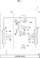
Fig. 1 is a diagram showing an example of a configuration of an air conditioner according to a first embodiment of the present disclosure. -
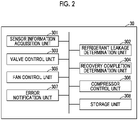
Fig. 2 is a diagram showing an example of a configuration of a control device according to the first embodiment of the present disclosure. -
Fig. 3 is a first diagram for explaining a determination whether recovery of a refrigerant has been completed in the first embodiment of the present disclosure. -
Fig. 4 is a second diagram for explaining a determination whether the recovery of the refrigerant has been completed in the first embodiment of the present disclosure. -
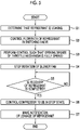
Fig. 5 is a diagram showing an example of a processing flow of the air conditioner according to the first embodiment of the present disclosure. -
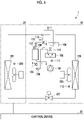
Fig. 6 is a diagram showing an example of a configuration of an air conditioner according to a second embodiment of the present disclosure. -
Fig. 7 is a diagram showing an example of a processing flow of the air conditioner according to the second embodiment of the present disclosure. -
Fig. 8 is a schematic block diagram illustrating a configuration of a computer according to at least one embodiment. - Hereinafter, embodiments will be described in detail with reference to the drawings.
- The configuration of an
air conditioner 1 according to a first embodiment of the present disclosure will be described. - The
air conditioner 1 according to the first embodiment of the present disclosure is an air conditioner that recovers the refrigerant in the receiver, when the leakage of the refrigerant from the air conditioner is detected. As shown inFig. 1 , theair conditioner 1 includes anoutdoor unit 10, anindoor unit 20, and acontrol device 30. - In the first embodiment, the
air conditioner 1 will be described by using the operation during the cooling operation as an example (that is, by using the case of operating as a refrigerating cycle device as an example) among the heating and cooling operations of theair conditioner 1, and the operation during the heating operation will be described at the end of the first embodiment. - As shown in
Fig. 1 , theoutdoor unit 10 includes acompressor 101, anaccumulator 102, a switching valve 103 (an example of a switching valve), a four-way valve 104, ablower fan 105, a heat exchanger 106 (an example of a condenser, an example of a compressor), a throttle mechanism 107 (an example of an expansion valve), acheck valve 108, areceiver 109, an on/offvalve 110, adischarge temperature sensor 111, areceiver temperature sensor 112, and a gas sensor 113 (an example of a gas sensor). - The
compressor 101 is a device that compresses a gaseous refrigerant. The refrigerant compressed by thecompressor 101 is normally sent to theheat exchanger 106 via theswitching valve 103 and the four-way valve 104. - The
accumulator 102 is a device that separates a liquid refrigerant and a gaseous refrigerant. Only the gaseous refrigerant among the refrigerants separated by theaccumulator 102 is sent to thecompressor 101. - The
switching valve 103 is a valve that switches the destination of the refrigerant discharged from thecompressor 101. - For example, the
switching valve 103 normally sets the destination of the refrigerant discharged from thecompressor 101 to theheat exchanger 106. Further, when the leakage of the refrigerant is detected, theswitching valve 103 uses thereceiver 109 as the destination of the refrigerant discharged from thecompressor 101. - The four-
way valve 104 is a valve that switches between a cooling operation and a heating operation of theair conditioner 1. The four-way valve 104 uses theheat exchanger 106 as the destination of the refrigerant discharged from thecompressor 101, during the cooling operation of theair conditioner 1. During the heating operation, the destination of the refrigerant is theheat exchanger 201. - The
blower fan 105 is a fan that sends air to theheat exchanger 106. - The
heat exchanger 106 operates as a condenser during the cooling operation of theair conditioner 1. That is, the gaseous refrigerant exchanges heat with the air sent by theblower fan 105 and becomes a liquid refrigerant. The liquid refrigerant in theheat exchanger 106 is sent to thethrottle mechanism 107. - The
throttle mechanism 107 includes a mechanism for reducing the pressure of the refrigerant and expanding the refrigerant. Thethrottle mechanism 107 reduces the temperature of the refrigerant. Thethrottle mechanism 107 is provided between theheat exchanger 106 and theheat exchanger 201, which will be described later. Thethrottle mechanism 107 is, for example, an electronic expansion valve. - The
check valve 108 is a valve that prevents the backflow of the refrigerant. For example, when leakage of a refrigerant is detected and thereceiver 109 is set as the destination of the refrigerant discharged from thecompressor 101 by theswitching valve 103, thecheck valve 108 sends the refrigerant only in the direction from thecompressor 101 to thereceiver 109. - The
receiver 109 is a container that recovers and stores the refrigerant inside, when the leakage of the refrigerant is detected. - The on/off
valve 110 is a valve that opens and closes the flow path of the refrigerant. For example, the on/offvalve 110 is an electromagnetic valve. - The
discharge temperature sensor 111 is a sensor that measures the temperature in the refrigerant discharge unit of thecompressor 101. Thedischarge temperature sensor 111 is provided in the refrigerant discharge unit of thecompressor 101. - The
receiver temperature sensor 112 is a sensor that measures the temperature at thereceiver 109. Thereceiver temperature sensor 112 is provided above thereceiver 109. - The
gas sensor 113 is a sensor that detects a gaseous refrigerant. For example, thegas sensor 113 is provided in the vicinity of theheat exchanger 106. - As shown in
Fig. 1 , theindoor unit 20 includes a heat exchanger 201 (an example of a compressor and an example of a condenser), ablower fan 202, and a gas sensor 203 (an example of a gas sensor). - The
blower fan 202 is a fan that sends air to theheat exchanger 201. Theheat exchanger 201 operates as an evaporator during the cooling operation of theair conditioner 1. That is, the refrigerant of which temperature is reduced by thethrottle mechanism 107 exchanges heat with the air sent by theblower fan 202 and becomes a gaseous refrigerant. That is, theair conditioner 1 operates as a cooling cycle device. - The
gas sensor 203 is a sensor that detects a gaseous refrigerant. For example, thegas sensor 203 is provided in the vicinity of theheat exchanger 201. - As shown in
Fig. 2 , thecontrol device 30 includes a sensorinformation acquisition unit 301, a refrigerantleakage determination unit 302, a valve control unit 303 (an example of a first control unit and an example of a second control unit), a recovery completion determination unit 304 (an example of a determination unit), afan control unit 305, and astorage unit 308. - The sensor
information acquisition unit 301 acquires the measurement result of the temperature measured by thedischarge temperature sensor 111 or thereceiver temperature sensor 112. Further, the sensorinformation acquisition unit 301 acquires the detection result of the refrigerant from thegas sensor 113 and thegas sensor 203. - The refrigerant
leakage determination unit 302 determines whether or not the refrigerant is leaking in theair conditioner 1, based on the detection result of thegas sensor 113 or thegas sensor 203. - For example, when the
gas sensor 113 detects the refrigerant, the refrigerantleakage determination unit 302 determines that the refrigerant is leaking in theoutdoor unit 10. - Further, for example, when the
gas sensor 203 detects the refrigerant, the refrigerantleakage determination unit 302 determines that the refrigerant is leaking in theindoor unit 20. - The
valve control unit 303 controls the switchingvalve 103, the four-way valve 104, thethrottle mechanism 107, and the on/offvalve 110. - For example, during the normal cooling operation of the
air conditioner 1, thevalve control unit 303 controls the flow path of the refrigerant in the switchingvalve 103 to connect thecompressor 101 and the four-way valve 104, and connect thecheck valve 108 and the on/offvalve 110. Further, thevalve control unit 303 controls the flow path of the refrigerant in the four-way valve 104 to connect the switchingvalve 103 and theheat exchanger 106 and connect theaccumulator 102 and theheat exchanger 201. Further, thevalve control unit 303 performs control such that the opening degree of thethrottle mechanism 107 becomes an appropriate opening degree. Further, thevalve control unit 303 controls the on/offvalve 110 to be shut off. - Further, for example, when the leakage of a refrigerant is detected in the cooling operation of the
air conditioner 1, thevalve control unit 303 controls the flow path of the refrigerant in the switchingvalve 103 to connect thecompressor 101 and thecheck valve 108, and connect the four-way valve 104 and the on/offvalve 110. Further, thevalve control unit 303 controls the flow path of the refrigerant in the four-way valve 104 to connect the switchingvalve 103 and theheat exchanger 106 and connect theaccumulator 102 and theheat exchanger 201. Further, thevalve control unit 303 controls the opening degree of thethrottle mechanism 107 to full open. Further, thevalve control unit 303 controls the on/offvalve 110 to be shut off. - The recovery
completion determination unit 304 determines whether or not the recovery of the refrigerant in thereceiver 109 has been completed, based on the measurement result of thedischarge temperature sensor 111 or the measurement result of thereceiver temperature sensor 112. - For example, when the refrigerant is recovered in the
receiver 109, as shown inFig. 3 , the temperature measured by thereceiver temperature sensor 112 rises, and then the temperature rise slows down. Therefore, the recoverycompletion determination unit 304 determines that the recovery of the refrigerant has been completed, when the measurement result of thereceiver temperature sensor 112 determines that the rise has slowed down after the rise. - Further, for example, when the refrigerant is recovered in the
receiver 109, the temperature measured by thedischarge temperature sensor 111 decreases as shown inFig. 4 . The measurement result of thedischarge temperature sensor 111 reaches the lower limit of the temperature when the refrigerant runs out, and then the temperature rises due to the heat of the motor of thecompressor 101. Therefore, when it is determined that the measurement result of thedischarge temperature sensor 111 decreases to the lower limit of the temperature and then increases, the recoverycompletion determination unit 304 determines that the recovery of the refrigerant has been completed. - The
fan control unit 305 controls the rotation of theblower fan 105 and theblower fan 202. - The
compressor control unit 306 controls the operation of thecompressor 101. - For example, the
compressor control unit 306 controls thecompressor 101 to be in an operating state or a stopped state. - The
error notification unit 307 makes a notification of the leakage of the refrigerant. - For example, the
error notification unit 307 displays the leakage of the refrigerant on a display unit provided in the room or a display unit of the remote controller. - The
storage unit 308 stores various types of information necessary for the process performed by thecontrol device 30. - For example, the
storage unit 308 stores the temperature threshold value used by the recoverycompletion determination unit 304 to determine whether or not the recovery of the refrigerant in thereceiver 109 has been completed. - With the above-described configuration, during the normal cooling operation of the
air conditioner 1, the refrigerant flows through a flow path that circulates in the order of thecompressor 101, the switchingvalve 103, the four-way valve 104, theheat exchanger 106, thethrottle mechanism 107, theheat exchanger 201, the four-way valve 104, theaccumulator 102, and thecompressor 101. - Next, the process of the
air conditioner 1 according to the first embodiment of the present disclosure will be described. - Here, the processing flow of the
air conditioner 1 when the leakage of the refrigerant is detected in theheat exchanger 106 that operates as a condenser during the normal cooling operation of theair conditioner 1 shown inFig. 5 will be described. - The
air conditioner 1 is in a state of the normal cooling operation. That is, thevalve control unit 303 controls the flow path of the refrigerant in the switchingvalve 103 to connect thecompressor 101 and the four-way valve 104, and connect thecheck valve 108 and the on/offvalve 110. Further, thevalve control unit 303 controls the flow path of the refrigerant in the four-way valve 104 to connect the on/offvalve 110 and theheat exchanger 106 and connect theaccumulator 102 and theheat exchanger 201. Further, thevalve control unit 303 performs control such that the opening degree of thethrottle mechanism 107 becomes an appropriate opening degree. Further, thevalve control unit 303 controls the on/offvalve 110 to be shut off. - In this state, the refrigerant
leakage determination unit 302 determines whether or not the refrigerant is leaking in theair conditioner 1, based on the detection result of thegas sensor 113 or thegas sensor 203. - Specifically, the refrigerant
leakage determination unit 302 determines that the refrigerant is leaking when thegas sensor 113 or thegas sensor 203 detects the refrigerant. - Here, the
gas sensor 113 detects the refrigerant. - The sensor
information acquisition unit 301 acquires a detection result indicating that the refrigerant has been detected from thegas sensor 113. - When acquiring a detection result indicating that the sensor
information acquisition unit 301 has detected the refrigerant from thegas sensor 113, the refrigerantleakage determination unit 302 determines that the refrigerant is leaking in the outdoor unit 10 (step S1). - The
valve control unit 303 controls the flow path of the refrigerant in the switchingvalve 103 to connect thecompressor 101 and thecheck valve 108, and connect the four-way valve 104 and the on/off valve 110 (step S2). - The
valve control unit 303 controls the opening degree of thethrottle mechanism 107 to full open (step S3). Thefan control unit 305 stops the rotation of the blower fan 202 (step S4). In addition, the process of step S3 and step S4 reduces the gasification of the refrigerant, so that the density of the refrigerant is increased. As a result, the refrigerant can be efficiently recovered in thereceiver 109. - The recovery
completion determination unit 304 determines whether or not the recovery of the refrigerant in thereceiver 109 has been completed, based on the measurement result of thedischarge temperature sensor 111 or the measurement result of the receiver temperature sensor 112 (step S5). - When the recovery
completion determination unit 304 determines that the recovery of the refrigerant in thereceiver 109 has not been completed (NO in step S5), the process returns to the process of step S5. - Further, when the recovery
completion determination unit 304 determines that the recovery of the refrigerant in thereceiver 109 has been completed (YES in step S5), thecompressor control unit 306 controls thecompressor 101 to stop (from the operating state) (step S6). Then, theerror notification unit 307 notifies the leakage of the refrigerant (step S7). - In this way, when the refrigerant leaks in the
heat exchanger 106 that operates as a condenser, theair conditioner 1 can reduce the leakage of the refrigerant from theheat exchanger 106. In this case, theair conditioner 1 can recover the refrigerant on the inlet side of theheat exchanger 106. Therefore, theair conditioner 1 can recover the refrigerant more safely than the case where the refrigerant is recovered on the outlet side of theheat exchanger 106. - Further, in the cooling operation of the
air conditioner 1, even when the refrigerant leaks from theheat exchanger 201 operating as an evaporator, and other places, and thegas sensor 113 or thegas sensor 203 detects the refrigerant, similarly, thereceiver 109 may recover the refrigerant. - Further, in the heating operation of the
air conditioner 1, theheat exchanger 106 operates as an evaporator, theheat exchanger 201 operates as a condenser, and thevalve control unit 303 controls the flow path of the refrigerant in the four-way valve 104 to connect the switchingvalve 103 and theheat exchanger 201 and connect theaccumulator 102 and theheat exchanger 106. The rotation of theblower fan 105 is stopped in step S4. - Then, in the heating operation of the
air conditioner 1, even when the refrigerant leaks from theheat exchanger 201 operating as a condenser, theheat exchanger 106 operating as an evaporator, and other places, and thegas sensor 113 or thegas sensor 203 detects the refrigerant, similarly, thereceiver 109 may recover the refrigerant. - When the refrigerant leaks in the
heat exchanger 201 during the heating operation of theair conditioner 1, theair conditioner 1 can recover the refrigerant on the inlet side of theheat exchanger 201. Therefore, theair conditioner 1 can recover the refrigerant more safely than the case where the refrigerant is recovered on the outlet side of theheat exchanger 201. - The
air conditioner 1 according to the first embodiment of the present disclosure has been described above. - The air conditioner (1) according to the first embodiment of the present disclosure includes a condenser (106, 201) that condenses a refrigerant, an evaporator (201, 106) that evaporates the condensed refrigerant, a compressor (101) that compresses the evaporated refrigerant, a receiver (109) capable of recovering the compressed refrigerant, and a switching valve (103) capable of switching a discharge destination of the compressed refrigerant from the condenser (106, 201) to the receiver (109).
- By the air conditioner (1), when the leakage of the refrigerant is detected, the refrigerant can be recovered on the inlet side of the condenser (106, 201). As a result, the air conditioner (1) can reduce the leakage, when the refrigerant leaks in the air conditioner.
- The configuration of the
air conditioner 1 according to the second embodiment of the present disclosure will be described. - The
air conditioner 1 according to the second embodiment of the present disclosure is an air conditioner that uses a receiver as a substitute for an accumulator as well as for the recovery of a refrigerant. As shown inFig. 6 , theair conditioner 1 includes theoutdoor unit 10, theindoor unit 20, and thecontrol device 30. Hereinafter, theair conditioner 1 will be described with a focus on the differences from the first embodiment. - In the second embodiment, the
air conditioner 1 will be described by using the operation during the cooling operation as an example (that is, by using the case of operating as a refrigerating cycle device as an example) among the heating and cooling operations of theair conditioner 1, and the operation during the heating operation will be described at the end of the second embodiment. - As shown in
Fig. 6 , theoutdoor unit 10 includes thecompressor 101, the switchingvalve 103, the four-way valve 104, theblower fan 105, theheat exchanger 106, thethrottle mechanism 107, thecheck valve 108, thereceiver 109, a first on/offvalve 110, adischarge temperature sensor 111, areceiver temperature sensor 112, agas sensor 113, a second on/offvalve 114, a first three-way valve 115 (an example of a switching valve), and a second three-way valve 116 (an example of a switching valve). - The first three-
way valve 115 and the second three-way valve 116 are valves added to operate thereceiver 109 as an accumulator in addition to recovering the refrigerant. - The
valve control unit 303 controls the switchingvalve 103, the four-way valve 104, thethrottle mechanism 107, the first on/offvalve 110, the second on/offvalve 114, the first three-way valve 115, and the second three-way valve 116. - For example, during the normal cooling operation of the
air conditioner 1, thevalve control unit 303 controls the flow path of the refrigerant in the switchingvalve 103 to connect thecompressor 101 and the four-way valve 104, and connect thecheck valve 108 and the second on/offvalve 114. Further, thevalve control unit 303 controls the flow path of the refrigerant in the four-way valve 104 to connect the switchingvalve 103 and theheat exchanger 106 and connect the first three-way valve 115 and theheat exchanger 201. Further, thevalve control unit 303 controls the opening degree of thethrottle mechanism 107 to an appropriate opening degree. Further, thevalve control unit 303 controls the first on/offvalve 110 to open. Further, thevalve control unit 303 controls the second on/offvalve 114 to be shut off. Further, thevalve control unit 303 controls the first three-way valve 115 to connect the four-way valve 104 and the first on/offvalve 110. Further, thevalve control unit 303 controls the second three-way valve 116 to connect thecompressor 101 and thereceiver 109. - Further, for example, when the leakage of a refrigerant is detected in the cooling operation of the
air conditioner 1, thevalve control unit 303 controls the flow path of the refrigerant in the switchingvalve 103 to connect thecompressor 101 and thecheck valve 108, and connect the four-way valve 104 and the second on/offvalve 114. Further, thevalve control unit 303 controls the flow path of the refrigerant in the four-way valve 104 to connect the switchingvalve 103 and theheat exchanger 106 and connect the first three-way valve 115 and theheat exchanger 201. Further, thevalve control unit 303 controls the opening degree of thethrottle mechanism 107 to full open. Further, thevalve control unit 303 controls the first on/offvalve 110 to be shut off. Further, thevalve control unit 303 controls the second on/offvalve 114 to be shut off. Further, thevalve control unit 303 controls the first three-way valve 115 to connect thecompressor 101 and the four-way valve 104. Further, thevalve control unit 303 controls the second three-way valve 116 to connect thecheck valve 108 and thereceiver 109. - With the above-described configuration, during the normal cooling operation of the
air conditioner 1, the refrigerant flows through a flow path that circulates in the order of thecompressor 101, the switchingvalve 103, the four-way valve 104, theheat exchanger 106, thethrottle mechanism 107, theheat exchanger 201, the four-way valve 104, the first three-way valve 115, the first on/offvalve 110, thereceiver 109, the second three-way valve 116, and thecompressor 101. - In
Fig. 6 , the arrow indicated by the solid line indicates the flow of the refrigerant during the normal cooling operation of theair conditioner 1. Further, the arrow shown by the broken line indicates the flow of the refrigerant when the leakage of the refrigerant is detected in the cooling operation of theair conditioner 1. - Next, the process of the
air conditioner 1 according to the second embodiment of the present disclosure will be described. - Here, the processing flow of the
air conditioner 1 when the leakage of the refrigerant is detected in theheat exchanger 106 that operates as a condenser during the normal cooling operation of theair conditioner 1 shown inFig. 7 will be described. - The
air conditioner 1 is in a state of the normal cooling operation. That is, thevalve control unit 303 controls the flow path of the refrigerant in the switchingvalve 103 to connect thecompressor 101 and the four-way valve 104, and connect thecheck valve 108 and the second on/offvalve 114. Further, thevalve control unit 303 controls the flow path of the refrigerant in the four-way valve 104 to connect the switchingvalve 103 and theheat exchanger 106 and connect the first three-way valve 115 and theheat exchanger 201. Further, thevalve control unit 303 performs control such that the opening degree of thethrottle mechanism 107 becomes an appropriate opening degree. Further, thevalve control unit 303 controls the first on/offvalve 110 to open. Further, thevalve control unit 303 controls the second on/offvalve 114 to be shut off. Further, thevalve control unit 303 controls the first three-way valve 115 to connect the four-way valve 104 and the first on/offvalve 110. Further, thevalve control unit 303 controls the second three-way valve 116 to connect thecompressor 101 and thereceiver 109. - In this state, the refrigerant
leakage determination unit 302 determines whether or not the refrigerant is leaking in theair conditioner 1, based on the detection result of thegas sensor 113 or thegas sensor 203. - Specifically, the refrigerant
leakage determination unit 302 determines that the refrigerant is leaking when thegas sensor 113 or thegas sensor 203 detects the refrigerant. - Here, the
gas sensor 113 detects the gaseous refrigerant. - The sensor
information acquisition unit 301 acquires a detection result indicating that the refrigerant has been detected from thegas sensor 113. - When acquiring a detection result indicating that the sensor
information acquisition unit 301 has detected the refrigerant from thegas sensor 113, the refrigerantleakage determination unit 302 determines that the refrigerant is leaking in the outdoor unit 10 (step S1). - The
valve control unit 303 controls the flow path of the refrigerant in the switchingvalve 103 to connect thecompressor 101 and thecheck valve 108, and connect the four-way valve 104 and the second on/offvalve 114, controls the first on/offvalve 110 to be shut off, controls the first three-way valve 115 to connect thecompressor 101 and the four-way valve 104, and controls the second three-way valve 116 to connect thecheck valve 108 and the receiver 109 (step S11). - The
valve control unit 303 controls the opening degree of thethrottle mechanism 107 to full open (step S3). Thefan control unit 305 stops the rotation of the blower fan 202 (step S4). - The recovery
completion determination unit 304 determines whether or not the recovery of the refrigerant in thereceiver 109 has been completed, based on the measurement result of thedischarge temperature sensor 111 or the measurement result of the receiver temperature sensor 112 (step S5). - When the recovery
completion determination unit 304 determines that the recovery of the refrigerant in thereceiver 109 has not been completed (NO in step S5), the process returns to the process of step S5. - Further, when the recovery
completion determination unit 304 determines that the recovery of the refrigerant in thereceiver 109 has been completed (YES in step S5), thecompressor control unit 306 controls thecompressor 101 to stop (from the operating state) (step S6). Then, theerror notification unit 307 notifies the leakage of the refrigerant (step S7). - In this way, when the refrigerant leaks in the
heat exchanger 106 that operates as a condenser, theair conditioner 1 can reduce the leakage of the refrigerant from theheat exchanger 106. In this case, theair conditioner 1 can recover the refrigerant on the inlet side of theheat exchanger 106. Therefore, theair conditioner 1 can recover the refrigerant more safely than the case where the refrigerant is recovered on the outlet side of theheat exchanger 106. - Further, in the cooling operation of the
air conditioner 1, even when the refrigerant leaks from theheat exchanger 201 operating as an evaporator, and other places, and thegas sensor 113 or thegas sensor 203 detects the refrigerant, similarly, thereceiver 109 may recover the refrigerant. - Further, in the heating operation of the
air conditioner 1, theheat exchanger 106 operates as an evaporator, theheat exchanger 201 operates as a condenser, and thevalve control unit 303 controls the flow path of the refrigerant in the four-way valve 104 to connect the switchingvalve 103 and theheat exchanger 201 and connect theaccumulator 102 and theheat exchanger 106. The rotation of theblower fan 105 is stopped in step S4. - Then, in the heating operation of the
air conditioner 1, even when the refrigerant leaks from theheat exchanger 201 operating as a condenser, theheat exchanger 106 operating as an evaporator, and other places, and thegas sensor 113 or thegas sensor 203 detects the refrigerant, similarly, thereceiver 109 may recover the refrigerant. - When the refrigerant leaks in the
heat exchanger 201 during the heating operation of theair conditioner 1, theair conditioner 1 can recover the refrigerant on the inlet side of theheat exchanger 201. Therefore, theair conditioner 1 can recover the refrigerant more safely than the case where the refrigerant is recovered on the outlet side of theheat exchanger 201. - The
air conditioner 1 according to the second embodiment of the present disclosure has been described above. - The air conditioner (1) according to the second embodiment of the present disclosure includes a receiver (109) that operates as an accumulator that separates a liquid refrigerant and a gaseous refrigerant.
- This air conditioner (1) eliminates the need for an accumulator, and the
air conditioner 1 can be manufactured easily and inexpensively. - In another embodiment of the present disclosure, the
control device 30 may be provided in theoutdoor unit 10 or theindoor unit 20. - In the process according to the embodiment of the present disclosure, the order of processing may be changed as long as appropriate processing is performed.
- Each of the
storage unit 308 and the storage device (including a register and a latch) in the embodiment of the present disclosure may be provided anywhere within a range in which appropriate information is transmitted and received. Further, a plurality of thestorage units 308 and the storage devices may be present in places within a range in which appropriate information is transmitted and received, and may distribute and store data. - Although the embodiment of the present disclosure has been described, the above-described
control device 30 and other control devices may have a computer system inside. Then, the procedures of the processes described above are stored in a computer-readable recording medium in the form of a program, and the above processes are performed by the program being read and executed by the computer. A specific example of a computer is shown below. -
Fig. 8 is a schematic block diagram illustrating a configuration of a computer according to at least one embodiment. - As shown in
Fig. 8 , acomputer 5 includes aCPU 6, amain memory 7, astorage 8, and aninterface 9. - For example, each of the above-described
control device 30 and other control devices is mounted on thecomputer 5. The operation of each processing unit described above is stored in thestorage 8 in the form of a program. TheCPU 6 reads a program from thestorage 8, expands the read program into themain memory 7, and executes the above process according to the program. Further,CPU 6 secures a storage area corresponding to each of the above-described storage units in themain memory 7, according to the program. - Examples of the
storage 8 include a Hard Disk Drive (HDD), a Solid State Drive (SSD), a magnetic disk, an optical magnetic disk, a Compact Disc Read Only Memory (CD-ROM), a Digital Versatile Disc Read Only Memory (DVD-ROM), a semiconductor memory, and the like. Thestorage 8 may be an internal medium directly connected to the bus of thecomputer 5, or may be an external medium connected to thecomputer 5 through theinterface 9 or a communication line. Further, when this program is delivered to thecomputer 5 through a communication line, thecomputer 5 receiving the delivered program may develop the program in themain memory 7 and execute the above process. In at least one embodiment, thestorage 8 is a non-transitory tangible storage medium. - Further, the above program may implement a part of the above-described functions. Further, the program may be a so-called difference file (difference program), which can implement the above-described functions in combination with a program already recorded in the computer system.
- Although some embodiments of the present disclosure have been described, these embodiments are examples and do not limit the scope of the disclosure. These embodiments may be subject to various additions, various omissions, various replacements, and various changes without departing from the gist of the disclosure.
- The air conditioner (1), the control method, and the program described in each embodiment of the present disclosure are understood as follows, for example.
-
- (1) An air conditioner (1) according to a first aspect includes a condenser (106, 201) that condenses a refrigerant, an evaporator (201, 106) that evaporates the condensed refrigerant, a compressor (101) that compresses the evaporated refrigerant, a receiver (109) capable of recovering the compressed refrigerant, and a switching valve (103, 115, 116) capable of switching a discharge destination of the compressed refrigerant from the condenser (106, 201) to the receiver (109).
- By the air conditioner (1), when the leakage of the refrigerant is detected, the refrigerant can be recovered on the inlet side of the condenser (106, 201). As a result, the air conditioner (1) can reduce the leakage, when the refrigerant leaks in the air conditioner.
- (2) The air conditioner (1) according to a second aspect is the air conditioner (1) according to (1) and may further include a gas sensors (113, 203) that detects leakage of the refrigerant, in which the switching valve (103, 115, 116) may switch the discharge destination from the condenser (106, 201) to the receiver (109), when the gas sensor (113, 203) detects the leakage.
- The air conditioner (1) makes it possible to detect the leakage of the refrigerant and appropriately switch the discharge destination.
- (3) The air conditioner (1) according to a third aspect is the air conditioner (1) according to (1) or (2), in which the receiver (109) may operate as an accumulator that separates a liquid refrigerant and a gaseous refrigerant.
- This air conditioner (1) eliminates the need for an accumulator, and the
air conditioner 1 can be manufactured easily and inexpensively. - (4) The air conditioner (1) according to a fourth aspect is the air conditioner (1) according to any one of (1) to (3) and may further include a first control unit (303) that controls a flow path in the switching valve (103, 115, 116).
- The air conditioner (1) makes it possible to appropriately control the flow path in the switching valve (103, 115, 116).
- (5) The air conditioner (1) according to a fifth aspect is the air conditioner (1) according to any one of (1) to (4) and may further include an expansion valve (107) provided between the evaporator (201, 106) and the condenser (106, 201) and capable of controlling a valve opening degree to full open, when the discharge destination is switched from the condenser (106, 201) to the receiver.
- With this air conditioner (1), the temperature of the refrigerant is reduced and the density of the refrigerant is increased. As a result, the refrigerant can be safely recovered to the receiver (109).
- (6) The air conditioner (1) according to a sixth aspect is the air conditioner (1) according to (5) and may further include a second control unit (303) that controls the valve opening degree.
- The air conditioner (1) makes it possible to appropriately control the valve opening degree.
- (7) The air conditioner (1) according to a seventh aspect is the air conditioner (1) according to any one of (1) to (6), and may further include a determination unit (304) that determines whether or not recovery of the refrigerant by the receiver (109) has been completed.
- The air conditioner (1) makes it possible to determine the completion of the recovery of the refrigerant. As a result, it is not necessary to perform unnecessary control after the recovery of the refrigerant has been completed.
- (8) The air conditioner (1) according to an eighth aspect is the air conditioner (1) according to (7), in which the determination unit (304) may determine whether or not the recovery has been completed, based on a temperature at a discharge unit of the compressor (101) or a temperature at the receiver (109).
- The air conditioner (1) makes it possible to determine the completion of the recovery of the refrigerant by using an easy method. As a result, it is not necessary to perform unnecessary control after the recovery of the refrigerant has been completed.
- (9) A control method according to a ninth aspect performed by an air conditioner (1) including a condenser (106, 201) that condenses a refrigerant, an evaporator (201, 106) that evaporates the condensed refrigerant, a compressor (101) that compresses the evaporated refrigerant, a receiver (109) capable of recovering the compressed refrigerant, and a switching valve (103, 115, 116) capable of switching a discharge destination of the compressed refrigerant from the condenser (106, 201) to the receiver (109), the method including: controlling a flow path in the switching valve (103, 115, 116).
- According to this control method, it is possible to recover the refrigerant on the inlet side of the condenser (106, 201), when the leakage of the refrigerant is detected. As a result, the control method can reduce the leakage, when the refrigerant leaks in the air conditioner.
- (10) A program according to a tenth aspect causes a computer (5) in an air conditioner to control a flow path in a switching valve (103, 115, 116), the air conditioner (1) including a condenser (106, 201) that condenses a refrigerant, an evaporator (201, 106) that evaporates the condensed refrigerant, a compressor (101) that compresses the evaporated refrigerant, a receiver (109) capable of recovering the compressed refrigerant, and the switching valve (103, 115, 116) capable of switching a discharge destination of the compressed refrigerant from the condenser (106, 201) to the receiver (109).
- According to this program, it is possible to recover the refrigerant on the inlet side of the condenser (106, 201), when the leakage of the refrigerant is detected. As a result, the program can reduce the leakage, when the refrigerant leaks in the air conditioner.
- According to the air conditioner, the control method, and the program according to the embodiment of the present disclosure, when the refrigerant leaks in the air conditioner, the leakage can be reduced.
-
- 1
- Air conditioner
- 5
- Computer
- 6
- CPU
- 7
- Main memory
- 8
- Storage
- 9
- Interface
- 10
- Outdoor unit
- 20
- Indoor unit
- 30
- Control device
- 101
- Compressor
- 102
- Accumulator
- 103
- Switching valve
- 104
- Four-way valve
- 105, 202
- Blower fan
- 106, 201
- Heat exchanger
- 107
- Throttle mechanism
- 108
- Check valve
- 109
- Receiver
- 110, 114
- On/off valve
- 111
- Discharge temperature sensor
- 112
- Receiver temperature sensor
- 113, 203
- Gas sensor
- 301
- Sensor information acquisition unit
- 302
- Refrigerant leakage determination unit
- 303
- Valve control unit
- 304
- Recovery completion determination unit
- 305
- Fan control unit
- 306
- Compressor control unit
- 307
- Error notification unit
- 308
- Storage unit
Claims (10)
- An air conditioner comprising:a condenser that condenses a refrigerant;an evaporator that evaporates the condensed refrigerant;a compressor that compresses the evaporated refrigerant;a receiver capable of recovering the compressed refrigerant; anda switching valve capable of switching a discharge destination of the compressed refrigerant from the condenser to the receiver.
- The air conditioner according to claim 1, further comprising:a gas sensor that detects leakage of the refrigerant, whereinthe switching valve switches the discharge destination from the condenser to the receiver, when the gas sensor has detected the leakage.
- The air conditioner according to claim 1 or 2, wherein
the receiver operates as an accumulator that separates a liquid refrigerant and a gaseous refrigerant. - The air conditioner according to any one of claims 1 to 3, further comprising:
a first control unit that controls a flow path in the switching valve. - The air conditioner according to any one of claims 1 to 4, further comprising:
an expansion valve provided between the evaporator and the condenser and capable of controlling a valve opening degree to full open, when the discharge destination is switched from the condenser to the receiver. - The air conditioner according to claim 5, further comprising:
a second control unit that controls the valve opening degree of the expansion valve. - The air conditioner according to any one of claims 1 to 6, further comprising:
a determination unit that determines whether or not recovery of the refrigerant by the receiver has been completed. - The air conditioner according to claim 7, wherein
the determination unit determines whether or not the recovery has been completed, based on a temperature at a discharge unit of the compressor or a temperature at the receiver. - A control method performed by an air conditioner including a condenser that condenses a refrigerant, an evaporator that evaporates the condensed refrigerant, a compressor that compresses the evaporated refrigerant, a receiver capable of recovering the compressed refrigerant, and a switching valve capable of switching a discharge destination of the compressed refrigerant from the condenser to the receiver, the method comprising:
controlling a flow path in the switching valve. - A program causing a computer in an air conditioner to control a flow path in a switching valve, the air conditioner including a condenser that condenses a refrigerant, an evaporator that evaporates the condensed refrigerant, a compressor that compresses the evaporated refrigerant, a receiver capable of recovering the compressed refrigerant, and the switching valve capable of switching a discharge destination of the compressed refrigerant from the condenser to the receiver.
Applications Claiming Priority (2)
| Application Number | Priority Date | Filing Date | Title |
|---|---|---|---|
| JP2020066032A JP7557952B2 (en) | 2020-04-01 | 2020-04-01 | Air conditioner, processing method and program |
| PCT/JP2021/014205 WO2021201242A1 (en) | 2020-04-01 | 2021-04-01 | Air conditioner, control method, and program |
Publications (2)
| Publication Number | Publication Date |
|---|---|
| EP4113038A1 true EP4113038A1 (en) | 2023-01-04 |
| EP4113038A4 EP4113038A4 (en) | 2023-08-02 |
Family
ID=77927322
Family Applications (1)
| Application Number | Title | Priority Date | Filing Date |
|---|---|---|---|
| EP21780480.6A Pending EP4113038A4 (en) | 2020-04-01 | 2021-04-01 | AIR CONDITIONING, CONTROL METHOD AND PROGRAM |
Country Status (3)
| Country | Link |
|---|---|
| EP (1) | EP4113038A4 (en) |
| JP (1) | JP7557952B2 (en) |
| WO (1) | WO2021201242A1 (en) |
Cited By (2)
| Publication number | Priority date | Publication date | Assignee | Title |
|---|---|---|---|---|
| US12000631B1 (en) * | 2022-12-13 | 2024-06-04 | Lennox Industries Inc. | Systems and methods for refrigerant leak mitigation |
| EP4686899A1 (en) * | 2024-08-02 | 2026-02-04 | BDR Thermea Group B.V. | Controller, method, computer program product and non transitory computer readable medium for monitoring leakage of refrigerant, heat pump comprsing the controller |
Families Citing this family (1)
| Publication number | Priority date | Publication date | Assignee | Title |
|---|---|---|---|---|
| JP2026038370A (en) * | 2024-08-23 | 2026-03-06 | ダイキン工業株式会社 | Refrigeration equipment |
Family Cites Families (13)
| Publication number | Priority date | Publication date | Assignee | Title |
|---|---|---|---|---|
| JP2000028237A (en) * | 1998-07-14 | 2000-01-28 | Matsushita Electric Ind Co Ltd | Separate refrigeration cycle device |
| JP4599699B2 (en) * | 2000-09-26 | 2010-12-15 | ダイキン工業株式会社 | Air conditioner |
| JP2012127519A (en) * | 2010-12-13 | 2012-07-05 | Panasonic Corp | Air conditioner |
| JP6361258B2 (en) * | 2014-04-18 | 2018-07-25 | ダイキン工業株式会社 | Refrigeration equipment |
| CN103940158B (en) * | 2014-04-22 | 2017-01-11 | 珠海格力电器股份有限公司 | Air conditioner outdoor unit, air conditioner system and operation method of air conditioner system |
| JP6361263B2 (en) * | 2014-04-23 | 2018-07-25 | ダイキン工業株式会社 | Air conditioner |
| JP6372307B2 (en) * | 2014-10-27 | 2018-08-15 | ダイキン工業株式会社 | Heat pump equipment |
| WO2017163321A1 (en) * | 2016-03-23 | 2017-09-28 | 三菱電機株式会社 | Refrigeration cycle device |
| JPWO2017175299A1 (en) | 2016-04-05 | 2018-10-25 | 三菱電機株式会社 | Refrigeration cycle equipment |
| EP3598037B1 (en) * | 2017-03-13 | 2024-02-21 | Mitsubishi Electric Corporation | Refrigeration cycle device |
| JP7005172B2 (en) * | 2017-05-26 | 2022-01-21 | 日立ジョンソンコントロールズ空調株式会社 | Air conditioner |
| WO2019053771A1 (en) * | 2017-09-12 | 2019-03-21 | 三菱電機株式会社 | Air conditioning device |
| JP7146570B2 (en) | 2018-10-25 | 2022-10-04 | オークマ株式会社 | Mounting structure of laser light detection sensor to protective window in machine tool |
-
2020
- 2020-04-01 JP JP2020066032A patent/JP7557952B2/en active Active
-
2021
- 2021-04-01 EP EP21780480.6A patent/EP4113038A4/en active Pending
- 2021-04-01 WO PCT/JP2021/014205 patent/WO2021201242A1/en not_active Ceased
Cited By (3)
| Publication number | Priority date | Publication date | Assignee | Title |
|---|---|---|---|---|
| US12000631B1 (en) * | 2022-12-13 | 2024-06-04 | Lennox Industries Inc. | Systems and methods for refrigerant leak mitigation |
| US20240191920A1 (en) * | 2022-12-13 | 2024-06-13 | Lennox Industries Inc. | Systems and methods for refrigerant leak mitigation |
| EP4686899A1 (en) * | 2024-08-02 | 2026-02-04 | BDR Thermea Group B.V. | Controller, method, computer program product and non transitory computer readable medium for monitoring leakage of refrigerant, heat pump comprsing the controller |
Also Published As
| Publication number | Publication date |
|---|---|
| JP7557952B2 (en) | 2024-09-30 |
| EP4113038A4 (en) | 2023-08-02 |
| JP2021162263A (en) | 2021-10-11 |
| WO2021201242A1 (en) | 2021-10-07 |
Similar Documents
| Publication | Publication Date | Title |
|---|---|---|
| EP3683524B1 (en) | Refrigeration apparatus | |
| CN107709902B (en) | Air conditioning system | |
| EP3486584B1 (en) | Refrigeration system | |
| CN102575884B (en) | Air conditioner | |
| EP3136010B1 (en) | Air-conditioning device | |
| CN204730502U (en) | A kind of cryogenic refrigeration machine room air-conditioner | |
| JPWO2019053858A1 (en) | Refrigeration cycle device and refrigeration device | |
| CN104583684B (en) | Air conditioner | |
| US20220186987A1 (en) | Heat source-side unit and refrigeration apparatus | |
| JP2019143877A (en) | Air conditioning system | |
| JP7557952B2 (en) | Air conditioner, processing method and program | |
| EP3130868A1 (en) | Heat pump system | |
| CN108954501B (en) | Air conditioner | |
| EP4317836A1 (en) | Air conditioner | |
| JP2022179215A (en) | Refrigerant leakage management system | |
| US10006725B2 (en) | Heat source system and method for controlling number of machines to be started at time of power recovery in heat source system | |
| EP3872423B1 (en) | Air conditioning apparatus | |
| CN117396713B (en) | Refrigerant leak detection system | |
| EP4553417A1 (en) | Refrigeration cycle device | |
| EP4343236A1 (en) | Refrigeration cycle device and refrigerant leakage determination system | |
| JP7630648B2 (en) | Refrigeration Cycle Equipment | |
| KR102532274B1 (en) | Air conditioner and control method | |
| JPWO2017098577A1 (en) | Compressor deterioration diagnosis device and compressor deterioration diagnosis method | |
| WO2021117231A1 (en) | Air-conditioner |
Legal Events
| Date | Code | Title | Description |
|---|---|---|---|
| STAA | Information on the status of an ep patent application or granted ep patent |
Free format text: STATUS: THE INTERNATIONAL PUBLICATION HAS BEEN MADE |
|
| PUAI | Public reference made under article 153(3) epc to a published international application that has entered the european phase |
Free format text: ORIGINAL CODE: 0009012 |
|
| STAA | Information on the status of an ep patent application or granted ep patent |
Free format text: STATUS: REQUEST FOR EXAMINATION WAS MADE |
|
| 17P | Request for examination filed |
Effective date: 20220927 |
|
| AK | Designated contracting states |
Kind code of ref document: A1 Designated state(s): AL AT BE BG CH CY CZ DE DK EE ES FI FR GB GR HR HU IE IS IT LI LT LU LV MC MK MT NL NO PL PT RO RS SE SI SK SM TR |
|
| DAV | Request for validation of the european patent (deleted) | ||
| DAX | Request for extension of the european patent (deleted) | ||
| A4 | Supplementary search report drawn up and despatched |
Effective date: 20230703 |
|
| RIC1 | Information provided on ipc code assigned before grant |
Ipc: F25B 1/00 20060101ALI20230627BHEP Ipc: F25B 49/02 20060101ALI20230627BHEP Ipc: F25B 43/00 20060101AFI20230627BHEP |
|
| STAA | Information on the status of an ep patent application or granted ep patent |
Free format text: STATUS: EXAMINATION IS IN PROGRESS |
|
| 17Q | First examination report despatched |
Effective date: 20240321 |
|
| GRAP | Despatch of communication of intention to grant a patent |
Free format text: ORIGINAL CODE: EPIDOSNIGR1 |
|
| STAA | Information on the status of an ep patent application or granted ep patent |
Free format text: STATUS: GRANT OF PATENT IS INTENDED |