EP4113020A1 - Refrigeration cycle device - Google Patents
Refrigeration cycle device Download PDFInfo
- Publication number
- EP4113020A1 EP4113020A1 EP21780800.5A EP21780800A EP4113020A1 EP 4113020 A1 EP4113020 A1 EP 4113020A1 EP 21780800 A EP21780800 A EP 21780800A EP 4113020 A1 EP4113020 A1 EP 4113020A1
- Authority
- EP
- European Patent Office
- Prior art keywords
- compressor
- intermediate plate
- refrigerant
- refrigeration cycle
- refrigerant circuit
- Prior art date
- Legal status (The legal status is an assumption and is not a legal conclusion. Google has not performed a legal analysis and makes no representation as to the accuracy of the status listed.)
- Granted
Links
Images
Classifications
-
- F—MECHANICAL ENGINEERING; LIGHTING; HEATING; WEAPONS; BLASTING
- F24—HEATING; RANGES; VENTILATING
- F24F—AIR-CONDITIONING; AIR-HUMIDIFICATION; VENTILATION; USE OF AIR CURRENTS FOR SCREENING
- F24F1/00—Room units for air-conditioning, e.g. separate or self-contained units or units receiving primary air from a central station
- F24F1/06—Separate outdoor units, e.g. outdoor unit to be linked to a separate room comprising a compressor and a heat exchanger
- F24F1/08—Compressors specially adapted for separate outdoor units
- F24F1/12—Vibration or noise prevention thereof
-
- F—MECHANICAL ENGINEERING; LIGHTING; HEATING; WEAPONS; BLASTING
- F25—REFRIGERATION OR COOLING; COMBINED HEATING AND REFRIGERATION SYSTEMS; HEAT PUMP SYSTEMS; MANUFACTURE OR STORAGE OF ICE; LIQUEFACTION SOLIDIFICATION OF GASES
- F25B—REFRIGERATION MACHINES, PLANTS OR SYSTEMS; COMBINED HEATING AND REFRIGERATION SYSTEMS; HEAT PUMP SYSTEMS
- F25B7/00—Compression machines, plants or systems, with cascade operation, i.e. with two or more circuits, the heat from the condenser of one circuit being absorbed by the evaporator of the next circuit
-
- F—MECHANICAL ENGINEERING; LIGHTING; HEATING; WEAPONS; BLASTING
- F24—HEATING; RANGES; VENTILATING
- F24F—AIR-CONDITIONING; AIR-HUMIDIFICATION; VENTILATION; USE OF AIR CURRENTS FOR SCREENING
- F24F1/00—Room units for air-conditioning, e.g. separate or self-contained units or units receiving primary air from a central station
- F24F1/06—Separate outdoor units, e.g. outdoor unit to be linked to a separate room comprising a compressor and a heat exchanger
- F24F1/26—Refrigerant piping
- F24F1/30—Refrigerant piping for use inside the separate outdoor units
-
- F—MECHANICAL ENGINEERING; LIGHTING; HEATING; WEAPONS; BLASTING
- F24—HEATING; RANGES; VENTILATING
- F24F—AIR-CONDITIONING; AIR-HUMIDIFICATION; VENTILATION; USE OF AIR CURRENTS FOR SCREENING
- F24F13/00—Details common to, or for air-conditioning, air-humidification, ventilation or use of air currents for screening
- F24F13/20—Casings or covers
-
- F—MECHANICAL ENGINEERING; LIGHTING; HEATING; WEAPONS; BLASTING
- F25—REFRIGERATION OR COOLING; COMBINED HEATING AND REFRIGERATION SYSTEMS; HEAT PUMP SYSTEMS; MANUFACTURE OR STORAGE OF ICE; LIQUEFACTION SOLIDIFICATION OF GASES
- F25B—REFRIGERATION MACHINES, PLANTS OR SYSTEMS; COMBINED HEATING AND REFRIGERATION SYSTEMS; HEAT PUMP SYSTEMS
- F25B1/00—Compression machines, plants or systems with non-reversible cycle
- F25B1/10—Compression machines, plants or systems with non-reversible cycle with multi-stage compression
-
- F—MECHANICAL ENGINEERING; LIGHTING; HEATING; WEAPONS; BLASTING
- F25—REFRIGERATION OR COOLING; COMBINED HEATING AND REFRIGERATION SYSTEMS; HEAT PUMP SYSTEMS; MANUFACTURE OR STORAGE OF ICE; LIQUEFACTION SOLIDIFICATION OF GASES
- F25B—REFRIGERATION MACHINES, PLANTS OR SYSTEMS; COMBINED HEATING AND REFRIGERATION SYSTEMS; HEAT PUMP SYSTEMS
- F25B13/00—Compression machines, plants or systems, with reversible cycle
-
- F—MECHANICAL ENGINEERING; LIGHTING; HEATING; WEAPONS; BLASTING
- F25—REFRIGERATION OR COOLING; COMBINED HEATING AND REFRIGERATION SYSTEMS; HEAT PUMP SYSTEMS; MANUFACTURE OR STORAGE OF ICE; LIQUEFACTION SOLIDIFICATION OF GASES
- F25B—REFRIGERATION MACHINES, PLANTS OR SYSTEMS; COMBINED HEATING AND REFRIGERATION SYSTEMS; HEAT PUMP SYSTEMS
- F25B49/00—Arrangement or mounting of control or safety devices
- F25B49/02—Arrangement or mounting of control or safety devices for compression type machines, plants or systems
-
- F—MECHANICAL ENGINEERING; LIGHTING; HEATING; WEAPONS; BLASTING
- F25—REFRIGERATION OR COOLING; COMBINED HEATING AND REFRIGERATION SYSTEMS; HEAT PUMP SYSTEMS; MANUFACTURE OR STORAGE OF ICE; LIQUEFACTION SOLIDIFICATION OF GASES
- F25B—REFRIGERATION MACHINES, PLANTS OR SYSTEMS; COMBINED HEATING AND REFRIGERATION SYSTEMS; HEAT PUMP SYSTEMS
- F25B2400/00—Component parts or details not otherwise provided for in this subclass
- F25B2400/13—Economisers
-
- F—MECHANICAL ENGINEERING; LIGHTING; HEATING; WEAPONS; BLASTING
- F25—REFRIGERATION OR COOLING; COMBINED HEATING AND REFRIGERATION SYSTEMS; HEAT PUMP SYSTEMS; MANUFACTURE OR STORAGE OF ICE; LIQUEFACTION SOLIDIFICATION OF GASES
- F25B—REFRIGERATION MACHINES, PLANTS OR SYSTEMS; COMBINED HEATING AND REFRIGERATION SYSTEMS; HEAT PUMP SYSTEMS
- F25B2600/00—Control issues
- F25B2600/25—Control of valves
- F25B2600/2509—Economiser valves
-
- F—MECHANICAL ENGINEERING; LIGHTING; HEATING; WEAPONS; BLASTING
- F25—REFRIGERATION OR COOLING; COMBINED HEATING AND REFRIGERATION SYSTEMS; HEAT PUMP SYSTEMS; MANUFACTURE OR STORAGE OF ICE; LIQUEFACTION SOLIDIFICATION OF GASES
- F25B—REFRIGERATION MACHINES, PLANTS OR SYSTEMS; COMBINED HEATING AND REFRIGERATION SYSTEMS; HEAT PUMP SYSTEMS
- F25B2600/00—Control issues
- F25B2600/25—Control of valves
- F25B2600/2513—Expansion valves
Definitions
- the present disclosure relates to a refrigeration cycle apparatus.
- Patent Document 1 discloses a heat pump outdoor unit with a first anti-vibration mount on a bottom plate of a machine chamber, and an intermediate base including a second anti-vibration mount, which is supported by the first mount and to which legs of a compressor are to be attached.
- PATENT DOCUMENT 1 Japanese Unexamined Patent Publication No. 2010-243033
- a heat pump outdoor unit In a case where the refrigeration cycle is performed with a refrigerant compressed through two-stage compression or in a case where the compressor's capacity needs to be increased, it is required that a heat pump outdoor unit include a plurality of compressors.
- vibration generated by the plurality of compressors may resonate in the intermediate base, thereby deteriorating vibration isolation performance.
- An object of the present disclosure is to improve a refrigeration cycle apparatus with a plurality of compressors in vibration isolation performance.
- a first aspect of the present disclosure is directed to a refrigeration cycle apparatus including: a housing (2) having a bottom member (3); and a plurality of compressors accommodated in the housing (2), the plurality of compressors at least including a first compressor (10) and a second compressor (20), the first compressor (10) and the second compressor (20) being supported by a first intermediate plate (15) and a second intermediate plate (25), respectively, through a plurality of first elastic members (11), the first intermediate plate (15) and the second intermediate plate (25) being supported by the bottom member (3) through a plurality of second elastic members (12).
- first intermediate plate (15) and the second intermediate plate (25) are supported by a bottom member (3) through the plurality of second elastic members (12).
- the first compressor (10) and the second compressor (20) are supported by the first intermediate plate (15) and the second intermediate plate (25), respectively, through a plurality of first elastic members (11).
- the first compressor (10) and the second compressor (20) vibrate independently of each other, and therefore the resonance between the first intermediate plate (15) and the second intermediate plate (25) can be reduced.
- a second aspect of the present disclosure is an embodiment of the first aspect.
- at least one of refrigerant circuit component parts (31) constituting a refrigerant circuit (30) is provided on at least one of the first intermediate plate (15) or the second intermediate plate (25).
- a refrigerant circuit component part (31) is provided on at least one of the first intermediate plate (15) or the second intermediate plate (25).
- the vibration can be reduced by increasing the overall weight of the intermediate plate with the refrigerant circuit component part (31) placed thereon.
- a third aspect of the present disclosure is an embodiment of the second aspect.
- at least one of the refrigerant circuit component parts (31) is provided on the first intermediate plate (15) or the second intermediate plate (25) that is included in a greater one of an overall weight of the first intermediate plate (15) and the first compressor (10) and an overall weight of the second intermediate plate (25) and the second compressor (20).
- At least one of the refrigerant circuit component parts (31) is provided on the first intermediate plate (15) or the second intermediate plate (25) that is included in a greater one of an overall weight of the first intermediate plate (15) and the first compressor (10) and an overall weight of the second intermediate plate (25) and the second compressor (20).
- a refrigerant circuit component part (31) is provided on the intermediate plate included in the greater overall weight to further increase the overall weight, thereby making it possible to further improve the vibration isolation performance.
- a fourth aspect of the present disclosure is an embodiment of the second aspect.
- at least one of the refrigerant circuit component parts (31) is provided on the first intermediate plate (15) or the second intermediate plate (25) that is included in a smaller one of an overall weight of the first intermediate plate (15) and the first compressor (10) and an overall weight of the second intermediate plate (25) and the second compressor (20).
- At least one of the refrigerant circuit component parts (31) is provided on the first intermediate plate (15) or the second intermediate plate (25) that is included in a smaller one of an overall weight of the first intermediate plate (15) and the first compressor (10) and an overall weight of the second intermediate plate (25) and the second compressor (20).
- the refrigerant circuit component part (31) is provided on the intermediate plate included in the smaller overall weight to increase the overall weight of the intermediate plate with relatively poorer vibration isolation performance, thereby making it possible to improve the vibration isolation performance.
- a fifth aspect of the present disclosure is an embodiment of the first aspect.
- a refrigerant circuit component part (31) constituting a refrigerant circuit (30) is provided on each of the first intermediate plate (15) and the second intermediate plate (25).
- a refrigerant circuit component part (31) is provided on each of the first intermediate plate (15) and the second intermediate plate (25).
- a sixth aspect of the present disclosure is an embodiment of any one of the first to fifth aspects.
- the first compressor (10) and the second compressor (20) are connected with each other via a pipe (50) with flexibility.
- the first compressor (10) and the second compressor (20) are connected with each other via the pipe (50) with flexibility.
- a refrigeration cycle apparatus (1) is configured to heat a target fluid.
- the target fluid is water.
- the refrigeration cycle apparatus (1) is configured to supply the heated water to an apparatus utilizing the heated water, such as a hot water tank, a coil for indoor heating, or a coil for floor heating.
- the refrigeration cycle apparatus (1) is configured to cool the target fluid.
- the target fluid is water.
- the refrigeration cycle apparatus (1) is configured to supply the cooled water to an apparatus utilizing the cooled water, such as a coil for indoor cooling.
- the refrigeration cycle apparatus (1) includes a refrigerant circuit (30) and a control unit (100).
- the refrigerant circuit (30) includes a first compressor (10), a second compressor (20), a four-way switching valve (33), a heat-source-side heat exchanger (34), a check valve bridge (35), an expansion valve (36), a utilization-side heat exchanger (37), an accumulator (38), and an intermediate heat exchanger (45).
- the refrigerant circuit (30) is filled with a refrigerant.
- the refrigerant circuit (30) performs a refrigeration cycle by circulating the refrigerant therein.
- the refrigerant is, for example, a refrigerant R410A, R32, or R407C.
- the first compressor (10) is, for example, a scroll compressor.
- the first compressor (10) is provided on a discharge side of the second compressor (20).
- the first compressor (10) is connected with a first suction pipe (51) and a first discharge pipe (52).
- the first compressor (10) is configured to compress the refrigerant sucked therein and to discharge the refrigerant thus compressed.
- the first compressor (10) has a greater capacity than the second compressor (20).
- the number of rotations of the first compressor (10) is variable. For example, the number of rotations of a motor is changed by changing an output frequency of an inverter (not illustrated) connected to the first compressor (10). As a result, the number of rotations (operation frequency) of the first compressor (10) changes.
- the second compressor (20) is, for example, a scroll compressor.
- the second compressor (20) is provided on a suction side of the first compressor (10).
- the second compressor (20) is connected with a second suction pipe (53) and a second discharge pipe (54).
- a connection pipe (50) is configured.
- the second compressor (20) and the first compressor (10) are connected with each other in series via the connection pipe (50).
- the second compressor (20) is configured to compress the refrigerant sucked therein and discharge the refrigerant thus compressed.
- the number of rotations of the second compressor (20) is variable. For example, the number of rotations of a motor is changed by changing an output frequency of an inverter (not illustrated) connected to the second compressor (20). As a result, the number of rotations (operation frequency) of the second compressor (20) changes.
- the four-way switching valve (33) is a solenoid-controlled switching valve.
- the four-way switching valve (33) switches between a first state (the state indicated by the solid lines in FIG. 1 ) and a second state (the state indicated by the dotted lines in FIG. 1 ).
- a first port (PI) is connected to the outlet end of the first discharge pipe (52).
- a second port (P2) is connected to the inlet end of second suction pipe (53).
- a third port (P3) communicates with a gas-side end of the heat-source-side heat exchanger (34).
- a fourth port (P4) communicates with a gas-side end of the utilization-side heat exchanger (37).
- the heat-source-side heat exchanger (34) is an outdoor heat exchanger. In the vicinity of the heat-source-side heat exchanger (34), a fan (39) is provided. As a result of operation of the fan (39), heat exchange takes place between the refrigerant of the heat-source-side heat exchanger (34) and the outdoor air.
- the check valve bridge (35) includes four check valves (C). Each of the four check valves (C) allows the refrigerant to flow in the direction indicated by the arrows in FIG. 1 , and restricts the refrigerant from flowing in the opposite direction.
- To an outlet side of the check valve bridge (35), the other end of the main liquid pipe (55) is connected.
- the check valve bridge (35) communicates with a liquid-side end of the heat-source-side heat exchanger (34) and a liquid-side end of the utilization-side heat exchanger (37).
- the expansion valve (36) expands the refrigerant to lower the pressure of the refrigerant.
- the expansion valve (36) is an electronic expansion valve whose opening degree is adjustable.
- the expansion valve (36) is connected to the main liquid pipe (55).
- the utilization-side heat exchanger (37) causes heat exchange between the refrigerant and the water.
- the utilization-side heat exchanger (37) includes a first channel (37a) and a second channel (37b).
- the first channel (37a) is a channel through which the refrigerant flows.
- the second channel (37b) is a channel through which the water flows.
- the second channel (37b) is connected to an intermediate portion of a utilization-side circuit (65) included in the apparatus utilizing the water (not illustrated).
- the utilization-side heat exchanger (37) causes heat exchange between the refrigerant flowing through the first channel (37a) and the water flowing through the second channel (37b).
- the accumulator (38) is connected to an intermediate portion of the second suction pipe (53).
- the accumulator (38) is a gas-liquid separator. Inside the accumulator (38), the refrigerant is separated into a liquid refrigerant and a gas refrigerant.
- the accumulator (38) is configured to allow only the gas refrigerant to flow out of the accumulator (38).
- a bypass circuit (60) includes a bypass piping (PB) and a bypass check valve (61).
- the bypass piping (PB) is connected between the second suction pipe (53) and the connection pipe (50).
- the bypass check valve (61) allows the refrigerant to flow in a direction from the second suction pipe (53) to the connection pipe (50), and restricts the refrigerant from flowing in the opposite direction.
- An injection circuit (40) is a circuit for supplying part of the refrigerant flowing through the main liquid pipe (55) to the suction side of the first compressor (10).
- the injection circuit (40) includes an injection piping (PJ), an injection expansion valve (41), and an open/close valve (42).
- the injection piping (PJ) has one end connected between the expansion valve (36) and the check valve bridge (35) in the main liquid pipe (55).
- the injection piping (PJ) has the other end branched into two ends, one of which is connected with the first suction pipe (51) and the other one of which is connected with a compression chamber in the course of compression of the first compressor (10).
- the injection expansion valve (41) is connected to a portion of the injection piping (PJ) upstream of the intermediate heat exchanger (45).
- the injection expansion valve (41) decompresses the refrigerant flowing through the injection piping (PJ).
- the open/close valve (42) is switchable between an open state and a closed state.
- the open/close valve (42) is in the open state, part of the refrigerant flowing through the injection piping (PJ) is supplied to the suction side of the first compressor (10).
- the open/close valve (42) is in the closed state, the refrigerant flowing through the injection piping (PJ) is supplied to the compression chamber in the course of compression of the first compressor (10).
- the intermediate heat exchanger (45) includes a third channel (45a) and a fourth channel (45b).
- the third channel (45a) is connected to an intermediate portion of the main liquid pipe (55).
- the fourth channel (45b) is connected to an intermediate portion of the injection piping (PJ).
- the intermediate heat exchanger (45) causes heat exchange between the refrigerant flowing through the third channel (45a) and the refrigerant flowing through the fourth channel (45b).
- the refrigeration cycle apparatus (1) includes various sensors, such as temperature sensors for detecting temperatures of the refrigerant etc. and pressure sensors for detecting pressures of the refrigerant etc. Signals indicative of detection results of the sensors are sent to the control unit (100).
- the refrigeration cycle apparatus (1) includes the control unit (100).
- the control unit (100) includes a microcomputer and a memory device storing software for operating the microcomputer.
- the control unit (100) is configured to control the refrigerant circuit (30) based on the signals from the various sensors and external control signals.
- the control unit (100) is configured to output control signals to the first compressor (10), the second compressor (20), the four-way switching valve (33), the expansion valve (36), the injection expansion valve (41), the open/close valve (42), and the like.
- the control unit (100) receives values detected by the various sensors.
- the refrigeration cycle apparatus (1) performs heating operation and cooling operation.
- the refrigeration cycle apparatus (1) is configured such that the first compressor (10) functions as a high-pressure compressor and the second compressor (20) functions as a low-pressure compressor.
- a refrigeration cycle is performed in which the utilization-side heat exchanger (37) serves a condenser (a radiator) and the heat-source-side heat exchanger (34) serves as an evaporator. Specifically, the four-way switching valve (33) is placed in the first state.
- the refrigerant discharged from the first compressor (10) passes through the four-way switching valve (33), and dissipates heat to water to condense in the utilization-side heat exchanger (37).
- the refrigerant that has flowed out of the utilization-side heat exchanger (37) passes through the check valve bridge (35), and circulates through the main liquid pipe (55).
- the refrigerant circulating through the main liquid pipe (55) dissipates heat to the refrigerant flowing through the fourth channel (45b), and is supercooled, in the third channel (45a) of the intermediate heat exchanger (45). Thereafter, part of the refrigerant flowing through the main liquid pipe (55) flows into the injection piping (PJ), and the remaining part of the refrigerant is decompressed at the expansion valve (36) in the main liquid pipe (55).
- the refrigerant thus decompressed passes through the check valve bridge (35) and evaporates in the heat-source-side heat exchanger (34).
- the refrigerant that has flowed out of the heat-source-side heat exchanger (34) sequentially passes through the four-way switching valve (33) and the accumulator (38), and is sucked into the second compressor (20) and compressed.
- the refrigerant discharged from the second compressor (20) is sucked into the first compressor (10) and is compressed.
- the refrigerant that has flowed into the injection piping (PJ) is decompressed at the injection expansion valve (41), and absorbs heat from the refrigerant flowing through the third channel (45a) and evaporates in the fourth channel (45b) of the intermediate heat exchanger (45). Thereafter, the refrigerant flowing through the injection piping (PJ) is introduced into the first suction pipe (51) to the first compressor (10).
- a refrigeration cycle is performed in which the heat-source-side heat exchanger (34) serves as a condenser (a radiator) and the utilization-side heat exchanger (37) serves as an evaporator. Specifically, the four-way switching valve (33) is placed in the second state. An explanation of the flow of the refrigerant during the cooling operation is omitted.
- the refrigeration cycle apparatus (1) includes a housing (2).
- the housing (2) has a bottom member (3) and a cover member (4).
- An interior of the housing (2) is partitioned into a heat exchange chamber (S1) and a machine chamber (S2) by a partition (5).
- the cover member (4) covers the heat exchange chamber (S1) and the machine chamber (S2).
- the heat-source-side heat exchanger (34) and the fan (39) are provided in the heat exchange chamber (SI).
- the fan (39) heat exchange takes place between the refrigerant flowing through the heat-source-side heat exchanger (34) and the outdoor air.
- the devices illustrated within the virtual frame line in FIG. 1 are provided.
- the machine chamber (S2) accommodates the first compressor (10), the second compressor (20), and refrigerant circuit component parts (31) constituting the refrigerant circuit (30).
- the control unit (100) is located in the machine chamber (S2).
- the first compressor (10) is supported by a first intermediate plate (15) through a plurality of first elastic members (11). Specifically, the first compressor (10) is provided with a first supporting leg (16). Between the first supporting legs (16) and the first intermediate plate (15), three first elastic members (11) are provided.
- the first elastic members (11) may be a single large piece or may be two or more separate pieces as long as the first elastic member (11) or the first elastic members (11) can support the first compressor (10).
- the first elastic members (11) are made of rubber or urethan.
- the first intermediate plate (15) is supported by the bottom member (3) of the housing (2) through a plurality of second elastic members (12). Between the first intermediate plate (15) and the bottom member (3), four second elastic members (12) are provided. The second elastic members (12) are provided at four corners of the first intermediate plate (15), respectively.
- the second elastic members (12) may be a single large piece or may be two or more separate pieces.
- the second elastic members (12) are made of rubber or urethan.
- the first elastic members (11) and the second elastic members (12) may be made from the same material or different materials, and may have the same spring constant or different spring constants.
- the first compressor (10) is placed on a double anti-vibration structure comprised of the first elastic members (11), the first intermediate plate (15), and the second elastic members (12). With this configuration, even if the first compressor (10) vibrates during the operation of the refrigeration cycle apparatus (1), transmission of the vibration and noise generation are reduced.
- the second compressor (20) is supported by a second intermediate plate (25) through the plurality of first elastic members (11). Specifically, the second compressor (20) is provided with a second supporting leg (26). Between the second supporting legs (26) and the second intermediate plate (25), three first elastic members (11) are provided.
- the first elastic members (11) may be a single large piece or may be two or more separate pieces as long as the first elastic member (11) or the first elastic members (11) can support the second compressor (20).
- the first elastic members (11) are made of rubber or urethan.
- the second intermediate plate (25) is supported by the bottom member (3) of the housing (2) through the plurality of second elastic members (12). Between the second intermediate plate (25) and the bottom member (3), four second elastic members (12) are provided. The second elastic members (12) are provided at four corners of the first intermediate plate (15), respectively.
- the second elastic members (12) may be a single large piece or may be two or more separate pieces.
- the second elastic members (12) are made of rubber or urethan.
- the first elastic members (11) and the second elastic members (12) may be made from the same material or different materials, and may have the same spring constant or different spring constants.
- the second compressor (20) is placed on a double anti-vibration structure comprised of the first elastic members (11), the second intermediate plate (25), and the second elastic members (12). With this configuration, even if the second compressor (20) vibrates during the operation of the refrigeration cycle apparatus (1), transmission of the vibration and noise generation are reduced.
- first compressor (10) and the second compressor (20) vibrate independently of each other, and therefore resonance between the first intermediate plate (15) and the second intermediate plate (25) can be reduced.
- the first compressor (10) and the second compressor (20) are connected with each other via the connection pipe (50) with flexibility.
- the connection pipe (50) includes a first suction pipe (51) and a second discharge pipe (54).
- the connection pipe (50) may have a flexible structure by having a plurality of bent portions, for example.
- the connection pipe (50) may be configured with a flexible pipe or a bellows pipe.
- connection pipe (50) Even if a positional displacement occurs between the first intermediate plate (15) and the second intermediate plate (25) due to the vibrations of the first compressor (10) and the second compressor (20), stress applied on the connection pipe (50) can be reduced.
- the first compressor (10) Since the first compressor (10) has a greater capacity than the second compressor (20), the first compressor (10) is heavier than the second compressor (20). The overall weight of the first intermediate plate (15) and the first compressor (10) is therefore greater than the overall weight of the second intermediate plate (25) and the second compressor (20).
- a refrigerant circuit component part (31) constituting the refrigerant circuit (30) is placed on the first intermediate plate (15).
- the refrigerant circuit component part (31) is an accumulator (38).
- the accumulator (38) is placed on the first intermediate plate (15), which is included in the greater overall weight, to further increase the overall weight, thereby making it possible to improve the vibration isolation performance.
- Another refrigerant circuit component part (31) is placed on the second intermediate plate (25).
- the refrigerant circuit component part (31) is a utilization-side heat exchanger (37).
- the utilization-side heat exchanger (37) is placed on the second intermediate plate (25), which is included in the smaller overall weight, to increase the overall weight of the second intermediate plate (25) with relatively poorer vibration isolation performance, thereby making it possible to improve the vibration isolation performance.
- a refrigerant circuit component part (31) is placed on each of the first intermediate plate (15) and the second intermediate plate (25), a refrigerant circuit component part (31) may be placed on only one of the intermediate plates.
- refrigerant circuit component parts (31) other than the first compressor (10), the second compressor (20), the accumulator (38), and the utilization-side heat exchanger (37) may be arranged on the first intermediate plate (15) and second intermediate plate (25).
- refrigerant circuit component parts (31) include the intermediate heat exchanger (45), the four-way switching valve (33), the check valve bridge (35), the expansion valve (36), the bypass check valve (61), etc.
- first intermediate plate (15) and the second intermediate plate (25) are supported by the bottom member (3) through the plurality of second elastic members (12).
- the first compressor (10) and the second compressor (20) are supported by the first intermediate plate (15) and the second intermediate plate (25), respectively, through the plurality of first elastic members (11).
- the first compressor (10) and the second compressor (20) vibrate independently of each other, and therefore the resonance between the first intermediate plate (15) and the second intermediate plate (25) can be reduced.
- a refrigerant circuit component part (31) is provided on at least one of the first intermediate plate (15) or the second intermediate plate (25).
- the vibration can be reduced by increasing the overall weight of the intermediate plate with the refrigerant circuit component part (31) placed thereon.
- At least one of the refrigerant circuit component parts (31) is provided on the intermediate plate included in a greater one of the overall weight of the first intermediate plate (15) and the first compressor (10) and the overall weight of the second intermediate plate (25) and the second compressor (20).
- a refrigerant circuit component part (31) is provided on the intermediate plate included in the greater overall weight to further increase the overall weight, thereby making it possible to further improve the vibration isolation performance.
- At least one of the refrigerant circuit component parts (31) is provided on the intermediate plate included in a smaller one of the overall weight of the first intermediate plate (15) and the first compressor (10) and the overall weight of the second intermediate plate (25) and the second compressor (20).
- the refrigerant circuit component part (31) is provided on the intermediate plate included in the smaller overall weight to increase the overall weight of the intermediate plate with relatively poorer vibration isolation performance, thereby making it possible to improve the vibration isolation performance.
- a refrigerant circuit component part (31) is provided on each of the first intermediate plate (15) and the second intermediate plate (25).
- the weights on the first intermediate plate (15) and the second intermediate plate (25) are increased, so that the vibrations transmitting to the housing (2) can be reduced.
- the first compressor (10) and the second compressor (20) are connected with the pipe (50) with flexibility.
- this embodiment describes a configuration with two compressors
- the embodiment may be configured with three or more compressors.
- another intermediate plate is provided in addition to the first intermediate plate (15) and the second intermediate plate (25), and a compressor is provided on this intermediate plate.
- the present disclosure is useful for a refrigeration cycle apparatus.
Landscapes
- Engineering & Computer Science (AREA)
- Mechanical Engineering (AREA)
- General Engineering & Computer Science (AREA)
- Physics & Mathematics (AREA)
- Thermal Sciences (AREA)
- Chemical & Material Sciences (AREA)
- Combustion & Propulsion (AREA)
- Compressor (AREA)
- Other Air-Conditioning Systems (AREA)
Abstract
Description
- The present disclosure relates to a refrigeration cycle apparatus.
- Patent Document 1 discloses a heat pump outdoor unit with a first anti-vibration mount on a bottom plate of a machine chamber, and an intermediate base including a second anti-vibration mount, which is supported by the first mount and to which legs of a compressor are to be attached.
- PATENT DOCUMENT 1:
Japanese Unexamined Patent Publication No. 2010-243033 - In a case where the refrigeration cycle is performed with a refrigerant compressed through two-stage compression or in a case where the compressor's capacity needs to be increased, it is required that a heat pump outdoor unit include a plurality of compressors.
- However, if a plurality of compressors is installed on a single intermediate base, vibration generated by the plurality of compressors may resonate in the intermediate base, thereby deteriorating vibration isolation performance.
- An object of the present disclosure is to improve a refrigeration cycle apparatus with a plurality of compressors in vibration isolation performance.
- A first aspect of the present disclosure is directed to a refrigeration cycle apparatus including: a housing (2) having a bottom member (3); and a plurality of compressors accommodated in the housing (2), the plurality of compressors at least including a first compressor (10) and a second compressor (20), the first compressor (10) and the second compressor (20) being supported by a first intermediate plate (15) and a second intermediate plate (25), respectively, through a plurality of first elastic members (11), the first intermediate plate (15) and the second intermediate plate (25) being supported by the bottom member (3) through a plurality of second elastic members (12).
- In the first aspect, the first intermediate plate (15) and the second intermediate plate (25) are supported by a bottom member (3) through the plurality of second elastic members (12). The first compressor (10) and the second compressor (20) are supported by the first intermediate plate (15) and the second intermediate plate (25), respectively, through a plurality of first elastic members (11).
- With this configuration, the first compressor (10) and the second compressor (20) vibrate independently of each other, and therefore the resonance between the first intermediate plate (15) and the second intermediate plate (25) can be reduced.
- A second aspect of the present disclosure is an embodiment of the first aspect. In the second aspect, at least one of refrigerant circuit component parts (31) constituting a refrigerant circuit (30) is provided on at least one of the first intermediate plate (15) or the second intermediate plate (25).
- According to the second aspect, a refrigerant circuit component part (31) is provided on at least one of the first intermediate plate (15) or the second intermediate plate (25).
- With this configuration, the vibration can be reduced by increasing the overall weight of the intermediate plate with the refrigerant circuit component part (31) placed thereon.
- A third aspect of the present disclosure is an embodiment of the second aspect. In the third aspect, at least one of the refrigerant circuit component parts (31) is provided on the first intermediate plate (15) or the second intermediate plate (25) that is included in a greater one of an overall weight of the first intermediate plate (15) and the first compressor (10) and an overall weight of the second intermediate plate (25) and the second compressor (20).
- According to the third aspect, at least one of the refrigerant circuit component parts (31) is provided on the first intermediate plate (15) or the second intermediate plate (25) that is included in a greater one of an overall weight of the first intermediate plate (15) and the first compressor (10) and an overall weight of the second intermediate plate (25) and the second compressor (20).
- With this configuration, a refrigerant circuit component part (31) is provided on the intermediate plate included in the greater overall weight to further increase the overall weight, thereby making it possible to further improve the vibration isolation performance.
- A fourth aspect of the present disclosure is an embodiment of the second aspect. In the fourth aspect, at least one of the refrigerant circuit component parts (31) is provided on the first intermediate plate (15) or the second intermediate plate (25) that is included in a smaller one of an overall weight of the first intermediate plate (15) and the first compressor (10) and an overall weight of the second intermediate plate (25) and the second compressor (20).
- In the fourth aspect, at least one of the refrigerant circuit component parts (31) is provided on the first intermediate plate (15) or the second intermediate plate (25) that is included in a smaller one of an overall weight of the first intermediate plate (15) and the first compressor (10) and an overall weight of the second intermediate plate (25) and the second compressor (20).
- With this configuration, the refrigerant circuit component part (31) is provided on the intermediate plate included in the smaller overall weight to increase the overall weight of the intermediate plate with relatively poorer vibration isolation performance, thereby making it possible to improve the vibration isolation performance.
- A fifth aspect of the present disclosure is an embodiment of the first aspect. In the fifth aspect, a refrigerant circuit component part (31) constituting a refrigerant circuit (30) is provided on each of the first intermediate plate (15) and the second intermediate plate (25).
- According to the fifth aspect, a refrigerant circuit component part (31) is provided on each of the first intermediate plate (15) and the second intermediate plate (25).
- With this configuration, the weights on the first intermediate plate (15) and the second intermediate plate (25) are increased, so that the vibrations transmitting to the housing (2) can be reduced.
- A sixth aspect of the present disclosure is an embodiment of any one of the first to fifth aspects. In the sixth aspect, the first compressor (10) and the second compressor (20) are connected with each other via a pipe (50) with flexibility.
- In the sixth aspect, the first compressor (10) and the second compressor (20) are connected with each other via the pipe (50) with flexibility.
- With this configuration, even if a positional displacement occurs between the first intermediate plate (15) and the second intermediate plate (25) due to the vibrations of the first compressor (10) and the second compressor (20), stress applied on the pipe (50) can be reduced.
-
-
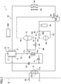
FIG. 1 is a piping diagram illustrating an example of a configuration of a refrigeration cycle apparatus of a present embodiment. -
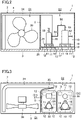
FIG. 2 is a front view illustrating the configuration of the refrigeration cycle apparatus. -
FIG. 3 is a plan view illustrating the configuration of the refrigeration cycle apparatus. - As illustrated in
FIG. 1 , a refrigeration cycle apparatus (1) is configured to heat a target fluid. The target fluid is water. The refrigeration cycle apparatus (1) is configured to supply the heated water to an apparatus utilizing the heated water, such as a hot water tank, a coil for indoor heating, or a coil for floor heating. The refrigeration cycle apparatus (1) is configured to cool the target fluid. The target fluid is water. The refrigeration cycle apparatus (1) is configured to supply the cooled water to an apparatus utilizing the cooled water, such as a coil for indoor cooling. The refrigeration cycle apparatus (1) includes a refrigerant circuit (30) and a control unit (100). - The refrigerant circuit (30) includes a first compressor (10), a second compressor (20), a four-way switching valve (33), a heat-source-side heat exchanger (34), a check valve bridge (35), an expansion valve (36), a utilization-side heat exchanger (37), an accumulator (38), and an intermediate heat exchanger (45).
- The refrigerant circuit (30) is filled with a refrigerant. The refrigerant circuit (30) performs a refrigeration cycle by circulating the refrigerant therein. The refrigerant is, for example, a refrigerant R410A, R32, or R407C.
- The first compressor (10) is, for example, a scroll compressor. The first compressor (10) is provided on a discharge side of the second compressor (20). The first compressor (10) is connected with a first suction pipe (51) and a first discharge pipe (52). The first compressor (10) is configured to compress the refrigerant sucked therein and to discharge the refrigerant thus compressed. The first compressor (10) has a greater capacity than the second compressor (20).
- The number of rotations of the first compressor (10) is variable. For example, the number of rotations of a motor is changed by changing an output frequency of an inverter (not illustrated) connected to the first compressor (10). As a result, the number of rotations (operation frequency) of the first compressor (10) changes.
- The second compressor (20) is, for example, a scroll compressor. The second compressor (20) is provided on a suction side of the first compressor (10). The second compressor (20) is connected with a second suction pipe (53) and a second discharge pipe (54). By connecting an inlet end of the first suction pipe (51) with an outlet end of the second discharge pipe (54), a connection pipe (50) is configured. The second compressor (20) and the first compressor (10) are connected with each other in series via the connection pipe (50). The second compressor (20) is configured to compress the refrigerant sucked therein and discharge the refrigerant thus compressed.
- The number of rotations of the second compressor (20) is variable. For example, the number of rotations of a motor is changed by changing an output frequency of an inverter (not illustrated) connected to the second compressor (20). As a result, the number of rotations (operation frequency) of the second compressor (20) changes.
- The four-way switching valve (33) is a solenoid-controlled switching valve. The four-way switching valve (33) switches between a first state (the state indicated by the solid lines in
FIG. 1 ) and a second state (the state indicated by the dotted lines inFIG. 1 ). A first port (PI) is connected to the outlet end of the first discharge pipe (52). A second port (P2) is connected to the inlet end of second suction pipe (53). A third port (P3) communicates with a gas-side end of the heat-source-side heat exchanger (34). A fourth port (P4) communicates with a gas-side end of the utilization-side heat exchanger (37). - The heat-source-side heat exchanger (34) is an outdoor heat exchanger. In the vicinity of the heat-source-side heat exchanger (34), a fan (39) is provided. As a result of operation of the fan (39), heat exchange takes place between the refrigerant of the heat-source-side heat exchanger (34) and the outdoor air.
- The check valve bridge (35) includes four check valves (C). Each of the four check valves (C) allows the refrigerant to flow in the direction indicated by the arrows in
FIG. 1 , and restricts the refrigerant from flowing in the opposite direction. To an inlet side of the check valve bridge (35), one end of a main liquid pipe (55) is connected. To an outlet side of the check valve bridge (35), the other end of the main liquid pipe (55) is connected. The check valve bridge (35) communicates with a liquid-side end of the heat-source-side heat exchanger (34) and a liquid-side end of the utilization-side heat exchanger (37). - The expansion valve (36) expands the refrigerant to lower the pressure of the refrigerant. The expansion valve (36) is an electronic expansion valve whose opening degree is adjustable. The expansion valve (36) is connected to the main liquid pipe (55).
- The utilization-side heat exchanger (37) causes heat exchange between the refrigerant and the water. The utilization-side heat exchanger (37) includes a first channel (37a) and a second channel (37b). The first channel (37a) is a channel through which the refrigerant flows. The second channel (37b) is a channel through which the water flows. The second channel (37b) is connected to an intermediate portion of a utilization-side circuit (65) included in the apparatus utilizing the water (not illustrated). The utilization-side heat exchanger (37) causes heat exchange between the refrigerant flowing through the first channel (37a) and the water flowing through the second channel (37b).
- The accumulator (38) is connected to an intermediate portion of the second suction pipe (53). The accumulator (38) is a gas-liquid separator. Inside the accumulator (38), the refrigerant is separated into a liquid refrigerant and a gas refrigerant. The accumulator (38) is configured to allow only the gas refrigerant to flow out of the accumulator (38).
- A bypass circuit (60) includes a bypass piping (PB) and a bypass check valve (61). The bypass piping (PB) is connected between the second suction pipe (53) and the connection pipe (50). The bypass check valve (61) allows the refrigerant to flow in a direction from the second suction pipe (53) to the connection pipe (50), and restricts the refrigerant from flowing in the opposite direction.
- An injection circuit (40) is a circuit for supplying part of the refrigerant flowing through the main liquid pipe (55) to the suction side of the first compressor (10). The injection circuit (40) includes an injection piping (PJ), an injection expansion valve (41), and an open/close valve (42).
- The injection piping (PJ) has one end connected between the expansion valve (36) and the check valve bridge (35) in the main liquid pipe (55). The injection piping (PJ) has the other end branched into two ends, one of which is connected with the first suction pipe (51) and the other one of which is connected with a compression chamber in the course of compression of the first compressor (10).
- The injection expansion valve (41) is connected to a portion of the injection piping (PJ) upstream of the intermediate heat exchanger (45). The injection expansion valve (41) decompresses the refrigerant flowing through the injection piping (PJ).
- The open/close valve (42) is switchable between an open state and a closed state. When the open/close valve (42) is in the open state, part of the refrigerant flowing through the injection piping (PJ) is supplied to the suction side of the first compressor (10). When the open/close valve (42) is in the closed state, the refrigerant flowing through the injection piping (PJ) is supplied to the compression chamber in the course of compression of the first compressor (10).
- The intermediate heat exchanger (45) includes a third channel (45a) and a fourth channel (45b). The third channel (45a) is connected to an intermediate portion of the main liquid pipe (55). The fourth channel (45b) is connected to an intermediate portion of the injection piping (PJ). The intermediate heat exchanger (45) causes heat exchange between the refrigerant flowing through the third channel (45a) and the refrigerant flowing through the fourth channel (45b).
- The refrigeration cycle apparatus (1) includes various sensors, such as temperature sensors for detecting temperatures of the refrigerant etc. and pressure sensors for detecting pressures of the refrigerant etc. Signals indicative of detection results of the sensors are sent to the control unit (100).
- The refrigeration cycle apparatus (1) includes the control unit (100). The control unit (100) includes a microcomputer and a memory device storing software for operating the microcomputer.
- The control unit (100) is configured to control the refrigerant circuit (30) based on the signals from the various sensors and external control signals. The control unit (100) is configured to output control signals to the first compressor (10), the second compressor (20), the four-way switching valve (33), the expansion valve (36), the injection expansion valve (41), the open/close valve (42), and the like. The control unit (100) receives values detected by the various sensors.
- The refrigeration cycle apparatus (1) performs heating operation and cooling operation. The refrigeration cycle apparatus (1) is configured such that the first compressor (10) functions as a high-pressure compressor and the second compressor (20) functions as a low-pressure compressor.
- In the heating operation, a refrigeration cycle is performed in which the utilization-side heat exchanger (37) serves a condenser (a radiator) and the heat-source-side heat exchanger (34) serves as an evaporator. Specifically, the four-way switching valve (33) is placed in the first state.
- The refrigerant discharged from the first compressor (10) passes through the four-way switching valve (33), and dissipates heat to water to condense in the utilization-side heat exchanger (37). The refrigerant that has flowed out of the utilization-side heat exchanger (37) passes through the check valve bridge (35), and circulates through the main liquid pipe (55). The refrigerant circulating through the main liquid pipe (55) dissipates heat to the refrigerant flowing through the fourth channel (45b), and is supercooled, in the third channel (45a) of the intermediate heat exchanger (45). Thereafter, part of the refrigerant flowing through the main liquid pipe (55) flows into the injection piping (PJ), and the remaining part of the refrigerant is decompressed at the expansion valve (36) in the main liquid pipe (55).
- The refrigerant thus decompressed passes through the check valve bridge (35) and evaporates in the heat-source-side heat exchanger (34). The refrigerant that has flowed out of the heat-source-side heat exchanger (34) sequentially passes through the four-way switching valve (33) and the accumulator (38), and is sucked into the second compressor (20) and compressed. The refrigerant discharged from the second compressor (20) is sucked into the first compressor (10) and is compressed.
- On the other hand, the refrigerant that has flowed into the injection piping (PJ) is decompressed at the injection expansion valve (41), and absorbs heat from the refrigerant flowing through the third channel (45a) and evaporates in the fourth channel (45b) of the intermediate heat exchanger (45). Thereafter, the refrigerant flowing through the injection piping (PJ) is introduced into the first suction pipe (51) to the first compressor (10).
- In the cooling operation, a refrigeration cycle is performed in which the heat-source-side heat exchanger (34) serves as a condenser (a radiator) and the utilization-side heat exchanger (37) serves as an evaporator. Specifically, the four-way switching valve (33) is placed in the second state. An explanation of the flow of the refrigerant during the cooling operation is omitted.
- As illustrated in
FIGS. 2 and 3 , the refrigeration cycle apparatus (1) includes a housing (2). The housing (2) has a bottom member (3) and a cover member (4). - An interior of the housing (2) is partitioned into a heat exchange chamber (S1) and a machine chamber (S2) by a partition (5). The cover member (4) covers the heat exchange chamber (S1) and the machine chamber (S2). In the heat exchange chamber (SI), the heat-source-side heat exchanger (34) and the fan (39) are provided. As a result of operation of the fan (39), heat exchange takes place between the refrigerant flowing through the heat-source-side heat exchanger (34) and the outdoor air.
- In the machine chamber (S2), the devices illustrated within the virtual frame line in
FIG. 1 are provided. Specifically, the machine chamber (S2) accommodates the first compressor (10), the second compressor (20), and refrigerant circuit component parts (31) constituting the refrigerant circuit (30). Although not illustrated, the control unit (100) is located in the machine chamber (S2). - The first compressor (10) is supported by a first intermediate plate (15) through a plurality of first elastic members (11). Specifically, the first compressor (10) is provided with a first supporting leg (16). Between the first supporting legs (16) and the first intermediate plate (15), three first elastic members (11) are provided.
- The first elastic members (11) may be a single large piece or may be two or more separate pieces as long as the first elastic member (11) or the first elastic members (11) can support the first compressor (10). The first elastic members (11) are made of rubber or urethan.
- The first intermediate plate (15) is supported by the bottom member (3) of the housing (2) through a plurality of second elastic members (12). Between the first intermediate plate (15) and the bottom member (3), four second elastic members (12) are provided. The second elastic members (12) are provided at four corners of the first intermediate plate (15), respectively.
- The second elastic members (12) may be a single large piece or may be two or more separate pieces. The second elastic members (12) are made of rubber or urethan. The first elastic members (11) and the second elastic members (12) may be made from the same material or different materials, and may have the same spring constant or different spring constants.
- The first compressor (10) is placed on a double anti-vibration structure comprised of the first elastic members (11), the first intermediate plate (15), and the second elastic members (12). With this configuration, even if the first compressor (10) vibrates during the operation of the refrigeration cycle apparatus (1), transmission of the vibration and noise generation are reduced.
- The second compressor (20) is supported by a second intermediate plate (25) through the plurality of first elastic members (11). Specifically, the second compressor (20) is provided with a second supporting leg (26). Between the second supporting legs (26) and the second intermediate plate (25), three first elastic members (11) are provided.
- The first elastic members (11) may be a single large piece or may be two or more separate pieces as long as the first elastic member (11) or the first elastic members (11) can support the second compressor (20). The first elastic members (11) are made of rubber or urethan.
- The second intermediate plate (25) is supported by the bottom member (3) of the housing (2) through the plurality of second elastic members (12). Between the second intermediate plate (25) and the bottom member (3), four second elastic members (12) are provided. The second elastic members (12) are provided at four corners of the first intermediate plate (15), respectively.
- The second elastic members (12) may be a single large piece or may be two or more separate pieces. The second elastic members (12) are made of rubber or urethan. The first elastic members (11) and the second elastic members (12) may be made from the same material or different materials, and may have the same spring constant or different spring constants.
- The second compressor (20) is placed on a double anti-vibration structure comprised of the first elastic members (11), the second intermediate plate (25), and the second elastic members (12). With this configuration, even if the second compressor (20) vibrates during the operation of the refrigeration cycle apparatus (1), transmission of the vibration and noise generation are reduced.
- Thus, the first compressor (10) and the second compressor (20) vibrate independently of each other, and therefore resonance between the first intermediate plate (15) and the second intermediate plate (25) can be reduced.
- The first compressor (10) and the second compressor (20) are connected with each other via the connection pipe (50) with flexibility. The connection pipe (50) includes a first suction pipe (51) and a second discharge pipe (54). The connection pipe (50) may have a flexible structure by having a plurality of bent portions, for example. The connection pipe (50) may be configured with a flexible pipe or a bellows pipe.
- With this configuration, even if a positional displacement occurs between the first intermediate plate (15) and the second intermediate plate (25) due to the vibrations of the first compressor (10) and the second compressor (20), stress applied on the connection pipe (50) can be reduced.
- Since the first compressor (10) has a greater capacity than the second compressor (20), the first compressor (10) is heavier than the second compressor (20). The overall weight of the first intermediate plate (15) and the first compressor (10) is therefore greater than the overall weight of the second intermediate plate (25) and the second compressor (20).
- As illustrated in
FIG. 3 , a refrigerant circuit component part (31) constituting the refrigerant circuit (30) is placed on the first intermediate plate (15). In the example illustrated inFIG. 3 , the refrigerant circuit component part (31) is an accumulator (38). In this way, the accumulator (38) is placed on the first intermediate plate (15), which is included in the greater overall weight, to further increase the overall weight, thereby making it possible to improve the vibration isolation performance. - Another refrigerant circuit component part (31) is placed on the second intermediate plate (25). In the example illustrated in
FIG. 3 , the refrigerant circuit component part (31) is a utilization-side heat exchanger (37). In this way, the utilization-side heat exchanger (37) is placed on the second intermediate plate (25), which is included in the smaller overall weight, to increase the overall weight of the second intermediate plate (25) with relatively poorer vibration isolation performance, thereby making it possible to improve the vibration isolation performance. - Although in this embodiment a refrigerant circuit component part (31) is placed on each of the first intermediate plate (15) and the second intermediate plate (25), a refrigerant circuit component part (31) may be placed on only one of the intermediate plates.
- Although not illustrated in the drawings, refrigerant circuit component parts (31) other than the first compressor (10), the second compressor (20), the accumulator (38), and the utilization-side heat exchanger (37) may be arranged on the first intermediate plate (15) and second intermediate plate (25). Examples of the refrigerant circuit component parts (31) include the intermediate heat exchanger (45), the four-way switching valve (33), the check valve bridge (35), the expansion valve (36), the bypass check valve (61), etc.
- In a feature (1) of the embodiment, the first intermediate plate (15) and the second intermediate plate (25) are supported by the bottom member (3) through the plurality of second elastic members (12). The first compressor (10) and the second compressor (20) are supported by the first intermediate plate (15) and the second intermediate plate (25), respectively, through the plurality of first elastic members (11).
- According to the feature (1) of the embodiment, the first compressor (10) and the second compressor (20) vibrate independently of each other, and therefore the resonance between the first intermediate plate (15) and the second intermediate plate (25) can be reduced.
- In a feature (2) of the embodiment, a refrigerant circuit component part (31) is provided on at least one of the first intermediate plate (15) or the second intermediate plate (25).
- According to the feature (2) of the embodiment, the vibration can be reduced by increasing the overall weight of the intermediate plate with the refrigerant circuit component part (31) placed thereon.
- In a feature (3) of the embodiment, at least one of the refrigerant circuit component parts (31) is provided on the intermediate plate included in a greater one of the overall weight of the first intermediate plate (15) and the first compressor (10) and the overall weight of the second intermediate plate (25) and the second compressor (20).
- According to the feature (3) of the embodiment, a refrigerant circuit component part (31) is provided on the intermediate plate included in the greater overall weight to further increase the overall weight, thereby making it possible to further improve the vibration isolation performance.
- In a fourth feature of the embodiment, at least one of the refrigerant circuit component parts (31) is provided on the intermediate plate included in a smaller one of the overall weight of the first intermediate plate (15) and the first compressor (10) and the overall weight of the second intermediate plate (25) and the second compressor (20).
- According to the feature (4) of the embodiment, the refrigerant circuit component part (31) is provided on the intermediate plate included in the smaller overall weight to increase the overall weight of the intermediate plate with relatively poorer vibration isolation performance, thereby making it possible to improve the vibration isolation performance.
- In a feature (5) of the embodiment, a refrigerant circuit component part (31) is provided on each of the first intermediate plate (15) and the second intermediate plate (25).
- According to the feature (5) of the embodiment, the weights on the first intermediate plate (15) and the second intermediate plate (25) are increased, so that the vibrations transmitting to the housing (2) can be reduced.
- In a feature (6) of the embodiment, the first compressor (10) and the second compressor (20) are connected with the pipe (50) with flexibility.
- According to the feature (6) of the embodiment, even if a positional displacement occurs between the first intermediate plate (15) and the second intermediate plate (25) due to the vibrations of the first compressor (10) and the second compressor (20), stress applied on the pipe (50) can be reduced.
- The above-described embodiments may be modified as follows.
- Even though this embodiment describes a configuration with two compressors, the embodiment may be configured with three or more compressors. In this case, another intermediate plate is provided in addition to the first intermediate plate (15) and the second intermediate plate (25), and a compressor is provided on this intermediate plate.
- While the embodiments and variations have been described above, it will be understood that various changes in form and details can be made without departing from the spirit and scope of the claims. The above embodiments and variations may be appropriately combined or modified by replacing the elements thereof as long as the functions of the subject matters of the present disclosure are not impaired. In addition, the expressions of "first," "second," and "third" in the specification and claims are used to distinguish the terms to which these expressions are given, and do not limit the number and order of the terms.
- As described above, the present disclosure is useful for a refrigeration cycle apparatus.
-
- 1
- Refrigeration Cycle Apparatus
- 2
- Housing
- 3
- Bottom Member
- 10
- First Compressor
- 11
- First Elastic Member
- 12
- Second Elastic Member
- 15
- First Intermediate Plate
- 20
- Second Compressor
- 25
- Second Intermediate Plate
- 30
- Refrigerant Circuit
- 31
- Refrigerant Circuit Component Part
- 50
- Connection Pipe
Claims (6)
- A refrigeration cycle apparatus comprising: a housing (2) having a bottom member (3); and a plurality of compressors accommodated in the housing (2),the plurality of compressors at least including a first compressor (10) and a second compressor (20),the first compressor (10) and the second compressor (20) being supported by a first intermediate plate (15) and a second intermediate plate (25), respectively, through a plurality of first elastic members (11),the first intermediate plate (15) and the second intermediate plate (25) being supported by the bottom member (3) through a plurality of second elastic members (12).
- The refrigeration cycle apparatus of claim 1, wherein
at least one of refrigerant circuit component parts (31) constituting a refrigerant circuit (30) is provided on at least one of the first intermediate plate (15) or the second intermediate plate (25). - The refrigeration cycle apparatus of claim 2, wherein
at least one of the refrigerant circuit component parts (31) is provided on the first intermediate plate (15) or the second intermediate plate (25) that is included in a greater one of an overall weight of the first intermediate plate (15) and the first compressor (10) and an overall weight of the second intermediate plate (25) and the second compressor (20). - The refrigeration cycle apparatus of claim 2, wherein
at least one of the refrigerant circuit component parts (31) is provided on the first intermediate plate (15) or the second intermediate plate (25) that is included in a smaller one of an overall weight of the first intermediate plate (15) and the first compressor (10) and an overall weight of the second intermediate plate (25) and the second compressor (20). - The refrigeration cycle apparatus of claim 1, wherein
a refrigerant circuit component part (31) constituting a refrigerant circuit (30) is provided on each of the first intermediate plate (15) and the second intermediate plate (25). - The refrigeration cycle apparatus of any one of claims 1 to 5, wherein
the first compressor (10) and the second compressor (20) are connected with each other via a pipe (50) with flexibility.
Applications Claiming Priority (2)
| Application Number | Priority Date | Filing Date | Title |
|---|---|---|---|
| JP2020063772A JP7150775B2 (en) | 2020-03-31 | 2020-03-31 | refrigeration cycle equipment |
| PCT/JP2021/010685 WO2021200130A1 (en) | 2020-03-31 | 2021-03-16 | Refrigeration cycle device |
Publications (3)
| Publication Number | Publication Date |
|---|---|
| EP4113020A1 true EP4113020A1 (en) | 2023-01-04 |
| EP4113020A4 EP4113020A4 (en) | 2023-08-09 |
| EP4113020B1 EP4113020B1 (en) | 2024-08-14 |
Family
ID=77927752
Family Applications (1)
| Application Number | Title | Priority Date | Filing Date |
|---|---|---|---|
| EP21780800.5A Active EP4113020B1 (en) | 2020-03-31 | 2021-03-16 | Refrigeration cycle apparatus |
Country Status (7)
| Country | Link |
|---|---|
| US (1) | US12590737B2 (en) |
| EP (1) | EP4113020B1 (en) |
| JP (1) | JP7150775B2 (en) |
| CN (1) | CN115244338B (en) |
| AU (1) | AU2021247556B2 (en) |
| CA (1) | CA3171961A1 (en) |
| WO (1) | WO2021200130A1 (en) |
Families Citing this family (1)
| Publication number | Priority date | Publication date | Assignee | Title |
|---|---|---|---|---|
| CN114341570A (en) * | 2019-09-04 | 2022-04-12 | 大金工业株式会社 | Compressor unit and refrigeration device |
Family Cites Families (19)
| Publication number | Priority date | Publication date | Assignee | Title |
|---|---|---|---|---|
| JPH081386Y2 (en) * | 1989-05-29 | 1996-01-17 | 三菱電機株式会社 | Air conditioner |
| JPH0544963A (en) * | 1991-01-17 | 1993-02-23 | Mitsubishi Electric Corp | Air-conditioner |
| US5277554A (en) * | 1992-11-13 | 1994-01-11 | Copeland Corporation | Tandem compressor mounting system |
| US5306121A (en) * | 1993-04-23 | 1994-04-26 | Carrier Corporation | Compressor tiered mounting arrangement |
| BE1010122A3 (en) * | 1996-03-19 | 1998-01-06 | Atlas Copco Airpower Nv | COMPRESSOR DEVICE. |
| JP2000111202A (en) | 1998-10-06 | 2000-04-18 | Toshiba Corp | Air conditioner |
| US6354558B1 (en) * | 1998-11-20 | 2002-03-12 | Carrier Corporation | Compressor mounting |
| JP2000161817A (en) * | 1998-11-24 | 2000-06-16 | Funai Electric Co Ltd | Vibration attenuation device of piping for compressor |
| JP2000283600A (en) * | 1999-03-30 | 2000-10-13 | Toshiba Corp | Air conditioner |
| US6260373B1 (en) * | 2000-02-16 | 2001-07-17 | American Standard International Inc. | Heat exchanger with double vibration isolation |
| WO2003038278A2 (en) * | 2001-10-29 | 2003-05-08 | Hebert Thomas H | Multiple compressor common circuit structure design |
| CN2575568Y (en) * | 2002-10-16 | 2003-09-24 | 广东科龙电器股份有限公司 | Observing device for vertical kiln |
| JP3838440B2 (en) * | 2004-09-21 | 2006-10-25 | 木村工機株式会社 | Built-in water heat source heat pump air conditioner |
| JP2010243033A (en) * | 2009-04-03 | 2010-10-28 | Mitsubishi Electric Corp | Heat pump outdoor unit |
| CN102753913B (en) * | 2010-02-15 | 2015-10-21 | 东芝开利株式会社 | Air conditioner |
| JP5561243B2 (en) * | 2011-06-09 | 2014-07-30 | 株式会社デンソー | Refrigeration cycle |
| US9181940B2 (en) * | 2012-03-23 | 2015-11-10 | Bitzer Kuehlmaschinenbau Gmbh | Compressor baseplate with stiffening ribs for increased oil volume and rail mounting without spacers |
| JP2015114030A (en) * | 2013-12-11 | 2015-06-22 | 日立アプライアンス株式会社 | Output unit of air conditioner |
| JP6677267B2 (en) | 2018-03-30 | 2020-04-08 | ダイキン工業株式会社 | Refrigeration cycle device |
-
2020
- 2020-03-31 JP JP2020063772A patent/JP7150775B2/en active Active
-
2021
- 2021-03-16 EP EP21780800.5A patent/EP4113020B1/en active Active
- 2021-03-16 CN CN202180019791.0A patent/CN115244338B/en active Active
- 2021-03-16 AU AU2021247556A patent/AU2021247556B2/en active Active
- 2021-03-16 CA CA3171961A patent/CA3171961A1/en active Pending
- 2021-03-16 WO PCT/JP2021/010685 patent/WO2021200130A1/en not_active Ceased
-
2022
- 2022-09-30 US US17/956,931 patent/US12590737B2/en active Active
Also Published As
| Publication number | Publication date |
|---|---|
| CA3171961A1 (en) | 2021-10-07 |
| EP4113020A4 (en) | 2023-08-09 |
| JP7150775B2 (en) | 2022-10-11 |
| WO2021200130A1 (en) | 2021-10-07 |
| EP4113020B1 (en) | 2024-08-14 |
| AU2021247556B2 (en) | 2025-05-08 |
| US12590737B2 (en) | 2026-03-31 |
| CN115244338B (en) | 2024-09-10 |
| AU2021247556A1 (en) | 2022-10-13 |
| CN115244338A (en) | 2022-10-25 |
| JP2021162219A (en) | 2021-10-11 |
| US20230020042A1 (en) | 2023-01-19 |
Similar Documents
| Publication | Publication Date | Title |
|---|---|---|
| EP4113019B1 (en) | Refrigeration cycle apparatus | |
| AU2016201491B9 (en) | Air conditioning apparatus | |
| US12590737B2 (en) | Refrigeration cycle apparatus | |
| JP6444538B2 (en) | Compressor support device, outdoor unit of refrigeration cycle apparatus, and refrigeration cycle apparatus | |
| EP2614972A1 (en) | Updating method for vehicle air conditioning device and vehicle air conditioning device | |
| JP2018096609A (en) | Compressor unit and outdoor unit equipped with the same | |
| EP3470674A1 (en) | Compressor unit and outdoor unit provided with same | |
| US20250020373A1 (en) | Refrigeration cycle apparatus | |
| CN114938658B (en) | Outdoor unit of refrigeration cycle device | |
| WO2016147785A1 (en) | Refrigerant compression device and refrigeration cycle device | |
| EP4428456A1 (en) | Outdoor unit of air conditioner | |
| EP4679001A1 (en) | Heat pump unit | |
| KR101450546B1 (en) | Air conditioning system | |
| JP7293783B2 (en) | Outdoor unit for air conditioner | |
| EP4400784A1 (en) | Refrigerant flow path module and heat source unit | |
| EP3486578A1 (en) | Refrigeration device | |
| JP2025073326A (en) | Compressors and refrigeration/air conditioning equipment | |
| JP2008151370A (en) | Compressor unit | |
| JP2021181843A (en) | Outdoor unit for refrigeration cycle device | |
| CN120769967A (en) | Outdoor unit | |
| KR20230075271A (en) | Heat exchange assembly and outdoor unit including the same | |
| KR20220049908A (en) | Air Conditioner | |
| KR20070052548A (en) | Air conditioner |
Legal Events
| Date | Code | Title | Description |
|---|---|---|---|
| STAA | Information on the status of an ep patent application or granted ep patent |
Free format text: STATUS: THE INTERNATIONAL PUBLICATION HAS BEEN MADE |
|
| PUAI | Public reference made under article 153(3) epc to a published international application that has entered the european phase |
Free format text: ORIGINAL CODE: 0009012 |
|
| STAA | Information on the status of an ep patent application or granted ep patent |
Free format text: STATUS: REQUEST FOR EXAMINATION WAS MADE |
|
| 17P | Request for examination filed |
Effective date: 20220926 |
|
| AK | Designated contracting states |
Kind code of ref document: A1 Designated state(s): AL AT BE BG CH CY CZ DE DK EE ES FI FR GB GR HR HU IE IS IT LI LT LU LV MC MK MT NL NO PL PT RO RS SE SI SK SM TR |
|
| RAP3 | Party data changed (applicant data changed or rights of an application transferred) |
Owner name: DAIKIN INDUSTRIES, LTD. |
|
| DAV | Request for validation of the european patent (deleted) | ||
| DAX | Request for extension of the european patent (deleted) | ||
| P01 | Opt-out of the competence of the unified patent court (upc) registered |
Effective date: 20230525 |
|
| A4 | Supplementary search report drawn up and despatched |
Effective date: 20230706 |
|
| RIC1 | Information provided on ipc code assigned before grant |
Ipc: F25B 41/40 20210101ALI20230630BHEP Ipc: F24F 13/20 20060101ALI20230630BHEP Ipc: F24F 1/30 20110101ALI20230630BHEP Ipc: F24F 1/12 20110101AFI20230630BHEP |
|
| GRAP | Despatch of communication of intention to grant a patent |
Free format text: ORIGINAL CODE: EPIDOSNIGR1 |
|
| STAA | Information on the status of an ep patent application or granted ep patent |
Free format text: STATUS: GRANT OF PATENT IS INTENDED |
|
| INTG | Intention to grant announced |
Effective date: 20240403 |
|
| GRAS | Grant fee paid |
Free format text: ORIGINAL CODE: EPIDOSNIGR3 |
|
| GRAA | (expected) grant |
Free format text: ORIGINAL CODE: 0009210 |
|
| STAA | Information on the status of an ep patent application or granted ep patent |
Free format text: STATUS: THE PATENT HAS BEEN GRANTED |
|
| AK | Designated contracting states |
Kind code of ref document: B1 Designated state(s): AL AT BE BG CH CY CZ DE DK EE ES FI FR GB GR HR HU IE IS IT LI LT LU LV MC MK MT NL NO PL PT RO RS SE SI SK SM TR |
|
| REG | Reference to a national code |
Ref country code: GB Ref legal event code: FG4D |
|
| REG | Reference to a national code |
Ref country code: CH Ref legal event code: EP |
|
| REG | Reference to a national code |
Ref country code: DE Ref legal event code: R096 Ref document number: 602021017288 Country of ref document: DE |
|
| REG | Reference to a national code |
Ref country code: IE Ref legal event code: FG4D |
|
| REG | Reference to a national code |
Ref country code: LT Ref legal event code: MG9D |
|
| REG | Reference to a national code |
Ref country code: NL Ref legal event code: MP Effective date: 20240814 |
|
| PG25 | Lapsed in a contracting state [announced via postgrant information from national office to epo] |
Ref country code: NO Free format text: LAPSE BECAUSE OF FAILURE TO SUBMIT A TRANSLATION OF THE DESCRIPTION OR TO PAY THE FEE WITHIN THE PRESCRIBED TIME-LIMIT Effective date: 20241114 |
|
| REG | Reference to a national code |
Ref country code: AT Ref legal event code: MK05 Ref document number: 1713610 Country of ref document: AT Kind code of ref document: T Effective date: 20240814 |
|
| PG25 | Lapsed in a contracting state [announced via postgrant information from national office to epo] |
Ref country code: PT Free format text: LAPSE BECAUSE OF FAILURE TO SUBMIT A TRANSLATION OF THE DESCRIPTION OR TO PAY THE FEE WITHIN THE PRESCRIBED TIME-LIMIT Effective date: 20241216 Ref country code: FI Free format text: LAPSE BECAUSE OF FAILURE TO SUBMIT A TRANSLATION OF THE DESCRIPTION OR TO PAY THE FEE WITHIN THE PRESCRIBED TIME-LIMIT Effective date: 20240814 Ref country code: NL Free format text: LAPSE BECAUSE OF FAILURE TO SUBMIT A TRANSLATION OF THE DESCRIPTION OR TO PAY THE FEE WITHIN THE PRESCRIBED TIME-LIMIT Effective date: 20240814 Ref country code: PL Free format text: LAPSE BECAUSE OF FAILURE TO SUBMIT A TRANSLATION OF THE DESCRIPTION OR TO PAY THE FEE WITHIN THE PRESCRIBED TIME-LIMIT Effective date: 20240814 Ref country code: GR Free format text: LAPSE BECAUSE OF FAILURE TO SUBMIT A TRANSLATION OF THE DESCRIPTION OR TO PAY THE FEE WITHIN THE PRESCRIBED TIME-LIMIT Effective date: 20241115 |
|
| PG25 | Lapsed in a contracting state [announced via postgrant information from national office to epo] |
Ref country code: BG Free format text: LAPSE BECAUSE OF FAILURE TO SUBMIT A TRANSLATION OF THE DESCRIPTION OR TO PAY THE FEE WITHIN THE PRESCRIBED TIME-LIMIT Effective date: 20240814 |
|
| PG25 | Lapsed in a contracting state [announced via postgrant information from national office to epo] |
Ref country code: LV Free format text: LAPSE BECAUSE OF FAILURE TO SUBMIT A TRANSLATION OF THE DESCRIPTION OR TO PAY THE FEE WITHIN THE PRESCRIBED TIME-LIMIT Effective date: 20240814 |
|
| PG25 | Lapsed in a contracting state [announced via postgrant information from national office to epo] |
Ref country code: AT Free format text: LAPSE BECAUSE OF FAILURE TO SUBMIT A TRANSLATION OF THE DESCRIPTION OR TO PAY THE FEE WITHIN THE PRESCRIBED TIME-LIMIT Effective date: 20240814 Ref country code: IS Free format text: LAPSE BECAUSE OF FAILURE TO SUBMIT A TRANSLATION OF THE DESCRIPTION OR TO PAY THE FEE WITHIN THE PRESCRIBED TIME-LIMIT Effective date: 20241214 |
|
| PG25 | Lapsed in a contracting state [announced via postgrant information from national office to epo] |
Ref country code: HR Free format text: LAPSE BECAUSE OF FAILURE TO SUBMIT A TRANSLATION OF THE DESCRIPTION OR TO PAY THE FEE WITHIN THE PRESCRIBED TIME-LIMIT Effective date: 20240814 |
|
| PG25 | Lapsed in a contracting state [announced via postgrant information from national office to epo] |
Ref country code: RS Free format text: LAPSE BECAUSE OF FAILURE TO SUBMIT A TRANSLATION OF THE DESCRIPTION OR TO PAY THE FEE WITHIN THE PRESCRIBED TIME-LIMIT Effective date: 20241114 Ref country code: ES Free format text: LAPSE BECAUSE OF FAILURE TO SUBMIT A TRANSLATION OF THE DESCRIPTION OR TO PAY THE FEE WITHIN THE PRESCRIBED TIME-LIMIT Effective date: 20240814 |
|
| PG25 | Lapsed in a contracting state [announced via postgrant information from national office to epo] |
Ref country code: RS Free format text: LAPSE BECAUSE OF FAILURE TO SUBMIT A TRANSLATION OF THE DESCRIPTION OR TO PAY THE FEE WITHIN THE PRESCRIBED TIME-LIMIT Effective date: 20241114 Ref country code: PT Free format text: LAPSE BECAUSE OF FAILURE TO SUBMIT A TRANSLATION OF THE DESCRIPTION OR TO PAY THE FEE WITHIN THE PRESCRIBED TIME-LIMIT Effective date: 20241216 Ref country code: PL Free format text: LAPSE BECAUSE OF FAILURE TO SUBMIT A TRANSLATION OF THE DESCRIPTION OR TO PAY THE FEE WITHIN THE PRESCRIBED TIME-LIMIT Effective date: 20240814 Ref country code: NO Free format text: LAPSE BECAUSE OF FAILURE TO SUBMIT A TRANSLATION OF THE DESCRIPTION OR TO PAY THE FEE WITHIN THE PRESCRIBED TIME-LIMIT Effective date: 20241114 Ref country code: NL Free format text: LAPSE BECAUSE OF FAILURE TO SUBMIT A TRANSLATION OF THE DESCRIPTION OR TO PAY THE FEE WITHIN THE PRESCRIBED TIME-LIMIT Effective date: 20240814 Ref country code: LV Free format text: LAPSE BECAUSE OF FAILURE TO SUBMIT A TRANSLATION OF THE DESCRIPTION OR TO PAY THE FEE WITHIN THE PRESCRIBED TIME-LIMIT Effective date: 20240814 Ref country code: IS Free format text: LAPSE BECAUSE OF FAILURE TO SUBMIT A TRANSLATION OF THE DESCRIPTION OR TO PAY THE FEE WITHIN THE PRESCRIBED TIME-LIMIT Effective date: 20241214 Ref country code: HR Free format text: LAPSE BECAUSE OF FAILURE TO SUBMIT A TRANSLATION OF THE DESCRIPTION OR TO PAY THE FEE WITHIN THE PRESCRIBED TIME-LIMIT Effective date: 20240814 Ref country code: GR Free format text: LAPSE BECAUSE OF FAILURE TO SUBMIT A TRANSLATION OF THE DESCRIPTION OR TO PAY THE FEE WITHIN THE PRESCRIBED TIME-LIMIT Effective date: 20241115 Ref country code: FI Free format text: LAPSE BECAUSE OF FAILURE TO SUBMIT A TRANSLATION OF THE DESCRIPTION OR TO PAY THE FEE WITHIN THE PRESCRIBED TIME-LIMIT Effective date: 20240814 Ref country code: ES Free format text: LAPSE BECAUSE OF FAILURE TO SUBMIT A TRANSLATION OF THE DESCRIPTION OR TO PAY THE FEE WITHIN THE PRESCRIBED TIME-LIMIT Effective date: 20240814 Ref country code: BG Free format text: LAPSE BECAUSE OF FAILURE TO SUBMIT A TRANSLATION OF THE DESCRIPTION OR TO PAY THE FEE WITHIN THE PRESCRIBED TIME-LIMIT Effective date: 20240814 Ref country code: AT Free format text: LAPSE BECAUSE OF FAILURE TO SUBMIT A TRANSLATION OF THE DESCRIPTION OR TO PAY THE FEE WITHIN THE PRESCRIBED TIME-LIMIT Effective date: 20240814 |
|
| PG25 | Lapsed in a contracting state [announced via postgrant information from national office to epo] |
Ref country code: RO Free format text: LAPSE BECAUSE OF FAILURE TO SUBMIT A TRANSLATION OF THE DESCRIPTION OR TO PAY THE FEE WITHIN THE PRESCRIBED TIME-LIMIT Effective date: 20240814 Ref country code: SM Free format text: LAPSE BECAUSE OF FAILURE TO SUBMIT A TRANSLATION OF THE DESCRIPTION OR TO PAY THE FEE WITHIN THE PRESCRIBED TIME-LIMIT Effective date: 20240814 Ref country code: DK Free format text: LAPSE BECAUSE OF FAILURE TO SUBMIT A TRANSLATION OF THE DESCRIPTION OR TO PAY THE FEE WITHIN THE PRESCRIBED TIME-LIMIT Effective date: 20240814 |
|
| PG25 | Lapsed in a contracting state [announced via postgrant information from national office to epo] |
Ref country code: EE Free format text: LAPSE BECAUSE OF FAILURE TO SUBMIT A TRANSLATION OF THE DESCRIPTION OR TO PAY THE FEE WITHIN THE PRESCRIBED TIME-LIMIT Effective date: 20240814 |
|
| PG25 | Lapsed in a contracting state [announced via postgrant information from national office to epo] |
Ref country code: CZ Free format text: LAPSE BECAUSE OF FAILURE TO SUBMIT A TRANSLATION OF THE DESCRIPTION OR TO PAY THE FEE WITHIN THE PRESCRIBED TIME-LIMIT Effective date: 20240814 |
|
| PG25 | Lapsed in a contracting state [announced via postgrant information from national office to epo] |
Ref country code: IT Free format text: LAPSE BECAUSE OF FAILURE TO SUBMIT A TRANSLATION OF THE DESCRIPTION OR TO PAY THE FEE WITHIN THE PRESCRIBED TIME-LIMIT Effective date: 20240814 Ref country code: SK Free format text: LAPSE BECAUSE OF FAILURE TO SUBMIT A TRANSLATION OF THE DESCRIPTION OR TO PAY THE FEE WITHIN THE PRESCRIBED TIME-LIMIT Effective date: 20240814 |
|
| REG | Reference to a national code |
Ref country code: DE Ref legal event code: R097 Ref document number: 602021017288 Country of ref document: DE |
|
| PLBE | No opposition filed within time limit |
Free format text: ORIGINAL CODE: 0009261 |
|
| STAA | Information on the status of an ep patent application or granted ep patent |
Free format text: STATUS: NO OPPOSITION FILED WITHIN TIME LIMIT |
|
| 26N | No opposition filed |
Effective date: 20250515 |
|
| PG25 | Lapsed in a contracting state [announced via postgrant information from national office to epo] |
Ref country code: SE Free format text: LAPSE BECAUSE OF FAILURE TO SUBMIT A TRANSLATION OF THE DESCRIPTION OR TO PAY THE FEE WITHIN THE PRESCRIBED TIME-LIMIT Effective date: 20240814 |
|
| PG25 | Lapsed in a contracting state [announced via postgrant information from national office to epo] |
Ref country code: MC Free format text: LAPSE BECAUSE OF FAILURE TO SUBMIT A TRANSLATION OF THE DESCRIPTION OR TO PAY THE FEE WITHIN THE PRESCRIBED TIME-LIMIT Effective date: 20240814 |
|
| REG | Reference to a national code |
Ref country code: CH Ref legal event code: H13 Free format text: ST27 STATUS EVENT CODE: U-0-0-H10-H13 (AS PROVIDED BY THE NATIONAL OFFICE) Effective date: 20251023 |
|
| PG25 | Lapsed in a contracting state [announced via postgrant information from national office to epo] |
Ref country code: LU Free format text: LAPSE BECAUSE OF NON-PAYMENT OF DUE FEES Effective date: 20250316 |
|
| REG | Reference to a national code |
Ref country code: BE Ref legal event code: MM Effective date: 20250331 |
|
| PG25 | Lapsed in a contracting state [announced via postgrant information from national office to epo] |
Ref country code: BE Free format text: LAPSE BECAUSE OF NON-PAYMENT OF DUE FEES Effective date: 20250331 |
|
| PG25 | Lapsed in a contracting state [announced via postgrant information from national office to epo] |
Ref country code: CH Free format text: LAPSE BECAUSE OF NON-PAYMENT OF DUE FEES Effective date: 20250331 |
|
| PG25 | Lapsed in a contracting state [announced via postgrant information from national office to epo] |
Ref country code: IE Free format text: LAPSE BECAUSE OF NON-PAYMENT OF DUE FEES Effective date: 20250316 |
|
| PGFP | Annual fee paid to national office [announced via postgrant information from national office to epo] |
Ref country code: GB Payment date: 20260202 Year of fee payment: 6 |
|
| PGFP | Annual fee paid to national office [announced via postgrant information from national office to epo] |
Ref country code: DE Payment date: 20260128 Year of fee payment: 6 |
|
| PGFP | Annual fee paid to national office [announced via postgrant information from national office to epo] |
Ref country code: FR Payment date: 20260209 Year of fee payment: 6 |