EP4112963A1 - Electromagnetic clutch - Google Patents
Electromagnetic clutch Download PDFInfo
- Publication number
- EP4112963A1 EP4112963A1 EP21759813.5A EP21759813A EP4112963A1 EP 4112963 A1 EP4112963 A1 EP 4112963A1 EP 21759813 A EP21759813 A EP 21759813A EP 4112963 A1 EP4112963 A1 EP 4112963A1
- Authority
- EP
- European Patent Office
- Prior art keywords
- cover
- rotor
- armature plate
- foreign matter
- electromagnetic clutch
- Prior art date
- Legal status (The legal status is an assumption and is not a legal conclusion. Google has not performed a legal analysis and makes no representation as to the accuracy of the status listed.)
- Granted
Links
Images




Classifications
-
- F—MECHANICAL ENGINEERING; LIGHTING; HEATING; WEAPONS; BLASTING
- F16—ENGINEERING ELEMENTS AND UNITS; GENERAL MEASURES FOR PRODUCING AND MAINTAINING EFFECTIVE FUNCTIONING OF MACHINES OR INSTALLATIONS; THERMAL INSULATION IN GENERAL
- F16D—COUPLINGS FOR TRANSMITTING ROTATION; CLUTCHES; BRAKES
- F16D27/00—Magnetically- or electrically- actuated clutches; Control or electric circuits therefor
- F16D27/10—Magnetically- or electrically- actuated clutches; Control or electric circuits therefor with an electromagnet not rotating with a clutching member, i.e. without collecting rings
- F16D27/108—Magnetically- or electrically- actuated clutches; Control or electric circuits therefor with an electromagnet not rotating with a clutching member, i.e. without collecting rings with axially movable clutching members
- F16D27/112—Magnetically- or electrically- actuated clutches; Control or electric circuits therefor with an electromagnet not rotating with a clutching member, i.e. without collecting rings with axially movable clutching members with flat friction surfaces, e.g. discs
-
- F—MECHANICAL ENGINEERING; LIGHTING; HEATING; WEAPONS; BLASTING
- F16—ENGINEERING ELEMENTS AND UNITS; GENERAL MEASURES FOR PRODUCING AND MAINTAINING EFFECTIVE FUNCTIONING OF MACHINES OR INSTALLATIONS; THERMAL INSULATION IN GENERAL
- F16D—COUPLINGS FOR TRANSMITTING ROTATION; CLUTCHES; BRAKES
- F16D2300/00—Special features for couplings or clutches
- F16D2300/08—Details or arrangements of sealings not provided for in group F16D3/84
Definitions
- the present invention relates to an electromagnetic clutch used to interrupt a rotational force transmitted from a rotational power source such as an engine and a motor to a compressor for an air conditioner for a vehicle, and more particularly to an electromagnetic clutch whose front side is covered with a cover.
- a general electromagnetic clutch used in a compressor for an air conditioner for a vehicle includes: a rotor that is rotatably externally fitted, via a bearing, on an outer periphery of a cylindrical part of a housing supporting a drive shaft and that rotates by receiving a rotational force from a rotational power source such as an engine or a motor; a hub that is coupled to the drive shaft so as not to be rotatable relative thereto and that rotates together with the drive shaft; an armature plate that is coupled to the hub and that is disposed to face a side end surface of the rotor with a slight gap therebetween; and an excitation coil that is accommodated in the inside of an annular space of the rotor.
- an installation place of the compressor may be, for example, a severe water-exposure environment with respect to the electromagnetic clutch, such as an environment in which the electromagnetic clutch is likely to be exposed to water, since the compressor is installed beside an engine of a rear side engine room of a bus and the electromagnetic clutch is oriented toward an outer side of the vehicle.
- the electromagnetic clutch when the electromagnetic clutch is exposed to water, the water may enter a bearing for smoothly rotating the rotor, so that an inside of the bearing may rust.
- an inside of the rear side engine room may be cleaned with high-pressure water by a high-pressure cleaning machine, and in this case, since the water is more likely to enter the bearing of the electromagnetic clutch, rust in the bearing is also likely to progress. Therefore, as shown in PTL 1, the electromagnetic clutch may be waterproofed by covering an entire front side end surface of the armature plate of the electromagnetic clutch with a cover.
- PTL 1 discloses a configuration in which a foreign matter discharging opening for discharging foreign matter such as the abrasion powder generated in the electromagnetic clutch to the outside is provided in the cover that covers the entire front side end surface of the armature plate of the electromagnetic clutch.
- an outer edge part of a circular plate part extends toward an outer periphery of the electromagnetic clutch from the foreign matter discharging opening. Therefore, for example, when the engine room of the bus is cleaned by the high-pressure cleaning machine as described above, the high-pressure water may hit a surface of the outer edge part on the outer periphery of the circular plate part of the cover than the foreign matter discharging opening and enter the electromagnetic clutch from the foreign matter discharging opening of the cover.
- the invention is made to solve the above problem, and an object of the invention is to provide an electromagnetic clutch capable of preventing water from entering the electromagnetic clutch from a foreign matter discharging part that discharges foreign matter such as abrasion powder to the outside, even when a cover that covers a front side end surface of an armature plate is provided with the foreign matter discharging part when the cover is attached.
- an electromagnetic clutch includes: a rotor rotatably supported by a housing of a compressor and configured to receive a rotational force from a rotational power source to rotate; a hub coupled to a drive shaft of the compressor so as not to be rotatable relative thereto and rotating together with the drive shaft; an armature plate coupled to the hub and having a rear side end surface disposed to face a friction wall of the rotor with a gap therebetween; an excitation coil supported by the housing of the compressor, accommodated in an inside of the rotor, and configured to generate an electromagnetic attraction force between the armature plate and the rotor; and a cover attached to the rotor and configured to cover a front side end surface of the armature plate, the cover including a top surface part disposed to face the front side end surface opposite to the rear side end surface of the armature plate and a cylindrical part extending from the top surface part.
- a foreign matter discharging part that discharges foreign matter in the cover to an outside of the cover and toward a rear side of the compressor is formed on the cylindrical part of the cover.
- the rotational power source is, for example, an engine or a motor of an automobile.
- the foreign matter is, for example, abrasion powder generated by frictional engagement between the rotor and the armature plate.
- the cover covering the front side end surface of the armature plate of the electromagnetic clutch forms the foreign matter discharging part on the cylindrical part instead of the top surface part that is likely to be exposed to water from a front side, the water from the front side of the electromagnetic clutch can be prevented from entering the cover and further entering the electromagnetic clutch from the foreign matter discharging part.
- the foreign matter discharging part of the cover is formed to protrude outward from the cylindrical part, and includes a first opening facing a side peripheral surface side of the armature plate, a second opening facing the rear side of the compressor, and an internal space communicating with the first and second openings.
- the foreign matter in the cover of the electromagnetic clutch enters the internal space of the foreign matter discharging part from the first opening, and then is discharged to an outside of the electromagnetic clutch from the second opening, while the two openings of the foreign matter discharging part of the cover, through which the foreign matter enters and exits, are directed to the side peripheral surface side of the armature plate and the rear side of the compressor respectively, and therefore, even if the electromagnetic clutch is covered with water from the front side end surface side of the armature plate of the electromagnetic clutch, the water can be prevented from entering the cover and further entering the electromagnetic clutch from the foreign matter discharging part.
- the rotor includes a plurality of ring-shaped constituting members, and adjacent constituting members of the plurality of constituting members are coupled to each other via a ring-shaped magnetism shielding part made of a non-magnetic body.
- the plurality of ring-shaped constituting members are, for example, a friction wall constituting member having a friction surface facing a friction surface of the armature plate, an outer peripheral wall constituting member positioned on an outer side than the friction wall constituting member, and an inner peripheral wall constituting member positioned on an inner side than the friction wall constituting member. Accordingly, the abrasion powder generated by the frictional engagement between the rotor and the armature plate can be prevented from entering between the rotor and a coil case.
- the foreign matter discharging part of the cover that covers the front side end surface of the armature plate of the electromagnetic clutch is formed on a side peripheral surface of the cylindrical part.
- the two openings of the foreign matter discharging part of the cover face the side peripheral surface side of the armature plate and the rear side of the compressor, respectively. Therefore, even if the electromagnetic clutch is covered with water from the front side of the electromagnetic clutch, the water can be prevented from entering the cover and further entering the electromagnetic clutch from the foreign matter discharging part and rusting the bearing, unlike the case where the foreign matter discharging part is formed on the top surface part of the cover.
- the abrasion powder generated by the frictional engagement between the rotor and the armature plate can be prevented from entering a space between the rotor and the coil case.
- a compressor 100 shown in FIG. 1 is a refrigerant compressor for an air conditioner of a large-sized vehicle such as a bus or a track. It is noted that the type of the compressor according to the invention is not limited to such a refrigerant compressor for an air conditioner of a large-sized vehicle. Although not shown, the invention is also applicable to, for example, a compressor constituting a refrigeration cycle of an air conditioner of a passenger vehicle.
- a left side of the figure is a front side
- a right side of the figure is a rear side.
- the compressor 100 shown FIG. 1 will be described as an example of a compressor equipped with an electromagnetic clutch 1 to which the invention is applied, and includes a cylinder block 101, a front head 102 assembled to a front side of the cylinder block 101 via a valve plate, and a rear head 103 assembled to a rear side of the cylinder block 101 via a valve plate.
- the cylinder block 101, the front head 102, and the rear head 103 are fastened by fastening bolts 104 (only heads thereof are shown) along an axial direction thereof to form a housing 105 of the compressor 100.
- a plurality of cylinder bores and a crank chamber are defined in the cylinder block 101 of the housing 105.
- a drive shaft 106 (shown by a broken line in FIG. 5 ) passing through the crank chamber is rotatably supported in the cylinder block 101, so that a swash plate (not shown) disposed in the crank chamber is rotated by rotation of the drive shaft 106 to reciprocate a double-head piston (not shown) in each of the cylinder bores.
- the electromagnetic clutch 1 is attached to one end of the drive shaft 106.
- the electromagnetic clutch 1 shown in FIGS. 2 and 3 is used to interrupt a rotational force transmitted from a rotational power source (not shown) such as an engine or a motor to the compressor 100.
- a rotational power source such as an engine or a motor
- FIGS. 2 and 3 a left side of the figure is the front side, and a right side of the figure is the rear side.
- the electromagnetic clutch 1 includes: a rotor 3 that is rotatably supported via a bearing 2 such as a ball bearing, by a cylindrical part 102a (shown in FIG. 3 ) protruding from an end part of the front head 102 around the drive shaft 106 of the compressor 100; a hub 8 that is coupled to the drive shaft 106 of the compressor 100 so as not to be rotatable relative thereto and rotates together with the drive shaft 106; an armature plate 4 that is disposed to face the rotor 3 with a slight gap therebetween in an axial direction and fixed to the hub 8; and an excitation coil 7 that is supported by the housing 105 of the compressor 100, accommodated in the inside of the rotor 3, and generates an electromagnetic attraction force between the armature plate 4 and the rotor 3.
- a bearing 2 such as a ball bearing
- a leaf spring mechanism 11 that urges the armature plate 4 in a direction away from the rotor 3 is used, as a mechanism that prevents the armature plate 4 from coming into contact with the rotor 3 when the excitation coil 7 is not energized, between the hub 8 and the armature plate 4.
- the rotor 3 shown as a single body in FIG. 4 is a magnetic body except for non-magnetic bodies 34 and 35 described below, is provided with the bearing 2 on an inner periphery thereof, and is rotatably mounted on an outer periphery of the cylindrical part 102a that extends from the front head 102 of the compressor 100 via the bearing 2 so as to allow the drive shaft 106 to be inserted therethrough.
- the rotor 3 has a friction wall 3a on an opposite side (a front side) to the compressor 100, and a front side end surface of the friction wall 3a is formed in a flat shape substantially perpendicular to an axial center of the rotor 3 and has a friction surface facing the armature plate 4.
- the rotor 3 includes a ring-shaped friction wall constituting member 31 having the friction wall 3a, a ring-shaped outer peripheral wall constituting member 32 disposed on an outer peripheral side than the friction wall constituting member 31 and having an outer peripheral wall 3b extending laterally (in an axial direction of the drive shaft 106) toward the rear side, a ring-shaped inner peripheral wall constituting member 33 disposed on an inner peripheral side than the friction wall constituting member 31 and having an inner peripheral wall 3c extending laterally (in the axial direction of the drive shaft 106) toward the rear side, the ring-shaped outer non-magnetic body 34 connecting the friction wall constituting member 31 with the outer peripheral wall constituting member 32, and the ring-shaped outer non-magnetic body 35 connecting the friction wall constituting member 31 with the inner peripheral wall constituting member 33.
- the constituting members 31, 32, and 33 are made of an ironbased magnetic material.
- the non-magnetic bodies 34 and 35 are made of an ironbased magnetic material.
- the non-magnetic bodies 34 and 35 are formed in a concentric shape disposed at a predetermined interval around a central axis of the rotor 3 so that the non-magnetic body 34 is located on an outer side and the non-magnetic body 35 is located on an inner side.
- a thin ring-shaped friction member 36 is disposed on a front side of the outer non-magnetic body 34.
- a front side end surface of the friction member 36 is flat and is located on the same plane as that of a friction surface of the friction wall 3a.
- a front side end surface of the inner non-magnetic body 35 is located at a position recessed from the friction surface of the friction wall 3a and a front side end surface of the outer peripheral wall constituting member 32, so that a step part is formed between the friction wall constituting member 31 and the outer peripheral wall constituting member 32 of the rotor 3.
- the bearing 2 is fixed to an inner peripheral side of the inner peripheral wall 3c of the inner peripheral wall constituting member 33 constituting the rotor 3.
- An annular space 5 of which a rear side is opened is formed between the outer peripheral wall 3b of the outer peripheral wall constituting member 32 and the inner peripheral wall 3c of the inner peripheral wall constituting member 33, and the annular space 5 accommodates, via a predetermined clearance, a coil case 12 accommodating the excitation coil 7. Accordingly, the rotor 3 is rotatable along the excitation coil 7 (the coil case 12) without being in sliding contact with the coil case 12.
- a belt groove 9 including a plurality of V-shaped grooves around which a belt (not shown) for transmitting the rotational force from the rotational power source is wound is formed in an outer peripheral side of the outer peripheral wall 3b of the outer peripheral wall constituting member 32.
- the armature plate 4 shown as a single body in FIG. 5 is formed in a disk shape, is coupled to the leaf spring mechanism 11, and has a rear side end surface 4a disposed to face the friction surface of the friction wall 3a of the rotor 3 with a slight gap therebetween.
- the rear side end surface 4a is formed in a flat shape substantially perpendicular to the axial center of the rotor 3, and forms a friction surface facing the friction surface and the like of the friction wall 3a of the rotor 3.
- a plurality of arc-shaped slit holes 41 are formed as a magnetism shielding part that shields magnetism generated by energizing the excitation coil 7 described below. These slit holes 41 penetrate the armature plate 4 in the axial direction of the drive shaft 106, and therefore are disposed along a circumference of a circle centered on a central axis of the armature plate 4.
- the excitation coil 7 is accommodated in the coil case 12.
- the coil case 12 is formed of an annular iron container, has an annular groove 12a whose one end is opened, and accommodates the excitation coil 7 in the annular groove 12a.
- the annular groove 12a is filled with an epoxy resin material 13 to fix the excitation coil 7.
- the coil case 12 is attached to the front head 102 of the compressor 100.
- the rotor 3 in order to prevent the bearing 2 from rusting due to the electromagnetic clutch 1 being exposed to water from the front side, the rotor 3 is provided with, on the outer peripheral wall constituting member 32, a flange-shaped protruding wall 3d protruding further to the outer peripheral side than the outer peripheral wall 3b, and a waterproof cover 20 is mainly attached to a front side of the protruding wall 3d. That is, in the protruding wall 3d of the rotor 3, a plurality of (six in the embodiment) screw holes 37 (shown in FIG. 4 ) through which fixtures 23 such as screws described below are inserted are formed.
- the cover 20 attached to the rotor 3 basically includes a top surface part 20a whose inner peripheral surface faces side end surfaces of the armature plate 4 and the hub 8, a cylindrical part 20b extending from a peripheral edge of the top surface part 20a toward a rear side, and a flange 20c protruding outward from an end of the cylindrical part 20b in an extending direction, and covers an entire front side end surface 4b and a side peripheral surface of the armature plate 4.
- Intervals with a predetermined width are formed between an inner surface of the top surface part 20a of the cover 20 and the side end surfaces of the armature plate 4 and the hub 8, and between an inner peripheral surface of the cylindrical part 20b of the cover 20 and an outer peripheral surface of the armature plate 4 so as not to bring the cover 20 into contact with the armature plate 4 and the hub 8 when the cover 20 rotates in synchronization with the rotor 3.
- the top surface part 20a of the cover 20 is formed with a plurality of (five in the embodiment) bulging parts 21 bulging in a substantially oval shape from an end surface of the top surface 20a toward a front side.
- the bulging parts 21 radially extend from a center of the top surface part 20a of the cover 20 toward an outer periphery, and intervals between the bulging parts 21 are uniform. In this way, by forming the bulging parts 21 on the top surface part 20a of the cover 20, the rigidity of the top surface part 20a is improved, and generation of abnormal noise from the top surface part 20a is prevented.
- a plurality of (six in the embodiment) through holes 22 through which the fixtures 23 are inserted are formed at positions on the same axis as the screw holes 37 of the rotor 3 and in an extending direction of the bulging parts 21.
- each of the foreign matter discharging parts 25 is formed between adjacent bulging parts 21 from a viewpoint of facilitating the formation of the cover 20.
- Each of the foreign matter discharging parts 25 is formed to protrude outward from the cylindrical part 20b of the cover 20, and includes an opening 25a opened to an armature plate 4 side on a front side of the side end surface of the armature plate 4, an opening 25b facing a rear side, and an internal space 25c communicating with both the opening 25a and the opening 25b.
- a sufficient interval is provided between the opening 25b of the foreign matter discharging part 25 and the flange 20c of the cover 20 so that the abrasion powder can be smoothly discharged from the opening 25b.
- a thin wall part is erected in a U shape that blocks a front side and opens a rear side from a peripheral edge of the opening 25a formed in the cylindrical part 20b, and then extends toward the rear side in a manner of covering the opening 25a to provide a function as an eave. That is, an outer shape of the foreign matter discharging part 25 is a substantially 1/4 spherical shape having a hollow inside.
- the foreign matter discharging parts 25 and the through holes 22 are disposed so as to be shifted from each other in a circumferential direction of the cover 20.
- the abrasion powder can be taken into the internal space 25c from the opening 25a of each of the foreign matter discharging parts 25 and discharged from the opening 25b.
- a wall part surrounding the internal space 25c of each of the foreign matter discharging parts 25 functions as an eave that blocks a front side of the internal space 25c (surrounds a front side of the opening 25b), even if the electromagnetic clutch 1 is exposed to water from the front side, the water can be prevented from entering the cover 20 and further entering the electromagnetic clutch 1 from the foreign matter discharging parts 25.
- the magnetism shielding part of the rotor 3 is made of a ring-shaped non-magnetic body, a foreign matter such as the abrasion powder can be prevented from entering a space between the rotor 3 and the coil case 12.
- a foreign matter such as the abrasion powder
- the space between the rotor 3 and the cover 20 is surrounded, since the foreign matter discharging parts 25 are formed on the cover 20, there is no possibility that the foreign matter stays inside the cover 20.
- the magnetism shielding part of the rotor 3 can be formed in a ring shape, a problem that magnetic leakage due to a bridge disposed between the slit holes occurs can be eliminated, as compared with a case where the magnetism shielding part of the rotor 3 is formed by a slit hole having a through hole shape.
- the magnetism shielding part of the rotor 3 shown as a single body in FIG. 4 is formed by the non-magnetic bodies 34 and 35
- the magnetism shielding part is not limited to the configuration. Even in a case where the magnetism shielding part of the rotor 3 is formed by the slit hole (not shown) as the magnetism shielding part of the armature plate 4, with a structure in which the cover 20 covers the front side end surface 4b of the armature plate 4, by applying the foreign matter discharging parts 25 of the invention to the cover 20, the abrasion powder can be discharged from the foreign matter discharging parts 25 of the cover 20, and the abrasion powder can be prevented from staying inside the cover while preventing water from entering the electromagnetic clutch 1 from the foreign matter discharging parts 25.
Landscapes
- Engineering & Computer Science (AREA)
- General Engineering & Computer Science (AREA)
- Physics & Mathematics (AREA)
- Electromagnetism (AREA)
- Mechanical Engineering (AREA)
- Compressors, Vaccum Pumps And Other Relevant Systems (AREA)
Abstract
Description
- The present invention relates to an electromagnetic clutch used to interrupt a rotational force transmitted from a rotational power source such as an engine and a motor to a compressor for an air conditioner for a vehicle, and more particularly to an electromagnetic clutch whose front side is covered with a cover.
- For example, as disclosed in
PTL 1, a general electromagnetic clutch used in a compressor for an air conditioner for a vehicle includes: a rotor that is rotatably externally fitted, via a bearing, on an outer periphery of a cylindrical part of a housing supporting a drive shaft and that rotates by receiving a rotational force from a rotational power source such as an engine or a motor; a hub that is coupled to the drive shaft so as not to be rotatable relative thereto and that rotates together with the drive shaft; an armature plate that is coupled to the hub and that is disposed to face a side end surface of the rotor with a slight gap therebetween; and an excitation coil that is accommodated in the inside of an annular space of the rotor. - Depending on the type and purpose of a vehicle, an installation place of the compressor may be, for example, a severe water-exposure environment with respect to the electromagnetic clutch, such as an environment in which the electromagnetic clutch is likely to be exposed to water, since the compressor is installed beside an engine of a rear side engine room of a bus and the electromagnetic clutch is oriented toward an outer side of the vehicle. In this way, when the electromagnetic clutch is exposed to water, the water may enter a bearing for smoothly rotating the rotor, so that an inside of the bearing may rust. In addition, in the bus, an inside of the rear side engine room may be cleaned with high-pressure water by a high-pressure cleaning machine, and in this case, since the water is more likely to enter the bearing of the electromagnetic clutch, rust in the bearing is also likely to progress. Therefore, as shown in
PTL 1, the electromagnetic clutch may be waterproofed by covering an entire front side end surface of the armature plate of the electromagnetic clutch with a cover. - On the other hand, in the electromagnetic clutch, since the rotor and the armature plate are frictionally engaged with each other, abrasion power is generated from friction surfaces of the rotor and the armature plate. In order to prevent the abrasion powder from accumulating in the electromagnetic clutch and causing a problem with respect to an operation of the clutch, it is required to provide a configuration for discharging the abrasion powder from the inside of the electromagnetic clutch to the outside when the entire front side end surface of the armature plate of the electromagnetic clutch is covered with the cover. Therefore,
PTL 1 discloses a configuration in which a foreign matter discharging opening for discharging foreign matter such as the abrasion powder generated in the electromagnetic clutch to the outside is provided in the cover that covers the entire front side end surface of the armature plate of the electromagnetic clutch. - PTL 1:
JP-A-2009-281579 - However, in the configuration of the cover disclosed in
PTL 1, as shown in FIGS. 3A, 3B, and4 ofPTL 1, an outer edge part of a circular plate part extends toward an outer periphery of the electromagnetic clutch from the foreign matter discharging opening. Therefore, for example, when the engine room of the bus is cleaned by the high-pressure cleaning machine as described above, the high-pressure water may hit a surface of the outer edge part on the outer periphery of the circular plate part of the cover than the foreign matter discharging opening and enter the electromagnetic clutch from the foreign matter discharging opening of the cover. - The invention is made to solve the above problem, and an object of the invention is to provide an electromagnetic clutch capable of preventing water from entering the electromagnetic clutch from a foreign matter discharging part that discharges foreign matter such as abrasion powder to the outside, even when a cover that covers a front side end surface of an armature plate is provided with the foreign matter discharging part when the cover is attached. Solution to Problem
- In order to achieve the above object, an electromagnetic clutch according to
claim 1 includes: a rotor rotatably supported by a housing of a compressor and configured to receive a rotational force from a rotational power source to rotate; a hub coupled to a drive shaft of the compressor so as not to be rotatable relative thereto and rotating together with the drive shaft; an armature plate coupled to the hub and having a rear side end surface disposed to face a friction wall of the rotor with a gap therebetween; an excitation coil supported by the housing of the compressor, accommodated in an inside of the rotor, and configured to generate an electromagnetic attraction force between the armature plate and the rotor; and a cover attached to the rotor and configured to cover a front side end surface of the armature plate, the cover including a top surface part disposed to face the front side end surface opposite to the rear side end surface of the armature plate and a cylindrical part extending from the top surface part. A foreign matter discharging part that discharges foreign matter in the cover to an outside of the cover and toward a rear side of the compressor is formed on the cylindrical part of the cover. The rotational power source is, for example, an engine or a motor of an automobile. The foreign matter is, for example, abrasion powder generated by frictional engagement between the rotor and the armature plate. - Accordingly, since the cover covering the front side end surface of the armature plate of the electromagnetic clutch forms the foreign matter discharging part on the cylindrical part instead of the top surface part that is likely to be exposed to water from a front side, the water from the front side of the electromagnetic clutch can be prevented from entering the cover and further entering the electromagnetic clutch from the foreign matter discharging part.
- In the electromagnetic clutch according to
claim 2, the foreign matter discharging part of the cover is formed to protrude outward from the cylindrical part, and includes a first opening facing a side peripheral surface side of the armature plate, a second opening facing the rear side of the compressor, and an internal space communicating with the first and second openings. - Accordingly, the foreign matter in the cover of the electromagnetic clutch enters the internal space of the foreign matter discharging part from the first opening, and then is discharged to an outside of the electromagnetic clutch from the second opening, while the two openings of the foreign matter discharging part of the cover, through which the foreign matter enters and exits, are directed to the side peripheral surface side of the armature plate and the rear side of the compressor respectively, and therefore, even if the electromagnetic clutch is covered with water from the front side end surface side of the armature plate of the electromagnetic clutch, the water can be prevented from entering the cover and further entering the electromagnetic clutch from the foreign matter discharging part.
- In the electromagnetic clutch according to
claim 3, the rotor includes a plurality of ring-shaped constituting members, and adjacent constituting members of the plurality of constituting members are coupled to each other via a ring-shaped magnetism shielding part made of a non-magnetic body. The plurality of ring-shaped constituting members are, for example, a friction wall constituting member having a friction surface facing a friction surface of the armature plate, an outer peripheral wall constituting member positioned on an outer side than the friction wall constituting member, and an inner peripheral wall constituting member positioned on an inner side than the friction wall constituting member. Accordingly, the abrasion powder generated by the frictional engagement between the rotor and the armature plate can be prevented from entering between the rotor and a coil case. - As described above, according to the invention, the foreign matter discharging part of the cover that covers the front side end surface of the armature plate of the electromagnetic clutch is formed on a side peripheral surface of the cylindrical part. In addition, the two openings of the foreign matter discharging part of the cover face the side peripheral surface side of the armature plate and the rear side of the compressor, respectively. Therefore, even if the electromagnetic clutch is covered with water from the front side of the electromagnetic clutch, the water can be prevented from entering the cover and further entering the electromagnetic clutch from the foreign matter discharging part and rusting the bearing, unlike the case where the foreign matter discharging part is formed on the top surface part of the cover.
- In particular, according to the invention of
claim 3, the abrasion powder generated by the frictional engagement between the rotor and the armature plate can be prevented from entering a space between the rotor and the coil case. -
- [
FIG. 1] FIG. 1 is a side view showing an external appearance of a configuration in which a cover according to the invention is attached to an electromagnetic clutch in an example of a compressor equipped with the electromagnetic clutch to which the invention is applied. - [
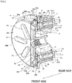
FIG. 2] FIG. 2 is a cross-sectional view of a configuration in which the cover according to the invention is attached to the electromagnetic clutch as view obliquely from a front side. - [
FIG. 3] FIG. 3 is a cross-sectional view of the configuration in which the cover according to the invention is attached to the electromagnetic clutch as viewed from a side. - [
FIG. 4] FIG. 4 is an explanatory view showing an outline of a configuration of a rotor according to the invention used in the electromagnetic clutch, in which (a) ofFIG. 4 is a front view of the rotor, and (b) ofFIG. 4 is a cross-sectional view taken along a line I-I in (a) ofFIG. 4 . - [
FIG. 5] FIG. 5 is an explanatory view showing an outline of a configuration of an armature plate used in the electromagnetic clutch, in which (a) ofFIG. 5 is a front view of the armature plate, and (b) ofFIG. 5 is a cross-sectional view taken along a line II-II in (a) ofFIG. 5 . - [
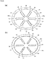
FIG. 6 ] (a) ofFIG. 6 is a front view of the cover according to the invention, and (b) ofFIG. 6 is a back view of the cover according to the invention. - [
FIG. 7 ] (a) ofFIG. 7 is a perspective view of the cover according to the invention as viewed obliquely from the front side, and (b) ofFIG. 7 is a perspective view of the cover according to the invention as viewed obliquely from a rear side. - Hereinafter, embodiments of the invention will be described with reference to the accompanying drawings.
- A
compressor 100 shown inFIG. 1 is a refrigerant compressor for an air conditioner of a large-sized vehicle such as a bus or a track. It is noted that the type of the compressor according to the invention is not limited to such a refrigerant compressor for an air conditioner of a large-sized vehicle. Although not shown, the invention is also applicable to, for example, a compressor constituting a refrigeration cycle of an air conditioner of a passenger vehicle. InFIG. 1 , a left side of the figure is a front side, and a right side of the figure is a rear side. - The
compressor 100 shownFIG. 1 will be described as an example of a compressor equipped with anelectromagnetic clutch 1 to which the invention is applied, and includes acylinder block 101, afront head 102 assembled to a front side of thecylinder block 101 via a valve plate, and arear head 103 assembled to a rear side of thecylinder block 101 via a valve plate. Thecylinder block 101, thefront head 102, and therear head 103 are fastened by fastening bolts 104 (only heads thereof are shown) along an axial direction thereof to form ahousing 105 of thecompressor 100. - A plurality of cylinder bores and a crank chamber (not shown) are defined in the
cylinder block 101 of thehousing 105. A drive shaft 106 (shown by a broken line inFIG. 5 ) passing through the crank chamber is rotatably supported in thecylinder block 101, so that a swash plate (not shown) disposed in the crank chamber is rotated by rotation of thedrive shaft 106 to reciprocate a double-head piston (not shown) in each of the cylinder bores. As shown inFIG. 3 , theelectromagnetic clutch 1 is attached to one end of thedrive shaft 106. - The
electromagnetic clutch 1 shown inFIGS. 2 and3 is used to interrupt a rotational force transmitted from a rotational power source (not shown) such as an engine or a motor to thecompressor 100. InFIGS. 2 and3 , a left side of the figure is the front side, and a right side of the figure is the rear side. - As shown in
FIGS. 2 and3 , theelectromagnetic clutch 1 includes: arotor 3 that is rotatably supported via abearing 2 such as a ball bearing, by acylindrical part 102a (shown inFIG. 3 ) protruding from an end part of thefront head 102 around thedrive shaft 106 of thecompressor 100; ahub 8 that is coupled to thedrive shaft 106 of thecompressor 100 so as not to be rotatable relative thereto and rotates together with thedrive shaft 106; anarmature plate 4 that is disposed to face therotor 3 with a slight gap therebetween in an axial direction and fixed to thehub 8; and anexcitation coil 7 that is supported by thehousing 105 of thecompressor 100, accommodated in the inside of therotor 3, and generates an electromagnetic attraction force between thearmature plate 4 and therotor 3. In the embodiment, aleaf spring mechanism 11 that urges thearmature plate 4 in a direction away from therotor 3 is used, as a mechanism that prevents thearmature plate 4 from coming into contact with therotor 3 when theexcitation coil 7 is not energized, between thehub 8 and thearmature plate 4. - The
rotor 3 shown as a single body inFIG. 4 is a magnetic body except fornon-magnetic bodies bearing 2 on an inner periphery thereof, and is rotatably mounted on an outer periphery of thecylindrical part 102a that extends from thefront head 102 of thecompressor 100 via thebearing 2 so as to allow thedrive shaft 106 to be inserted therethrough. Therotor 3 has afriction wall 3a on an opposite side (a front side) to thecompressor 100, and a front side end surface of thefriction wall 3a is formed in a flat shape substantially perpendicular to an axial center of therotor 3 and has a friction surface facing thearmature plate 4. - In addition, in the embodiment, as shown in
FIGS. 2 to 4 (in particular,FIG. 4 ), therotor 3 includes a ring-shaped frictionwall constituting member 31 having thefriction wall 3a, a ring-shaped outer peripheralwall constituting member 32 disposed on an outer peripheral side than the frictionwall constituting member 31 and having an outerperipheral wall 3b extending laterally (in an axial direction of the drive shaft 106) toward the rear side, a ring-shaped inner peripheralwall constituting member 33 disposed on an inner peripheral side than the frictionwall constituting member 31 and having an innerperipheral wall 3c extending laterally (in the axial direction of the drive shaft 106) toward the rear side, the ring-shaped outernon-magnetic body 34 connecting the frictionwall constituting member 31 with the outer peripheralwall constituting member 32, and the ring-shaped outernon-magnetic body 35 connecting the frictionwall constituting member 31 with the inner peripheralwall constituting member 33. The constitutingmembers non-magnetic bodies - The
non-magnetic bodies rotor 3 so that thenon-magnetic body 34 is located on an outer side and thenon-magnetic body 35 is located on an inner side. A thin ring-shaped friction member 36 is disposed on a front side of the outernon-magnetic body 34. A front side end surface of thefriction member 36 is flat and is located on the same plane as that of a friction surface of thefriction wall 3a. A front side end surface of the innernon-magnetic body 35 is located at a position recessed from the friction surface of thefriction wall 3a and a front side end surface of the outer peripheralwall constituting member 32, so that a step part is formed between the frictionwall constituting member 31 and the outer peripheralwall constituting member 32 of therotor 3. - In addition, the
bearing 2 is fixed to an inner peripheral side of the innerperipheral wall 3c of the inner peripheralwall constituting member 33 constituting therotor 3. Anannular space 5 of which a rear side is opened is formed between the outerperipheral wall 3b of the outer peripheralwall constituting member 32 and the innerperipheral wall 3c of the inner peripheralwall constituting member 33, and theannular space 5 accommodates, via a predetermined clearance, acoil case 12 accommodating theexcitation coil 7. Accordingly, therotor 3 is rotatable along the excitation coil 7 (the coil case 12) without being in sliding contact with thecoil case 12. In addition, abelt groove 9 including a plurality of V-shaped grooves around which a belt (not shown) for transmitting the rotational force from the rotational power source is wound is formed in an outer peripheral side of the outerperipheral wall 3b of the outer peripheralwall constituting member 32. - The
armature plate 4 shown as a single body inFIG. 5 is formed in a disk shape, is coupled to theleaf spring mechanism 11, and has a rearside end surface 4a disposed to face the friction surface of thefriction wall 3a of therotor 3 with a slight gap therebetween. The rearside end surface 4a is formed in a flat shape substantially perpendicular to the axial center of therotor 3, and forms a friction surface facing the friction surface and the like of thefriction wall 3a of therotor 3. In addition, in thearmature plate 4, a plurality of arc-shaped slit holes 41 are formed as a magnetism shielding part that shields magnetism generated by energizing theexcitation coil 7 described below. These slit holes 41 penetrate thearmature plate 4 in the axial direction of thedrive shaft 106, and therefore are disposed along a circumference of a circle centered on a central axis of thearmature plate 4. - The
excitation coil 7 is accommodated in thecoil case 12. Thecoil case 12 is formed of an annular iron container, has anannular groove 12a whose one end is opened, and accommodates theexcitation coil 7 in theannular groove 12a. Theannular groove 12a is filled with anepoxy resin material 13 to fix theexcitation coil 7. Thecoil case 12 is attached to thefront head 102 of thecompressor 100. - In the present embodiment, in order to prevent the
bearing 2 from rusting due to theelectromagnetic clutch 1 being exposed to water from the front side, therotor 3 is provided with, on the outer peripheralwall constituting member 32, a flange-shaped protrudingwall 3d protruding further to the outer peripheral side than the outerperipheral wall 3b, and awaterproof cover 20 is mainly attached to a front side of the protrudingwall 3d. That is, in the protrudingwall 3d of therotor 3, a plurality of (six in the embodiment) screw holes 37 (shown inFIG. 4 ) through whichfixtures 23 such as screws described below are inserted are formed. - As shown in
FIGS. 1 to 3 ,6 , and7 , thecover 20 attached to therotor 3 basically includes atop surface part 20a whose inner peripheral surface faces side end surfaces of thearmature plate 4 and thehub 8, acylindrical part 20b extending from a peripheral edge of thetop surface part 20a toward a rear side, and aflange 20c protruding outward from an end of thecylindrical part 20b in an extending direction, and covers an entire frontside end surface 4b and a side peripheral surface of thearmature plate 4. - Intervals with a predetermined width are formed between an inner surface of the
top surface part 20a of thecover 20 and the side end surfaces of thearmature plate 4 and thehub 8, and between an inner peripheral surface of thecylindrical part 20b of thecover 20 and an outer peripheral surface of thearmature plate 4 so as not to bring thecover 20 into contact with thearmature plate 4 and thehub 8 when thecover 20 rotates in synchronization with therotor 3. - The
top surface part 20a of thecover 20 is formed with a plurality of (five in the embodiment) bulgingparts 21 bulging in a substantially oval shape from an end surface of thetop surface 20a toward a front side. The bulgingparts 21 radially extend from a center of thetop surface part 20a of thecover 20 toward an outer periphery, and intervals between the bulgingparts 21 are uniform. In this way, by forming the bulgingparts 21 on thetop surface part 20a of thecover 20, the rigidity of thetop surface part 20a is improved, and generation of abnormal noise from thetop surface part 20a is prevented. In theflange 20c, a plurality of (six in the embodiment) throughholes 22 through which thefixtures 23 are inserted are formed at positions on the same axis as the screw holes 37 of therotor 3 and in an extending direction of the bulgingparts 21. - In addition, in the electromagnetic clutch according to the invention, as a configuration for discharging abrasion powder generated by frictional coupling between the
armature plate 4 and therotor 3 to an outside of theelectromagnetic clutch 1, a plurality of (six in the embodiment) foreignmatter discharging parts 25 are formed on thecover 20. In the embodiment, each of the foreignmatter discharging parts 25 is formed between adjacent bulgingparts 21 from a viewpoint of facilitating the formation of thecover 20. - Six foreign
matter discharging parts 25 formed on thecylindrical part 20b of thecover 20 are disposed with equal intervals as shown in (a) ofFIG. 6 in the embodiment, but the number and arrangement of the foreignmatter discharging parts 25 are not necessarily limited thereto. It is preferable that three or more foreignmatter discharging parts 25 are disposed with the equal intervals in consideration of a balance when thecover 20 rotates together with therotor 3. - Each of the foreign
matter discharging parts 25 is formed to protrude outward from thecylindrical part 20b of thecover 20, and includes anopening 25a opened to anarmature plate 4 side on a front side of the side end surface of thearmature plate 4, anopening 25b facing a rear side, and aninternal space 25c communicating with both theopening 25a and theopening 25b. A sufficient interval is provided between the opening 25b of the foreignmatter discharging part 25 and theflange 20c of thecover 20 so that the abrasion powder can be smoothly discharged from theopening 25b. In order to form theinternal space 25c having theopenings opening 25a formed in thecylindrical part 20b, and then extends toward the rear side in a manner of covering theopening 25a to provide a function as an eave. That is, an outer shape of the foreignmatter discharging part 25 is a substantially 1/4 spherical shape having a hollow inside. - In order to prevent the foreign
matter discharging parts 25 from being an obstacle when thefixtures 23 are inserted from the front side into the throughholes 22 of thecover 20 in a state of abutting against therotor 3, as shown in (a) ofFIG. 6 , the foreignmatter discharging parts 25 and the throughholes 22 are disposed so as to be shifted from each other in a circumferential direction of thecover 20. - By forming such foreign
matter discharging parts 25 on thecylindrical part 20b of thecover 20, the abrasion powder can be taken into theinternal space 25c from theopening 25a of each of the foreignmatter discharging parts 25 and discharged from theopening 25b. - In addition, since a wall part surrounding the
internal space 25c of each of the foreignmatter discharging parts 25 functions as an eave that blocks a front side of theinternal space 25c (surrounds a front side of theopening 25b), even if theelectromagnetic clutch 1 is exposed to water from the front side, the water can be prevented from entering thecover 20 and further entering theelectromagnetic clutch 1 from the foreignmatter discharging parts 25. - In addition, since the magnetism shielding part of the
rotor 3 is made of a ring-shaped non-magnetic body, a foreign matter such as the abrasion powder can be prevented from entering a space between therotor 3 and thecoil case 12. Although the space between therotor 3 and thecover 20 is surrounded, since the foreignmatter discharging parts 25 are formed on thecover 20, there is no possibility that the foreign matter stays inside thecover 20. - In addition, since the magnetism shielding part of the
rotor 3 can be formed in a ring shape, a problem that magnetic leakage due to a bridge disposed between the slit holes occurs can be eliminated, as compared with a case where the magnetism shielding part of therotor 3 is formed by a slit hole having a through hole shape. - Although the example in which the magnetism shielding part of the
rotor 3 shown as a single body inFIG. 4 is formed by thenon-magnetic bodies rotor 3 is formed by the slit hole (not shown) as the magnetism shielding part of thearmature plate 4, with a structure in which thecover 20 covers the frontside end surface 4b of thearmature plate 4, by applying the foreignmatter discharging parts 25 of the invention to thecover 20, the abrasion powder can be discharged from the foreignmatter discharging parts 25 of thecover 20, and the abrasion powder can be prevented from staying inside the cover while preventing water from entering theelectromagnetic clutch 1 from the foreignmatter discharging parts 25. -
- 1 electromagnetic clutch
- 3 rotor
- 3a friction wall
- 31 friction wall constituting member (constituting member)
- 32 outer peripheral wall constituting member (constituting member)
- 33 inner peripheral wall constituting member (constituting member)
- 34 outer non-magnetic body (non-magnetic body)
- 35 inner non-magnetic body (non-magnetic body)
- 4 armature plate
- 4a rear side end surface
- 4b front side end surface
- 7 excitation coil
- 8 hub
- 20 cover
- 20a top surface part
- 20b cylindrical part
- 25 foreign matter removing part
- 25a opening (first opening)
- 25b opening (second opening)
- 25c internal space
- 100 compressor
- 105 housing
- 106 drive shaft
Claims (3)
- An electromagnetic clutch (1) comprising:a rotor (3) rotatably supported by a housing (105) of a compressor (100) and configured to receive a rotational force from a rotational power source to rotate;a hub (8) coupled to a drive shaft (106) of the compressor (100) so as not to be rotatable relative thereto and rotating together with the drive shaft (106);an armature plate (4) coupled to the hub (8) and having a rear side end surface (4a) disposed to face a friction wall (3a) of the rotor (3) with a gap therebetween;an excitation coil (7) supported by the housing (105) of the compressor (100), accommodated in an inside of the rotor (3), and configured to generate an electromagnetic attraction force between the armature plate (4) and the rotor (3); anda cover (20) attached to the rotor (3) and configured to cover a front side end surface (4b) of the armature plate (4), the cover (20) including a top surface part (20a) disposed to face the front side end surface (4b) opposite to the rear side end surface (4a) of the armature plate (4) and a cylindrical part (20b) extending from the top surface part (20a), characterized in thata foreign matter discharging part (25) that discharges foreign matter in the cover (20) to an outside of the cover (20) and toward a rear side of the compressor (100) is formed on the cylindrical part (20b) of the cover (20).
- The electromagnetic clutch (1) according to claim 1, wherein
the foreign matter discharging part (25) of the cover (20) is formed to protrude outward from the cylindrical part (20b), and includes a first opening (25a) facing a side peripheral surface side of the armature plate (4), a second opening (25b) facing the rear side of the compressor (100), and an internal space communicating (25c) with the first and second openings (25a, 25b). - The electromagnetic clutch (1) according to claim 1 or 2, wherein
the rotor (3) includes a plurality of ring-shaped constituting members (31, 32, 33), and adjacent constituting members of the plurality of constituting members (31, 32, 33) are coupled to each other via a ring-shaped magnetism shielding part (34, 35) made of a non-magnetic body.
Applications Claiming Priority (2)
| Application Number | Priority Date | Filing Date | Title |
|---|---|---|---|
| JP2020032622 | 2020-02-28 | ||
| PCT/JP2021/006086 WO2021172156A1 (en) | 2020-02-28 | 2021-02-18 | Electromagnetic clutch |
Publications (3)
| Publication Number | Publication Date |
|---|---|
| EP4112963A1 true EP4112963A1 (en) | 2023-01-04 |
| EP4112963A4 EP4112963A4 (en) | 2024-03-20 |
| EP4112963B1 EP4112963B1 (en) | 2026-01-28 |
Family
ID=77490935
Family Applications (1)
| Application Number | Title | Priority Date | Filing Date |
|---|---|---|---|
| EP21759813.5A Active EP4112963B1 (en) | 2020-02-28 | 2021-02-18 | Electromagnetic clutch |
Country Status (4)
| Country | Link |
|---|---|
| EP (1) | EP4112963B1 (en) |
| JP (1) | JP7430027B2 (en) |
| CN (1) | CN115516223B (en) |
| WO (1) | WO2021172156A1 (en) |
Family Cites Families (7)
| Publication number | Priority date | Publication date | Assignee | Title |
|---|---|---|---|---|
| JPS5937438U (en) * | 1982-09-01 | 1984-03-09 | サンデン株式会社 | electromagnetic clutch |
| JPS6359223U (en) * | 1986-10-07 | 1988-04-20 | ||
| JP2009281579A (en) * | 2008-05-26 | 2009-12-03 | Denso Corp | Electromagnetic clutch |
| JP5263129B2 (en) | 2009-11-23 | 2013-08-14 | 株式会社デンソー | Power transmission device |
| JP5928327B2 (en) | 2012-12-26 | 2016-06-01 | 株式会社デンソー | Electromagnetic clutch and manufacturing method thereof |
| CN203871957U (en) * | 2014-04-28 | 2014-10-08 | 日本电产株式会社 | Motor and fan |
| CN208123298U (en) * | 2018-03-12 | 2018-11-20 | 上汽通用五菱汽车股份有限公司 | A kind of drum brake and vehicle of waterproof |
-
2021
- 2021-02-18 CN CN202180016966.2A patent/CN115516223B/en active Active
- 2021-02-18 EP EP21759813.5A patent/EP4112963B1/en active Active
- 2021-02-18 WO PCT/JP2021/006086 patent/WO2021172156A1/en not_active Ceased
- 2021-02-18 JP JP2022503305A patent/JP7430027B2/en active Active
Also Published As
| Publication number | Publication date |
|---|---|
| EP4112963B1 (en) | 2026-01-28 |
| EP4112963A4 (en) | 2024-03-20 |
| CN115516223B (en) | 2025-10-17 |
| JP7430027B2 (en) | 2024-02-09 |
| JPWO2021172156A1 (en) | 2021-09-02 |
| CN115516223A (en) | 2022-12-23 |
| WO2021172156A1 (en) | 2021-09-02 |
Similar Documents
| Publication | Publication Date | Title |
|---|---|---|
| CA2360401C (en) | Magnetic driving pump | |
| US5952746A (en) | Electrical machine and method for mounting such electrical machine on a unit | |
| US5894746A (en) | Drive device for a front-loading washing machine | |
| US4499391A (en) | End bracket for motor | |
| JP3731702B2 (en) | Pulley unit | |
| US11041494B2 (en) | Co-rotating scroll compressor | |
| US4645432A (en) | Magnetic drive vehicle coolant pump | |
| US4355959A (en) | Rotation sensor of a swash-plate type compressor | |
| KR101933803B1 (en) | Motor equipped with a brake | |
| KR20150107654A (en) | Motor structure | |
| EP4112963B1 (en) | Electromagnetic clutch | |
| WO2016103600A1 (en) | Electromagnetic clutch | |
| JP4730664B2 (en) | In-wheel motor | |
| CN113691042A (en) | Inner rotor motor with housing rotating | |
| EP4047236B1 (en) | Electromagnetic clutch | |
| JP2014087122A (en) | Rotary electric machine | |
| US11143174B2 (en) | Compressor | |
| JPH0335891Y2 (en) | ||
| US20180115213A1 (en) | Electric motor for suppressing entry of foreign substances | |
| US5238094A (en) | Enclosed clutch assembly to reduce noise | |
| WO2019054218A1 (en) | Valve timing control device for internal combustion engine | |
| JP2009281579A (en) | Electromagnetic clutch | |
| JP6569600B2 (en) | Clutch and manufacturing method thereof | |
| JP3951669B2 (en) | Driving force transmission device | |
| KR20260005611A (en) | Rotor and electric compressor including the same |
Legal Events
| Date | Code | Title | Description |
|---|---|---|---|
| STAA | Information on the status of an ep patent application or granted ep patent |
Free format text: STATUS: THE INTERNATIONAL PUBLICATION HAS BEEN MADE |
|
| PUAI | Public reference made under article 153(3) epc to a published international application that has entered the european phase |
Free format text: ORIGINAL CODE: 0009012 |
|
| STAA | Information on the status of an ep patent application or granted ep patent |
Free format text: STATUS: REQUEST FOR EXAMINATION WAS MADE |
|
| 17P | Request for examination filed |
Effective date: 20220801 |
|
| AK | Designated contracting states |
Kind code of ref document: A1 Designated state(s): AL AT BE BG CH CY CZ DE DK EE ES FI FR GB GR HR HU IE IS IT LI LT LU LV MC MK MT NL NO PL PT RO RS SE SI SK SM TR |
|
| DAV | Request for validation of the european patent (deleted) | ||
| DAX | Request for extension of the european patent (deleted) | ||
| A4 | Supplementary search report drawn up and despatched |
Effective date: 20240219 |
|
| RIC1 | Information provided on ipc code assigned before grant |
Ipc: F16D 27/112 20060101AFI20240213BHEP |
|
| GRAP | Despatch of communication of intention to grant a patent |
Free format text: ORIGINAL CODE: EPIDOSNIGR1 |
|
| STAA | Information on the status of an ep patent application or granted ep patent |
Free format text: STATUS: GRANT OF PATENT IS INTENDED |
|
| INTG | Intention to grant announced |
Effective date: 20250820 |
|
| GRAS | Grant fee paid |
Free format text: ORIGINAL CODE: EPIDOSNIGR3 |
|
| GRAA | (expected) grant |
Free format text: ORIGINAL CODE: 0009210 |
|
| STAA | Information on the status of an ep patent application or granted ep patent |
Free format text: STATUS: THE PATENT HAS BEEN GRANTED |
|
| AK | Designated contracting states |
Kind code of ref document: B1 Designated state(s): AL AT BE BG CH CY CZ DE DK EE ES FI FR GB GR HR HU IE IS IT LI LT LU LV MC MK MT NL NO PL PT RO RS SE SI SK SM TR |
|
| REG | Reference to a national code |
Ref country code: CH Ref legal event code: F10 Free format text: ST27 STATUS EVENT CODE: U-0-0-F10-F00 (AS PROVIDED BY THE NATIONAL OFFICE) Effective date: 20260128 Ref country code: GB Ref legal event code: FG4D |
|
| REG | Reference to a national code |
Ref country code: DE Ref legal event code: R096 Ref document number: 602021046935 Country of ref document: DE |
|
| REG | Reference to a national code |
Ref country code: IE Ref legal event code: FG4D |
|
| REG | Reference to a national code |
Ref country code: CH Ref legal event code: W10 Free format text: ST27 STATUS EVENT CODE: U-0-0-W10-W00 (AS PROVIDED BY THE NATIONAL OFFICE) Effective date: 20260311 |
|
| RAP2 | Party data changed (patent owner data changed or rights of a patent transferred) |
Owner name: VALEO ELECTRIFICATION |
|
| PGFP | Annual fee paid to national office [announced via postgrant information from national office to epo] |
Ref country code: DE Payment date: 20260313 Year of fee payment: 6 |