EP4112952A1 - Manille de fixation d'un moteur d' aéronef comprenant un couple de revêtements antifriction encapsules, et aéronef comprenant une telle manille - Google Patents
Manille de fixation d'un moteur d' aéronef comprenant un couple de revêtements antifriction encapsules, et aéronef comprenant une telle manille Download PDFInfo
- Publication number
- EP4112952A1 EP4112952A1 EP22181436.1A EP22181436A EP4112952A1 EP 4112952 A1 EP4112952 A1 EP 4112952A1 EP 22181436 A EP22181436 A EP 22181436A EP 4112952 A1 EP4112952 A1 EP 4112952A1
- Authority
- EP
- European Patent Office
- Prior art keywords
- shackle
- zone
- coating
- ring
- bore
- Prior art date
- Legal status (The legal status is an assumption and is not a legal conclusion. Google has not performed a legal analysis and makes no representation as to the accuracy of the status listed.)
- Granted
Links
Images


Classifications
-
- F—MECHANICAL ENGINEERING; LIGHTING; HEATING; WEAPONS; BLASTING
- F16—ENGINEERING ELEMENTS AND UNITS; GENERAL MEASURES FOR PRODUCING AND MAINTAINING EFFECTIVE FUNCTIONING OF MACHINES OR INSTALLATIONS; THERMAL INSULATION IN GENERAL
- F16C—SHAFTS; FLEXIBLE SHAFTS; ELEMENTS OR CRANKSHAFT MECHANISMS; ROTARY BODIES OTHER THAN GEARING ELEMENTS; BEARINGS
- F16C11/00—Pivots; Pivotal connections
- F16C11/04—Pivotal connections
- F16C11/06—Ball-joints; Other joints having more than one degree of angular freedom, i.e. universal joints
- F16C11/0614—Ball-joints; Other joints having more than one degree of angular freedom, i.e. universal joints the female part of the joint being open on two sides
-
- B—PERFORMING OPERATIONS; TRANSPORTING
- B64—AIRCRAFT; AVIATION; COSMONAUTICS
- B64D—EQUIPMENT FOR FITTING IN OR TO AIRCRAFT; FLIGHT SUITS; PARACHUTES; ARRANGEMENT OR MOUNTING OF POWER PLANTS OR PROPULSION TRANSMISSIONS IN AIRCRAFT
- B64D27/00—Arrangement or mounting of power plants in aircraft; Aircraft characterised by the type or position of power plants
- B64D27/40—Arrangements for mounting power plants in aircraft
-
- B—PERFORMING OPERATIONS; TRANSPORTING
- B64—AIRCRAFT; AVIATION; COSMONAUTICS
- B64D—EQUIPMENT FOR FITTING IN OR TO AIRCRAFT; FLIGHT SUITS; PARACHUTES; ARRANGEMENT OR MOUNTING OF POWER PLANTS OR PROPULSION TRANSMISSIONS IN AIRCRAFT
- B64D27/00—Arrangement or mounting of power plants in aircraft; Aircraft characterised by the type or position of power plants
- B64D27/40—Arrangements for mounting power plants in aircraft
- B64D27/402—Arrangements for mounting power plants in aircraft comprising box like supporting frames, e.g. pylons or arrangements for embracing the power plant
-
- B—PERFORMING OPERATIONS; TRANSPORTING
- B64—AIRCRAFT; AVIATION; COSMONAUTICS
- B64D—EQUIPMENT FOR FITTING IN OR TO AIRCRAFT; FLIGHT SUITS; PARACHUTES; ARRANGEMENT OR MOUNTING OF POWER PLANTS OR PROPULSION TRANSMISSIONS IN AIRCRAFT
- B64D27/00—Arrangement or mounting of power plants in aircraft; Aircraft characterised by the type or position of power plants
- B64D27/40—Arrangements for mounting power plants in aircraft
- B64D27/404—Suspension arrangements specially adapted for supporting vertical loads
-
- C—CHEMISTRY; METALLURGY
- C23—COATING METALLIC MATERIAL; COATING MATERIAL WITH METALLIC MATERIAL; CHEMICAL SURFACE TREATMENT; DIFFUSION TREATMENT OF METALLIC MATERIAL; COATING BY VACUUM EVAPORATION, BY SPUTTERING, BY ION IMPLANTATION OR BY CHEMICAL VAPOUR DEPOSITION, IN GENERAL; INHIBITING CORROSION OF METALLIC MATERIAL OR INCRUSTATION IN GENERAL
- C23C—COATING METALLIC MATERIAL; COATING MATERIAL WITH METALLIC MATERIAL; SURFACE TREATMENT OF METALLIC MATERIAL BY DIFFUSION INTO THE SURFACE, BY CHEMICAL CONVERSION OR SUBSTITUTION; COATING BY VACUUM EVAPORATION, BY SPUTTERING, BY ION IMPLANTATION OR BY CHEMICAL VAPOUR DEPOSITION, IN GENERAL
- C23C30/00—Coating with metallic material characterised only by the composition of the metallic material, i.e. not characterised by the coating process
-
- F—MECHANICAL ENGINEERING; LIGHTING; HEATING; WEAPONS; BLASTING
- F16—ENGINEERING ELEMENTS AND UNITS; GENERAL MEASURES FOR PRODUCING AND MAINTAINING EFFECTIVE FUNCTIONING OF MACHINES OR INSTALLATIONS; THERMAL INSULATION IN GENERAL
- F16C—SHAFTS; FLEXIBLE SHAFTS; ELEMENTS OR CRANKSHAFT MECHANISMS; ROTARY BODIES OTHER THAN GEARING ELEMENTS; BEARINGS
- F16C11/00—Pivots; Pivotal connections
- F16C11/04—Pivotal connections
- F16C11/06—Ball-joints; Other joints having more than one degree of angular freedom, i.e. universal joints
- F16C11/0604—Construction of the male part
-
- F—MECHANICAL ENGINEERING; LIGHTING; HEATING; WEAPONS; BLASTING
- F16—ENGINEERING ELEMENTS AND UNITS; GENERAL MEASURES FOR PRODUCING AND MAINTAINING EFFECTIVE FUNCTIONING OF MACHINES OR INSTALLATIONS; THERMAL INSULATION IN GENERAL
- F16C—SHAFTS; FLEXIBLE SHAFTS; ELEMENTS OR CRANKSHAFT MECHANISMS; ROTARY BODIES OTHER THAN GEARING ELEMENTS; BEARINGS
- F16C11/00—Pivots; Pivotal connections
- F16C11/04—Pivotal connections
- F16C11/06—Ball-joints; Other joints having more than one degree of angular freedom, i.e. universal joints
- F16C11/0619—Ball-joints; Other joints having more than one degree of angular freedom, i.e. universal joints the female part comprising a blind socket receiving the male part
- F16C11/0623—Construction or details of the socket member
- F16C11/0628—Construction or details of the socket member with linings
-
- F—MECHANICAL ENGINEERING; LIGHTING; HEATING; WEAPONS; BLASTING
- F16—ENGINEERING ELEMENTS AND UNITS; GENERAL MEASURES FOR PRODUCING AND MAINTAINING EFFECTIVE FUNCTIONING OF MACHINES OR INSTALLATIONS; THERMAL INSULATION IN GENERAL
- F16C—SHAFTS; FLEXIBLE SHAFTS; ELEMENTS OR CRANKSHAFT MECHANISMS; ROTARY BODIES OTHER THAN GEARING ELEMENTS; BEARINGS
- F16C23/00—Bearings for exclusively rotary movement adjustable for aligning or positioning
- F16C23/02—Sliding-contact bearings
- F16C23/04—Sliding-contact bearings self-adjusting
- F16C23/043—Sliding-contact bearings self-adjusting with spherical surfaces, e.g. spherical plain bearings
- F16C23/045—Sliding-contact bearings self-adjusting with spherical surfaces, e.g. spherical plain bearings for radial load mainly, e.g. radial spherical plain bearings
-
- F—MECHANICAL ENGINEERING; LIGHTING; HEATING; WEAPONS; BLASTING
- F16—ENGINEERING ELEMENTS AND UNITS; GENERAL MEASURES FOR PRODUCING AND MAINTAINING EFFECTIVE FUNCTIONING OF MACHINES OR INSTALLATIONS; THERMAL INSULATION IN GENERAL
- F16C—SHAFTS; FLEXIBLE SHAFTS; ELEMENTS OR CRANKSHAFT MECHANISMS; ROTARY BODIES OTHER THAN GEARING ELEMENTS; BEARINGS
- F16C33/00—Parts of bearings; Special methods for making bearings or parts thereof
- F16C33/02—Parts of sliding-contact bearings
- F16C33/04—Brasses; Bushes; Linings
- F16C33/043—Sliding surface consisting mainly of ceramics, cermets or hard carbon, e.g. diamond like carbon [DLC]
-
- F—MECHANICAL ENGINEERING; LIGHTING; HEATING; WEAPONS; BLASTING
- F16—ENGINEERING ELEMENTS AND UNITS; GENERAL MEASURES FOR PRODUCING AND MAINTAINING EFFECTIVE FUNCTIONING OF MACHINES OR INSTALLATIONS; THERMAL INSULATION IN GENERAL
- F16C—SHAFTS; FLEXIBLE SHAFTS; ELEMENTS OR CRANKSHAFT MECHANISMS; ROTARY BODIES OTHER THAN GEARING ELEMENTS; BEARINGS
- F16C33/00—Parts of bearings; Special methods for making bearings or parts thereof
- F16C33/02—Parts of sliding-contact bearings
- F16C33/04—Brasses; Bushes; Linings
- F16C33/06—Sliding surface mainly made of metal
- F16C33/12—Structural composition; Use of special materials or surface treatments, e.g. for rust-proofing
- F16C33/122—Multilayer structures of sleeves, washers or liners
- F16C33/124—Details of overlays
-
- F—MECHANICAL ENGINEERING; LIGHTING; HEATING; WEAPONS; BLASTING
- F16—ENGINEERING ELEMENTS AND UNITS; GENERAL MEASURES FOR PRODUCING AND MAINTAINING EFFECTIVE FUNCTIONING OF MACHINES OR INSTALLATIONS; THERMAL INSULATION IN GENERAL
- F16C—SHAFTS; FLEXIBLE SHAFTS; ELEMENTS OR CRANKSHAFT MECHANISMS; ROTARY BODIES OTHER THAN GEARING ELEMENTS; BEARINGS
- F16C9/00—Bearings for crankshafts or connecting-rods; Attachment of connecting-rods
- F16C9/04—Connecting-rod bearings; Attachments thereof
-
- F—MECHANICAL ENGINEERING; LIGHTING; HEATING; WEAPONS; BLASTING
- F16—ENGINEERING ELEMENTS AND UNITS; GENERAL MEASURES FOR PRODUCING AND MAINTAINING EFFECTIVE FUNCTIONING OF MACHINES OR INSTALLATIONS; THERMAL INSULATION IN GENERAL
- F16C—SHAFTS; FLEXIBLE SHAFTS; ELEMENTS OR CRANKSHAFT MECHANISMS; ROTARY BODIES OTHER THAN GEARING ELEMENTS; BEARINGS
- F16C2204/00—Metallic materials; Alloys
- F16C2204/10—Alloys based on copper
-
- F—MECHANICAL ENGINEERING; LIGHTING; HEATING; WEAPONS; BLASTING
- F16—ENGINEERING ELEMENTS AND UNITS; GENERAL MEASURES FOR PRODUCING AND MAINTAINING EFFECTIVE FUNCTIONING OF MACHINES OR INSTALLATIONS; THERMAL INSULATION IN GENERAL
- F16C—SHAFTS; FLEXIBLE SHAFTS; ELEMENTS OR CRANKSHAFT MECHANISMS; ROTARY BODIES OTHER THAN GEARING ELEMENTS; BEARINGS
- F16C2204/00—Metallic materials; Alloys
- F16C2204/40—Alloys based on refractory metals
- F16C2204/42—Alloys based on titanium
-
- F—MECHANICAL ENGINEERING; LIGHTING; HEATING; WEAPONS; BLASTING
- F16—ENGINEERING ELEMENTS AND UNITS; GENERAL MEASURES FOR PRODUCING AND MAINTAINING EFFECTIVE FUNCTIONING OF MACHINES OR INSTALLATIONS; THERMAL INSULATION IN GENERAL
- F16C—SHAFTS; FLEXIBLE SHAFTS; ELEMENTS OR CRANKSHAFT MECHANISMS; ROTARY BODIES OTHER THAN GEARING ELEMENTS; BEARINGS
- F16C2204/00—Metallic materials; Alloys
- F16C2204/52—Alloys based on nickel, e.g. Inconel
-
- F—MECHANICAL ENGINEERING; LIGHTING; HEATING; WEAPONS; BLASTING
- F16—ENGINEERING ELEMENTS AND UNITS; GENERAL MEASURES FOR PRODUCING AND MAINTAINING EFFECTIVE FUNCTIONING OF MACHINES OR INSTALLATIONS; THERMAL INSULATION IN GENERAL
- F16C—SHAFTS; FLEXIBLE SHAFTS; ELEMENTS OR CRANKSHAFT MECHANISMS; ROTARY BODIES OTHER THAN GEARING ELEMENTS; BEARINGS
- F16C2206/00—Materials with ceramics, cermets, hard carbon or similar non-metallic hard materials as main constituents
- F16C2206/02—Carbon based material
- F16C2206/04—Diamond like carbon [DLC]
-
- F—MECHANICAL ENGINEERING; LIGHTING; HEATING; WEAPONS; BLASTING
- F16—ENGINEERING ELEMENTS AND UNITS; GENERAL MEASURES FOR PRODUCING AND MAINTAINING EFFECTIVE FUNCTIONING OF MACHINES OR INSTALLATIONS; THERMAL INSULATION IN GENERAL
- F16C—SHAFTS; FLEXIBLE SHAFTS; ELEMENTS OR CRANKSHAFT MECHANISMS; ROTARY BODIES OTHER THAN GEARING ELEMENTS; BEARINGS
- F16C2206/00—Materials with ceramics, cermets, hard carbon or similar non-metallic hard materials as main constituents
- F16C2206/80—Cermets, i.e. composites of ceramics and metal
- F16C2206/82—Cermets, i.e. composites of ceramics and metal based on tungsten carbide [WC]
-
- F—MECHANICAL ENGINEERING; LIGHTING; HEATING; WEAPONS; BLASTING
- F16—ENGINEERING ELEMENTS AND UNITS; GENERAL MEASURES FOR PRODUCING AND MAINTAINING EFFECTIVE FUNCTIONING OF MACHINES OR INSTALLATIONS; THERMAL INSULATION IN GENERAL
- F16C—SHAFTS; FLEXIBLE SHAFTS; ELEMENTS OR CRANKSHAFT MECHANISMS; ROTARY BODIES OTHER THAN GEARING ELEMENTS; BEARINGS
- F16C2240/00—Specified values or numerical ranges of parameters; Relations between them
- F16C2240/40—Linear dimensions, e.g. length, radius, thickness, gap
- F16C2240/60—Thickness, e.g. thickness of coatings
-
- F—MECHANICAL ENGINEERING; LIGHTING; HEATING; WEAPONS; BLASTING
- F16—ENGINEERING ELEMENTS AND UNITS; GENERAL MEASURES FOR PRODUCING AND MAINTAINING EFFECTIVE FUNCTIONING OF MACHINES OR INSTALLATIONS; THERMAL INSULATION IN GENERAL
- F16C—SHAFTS; FLEXIBLE SHAFTS; ELEMENTS OR CRANKSHAFT MECHANISMS; ROTARY BODIES OTHER THAN GEARING ELEMENTS; BEARINGS
- F16C2326/00—Articles relating to transporting
- F16C2326/43—Aeroplanes; Helicopters
-
- F—MECHANICAL ENGINEERING; LIGHTING; HEATING; WEAPONS; BLASTING
- F16—ENGINEERING ELEMENTS AND UNITS; GENERAL MEASURES FOR PRODUCING AND MAINTAINING EFFECTIVE FUNCTIONING OF MACHINES OR INSTALLATIONS; THERMAL INSULATION IN GENERAL
- F16C—SHAFTS; FLEXIBLE SHAFTS; ELEMENTS OR CRANKSHAFT MECHANISMS; ROTARY BODIES OTHER THAN GEARING ELEMENTS; BEARINGS
- F16C7/00—Connecting-rods or like links pivoted at both ends; Construction of connecting-rod heads
- F16C7/02—Constructions of connecting-rods with constant length
Definitions
- the present invention relates to a fixing shackle for operating a connection between an aircraft engine and an engine pylon.
- the invention relates more particularly to an arrangement of anti-friction coatings on a ball joint of such a shackle, as well as to an aircraft comprising such a shackle.
- Two-point or three-point attachment shackles are commonly used for attaching aircraft engines to engine pylon fixed to the structure of the aircraft.
- These engine mounts are part of a mechanical interface system for transferring forces known as “isostatic”, blocking according to six degrees of freedom, and making it possible to ensure unconstrained mounting while meeting certification and safety requirements.
- the mechanical interface systems between an engine and an engine pylon have the particularity of being subjected to high temperatures, having regard to the proximity of the engine, in particular with regard to the so-called rear engine attachments. Premature aging phenomena occur, in particular because of the numerous thermomechanical cycles that these elements of the aircraft undergo.
- Recent fastening techniques make it possible to carry out rapid assembly and disassembly operations of aircraft engines by using engine fastening shackles in which pins are inserted which also pass through fitting yokes arranged on an engine pylon or on an engine.
- These engine mounting shackles use anti-friction coatings to limit the wear of contact surfaces between connecting elements and improve the characteristics of the connecting interface. It unfortunately happens that these coatings degrade or peel off gradually, mainly on their edges or from their edges, then causing a phenomenon of tearing or peeling (or delamination) detrimental to the quality of the mechanical connections operated. These phenomena induce a need to change the connecting parts carrying the coatings.
- the present invention aims in particular to create an encapsulation of the surface anti-friction coatings of the connecting elements of a shackle for attaching an aircraft engine and to thus make it possible to preserve these coatings from premature wear.
- the invention also relates to a fixing assembly comprising a shackle as previously described and a pin bearing on its outer surface, a fourth antifriction coating made of nanocomposite material of the WC:C-H or WcCo type and having a thickness of 0, 2 ⁇ m and 50 ⁇ m, preferably 5 ⁇ m.
- the axis of the fixing assembly is made of a material chosen from: titanium alloys or steel alloys.
- the invention also relates to an aircraft comprising a shackle as previously described or a fastening assembly as mentioned above.
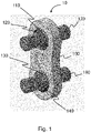
- the Fig. 1 schematically shows a fixing assembly 10 comprising a fixing shackle 100 having a substantially flat body, a first ball joint with a pin 170 and a second ball joint with a pin 180.
- a fixing shackle is commonly called a two-point shackle.
- the fixing assembly 10 is provided and configured to operate a fixing point between an aircraft engine and an aircraft engine pylon integral with the structure of the aircraft.
- the pin 170 is intended to be inserted through through holes of a fitting of the engine mast or more precisely through holes arranged in the sides of an engine mast attachment yoke
- the pin 180 is for be inserted through through-holes of an aircraft engine mounting fitting, or more precisely through-holes arranged in the sides of a mounting yoke integral with this engine.
- Fixing assemblies such as the one represented here are used to operate fixing points in a so-called “front” part of an aircraft engine, or even in a so-called “rear” part of such an engine.
- the front part of an aircraft engine means a part of the engine located on the side towards which the aircraft is moving in flight
- the rear part of an aircraft engine means a part of the engine located on the side opposite to that towards which the aircraft is moving in flight, that is to say on the side from which the aircraft is coming.
- the front part of an engine generally consists of the fan and compressor stages of a turbomachine and the rear part of an engine generally consists of the turbine stages of the turbomachine.
- the ball joint between the body of the shackle 100 and the fixing pin 170 is achieved by means of a ring 110 called the inner ring, of generally spherical shape, arranged in a through-cavity having a surface of complementary shape to the surface of the zone spherical of the ring 110.
- the ring 110 comprises a bore in which is inserted a sleeve 120 intended to receive the pin 170.
- the ball joint between the body of the shackle 100 and the fixing pin 180 is made thanks to a ring 130 also called the inner ring, of generally spherical shape, arranged in a through cavity having a surface of shape complementary to the surface of the spherical zone of the ring 130.
- the ring 130 comprises a bore in which is inserted a sleeve 140 intended to receive the pin 180.
- the rings 110 and 130 therefore have spherical zones intended to be in contact with the surfaces of the through cavities, of complementary shapes, in which they are respectively inserted.
- the rings 110 and 130 thus arranged, are free to rotate in their housings and are configured to operate ball joints.
- antifriction coatings are used for the ball joints described, as well as between the pin 170 and the sleeve 120 and between the pin 180 and the sleeve 130.
- anti-friction coatings make it possible to produce a lubrication and hardness adaptation interface interposed for example between two titanium or titanium alloy parts operating relative movements between them.
- the attachment points of the rear parts of the engines are subjected to greater temperature stresses due to the high temperatures produced by the operation of the engines and certain characteristics of such an attachment assembly may vary, depending on whether this attachment assembly is intended to operate a connection at a front point (of a front part) or at a rear point (of a rear part) of an aircraft engine.
- the body of the shackle 100, the rings 110 and 130 as well as the sleeves 120 and 140 are preferably made of titanium (Ta6V or another variant of titanium alloy) in the case of use for make a fixing point at the front of the engine; this is a mode of use called a "cold shackle", and these same elements are preferably made of Inconel 718 (or another variant of steel alloy), in the case of use for operate a fixing point at the rear of the engine; and this is a mode of use called a "hot shackle".
- the characteristics of the antifriction coatings used can vary in the presence of a mode of use called "cold shackle", at the front of an engine, or "hot shackle", at the rear of an engine.
- the coatings respectively affixed to the surfaces of the spherical zones of the rings 110 and 130 and to the bore of the sleeves have a thickness of between 50 ⁇ m and 300 ⁇ m, preferably 100 ⁇ m, and the coatings respectively affixed to the surfaces bores in the body of the shackle 100, of a shape complementary to the shapes of the surfaces of the spherical zones of the rings 110 and 130 and on the external surfaces of the pins 170 and 180, have a thickness of between 0.2 ⁇ m and 50 ⁇ m, preferably 5 ⁇ m.
- the Fig. 2 is a front view illustrating the fixing shackle 100 and defining a section plane AA with respect to the body of the shackle as well as to the ring 110 and to the sleeve 120, configured to jointly operate a ball joint with the axis 170 (not shown on the Fig.2 ).
- Section plane AA is used for illustrations related to the Fig. 3 , Fig. 4 and Fig. 5 described below.
- the Fig.3 is a partial section of the fixing shackle 100 along section plane AA illustrating the ball joint between the body of the shackle 100 and the pin 170 operated by the arrangement of the ring 110 and the sleeve 120.
- the sleeve 120 is inserted into a bore of the ring 110, which has the overall outer shape of a ball housed in a spherical cavity of the body of the shackle 100, cavity of a shape generally complementary to the shape of the ring 110.
- the sleeve 120 comprises a bore arranged around of a longitudinal axis 123, bore configured to receive the axis 170.
- the Fig. 4 represents in a magnified way the window of the Fig.3 to more clearly illustrate implementation details.
- the surface of the spherical zone of the ring 110 bears a so-called "thick" coating 111, with a thickness of the order of 100 ⁇ m (including between 50 ⁇ m and 300 ⁇ m), and made of a Copper Nickel Indium alloy of the Cu36Ni5In type for use of the shackle 100 at a front attachment point of an engine or made of a Cobalt alloy for use of the shackle at a rear engine mounting point.
- the surface of the shackle body 100 carries a so-called "thin” coating 101, with a thickness of the order of 5 ⁇ m (between 0.2 ⁇ m and 50 ⁇ m), and made of WC:CH nanocomposite material, for a front attachment point shackle for a so-called “cold shackle” application or made by treatment in the mass (low pressure carburizing) of the body of the shackle for a rear attachment point shackle for a so-called "hot shackle” application.
- a rim 112 forms a projection and curb with respect to the surface of the spherical zone of the ring 110 to encapsulate the thick coating 111 affixed to the surface of the spherical zone of the ring 110, thus preventing the edge of the coating 111 from may flake or peel, gradually disintegrating over an ever larger surface.
- the rim 112 forming a projection and a curb on the surface of the spherical zone of the ring 110 is circumferential, that is to say that it has an edge over the entire perimeter of the free end edge of the ring 110.
- the projection of the rim 112 makes it possible to form both a bowl whose bottom is coated with the coating 111 as well as a lateral protective stop for the covering 111.
- the inner surface of the sleeve 120 carries a so-called "thick" coating 121, of a thickness of the order of 100 ⁇ m (between 50 ⁇ m and 300 ⁇ m) and produced in a Copper Nickel Indium alloy of the Cu36Ni5In type or in a Copper Aluminum Fe alloy of the CuAlFe type for use of the shackle at one fixing point front of an engine or in Cobalt alloy for use of the shackle at an aft attachment point of an engine.
- a so-called "thick" coating 121 of a thickness of the order of 100 ⁇ m (between 50 ⁇ m and 300 ⁇ m) and produced in a Copper Nickel Indium alloy of the Cu36Ni5In type or in a Copper Aluminum Fe alloy of the CuAlFe type for use of the shackle at one fixing point front of an engine or in Cobalt alloy for use of the shackle at an aft attachment point of an engine.
- a rim 122 forms a projection and curb to encapsulate the thick coating 121 affixed to the surface of the bore of the sleeve 120, including in an area 120a where the diameter of the bore increases towards the end of the sleeve 120 and having a flared shape up to the edge 122.
- this prevents the edge of the coating 121 from flaking or peeling and then gradually disintegrating over an ever larger surface.
- the rim 122 forming a projection and a sidewalk on the surface of the bore of the sleeve 120 is circumferential, that is to say it has an edge over the entire perimeter of the free extremal edge of the bore.
- the projection of the rim 122 makes it possible to form both a bowl whose bottom is coated with the coating 121 as well as a lateral protective stop for the coating 121.
- Pin 170 engaged in sleeve 120 carries a so-called “thin” coating 171.
- the Fig. 4 illustrates the arrangement of the elements between them and the location of the coatings on only one side of the ring 110, or in other words at only one end of the sleeve 120.
- the arrangement described is the same on the other side of the ring 110, that is to say at the other end of the sleeve 120, so that there are therefore two edges 112 and two edges 122 respectively machined on the ring 110 and on the bore of the sleeve 120
- the sleeve 120 is not completely similar at its two ends since it comprises a shoulder 120' on the side of the bore of the ring 110 by which it is inserted into the latter.
- the flared shape of the bore of the sleeve 120 is present on both sides of the sleeve 120 to simplify the insertion of the pin 170 by facilitating its guiding and preventing any risk of damage to the coatings during insertion, parallel to the longitudinal axis of the bore of the sleeve 120.
- the dimensions of the elements represented in the figures do not correspond to a reference scale and characteristics are represented in an oversized way to facilitate the readability of the description of the embodiments.
- the height of the edges 112 and 122 is deliberately exaggerated in the figures, as is the flared shape of the ends of the inner surface of the sleeve 120, in other words the bore of the sleeve 120.
- the Fig. 5 illustrates all of the elements making up the ball joint between the body of the shackle 100 and the pin 170, namely the ring 110 in which the sleeve 120 is inserted having a bore whose ends are flared, made around an axis 123.
- the surfaces carrying the thick coatings 111 and 121 are respectively bordered by the flanges 112 and 122.
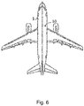
- the Fig. 6 illustrates an aircraft 1 comprising at least the shackle 100 or an engine attachment shackle similar to the shackle 100, which advantageously makes it possible to increase the longevity of the engine attachments.
- the invention is not limited to the embodiments and examples described above, but more generally relates to any mechanical part, such as a shackle for attaching an aircraft engine for example, comprising an anti-friction coating affixed to an area bordered by a rim for the purpose of encapsulating this coating and limiting the risks of abrasion, peeling, detachment or premature disintegration of this coating.
- a shackle for attaching a motor according to the invention can be configured to comprise more than two attachment points to an axis, for example three attachment points to an axis.
- the surface of the spherical zone of the ring of a ball joint as described bears an antifriction coating bordered by a protective rim and the surface of the bore of the sleeve of the same ball joint does not bear anti-friction coating or has an anti-friction coating that is not edged with a protective edge.
- the surface of the bore of a sleeve of a ball joint as described bears an antifriction coating bordered by a protective rim and the surface of the spherical zone of the ring of the same ball joint does not wears no anti-friction covering or wears an anti-friction covering which is not bordered by a protective edge.
Landscapes
- Engineering & Computer Science (AREA)
- General Engineering & Computer Science (AREA)
- Mechanical Engineering (AREA)
- Aviation & Aerospace Engineering (AREA)
- Chemical & Material Sciences (AREA)
- Chemical Kinetics & Catalysis (AREA)
- Materials Engineering (AREA)
- Metallurgy (AREA)
- Organic Chemistry (AREA)
- Ceramic Engineering (AREA)
- Pivots And Pivotal Connections (AREA)
- Snaps, Bayonet Connections, Set Pins, And Snap Rings (AREA)
Abstract
Description
- La présente invention concerne une manille de fixation pour opérer une liaison entre un moteur d'aéronef et un mât moteur. L'invention concerne plus particulièrement un agencement de revêtements antifriction sur une liaison rotule d'une telle manille, ainsi qu'un aéronef comprenant une telle manille.
- Des manilles de fixation à deux points ou trois points, encore parfois appelées bielles ou biellettes sont couramment utilisées pour la fixation des moteurs d'aéronefs aux mâts moteurs solidaires de la structure de l'aéronef. Ces attaches moteurs participent à un système d'interface mécanique de transfert d'efforts dit « isostatique », bloquant selon six degrés de liberté, et permettant d'assurer un montage non contraint tout en répondant à des exigences de certification et de sécurité. Les systèmes d'interface mécanique entre un moteur et un mât moteur ont la particularité d'être soumis à des températures importantes, eu égard à la proximité du moteur, notamment pour ce qui concerne les attaches moteurs dites arrière. Des phénomènes de vieillissement prématuré surviennent, notamment du fait des nombreux cycles thermomécaniques que subissent ces éléments des aéronefs. Des techniques de fixation récentes permettent de réaliser des opérations rapides de montage et de démontage de moteurs d'aéronef en utilisant des manilles de fixation moteur dans lesquelles sont insérés des axes traversant également des chapes de ferrures agencées sur un mât moteur ou sur un moteur. Ces manilles de fixation moteur utilisent des revêtements antifriction pour limiter l'usure de surfaces de contact entre des éléments de liaison et améliorer les caractéristiques de l'interface de liaison. Il arrive malheureusement que ces revêtements se dégradent ou s'écaillent progressivement, principalement sur leurs bords ou à partir de leurs bords, entraînant alors un phénomène d'arrachement ou de pelage (ou délaminage) préjudiciable à la qualité des liaisons mécaniques opérées. Ces phénomènes induisent un besoin de changement des pièces de liaison portant les revêtements.
- La situation peut donc être améliorée.
- La présente invention vise notamment à créer un encapsulage des revêtements antifriction de surface des éléments de liaison d'une manille de fixation d'un moteur d'aéronef et de permettre de préserver ainsi ces revêtements d'une usure prématurée.
- A cet effet, l'invention a pour objet une manille pour la fixation d'un moteur d'aéronef à un mât solidaire de la structure de l'aéronef, par l'intermédiaire d'au moins un axe, la manille comprenant un corps et un point de fixation audit axe par l'intermédiaire d'une liaison rotule, la liaison rotule comprenant une bague présentant une zone extérieure sphérique et un premier alésage, la bague étant assemblée dans une cavité du corps de la manille présentant une forme complémentaire à ladite zone extérieure sphérique,
la manille présentant en outre les caractéristiques : - la liaison rotule comprend un manchon assemblé dans le premier alésage et présentant un deuxième alésage configuré pour recevoir ledit axe et dont le diamètre s'accroît progressivement pour présenter une surface intérieure évasée à chacune de ses extrémités,
- la surface extérieure sphérique de la bague porte un premier revêtement antifriction réalisé sur une première zone s'étendant au-delà de sa zone de contact avec le corps de la manille et ladite première zone est bordée par des premiers rebords formant saillie par rapport à la surface extérieure sphérique de la bague, autour du premier revêtement, de sorte à former une butée de protection autour du premier revêtement et à l'encapsuler, et/ou
- le deuxième alésage, du manchon, porte un deuxième revêtement antifriction, sur une deuxième zone s'étendant au-delà de sa zone de contact avec ledit axe et ladite deuxième zone est bordée par des deuxièmes rebords formant saillie par rapport à la surface du deuxième alésage, autour du deuxième revêtement antifriction, aux extrémités de la surface intérieure évasée du manchon.
- Avantageusement, il est ainsi possible de protéger par une bordure formant saillie et trottoir les bords des revêtements antifriction apposés sur les surfaces d'éléments de liaison mécanique et d'accroître conséquemment la longévité des revêtements en évitant ou en réduisant conséquemment des phénomènes de pelage et de désagrégation. Cela permet en conséquence de réduire les opérations de maintenance ainsi que les coûts y afférents. Il apparaît en outre plus facile de revêtir à nouveau les surfaces concernées en cas d'usure des revêtements.
- La manille de fixation selon l'invention peut également comporter les caractéristiques suivantes, considérées seules ou en combinaison :
- Les premiers et deuxièmes rebords présentent une hauteur supérieure ou égale à 0.1 mm.
- La surface de la cavité du corps de la manille présentant une forme complémentaire à ladite zone extérieure sphérique de la bague porte un troisième revêtement antifriction. Cela accroît avantageusement les qualités de l'interface de liaison entre la surface de la zone sphérique de la bague et la surface de la cavité du corps de la manille dans laquelle est logée la bague.
- Le premier revêtement antifriction est réalisé dans un alliage Cuivre Nickel Indium de type Cu36Ni5In ou dans un alliage de Cobalt et présente une épaisseur comprise en 50 µm et 300 µm, préférentiellement 100 µm.
- Le deuxième revêtement antifriction est réalisé dans un alliage Cuivre Nickel Indium de type Cu36Ni5In, dans un alliage Cuivre Aluminium Fe de type CuAlFe, ou dans un alliage de Cobalt et présente une épaisseur comprise en 50 µm et 300 µm, préférentiellement 100 µm.
- Le troisième revêtement antifriction est réalisé par traitement dans la masse ou en matériau nanocomposite de type WC:C-H et présente une épaisseur comprise en 0,2 µm et 50 µm, préférentiellement 5 µm.
- Le corps de la manille, la bague et le manchon sont réalisés dans un même matériau choisi parmi : les alliages de Titane ou les alliages d'acier.
- L'invention a également pour objet un ensemble de fixation comprenant une manille telle que précédemment décrite et un axe portant sur sa surface extérieure, un quatrième revêtement antifriction réalisé en matériau nanocomposite de type WC :C-H ou WcCo et présentant une épaisseur comprise en 0,2 µm et 50 µm, préférentiellement 5 µm.
- Selon un mode de réalisation, l'axe de l'ensemble de fixation est réalisé dans un matériau choisi parmi : les alliages de Titane ou les alliages d'acier.
- L'invention a également pour objet un aéronef comprenant une manille telle que précédemment décrite ou un ensemble de fixation tel que précité.
- Les caractéristiques de l'invention mentionnées ci-dessus, ainsi que d'autres, apparaîtront plus clairement à la lecture de la description suivante d'au moins un exemple de réalisation, ladite description étant faite en relation avec les dessins joints, parmi lesquels :
- [
Fig. 1 ] illustre, schématiquement et en perspective, un ensemble de fixation d'un moteur d'aéronef à un mât moteur solidaire de la structure d'un aéronef, selon un mode de réalisation ; - [
Fig. 2 ] illustre, en plan de face, l'ensemble de fixation déjà représenté en perspective sur laFig. 1 en définissant un plan de coupe A-A utile à une description subséquente de modes de réalisation ; - [
Fig. 3 ] est une coupe partielle d'une liaison rotule de l'ensemble de fixation déjà représenté sur lesFig. 1 etFig. 2 , selon la coupe A-A de laFig. 2 ; - [
Fig. 4 ] illustre schématiquement et de façon agrandie des détails d'implémentation d'éléments représentés sur laFig. 3 ; - [
Fig. 5 ] illustre schématiquement une liaison rotule d'une manille de fixation d'un moteur d'aéronef; et, - [
Fig. 6 ] représente, en vue de dessus, un aéronef comprenant une manille de fixation d'un moteur d'aéronef selon un mode de réalisation. - La
Fig. 1 représente schématiquement un ensemble de fixation 10 comprenant une manille de fixation 100 présentant un corps sensiblement plat, une première liaison rotule avec un axe 170 et une seconde liaison rotule avec un axe 180. Une telle manille de fixation est communément appelée manille deux-points. Il est à noter que l'invention décrite ici peut s'appliquer à tout élément de liaison comprenant au moins une liaison rotule et ne se limite pas au cas d'une manille. L'ensemble de fixation 10 est prévu et configuré pour opérer un point de fixation entre un moteur d'aéronef et un mât de moteur d'aéronef solidaire de la structure de l'aéronef. Ainsi, par exemple, l'axe 170 est destiné à être inséré à travers des trous traversants d'une ferrure du mât moteur ou plus précisément des trous traversants agencés dans des flancs d'une chappe de fixation du mât moteur, et l'axe 180 est destiné à être inséré à travers des trous traversants d'une ferrure de fixation du moteur d'aéronef, ou plus précisément des trous traversants agencés dans des flancs d'une chappe de fixation solidaire de ce moteur. Des ensembles de fixation tels que celui représenté ici sont utilisés pour opérer des points de fixation dans une partie dite « avant » d'un moteur d'aéronef, ou encore dans une partie dite « arrière » d'un tel moteur. On entend ici par partie avant d'un moteur d'aéronef une partie du moteur située du côté vers lequel l'aéronef évolue en vol, et on entend par partie arrière d'un moteur d'aéronef, une partie du moteur située du côté opposé à celui vers lequel évolue l'aéronef en vol, c'est-à-dire du côté d'où vient l'aéronef. - La partie avant d'un moteur est généralement constituée des étages de soufflante et de compresseur d'une turbomachine et la partie arrière d'un moteur est généralement constituée des étages de turbines de la turbomachine.
- La liaison rotule entre le corps de la manille 100 et l'axe de fixation 170 est réalisée grâce à une bague 110 dite bague intérieure, de forme globalement sphérique, agencée dans une cavité traversante présentant une surface de forme complémentaire à la surface de la zone sphérique de la bague 110. La bague 110 comprend un alésage dans lequel est inséré un manchon 120 destiné à recevoir l'axe 170. De façon similaire, la liaison rotule entre le corps de la manille 100 et l'axe de fixation 180 est réalisée grâce à une bague 130 dite elle aussi bague intérieure, de forme globalement sphérique, agencée dans une cavité traversante présentant une surface de forme complémentaire à la surface de la zone sphérique de la bague 130. La bague 130 comprend un alésage dans lequel est inséré un manchon 140 destiné à recevoir l'axe 180.
- Les bagues 110 et 130 présentent donc des zones sphériques destinées à être en contact avec les surfaces des cavités traversantes, de formes complémentaires, dans lesquelles elles sont respectivement insérées. Les bagues 110 et 130, ainsi agencées, sont libres en rotation dans leurs logements et sont configurées pour opérer des liaisons rotules.
- Avantageusement, des revêtements antifriction sont utilisés pour les liaisons rotules décrites, ainsi qu'entre l'axe 170 et le manchon 120 et entre l'axe 180 et le manchon 130.
- En effet, de tels revêtements antifriction permettent de réaliser une interface d'adaptation de lubrification et de dureté interposée par exemple entre deux pièces en Titane ou en alliage de Titane opérant entre elles des mouvements relatifs.
- Une telle interface comporte le plus souvent deux revêtements formant des couches d'adaptation, parmi lesquelles :
- une première couche d'adaptation est déposée sur la première pièce et a une dureté inférieure à celle de la première pièce, cette première couche comporte une morphologie microporeuse, lui conférant une fonction d'adaptation de lubrification en retenant la graisse d'un lubrifiant liquide dans des micropores,
- une deuxième couche d'adaptation coopérant avec la première couche et déposée sur la deuxième pièce, cette deuxième couche comporte une dureté supérieure à celle de la première couche et comporte de plus une fonction d'adaptation de lubrification en libérant des lubrifiants solides sous l'effet de frottement avec la première pièce.
- Classiquement, les points de fixation des parties arrière des moteurs sont soumis à des contraintes de températures plus importantes du fait des températures élevées produites par le fonctionnement des moteurs et certaines caractéristiques d'un tel ensemble de fixation peuvent varier, selon que cet ensemble de fixation est destiné à opérer une liaison en un point avant (d'une partie avant) ou en un point arrière (d'une partie arrière) d'un moteur d'aéronef.
- Ainsi, par exemple, le corps de la manille 100, les bagues 110 et 130 ainsi que les manchons 120 et 140 sont préférentiellement réalisés en Titane (Ta6V ou dans une autre variante d'alliage de Titane) dans le cas d'une utilisation pour opérer un point de fixation à l'avant du moteur ; c'est là un mode d'utilisation dit d'une « manille froide », et ces mêmes éléments sont préférentiellement réalisés en Inconel 718 (ou dans une autre variante d'alliage d'acier), dans le cas d'une utilisation pour opérer un point de fixation à l'arrière du moteur ; et c'est là un mode d'utilisation dit d'une « manille chaude ».
- De la même façon que pour ce qui concerne les matériaux utilisés pour la fabrication du corps de la manille 100, des bagues 110 et 130 et des manchons 120 et 140, des caractéristiques des revêtements antifriction utilisés peuvent varier en présence d'un mode d'utilisation dit « manille froide », à l'avant d'un moteur, ou « manille chaude », à l'arrière d'un moteur.
- Selon un mode de réalisation, les revêtements antifriction suivants sont utilisés pour une « manille froide » agencée à l'avant d'un moteur :
- un revêtement du corps de la manille 100, apposé sur la surface présentant une forme complémentaire à la zone sphérique de la bague est réalisé en matériau nanocomposite WC :C-H,
- un revêtement apposé sur la zone sphérique de chacune des bagues 110 et 130 est réalisé dans un alliage Cuivre Nickel Indium de type Cu36Ni5In,
- un revêtement apposé sur la surface de l'alésage des manchons 120 et 140, y compris sur la partie évasée de l'alésage, est réalisé dans un alliage Cuivre Nickel Indium de type Cu36Ni5In ou dans un alliage Cuivre Aluminium Fe de type CuAlFe,
- un revêtement apposé sur chacun des axes 170 et 180 est réalisé dans un matériau nanocomposite de type WC:C-H,
- un revêtement du corps de la manille 100, apposé sur la surface présentant une forme complémentaire à la zone sphérique de la bague est réalisé par traitement dans la masse du corps de la manille 100, le traitement dans la masse étant une cémentation basse pression,
- un revêtement apposé sur la zone sphérique de chacune des bagues 110 et 130 est réalisé dans un alliage de Cobalt,
- un revêtement apposé sur la surface de l'alésage des manchons 120 et 140, y compris sur la partie évasée de l'alésage, est réalisé dans un alliage de Cobalt,
- un revêtement apposé sur chacun des axes 170 et 180 est réalisé dans un matériau nanocomposite de type WcCo.
- Selon un mode de réalisation, les revêtements respectivement apposés sur les surfaces des zones sphériques des bagues 110 et 130 et sur l'alésage des manchons présentent une épaisseur comprise entre 50 µm et 300 µm, préférentiellement 100 µm et les revêtements respectivement apposés sur les surfaces des alésages du corps de la manille 100, de forme complémentaire aux formes des surfaces des zones sphériques des bagues 110 et 130 et sur les surfaces externes des axes 170 et 180, présentent une épaisseur comprise en 0,2 µm et 50 µm, préférentiellement 5 µm.
- La
Fig. 2 est une vue de face illustrant la manille de fixation 100 et définissant un plan de coupe A-A par rapport au corps de la manille ainsi qu'à la bague 110 et au manchon 120, configurés pour opérer conjointement une liaison rotule avec l'axe 170 (non représenté sur laFig.2 ). Le plan de coupe A-A est utilisé pour des illustrations en rapport avec lesFig. 3 ,Fig. 4 etFig. 5 décrites ci-après. - La
Fig.3 est une coupe partielle de la manille de fixation 100 selon le plan de coupe A-A illustrant la liaison rotule entre le corps de la manille 100 et l'axe 170 opérée par l'agencement de la bague 110 et du manchon 120. Le manchon 120 est inséré dans un alésage de la bague 110, laquelle présente une forme globale extérieure de bille logée dans une cavité sphérique du corps de la manille 100, cavité de forme globalement complémentaire à la forme de la bague 110. Le manchon 120 comprend un alésage agencé autour d'un axe longitudinal 123, alésage configuré pour recevoir l'axe 170. Il existe donc des surfaces de contact entre la zone sphérique de la bague 110 et le corps de la manille 100 d'une part, et entre la surface intérieure du manchon 120 et l'axe 170, d'autre part. L'agencement de la liaison rotule opérée par la bague 130 et le manchon 140 n'est pas représenté ici puisqu'il est similaire à celui de la bague 110 et du manchon 120. Une fenêtre rectangulaire 150 de laFig.3 apparaît agrandie sur laFig. 4 aux fins de mieux décrire certains détails d'implémentation. - La
Fig. 4 représente de façon agrandie la fenêtre de laFig.3 pour illustrer plus lisiblement des détails d'implémentation. - S'agissant de la liaison entre la bague 110 et le corps de la manille 100, la surface de la zone sphérique de la bague 110 porte un revêtement 111 dit « épais », d'une épaisseur de l'ordre de 100 µm (comprise entre 50 µm et 300 µm), et réalisé dans un alliage Cuivre Nickel Indium de type Cu36Ni5In pour une utilisation de la manille 100 à un point de fixation avant d'un moteur ou réalisé dans un alliage de Cobalt pour une utilisation de la manille à un point de fixation arrière d'un moteur. La surface du corps de manille 100, de forme complémentaire à la surface de la zone sphérique de la bague 110, porte un revêtement 101, dit « fin », d'une épaisseur de l'ordre de 5 µm (comprise entre 0,2 µm et 50 µm), et réalisé en matériau nanocomposite WC :C-H, pour une manille de point de fixation avant pour une application dite « manille froide » ou réalisé par traitement dans la masse (cémentation basse pression) du corps de la manille pour une manille de point de fixation arrière pour une application dite « manille chaude ». Astucieusement, un rebord 112 forme saillie et trottoir par rapport à la surface de la zone sphérique de la bague 110 pour encapsuler le revêtement épais 111 apposé sur la surface de la zone sphérique de la bague 110, évitant ainsi que le bord du revêtement 111 ne puisse s'écailler ou peler en se désagrégeant alors progressivement sur une surface toujours plus importante. Avantageusement, le rebord 112 formant saillie et trottoir sur la surface de la zone sphérique de la bague 110 est circonférentiel, c'est-à-dire qu'il présente une arête sur tout le périmètre du bord extrémal libre de la bague 110. Avantageusement, la saillie du rebord 112 permet de former à la fois une cuvette dont le fond est revêtu du revêtement 111 ainsi qu'une butée de protection latérale du revêtement 111.
- S'agissant de la liaison entre le manchon 120 et l'axe 170, la surface intérieure du manchon 120, soit en d'autres termes la surface de l'alésage du manchon 120, porte un revêtement 121 dit « épais », d'une épaisseur de l'ordre de 100 µm (comprise entre 50 µm et 300 µm) et réalisé dans un alliage Cuivre Nickel Indium de type Cu36Ni5In ou dans un alliage Cuivre Aluminium Fe de type CuAlFe pour une utilisation de la manille à un point de fixation avant d'un moteur ou en alliage de Cobalt pour une utilisation de la manille à un point de fixation arrière d'un moteur. Astucieusement, un rebord 122 forme saillie et trottoir pour encapsuler le revêtement épais 121 apposé sur la surface de l'alésage du manchon 120, y compris dans une zone 120a où le diamètre de l'alésage s'accroît en allant vers l'extrémité du manchon 120 et en présentant une forme évasée jusqu'au rebord 122. Là encore, cela permet d'éviter que le bord du revêtement 121 ne puisse s'écailler ou peler et se désagréger ensuite progressivement sur une surface toujours plus importante. Avantageusement, le rebord 122 formant saillie et trottoir sur la surface de l'alésage du manchon 120 est circonférentiel, c'est-à-dire qu'il présente une arête sur tout le périmètre du bord extrémal libre de l'alésage. Avantageusement, la saillie du rebord 122 permet de former à la fois une cuvette dont le fond est revêtu du revêtement 121 ainsi qu'une butée de protection latérale du revêtement 121.
- L'axe 170 engagé dans le manchon 120 porte un revêtement 171 dit « fin ». La
Fig. 4 illustre l'agencement des éléments entre eux et la localisation des revêtements d'un côté seulement de la bague 110, ou en d'autres termes à une extrémité seulement du manchon 120. Cependant, l'agencement décrit est le même de l'autre côté de la bague 110, c'est-à-dire à l'autre extrémité du manchon 120, si bien qu'il existe donc deux bords 112 et deux bords 122 respectivement usinés sur la bague 110 et sur l'alésage du manchon 120. Il est à noter toutefois que le manchon 120 n'est pas complètement semblable à ses deux extrémités puisqu'il comprend un épaulement 120' du côté de l'alésage de la bague 110 par lequel il est inséré dans cette dernière. La forme évasée de l'alésage du manchon 120 est présente des deux côtés du manchon 120 pour simplifier l'insertion de l'axe 170 en facilitant son guidage et en prévenant tout risque d'endommagement des revêtements lors de l'insertion, parallèlement à l'axe longitudinal de l'alésage du manchon 120. Bien évidemment, les dimensions des éléments représentés sur les figures ne correspondent pas à une échelle de référence et des caractéristiques sont représentées de façon surdimensionnée pour faciliter la lisibilité de la description des modes de réalisation. Par exemple, la hauteur des bords 112 et 122 est délibérément exagérée sur les figures, tout comme l'est la forme évasée des extrémités de la surface intérieure du manchon 120, soit en d'autres termes de l'alésage du manchon 120. - La
Fig. 5 illustre l'ensemble des éléments composant la liaison rotule entre le corps de la manille 100 et l'axe 170, à savoir la bague 110 dans laquelle est inséré le manchon 120 présentant un alésage dont les extrémités sont de forme évasée, réalisé autour d'un axe 123. Les surfaces portant les revêtements épais 111 et 121 sont respectivement bordées par les rebords 112 et 122. - La
Fig. 6 illustre un aéronef 1 comprenant au moins la manille 100 ou une manille de fixation d'un moteur semblable à la manille 100, ce qui permet d'accroître avantageusement la longévité des attaches moteurs. - L'invention ne se limite pas aux seuls modes de réalisation et exemples décrits ci-avant, mais concerne plus généralement toute pièce mécanique, telle qu'une manille de fixation d'un moteur d'aéronef par exemple, comprenant un revêtement antifriction apposé sur une zone bordée par un rebord aux fins d'encapsuler ce revêtement et de limiter les risques d'abrasion, d'écaillement, de décollement ou de désagrégation prématurés de ce revêtement. En particulier, des variantes peuvent comprendre d'autres revêtements antifriction que ceux énoncés dans les exemples décrits. Selon des variantes, également une manille de fixation d'un moteur selon l'invention peut être configurée pour comprendre plus de deux points de fixation à un axe, par exemple trois points de fixation à un axe.
- Selon des variantes encore, la surface de la zone sphérique de la bague d'une liaison rotule telle que décrite porte un revêtement antifriction bordé d'un rebord de protection et la surface de l'alésage du manchon de la même liaison rotule ne porte pas de revêtement antifriction ou porte un revêtement antifriction qui n'est pas bordé d'un rebord de protection.
- Selon des variantes encore, la surface de l'alésage d'un manchon d'une liaison rotule telle que décrite porte un revêtement antifriction bordé d'un rebord de protection et la surface de la zone sphérique de la bague de la même liaison rotule ne porte pas de revêtement antifriction ou porte un revêtement antifriction qui n'est pas bordé d'un rebord de protection.
Claims (10)
- Manille (100) pour la fixation d'un moteur d'aéronef (1) à un mât solidaire de la structure de l'aéronef (1), par l'intermédiaire d'au moins un axe (170), la manille (100) comprenant un corps et un point de fixation audit axe (170) par l'intermédiaire d'une liaison rotule, la liaison rotule comprenant une bague (110) présentant une zone extérieure sphérique et un premier alésage, la bague (110) étant assemblée dans une cavité du corps de la manille (100) présentant une forme complémentaire à ladite zone extérieure sphérique,
la manille (100) étant caractérisée en ce que :- la liaison rotule comprend un manchon (120) assemblé dans le premier alésage et présentant un deuxième alésage configuré pour recevoir ledit axe (170) et dont le diamètre s'accroît progressivement pour présenter une surface intérieure évasée à chacune de ses extrémités,- la surface extérieure sphérique de la bague (110) porte un premier revêtement (111) antifriction réalisé sur une première zone s'étendant au-delà de sa zone de contact avec le corps de la manille (100) et ladite première zone de la bague (110) est bordée par des premiers rebords (112) formant saillie par rapport à la surface extérieure sphérique de la bague (110), autour du premier revêtement (111), de sorte à former une butée de protection du premier revêtement et à l'encapsuler, et/ou- le deuxième alésage du manchon (120) porte un deuxième revêtement (121) antifriction, sur une deuxième zone s'étendant au-delà de sa zone de contact avec ledit axe (170) et ladite deuxième zone est bordée par des deuxièmes rebords (122) formant saillie par rapport à la surface du deuxième alésage, autour du deuxième revêtement (121), aux extrémités de la surface intérieure évasée de l'alésage du manchon (120), de sorte à former une butée de protection du deuxième revêtement et à l'encapsuler. - Manille (100) pour la fixation d'un moteur d'aéronef selon la revendication 1, dans laquelle lesdits premiers (112) et deuxièmes (122) rebords présentent une hauteur supérieure ou égale à 0,1 mm.
- Manille (100) pour la fixation d'un moteur d'aéronef selon l'une des revendications 1 et 2, dans laquelle la surface de la cavité du corps de la manille présentant une forme complémentaire à ladite zone extérieure sphérique de la bague porte un troisième revêtement (101) antifriction.
- Manille (100) selon l'une quelconque des revendications 1 à 3, dans laquelle le premier revêtement (111) antifriction est réalisé dans un alliage Cuivre Nickel Indium de type Cu36Ni5In ou dans un alliage de Cobalt et présente une épaisseur comprise en 50 µm et 300 µm.
- Manille (100) selon l'une quelconque des revendications 1 à 4, dans laquelle le deuxième revêtement (121) antifriction est réalisé dans un alliage Cuivre Nickel Indium de type Cu36Ni5In, dans un alliage Cuivre Aluminium Fe de type CuAlFe, ou dans un alliage de Cobalt et présente une épaisseur comprise entre 50 µm et 300 µm.
- Manille (100) selon la revendication 3, dans laquelle le troisième revêtement (101) antifriction est réalisé par traitement dans la masse ou en matériau nanocomposite de type WC:C-H et présente une épaisseur comprise en 0,2 µm et 50 µm.
- Manille (100) selon l'une quelconque des revendications 1 à 6, dans laquelle le corps, la bague et le manchon sont réalisés dans un même matériau choisi parmi : les alliages de Titanes ou les alliages d'acier.
- Ensemble de fixation (10) comprenant une manille (100) selon l'une des revendications 1 à 7, et un axe (170) portant sur sa surface externe un quatrième revêtement (171) antifriction réalisé dans un matériau nanocomposite de type WC:C-H ou WcCo et présentant une épaisseur comprise en 0,2 µm et 50 µm.
- Ensemble de fixation (10) selon la revendication précédente, dans lequel l'axe (170) est réalisé dans un matériau choisi parmi : les alliages de Titane ou les alliages d'acier.
- Aéronef (1) comprenant une manille (100) selon l'une des revendications 1 à 6, ou un ensemble de fixation (10) selon l'une des revendications 7 et 8.
Applications Claiming Priority (1)
| Application Number | Priority Date | Filing Date | Title |
|---|---|---|---|
| FR2107055A FR3124164A1 (fr) | 2021-06-30 | 2021-06-30 | Manille de fixation d’un moteur d’aeronef comprenant un couple de revetements antifriction encapsules, et aeronef comprenant une telle manille. |
Publications (2)
| Publication Number | Publication Date |
|---|---|
| EP4112952A1 true EP4112952A1 (fr) | 2023-01-04 |
| EP4112952B1 EP4112952B1 (fr) | 2024-01-03 |
Family
ID=77226923
Family Applications (1)
| Application Number | Title | Priority Date | Filing Date |
|---|---|---|---|
| EP22181436.1A Active EP4112952B1 (fr) | 2021-06-30 | 2022-06-28 | Manille de fixation d'un moteur d' aéronef comprenant un couple de revêtements antifriction encapsules, et aéronef comprenant une telle manille |
Country Status (4)
| Country | Link |
|---|---|
| US (1) | US11952135B2 (fr) |
| EP (1) | EP4112952B1 (fr) |
| CN (1) | CN115535262A (fr) |
| FR (1) | FR3124164A1 (fr) |
Cited By (1)
| Publication number | Priority date | Publication date | Assignee | Title |
|---|---|---|---|---|
| FR3147253A1 (fr) * | 2023-03-29 | 2024-10-04 | Airbus Operations (S.A.S.) | Procédé d’installation d’un système de fixation d’une structure d’une aile à une structure d’un mât d’aéronef |
Families Citing this family (1)
| Publication number | Priority date | Publication date | Assignee | Title |
|---|---|---|---|---|
| FR3150504A1 (fr) * | 2023-06-28 | 2025-01-03 | Airbus Operations | Système d’attache moteur avant pour un moteur d’aéronef qui comporte une structure compacte |
Citations (5)
| Publication number | Priority date | Publication date | Assignee | Title |
|---|---|---|---|---|
| EP0614722A1 (fr) * | 1993-03-11 | 1994-09-14 | Sarma | Procédé de revêtement dur d'une rotule et rotule mise en oeuvre par ce procédé |
| FR2887853A1 (fr) * | 2005-06-29 | 2007-01-05 | Airbus France Sas | Attache moteur pour aeronef destinee a etre interposee entre un moteur et un mat d'accrochage |
| EP2048389A2 (fr) * | 2007-10-09 | 2009-04-15 | SKF Aerospace France | Rotule légère d'articulation et procédé de fabrication d'une telle rotule |
| EP2963304A1 (fr) * | 2014-07-01 | 2016-01-06 | SKF Aerospace France | Palier lisse sphérique avec manchon interne |
| EP3159084A1 (fr) * | 2015-10-20 | 2017-04-26 | SKF Aerospace France | Anneau pour un palier lisse et dispositif de fixation comprenant cet anneau |
Family Cites Families (6)
| Publication number | Priority date | Publication date | Assignee | Title |
|---|---|---|---|---|
| US5860623A (en) * | 1995-05-03 | 1999-01-19 | The Boeing Company | Three link failsafe engine mount |
| DE102006043930B4 (de) * | 2006-09-14 | 2009-08-13 | Zf Friedrichshafen Ag | Kugelgelenk |
| US20110142532A1 (en) * | 2009-07-24 | 2011-06-16 | Roller Bearing Company Of America, Inc. | Strut for exhaust nozzle and method of manufacture |
| US8851417B2 (en) * | 2012-08-07 | 2014-10-07 | United Technologies Corporation | Self-retaining shear pin for blind mount location |
| US9951808B2 (en) * | 2013-11-15 | 2018-04-24 | Bell Helicopter Textron Inc. | Elastomeric spherical bearing assembly and structural member incorporating the same |
| FR3027875A1 (fr) * | 2014-10-30 | 2016-05-06 | Airbus Operations Sas | Dispositif de fixation d'un moteur d'aeronef, et aeronef correspondant |
-
2021
- 2021-06-30 FR FR2107055A patent/FR3124164A1/fr active Pending
-
2022
- 2022-06-28 EP EP22181436.1A patent/EP4112952B1/fr active Active
- 2022-06-28 US US17/851,407 patent/US11952135B2/en active Active
- 2022-06-30 CN CN202210767434.9A patent/CN115535262A/zh active Pending
Patent Citations (5)
| Publication number | Priority date | Publication date | Assignee | Title |
|---|---|---|---|---|
| EP0614722A1 (fr) * | 1993-03-11 | 1994-09-14 | Sarma | Procédé de revêtement dur d'une rotule et rotule mise en oeuvre par ce procédé |
| FR2887853A1 (fr) * | 2005-06-29 | 2007-01-05 | Airbus France Sas | Attache moteur pour aeronef destinee a etre interposee entre un moteur et un mat d'accrochage |
| EP2048389A2 (fr) * | 2007-10-09 | 2009-04-15 | SKF Aerospace France | Rotule légère d'articulation et procédé de fabrication d'une telle rotule |
| EP2963304A1 (fr) * | 2014-07-01 | 2016-01-06 | SKF Aerospace France | Palier lisse sphérique avec manchon interne |
| EP3159084A1 (fr) * | 2015-10-20 | 2017-04-26 | SKF Aerospace France | Anneau pour un palier lisse et dispositif de fixation comprenant cet anneau |
Cited By (1)
| Publication number | Priority date | Publication date | Assignee | Title |
|---|---|---|---|---|
| FR3147253A1 (fr) * | 2023-03-29 | 2024-10-04 | Airbus Operations (S.A.S.) | Procédé d’installation d’un système de fixation d’une structure d’une aile à une structure d’un mât d’aéronef |
Also Published As
| Publication number | Publication date |
|---|---|
| US20230002067A1 (en) | 2023-01-05 |
| EP4112952B1 (fr) | 2024-01-03 |
| US11952135B2 (en) | 2024-04-09 |
| FR3124164A1 (fr) | 2022-12-23 |
| CN115535262A (zh) | 2022-12-30 |
Similar Documents
| Publication | Publication Date | Title |
|---|---|---|
| EP2014873B1 (fr) | Clinquant pour aube de turbomachine | |
| EP4112952B1 (fr) | Manille de fixation d'un moteur d' aéronef comprenant un couple de revêtements antifriction encapsules, et aéronef comprenant une telle manille | |
| FR2941487A1 (fr) | Aube de turbomachine en materiau composite a pied renforce | |
| CA2802821C (fr) | Secteur angulaire de redresseur pour compresseur de turbomachine | |
| EP2657558B1 (fr) | Moyen d'accouplement flexible, et transmission mécanique | |
| FR2831207A1 (fr) | Plates-formes pour aubes d'un ensemble rotatif | |
| EP2870323A1 (fr) | Dispositif de joint d'etancheite de palier de turbomachine avec deux joints elastiques | |
| FR2820402A1 (fr) | Dispositif d'accrochage d'un moteur sur un aeronef | |
| FR2963383A1 (fr) | Aube de turbomachine, rotor, turbine basse pression et turbomachine equipes d'une telle aube | |
| EP3180528B1 (fr) | Assemblage de type liaison pivot | |
| FR3082555A1 (fr) | Roue d'aubes redresseuses d'un moteur d'aeronef, tel qu'un turboreacteur | |
| FR3131598A1 (fr) | Turbine pour turbomachine | |
| EP3243670B1 (fr) | Roue d'aeronef | |
| FR3127933A1 (fr) | Piece d’attache pour un ensemble propulsif d’aeronef | |
| FR2946400A1 (fr) | Disque de rotor, en particulier de soufflante, pour turbomachine | |
| EP3037684B1 (fr) | Chape avec empochement et/ou relief | |
| BE1032906B1 (fr) | Ensemble vissé et précontraint présentant une conception améliorée à des fins de maintien des performances sous températures cryogéniques | |
| EP3475581B1 (fr) | Anneau de carénage de moyeu de roue à aubes de turbine à gaz, ledit anneau étant plastiquement déformable | |
| FR2931870A1 (fr) | Equilibrage d'une piece tournante dans une turbomachine. | |
| FR3154140A1 (fr) | Disque de rotor pour une turbomachine d’aeronef | |
| WO2022112685A1 (fr) | Carter comprenant des raidisseurs internes et/ou externes | |
| EP3991883A1 (fr) | Procédé de fabrication d'une aube pour turbomachine | |
| FR3154445A1 (fr) | Dispositif comprenant un palier à support frangible et encombrement limité | |
| FR3141440A1 (fr) | Dispositif de suspension d’un équipement pour turbomachine à une structure moteur de turbomachine | |
| FR2933129A1 (fr) | Carter de turbomachine a la tenue mecanique amelioree, turbine comprenant un tel carter et moteur d'aeronef equipe d'une telle turbine |
Legal Events
| Date | Code | Title | Description |
|---|---|---|---|
| PUAI | Public reference made under article 153(3) epc to a published international application that has entered the european phase |
Free format text: ORIGINAL CODE: 0009012 |
|
| STAA | Information on the status of an ep patent application or granted ep patent |
Free format text: STATUS: THE APPLICATION HAS BEEN PUBLISHED |
|
| AK | Designated contracting states |
Kind code of ref document: A1 Designated state(s): AL AT BE BG CH CY CZ DE DK EE ES FI FR GB GR HR HU IE IS IT LI LT LU LV MC MK MT NL NO PL PT RO RS SE SI SK SM TR |
|
| STAA | Information on the status of an ep patent application or granted ep patent |
Free format text: STATUS: REQUEST FOR EXAMINATION WAS MADE |
|
| GRAP | Despatch of communication of intention to grant a patent |
Free format text: ORIGINAL CODE: EPIDOSNIGR1 |
|
| STAA | Information on the status of an ep patent application or granted ep patent |
Free format text: STATUS: GRANT OF PATENT IS INTENDED |
|
| 17P | Request for examination filed |
Effective date: 20230622 |
|
| RBV | Designated contracting states (corrected) |
Designated state(s): AL AT BE BG CH CY CZ DE DK EE ES FI FR GB GR HR HU IE IS IT LI LT LU LV MC MK MT NL NO PL PT RO RS SE SI SK SM TR |
|
| INTG | Intention to grant announced |
Effective date: 20230726 |
|
| GRAS | Grant fee paid |
Free format text: ORIGINAL CODE: EPIDOSNIGR3 |
|
| GRAA | (expected) grant |
Free format text: ORIGINAL CODE: 0009210 |
|
| STAA | Information on the status of an ep patent application or granted ep patent |
Free format text: STATUS: THE PATENT HAS BEEN GRANTED |
|
| AK | Designated contracting states |
Kind code of ref document: B1 Designated state(s): AL AT BE BG CH CY CZ DE DK EE ES FI FR GB GR HR HU IE IS IT LI LT LU LV MC MK MT NL NO PL PT RO RS SE SI SK SM TR |
|
| REG | Reference to a national code |
Ref country code: GB Ref legal event code: FG4D Free format text: NOT ENGLISH |
|
| REG | Reference to a national code |
Ref country code: DE Ref legal event code: R096 Ref document number: 602022001541 Country of ref document: DE |
|
| REG | Reference to a national code |
Ref country code: CH Ref legal event code: EP |
|
| REG | Reference to a national code |
Ref country code: IE Ref legal event code: FG4D Free format text: LANGUAGE OF EP DOCUMENT: FRENCH |
|
| REG | Reference to a national code |
Ref country code: LT Ref legal event code: MG9D |
|
| PG25 | Lapsed in a contracting state [announced via postgrant information from national office to epo] |
Ref country code: ES Free format text: LAPSE BECAUSE OF FAILURE TO SUBMIT A TRANSLATION OF THE DESCRIPTION OR TO PAY THE FEE WITHIN THE PRESCRIBED TIME-LIMIT Effective date: 20240103 |
|
| PG25 | Lapsed in a contracting state [announced via postgrant information from national office to epo] |
Ref country code: ES Free format text: LAPSE BECAUSE OF FAILURE TO SUBMIT A TRANSLATION OF THE DESCRIPTION OR TO PAY THE FEE WITHIN THE PRESCRIBED TIME-LIMIT Effective date: 20240103 |
|
| REG | Reference to a national code |
Ref country code: NL Ref legal event code: MP Effective date: 20240103 |
|
| REG | Reference to a national code |
Ref country code: AT Ref legal event code: MK05 Ref document number: 1647072 Country of ref document: AT Kind code of ref document: T Effective date: 20240103 |
|
| PG25 | Lapsed in a contracting state [announced via postgrant information from national office to epo] |
Ref country code: NL Free format text: LAPSE BECAUSE OF FAILURE TO SUBMIT A TRANSLATION OF THE DESCRIPTION OR TO PAY THE FEE WITHIN THE PRESCRIBED TIME-LIMIT Effective date: 20240103 |
|
| PG25 | Lapsed in a contracting state [announced via postgrant information from national office to epo] |
Ref country code: NL Free format text: LAPSE BECAUSE OF FAILURE TO SUBMIT A TRANSLATION OF THE DESCRIPTION OR TO PAY THE FEE WITHIN THE PRESCRIBED TIME-LIMIT Effective date: 20240103 |
|
| PG25 | Lapsed in a contracting state [announced via postgrant information from national office to epo] |
Ref country code: IS Free format text: LAPSE BECAUSE OF FAILURE TO SUBMIT A TRANSLATION OF THE DESCRIPTION OR TO PAY THE FEE WITHIN THE PRESCRIBED TIME-LIMIT Effective date: 20240503 |
|
| PG25 | Lapsed in a contracting state [announced via postgrant information from national office to epo] |
Ref country code: LT Free format text: LAPSE BECAUSE OF FAILURE TO SUBMIT A TRANSLATION OF THE DESCRIPTION OR TO PAY THE FEE WITHIN THE PRESCRIBED TIME-LIMIT Effective date: 20240103 |
|
| PG25 | Lapsed in a contracting state [announced via postgrant information from national office to epo] |
Ref country code: GR Free format text: LAPSE BECAUSE OF FAILURE TO SUBMIT A TRANSLATION OF THE DESCRIPTION OR TO PAY THE FEE WITHIN THE PRESCRIBED TIME-LIMIT Effective date: 20240404 |
|
| PG25 | Lapsed in a contracting state [announced via postgrant information from national office to epo] |
Ref country code: HR Free format text: LAPSE BECAUSE OF FAILURE TO SUBMIT A TRANSLATION OF THE DESCRIPTION OR TO PAY THE FEE WITHIN THE PRESCRIBED TIME-LIMIT Effective date: 20240103 Ref country code: RS Free format text: LAPSE BECAUSE OF FAILURE TO SUBMIT A TRANSLATION OF THE DESCRIPTION OR TO PAY THE FEE WITHIN THE PRESCRIBED TIME-LIMIT Effective date: 20240403 |
|
| PG25 | Lapsed in a contracting state [announced via postgrant information from national office to epo] |
Ref country code: CZ Free format text: LAPSE BECAUSE OF FAILURE TO SUBMIT A TRANSLATION OF THE DESCRIPTION OR TO PAY THE FEE WITHIN THE PRESCRIBED TIME-LIMIT Effective date: 20240103 Ref country code: AT Free format text: LAPSE BECAUSE OF FAILURE TO SUBMIT A TRANSLATION OF THE DESCRIPTION OR TO PAY THE FEE WITHIN THE PRESCRIBED TIME-LIMIT Effective date: 20240103 |
|
| PG25 | Lapsed in a contracting state [announced via postgrant information from national office to epo] |
Ref country code: RS Free format text: LAPSE BECAUSE OF FAILURE TO SUBMIT A TRANSLATION OF THE DESCRIPTION OR TO PAY THE FEE WITHIN THE PRESCRIBED TIME-LIMIT Effective date: 20240403 Ref country code: NO Free format text: LAPSE BECAUSE OF FAILURE TO SUBMIT A TRANSLATION OF THE DESCRIPTION OR TO PAY THE FEE WITHIN THE PRESCRIBED TIME-LIMIT Effective date: 20240403 Ref country code: LT Free format text: LAPSE BECAUSE OF FAILURE TO SUBMIT A TRANSLATION OF THE DESCRIPTION OR TO PAY THE FEE WITHIN THE PRESCRIBED TIME-LIMIT Effective date: 20240103 Ref country code: IS Free format text: LAPSE BECAUSE OF FAILURE TO SUBMIT A TRANSLATION OF THE DESCRIPTION OR TO PAY THE FEE WITHIN THE PRESCRIBED TIME-LIMIT Effective date: 20240503 Ref country code: HR Free format text: LAPSE BECAUSE OF FAILURE TO SUBMIT A TRANSLATION OF THE DESCRIPTION OR TO PAY THE FEE WITHIN THE PRESCRIBED TIME-LIMIT Effective date: 20240103 Ref country code: GR Free format text: LAPSE BECAUSE OF FAILURE TO SUBMIT A TRANSLATION OF THE DESCRIPTION OR TO PAY THE FEE WITHIN THE PRESCRIBED TIME-LIMIT Effective date: 20240404 Ref country code: CZ Free format text: LAPSE BECAUSE OF FAILURE TO SUBMIT A TRANSLATION OF THE DESCRIPTION OR TO PAY THE FEE WITHIN THE PRESCRIBED TIME-LIMIT Effective date: 20240103 Ref country code: BG Free format text: LAPSE BECAUSE OF FAILURE TO SUBMIT A TRANSLATION OF THE DESCRIPTION OR TO PAY THE FEE WITHIN THE PRESCRIBED TIME-LIMIT Effective date: 20240103 Ref country code: AT Free format text: LAPSE BECAUSE OF FAILURE TO SUBMIT A TRANSLATION OF THE DESCRIPTION OR TO PAY THE FEE WITHIN THE PRESCRIBED TIME-LIMIT Effective date: 20240103 |
|
| PG25 | Lapsed in a contracting state [announced via postgrant information from national office to epo] |
Ref country code: PT Free format text: LAPSE BECAUSE OF FAILURE TO SUBMIT A TRANSLATION OF THE DESCRIPTION OR TO PAY THE FEE WITHIN THE PRESCRIBED TIME-LIMIT Effective date: 20240503 Ref country code: PL Free format text: LAPSE BECAUSE OF FAILURE TO SUBMIT A TRANSLATION OF THE DESCRIPTION OR TO PAY THE FEE WITHIN THE PRESCRIBED TIME-LIMIT Effective date: 20240103 |
|
| PG25 | Lapsed in a contracting state [announced via postgrant information from national office to epo] |
Ref country code: SE Free format text: LAPSE BECAUSE OF FAILURE TO SUBMIT A TRANSLATION OF THE DESCRIPTION OR TO PAY THE FEE WITHIN THE PRESCRIBED TIME-LIMIT Effective date: 20240103 Ref country code: PT Free format text: LAPSE BECAUSE OF FAILURE TO SUBMIT A TRANSLATION OF THE DESCRIPTION OR TO PAY THE FEE WITHIN THE PRESCRIBED TIME-LIMIT Effective date: 20240503 Ref country code: PL Free format text: LAPSE BECAUSE OF FAILURE TO SUBMIT A TRANSLATION OF THE DESCRIPTION OR TO PAY THE FEE WITHIN THE PRESCRIBED TIME-LIMIT Effective date: 20240103 Ref country code: LV Free format text: LAPSE BECAUSE OF FAILURE TO SUBMIT A TRANSLATION OF THE DESCRIPTION OR TO PAY THE FEE WITHIN THE PRESCRIBED TIME-LIMIT Effective date: 20240103 |
|
| REG | Reference to a national code |
Ref country code: DE Ref legal event code: R097 Ref document number: 602022001541 Country of ref document: DE |
|
| PG25 | Lapsed in a contracting state [announced via postgrant information from national office to epo] |
Ref country code: DK Free format text: LAPSE BECAUSE OF FAILURE TO SUBMIT A TRANSLATION OF THE DESCRIPTION OR TO PAY THE FEE WITHIN THE PRESCRIBED TIME-LIMIT Effective date: 20240103 |
|
| PG25 | Lapsed in a contracting state [announced via postgrant information from national office to epo] |
Ref country code: SM Free format text: LAPSE BECAUSE OF FAILURE TO SUBMIT A TRANSLATION OF THE DESCRIPTION OR TO PAY THE FEE WITHIN THE PRESCRIBED TIME-LIMIT Effective date: 20240103 |
|
| PG25 | Lapsed in a contracting state [announced via postgrant information from national office to epo] |
Ref country code: EE Free format text: LAPSE BECAUSE OF FAILURE TO SUBMIT A TRANSLATION OF THE DESCRIPTION OR TO PAY THE FEE WITHIN THE PRESCRIBED TIME-LIMIT Effective date: 20240103 |
|
| PG25 | Lapsed in a contracting state [announced via postgrant information from national office to epo] |
Ref country code: SK Free format text: LAPSE BECAUSE OF FAILURE TO SUBMIT A TRANSLATION OF THE DESCRIPTION OR TO PAY THE FEE WITHIN THE PRESCRIBED TIME-LIMIT Effective date: 20240103 |
|
| PG25 | Lapsed in a contracting state [announced via postgrant information from national office to epo] |
Ref country code: SM Free format text: LAPSE BECAUSE OF FAILURE TO SUBMIT A TRANSLATION OF THE DESCRIPTION OR TO PAY THE FEE WITHIN THE PRESCRIBED TIME-LIMIT Effective date: 20240103 Ref country code: SK Free format text: LAPSE BECAUSE OF FAILURE TO SUBMIT A TRANSLATION OF THE DESCRIPTION OR TO PAY THE FEE WITHIN THE PRESCRIBED TIME-LIMIT Effective date: 20240103 Ref country code: RO Free format text: LAPSE BECAUSE OF FAILURE TO SUBMIT A TRANSLATION OF THE DESCRIPTION OR TO PAY THE FEE WITHIN THE PRESCRIBED TIME-LIMIT Effective date: 20240103 Ref country code: EE Free format text: LAPSE BECAUSE OF FAILURE TO SUBMIT A TRANSLATION OF THE DESCRIPTION OR TO PAY THE FEE WITHIN THE PRESCRIBED TIME-LIMIT Effective date: 20240103 Ref country code: DK Free format text: LAPSE BECAUSE OF FAILURE TO SUBMIT A TRANSLATION OF THE DESCRIPTION OR TO PAY THE FEE WITHIN THE PRESCRIBED TIME-LIMIT Effective date: 20240103 |
|
| PLBE | No opposition filed within time limit |
Free format text: ORIGINAL CODE: 0009261 |
|
| STAA | Information on the status of an ep patent application or granted ep patent |
Free format text: STATUS: NO OPPOSITION FILED WITHIN TIME LIMIT |
|
| PG25 | Lapsed in a contracting state [announced via postgrant information from national office to epo] |
Ref country code: IT Free format text: LAPSE BECAUSE OF FAILURE TO SUBMIT A TRANSLATION OF THE DESCRIPTION OR TO PAY THE FEE WITHIN THE PRESCRIBED TIME-LIMIT Effective date: 20240103 |
|
| 26N | No opposition filed |
Effective date: 20241007 |
|
| PG25 | Lapsed in a contracting state [announced via postgrant information from national office to epo] |
Ref country code: IT Free format text: LAPSE BECAUSE OF FAILURE TO SUBMIT A TRANSLATION OF THE DESCRIPTION OR TO PAY THE FEE WITHIN THE PRESCRIBED TIME-LIMIT Effective date: 20240103 |
|
| PG25 | Lapsed in a contracting state [announced via postgrant information from national office to epo] |
Ref country code: MC Free format text: LAPSE BECAUSE OF FAILURE TO SUBMIT A TRANSLATION OF THE DESCRIPTION OR TO PAY THE FEE WITHIN THE PRESCRIBED TIME-LIMIT Effective date: 20240103 |
|
| PG25 | Lapsed in a contracting state [announced via postgrant information from national office to epo] |
Ref country code: LU Free format text: LAPSE BECAUSE OF NON-PAYMENT OF DUE FEES Effective date: 20240628 |
|
| PG25 | Lapsed in a contracting state [announced via postgrant information from national office to epo] |
Ref country code: IE Free format text: LAPSE BECAUSE OF NON-PAYMENT OF DUE FEES Effective date: 20240628 |
|
| PG25 | Lapsed in a contracting state [announced via postgrant information from national office to epo] |
Ref country code: SI Free format text: LAPSE BECAUSE OF FAILURE TO SUBMIT A TRANSLATION OF THE DESCRIPTION OR TO PAY THE FEE WITHIN THE PRESCRIBED TIME-LIMIT Effective date: 20240103 Ref country code: BE Free format text: LAPSE BECAUSE OF NON-PAYMENT OF DUE FEES Effective date: 20240630 |
|
| REG | Reference to a national code |
Ref country code: BE Ref legal event code: MM Effective date: 20240630 |
|
| PGFP | Annual fee paid to national office [announced via postgrant information from national office to epo] |
Ref country code: DE Payment date: 20250618 Year of fee payment: 4 |
|
| PGFP | Annual fee paid to national office [announced via postgrant information from national office to epo] |
Ref country code: FR Payment date: 20250627 Year of fee payment: 4 |
|
| PG25 | Lapsed in a contracting state [announced via postgrant information from national office to epo] |
Ref country code: FI Free format text: LAPSE BECAUSE OF FAILURE TO SUBMIT A TRANSLATION OF THE DESCRIPTION OR TO PAY THE FEE WITHIN THE PRESCRIBED TIME-LIMIT Effective date: 20240103 |
|
| PG25 | Lapsed in a contracting state [announced via postgrant information from national office to epo] |
Ref country code: CY Free format text: LAPSE BECAUSE OF FAILURE TO SUBMIT A TRANSLATION OF THE DESCRIPTION OR TO PAY THE FEE WITHIN THE PRESCRIBED TIME-LIMIT; INVALID AB INITIO Effective date: 20220628 |
|
| REG | Reference to a national code |
Ref country code: CH Ref legal event code: H13 Free format text: ST27 STATUS EVENT CODE: U-0-0-H10-H13 (AS PROVIDED BY THE NATIONAL OFFICE) Effective date: 20260127 |
|
| PG25 | Lapsed in a contracting state [announced via postgrant information from national office to epo] |
Ref country code: HU Free format text: LAPSE BECAUSE OF FAILURE TO SUBMIT A TRANSLATION OF THE DESCRIPTION OR TO PAY THE FEE WITHIN THE PRESCRIBED TIME-LIMIT; INVALID AB INITIO Effective date: 20220628 |
|
| PG25 | Lapsed in a contracting state [announced via postgrant information from national office to epo] |
Ref country code: CH Free format text: LAPSE BECAUSE OF NON-PAYMENT OF DUE FEES Effective date: 20250630 |