EP4112946A1 - Hydraulic arrangement for a work vehicle - Google Patents
Hydraulic arrangement for a work vehicle Download PDFInfo
- Publication number
- EP4112946A1 EP4112946A1 EP22180245.7A EP22180245A EP4112946A1 EP 4112946 A1 EP4112946 A1 EP 4112946A1 EP 22180245 A EP22180245 A EP 22180245A EP 4112946 A1 EP4112946 A1 EP 4112946A1
- Authority
- EP
- European Patent Office
- Prior art keywords
- tank
- hydraulic arrangement
- cylinders
- fluidly
- arrangement according
- Prior art date
- Legal status (The legal status is an assumption and is not a legal conclusion. Google has not performed a legal analysis and makes no representation as to the accuracy of the status listed.)
- Granted
Links
Images

Classifications
-
- E—FIXED CONSTRUCTIONS
- E02—HYDRAULIC ENGINEERING; FOUNDATIONS; SOIL SHIFTING
- E02F—DREDGING; SOIL-SHIFTING
- E02F3/00—Dredgers; Soil-shifting machines
- E02F3/04—Dredgers; Soil-shifting machines mechanically-driven
- E02F3/28—Dredgers; Soil-shifting machines mechanically-driven with digging tools mounted on a dipper- or bucket-arm, i.e. there is either one arm or a pair of arms, e.g. dippers, buckets
- E02F3/36—Component parts
- E02F3/42—Drives for dippers, buckets, dipper-arms or bucket-arms
- E02F3/422—Drive systems for bucket-arms, front-end loaders, dumpers or the like
-
- E—FIXED CONSTRUCTIONS
- E02—HYDRAULIC ENGINEERING; FOUNDATIONS; SOIL SHIFTING
- E02F—DREDGING; SOIL-SHIFTING
- E02F9/00—Component parts of dredgers or soil-shifting machines, not restricted to one of the kinds covered by groups E02F3/00 - E02F7/00
- E02F9/20—Drives; Control devices
- E02F9/22—Hydraulic or pneumatic drives
- E02F9/2217—Hydraulic or pneumatic drives with energy recovery arrangements, e.g. using accumulators, flywheels
-
- E—FIXED CONSTRUCTIONS
- E02—HYDRAULIC ENGINEERING; FOUNDATIONS; SOIL SHIFTING
- E02F—DREDGING; SOIL-SHIFTING
- E02F9/00—Component parts of dredgers or soil-shifting machines, not restricted to one of the kinds covered by groups E02F3/00 - E02F7/00
- E02F9/20—Drives; Control devices
- E02F9/22—Hydraulic or pneumatic drives
- E02F9/2221—Control of flow rate; Load sensing arrangements
- E02F9/2225—Control of flow rate; Load sensing arrangements using pressure-compensating valves
- E02F9/2228—Control of flow rate; Load sensing arrangements using pressure-compensating valves including an electronic controller
-
- E—FIXED CONSTRUCTIONS
- E02—HYDRAULIC ENGINEERING; FOUNDATIONS; SOIL SHIFTING
- E02F—DREDGING; SOIL-SHIFTING
- E02F9/00—Component parts of dredgers or soil-shifting machines, not restricted to one of the kinds covered by groups E02F3/00 - E02F7/00
- E02F9/20—Drives; Control devices
- E02F9/22—Hydraulic or pneumatic drives
- E02F9/2221—Control of flow rate; Load sensing arrangements
- E02F9/2239—Control of flow rate; Load sensing arrangements using two or more pumps with cross-assistance
- E02F9/2242—Control of flow rate; Load sensing arrangements using two or more pumps with cross-assistance including an electronic controller
-
- F—MECHANICAL ENGINEERING; LIGHTING; HEATING; WEAPONS; BLASTING
- F15—FLUID-PRESSURE ACTUATORS; HYDRAULICS OR PNEUMATICS IN GENERAL
- F15B—SYSTEMS ACTING BY MEANS OF FLUIDS IN GENERAL; FLUID-PRESSURE ACTUATORS, e.g. SERVOMOTORS; DETAILS OF FLUID-PRESSURE SYSTEMS, NOT OTHERWISE PROVIDED FOR
- F15B1/00—Installations or systems with accumulators; Supply reservoir or sump assemblies
- F15B1/02—Installations or systems with accumulators
- F15B1/024—Installations or systems with accumulators used as a supplementary power source, e.g. to store energy in idle periods to balance pump load
-
- F—MECHANICAL ENGINEERING; LIGHTING; HEATING; WEAPONS; BLASTING
- F15—FLUID-PRESSURE ACTUATORS; HYDRAULICS OR PNEUMATICS IN GENERAL
- F15B—SYSTEMS ACTING BY MEANS OF FLUIDS IN GENERAL; FLUID-PRESSURE ACTUATORS, e.g. SERVOMOTORS; DETAILS OF FLUID-PRESSURE SYSTEMS, NOT OTHERWISE PROVIDED FOR
- F15B21/00—Common features of fluid actuator systems; Fluid-pressure actuator systems or details thereof, not covered by any other group of this subclass
- F15B21/14—Energy-recuperation means
-
- F—MECHANICAL ENGINEERING; LIGHTING; HEATING; WEAPONS; BLASTING
- F15—FLUID-PRESSURE ACTUATORS; HYDRAULICS OR PNEUMATICS IN GENERAL
- F15B—SYSTEMS ACTING BY MEANS OF FLUIDS IN GENERAL; FLUID-PRESSURE ACTUATORS, e.g. SERVOMOTORS; DETAILS OF FLUID-PRESSURE SYSTEMS, NOT OTHERWISE PROVIDED FOR
- F15B2211/00—Circuits for servomotor systems
- F15B2211/30—Directional control
- F15B2211/305—Directional control characterised by the type of valves
- F15B2211/30525—Directional control valves, e.g. 4/3-directional control valve
-
- F—MECHANICAL ENGINEERING; LIGHTING; HEATING; WEAPONS; BLASTING
- F15—FLUID-PRESSURE ACTUATORS; HYDRAULICS OR PNEUMATICS IN GENERAL
- F15B—SYSTEMS ACTING BY MEANS OF FLUIDS IN GENERAL; FLUID-PRESSURE ACTUATORS, e.g. SERVOMOTORS; DETAILS OF FLUID-PRESSURE SYSTEMS, NOT OTHERWISE PROVIDED FOR
- F15B2211/00—Circuits for servomotor systems
- F15B2211/30—Directional control
- F15B2211/31—Directional control characterised by the positions of the valve element
- F15B2211/3144—Directional control characterised by the positions of the valve element the positions being continuously variable, e.g. as realised by proportional valves
-
- F—MECHANICAL ENGINEERING; LIGHTING; HEATING; WEAPONS; BLASTING
- F15—FLUID-PRESSURE ACTUATORS; HYDRAULICS OR PNEUMATICS IN GENERAL
- F15B—SYSTEMS ACTING BY MEANS OF FLUIDS IN GENERAL; FLUID-PRESSURE ACTUATORS, e.g. SERVOMOTORS; DETAILS OF FLUID-PRESSURE SYSTEMS, NOT OTHERWISE PROVIDED FOR
- F15B2211/00—Circuits for servomotor systems
- F15B2211/30—Directional control
- F15B2211/315—Directional control characterised by the connections of the valve or valves in the circuit
- F15B2211/3157—Directional control characterised by the connections of the valve or valves in the circuit being connected to a pressure source, an output member and a return line
-
- F—MECHANICAL ENGINEERING; LIGHTING; HEATING; WEAPONS; BLASTING
- F15—FLUID-PRESSURE ACTUATORS; HYDRAULICS OR PNEUMATICS IN GENERAL
- F15B—SYSTEMS ACTING BY MEANS OF FLUIDS IN GENERAL; FLUID-PRESSURE ACTUATORS, e.g. SERVOMOTORS; DETAILS OF FLUID-PRESSURE SYSTEMS, NOT OTHERWISE PROVIDED FOR
- F15B2211/00—Circuits for servomotor systems
- F15B2211/30—Directional control
- F15B2211/315—Directional control characterised by the connections of the valve or valves in the circuit
- F15B2211/3157—Directional control characterised by the connections of the valve or valves in the circuit being connected to a pressure source, an output member and a return line
- F15B2211/31576—Directional control characterised by the connections of the valve or valves in the circuit being connected to a pressure source, an output member and a return line having a single pressure source and a single output member
-
- F—MECHANICAL ENGINEERING; LIGHTING; HEATING; WEAPONS; BLASTING
- F15—FLUID-PRESSURE ACTUATORS; HYDRAULICS OR PNEUMATICS IN GENERAL
- F15B—SYSTEMS ACTING BY MEANS OF FLUIDS IN GENERAL; FLUID-PRESSURE ACTUATORS, e.g. SERVOMOTORS; DETAILS OF FLUID-PRESSURE SYSTEMS, NOT OTHERWISE PROVIDED FOR
- F15B2211/00—Circuits for servomotor systems
- F15B2211/30—Directional control
- F15B2211/32—Directional control characterised by the type of actuation
- F15B2211/327—Directional control characterised by the type of actuation electrically or electronically
-
- F—MECHANICAL ENGINEERING; LIGHTING; HEATING; WEAPONS; BLASTING
- F15—FLUID-PRESSURE ACTUATORS; HYDRAULICS OR PNEUMATICS IN GENERAL
- F15B—SYSTEMS ACTING BY MEANS OF FLUIDS IN GENERAL; FLUID-PRESSURE ACTUATORS, e.g. SERVOMOTORS; DETAILS OF FLUID-PRESSURE SYSTEMS, NOT OTHERWISE PROVIDED FOR
- F15B2211/00—Circuits for servomotor systems
- F15B2211/60—Circuit components or control therefor
- F15B2211/625—Accumulators
-
- F—MECHANICAL ENGINEERING; LIGHTING; HEATING; WEAPONS; BLASTING
- F15—FLUID-PRESSURE ACTUATORS; HYDRAULICS OR PNEUMATICS IN GENERAL
- F15B—SYSTEMS ACTING BY MEANS OF FLUIDS IN GENERAL; FLUID-PRESSURE ACTUATORS, e.g. SERVOMOTORS; DETAILS OF FLUID-PRESSURE SYSTEMS, NOT OTHERWISE PROVIDED FOR
- F15B2211/00—Circuits for servomotor systems
- F15B2211/70—Output members, e.g. hydraulic motors or cylinders or control therefor
- F15B2211/71—Multiple output members, e.g. multiple hydraulic motors or cylinders
- F15B2211/7107—Multiple output members, e.g. multiple hydraulic motors or cylinders the output members being mechanically linked
-
- F—MECHANICAL ENGINEERING; LIGHTING; HEATING; WEAPONS; BLASTING
- F15—FLUID-PRESSURE ACTUATORS; HYDRAULICS OR PNEUMATICS IN GENERAL
- F15B—SYSTEMS ACTING BY MEANS OF FLUIDS IN GENERAL; FLUID-PRESSURE ACTUATORS, e.g. SERVOMOTORS; DETAILS OF FLUID-PRESSURE SYSTEMS, NOT OTHERWISE PROVIDED FOR
- F15B2211/00—Circuits for servomotor systems
- F15B2211/80—Other types of control related to particular problems or conditions
- F15B2211/88—Control measures for saving energy
Definitions
- the present invention concerns a hydraulic arrangement, in particular hydraulic arrangement for managing a recovery hydraulic functionality of a work vehicle.
- the present invention finds its preferred, although not exclusive, application in earth-moving vehicle provided with a boom such as a scraper.
- Work vehicles such as scrapers, i.e. vehicles provided with a hydraulic actuated boom, may be provided with so-called energy recovery systems.
- Energy recovery systems are configured to reduce the energy consumption during the movement of a boom that is controlled via a hydraulic actuator. Indeed, when the boom is controlled to be lowered, the fluid discharged by hydraulic actuator is stored to be used then the boom is controlled to be lifted.
- Such systems foresees the presence of accumulators to allow the storing of the fluid discharged by the actuator and a control block configured to manage the fluid flow between the accumulators, the tank and the actuator.
- An aim of the present invention is to satisfy the above mentioned needs.
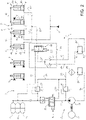
- Figures 1 and 2 discloses a hydraulic arrangement 1 according to the invention for a work vehicle (not shown) comprising a boom assembly provided with an operational element such as a scraper.
- the work vehicle may comprise an arm and an operational element that are controlled by respective hydraulic cylinders 2, 3 that will be not further described for sake of brevity.
- the work vehicle advantageously comprises a pair of boom cylinders 4, 5, namely a right cylinder 4 and a left cylinder 5 configured, together, to lift or lower the boom according to the vehicle operation.
- the cylinders 4, 5 comprise a housing 4a, 5a housing a sliding piston 4b, 5b in a tight manner thereby dividing the space defined by the housing into a piston chamber 4', 5' and a rod chamber 4", 5".
- cylinders 4, 5 are double actuated cylinders i.e. the piston and rod chambers 4', 5', 4", 5" are respectively fluidly connected to a source of fluid in pressure to control the operation of the cylinders 4, 5.
- the vehicle comprises an energy recovery system 7 comprising a pair of support cylinder 8, 9, i.e. a right support cylinder 8 and a left support cylinder 9.
- the left and right support cylinders 8, 9 are mechanically connected to, respectively, right and left cylinders 4, 5 as shown in the following.
- left and right support cylinders 8, 9 are preferably single acting cylinders therefore comprising a housing 8a, 9a that accommodates a piston 8b, 9b sliding in tight manner so as to divide the housing space into a piston chamber 8', 9' and a rod chamber 8", 9".
- pistons 8b, 9b of left and right support cylinders 8, 9 are respectively connected to pistons 4b, 5b of the left and right cylinders 4, 5 via a mechanical link 10, schematized by a line in the figures, that may be realized of any typology provided that the movement of one of pistons 8b, 9b is transferred to the other pistons 4b, 5b and vice versa.
- the energy recovery system 7 further comprises at least an accumulator 11, in the disclosed example three accumulators 11, that are fluidly connectable the left and right support cylinders 8, 9 via the hydraulic arrangement 1.
- Hydraulic arrangement 1 is fluidly interposed between accumulators 11 and support cylinders 8, 9 in order to manage their operation.
- hydraulic arrangement 1 comprises a feeding conduit 12 that is fluidly connectable between the accumulators 11 and left and right support cylinders 8, 9.
- hydraulic arrangement 1 comprises a balancing conduit 13 configured to fluidly connect together support cylinders 8, 9; in particular the balancing conduit 13 is fluidly connectable to the feeding conduit 12 from one side and, on the opposite side, comprises two branches 13', 13" both fluidly connected to a respective piston chamber 8', 9' of the cylinders 8, 9.
- the hydraulic arrangement 1 further comprises a filling module 15 configured to manage the filling of accumulators 11, when needed.
- the filling module 15 comprises pump means 16 preferably carried by a torque source 17 such as an electric motor.
- the pump means 16 are fluidly connected by a conduit 18 to a tank 20 and are configured to suck fluid from the tank and push this latter, in pressure, towards the accumulators 11.
- the pump means 16 are fluidly connected to accumulators via a conduit 21.
- the hydraulic arrangement 1 comprises valve means 22 configured to regulate the flow passage between the pump means 16 and the accumulators 11.
- the pump means may comprise a four ways proportional valve, preferably electro actuated, configured to allow the passage of fluid between a first configuration from pump means 16 towards accumulators 11 or a second opposite configuration, as better detailed hereinafter.
- the actuation is preferably given by a control signal S 1 that, in the disclosed embodiment is an electronic signal coming from a control unit.
- the hydraulic arrangement 1 further preferably comprises a relief valve 24 fluidly interposed on a conduit 25 that is fluidly connected between tank 20 and conduit 21.
- hydraulic arrangement 1 comprises filtering means 26 fluidly interposed on conduit 25 downstream to relief valve 24 and upstream to tank 20.
- the hydraulic arrangement 1 further preferably comprises a relief valve 27 fluidly interposed on a conduit 28 that is fluidly connected between conduit 21, downstream to valve means 22, and conduit 25 downstream to relief valve 24 and, preferably, upstream to filtering means 26.
- accumulators 11 and the valve means 22 may be provided a check valve piloted to regulate the pressure or to discharge pressure of accumulator 11 portion circuit.
- the hydraulic arrangement 1 comprises a selection module 31 configured to partition the fluid passage between accumulators 11, support cylinders 8, 9 and tank 20 according to a user's request.
- the selection module 31 comprises valve means 32 configured to regulate the fluid passage between tank 20 and support cylinders 8, 9.
- valve means 32 comprises a three ways proportional valve configured to allow the passage of fluid between a first configuration between accumulators 11 and support cylinders 8, 9 or a second opposite configuration between support cylinders 8, 9 and tank.
- the actuation is preferably given by a control signal S 2 that, in the disclosed embodiment is an electronic signal coming from a control unit.
- the selection module 31 further comprises a pair of check valves 33, 34 that are fluidly interposed on respective conduits 35, 36 that are both fluidly connected to tank 20, from one side and to valve means 32 on the opposite, in particular fluidly in parallel one with respect to the other.
- the two check valves 33, 34 are configured to allow the passage of fluid into two different opposite fluid directions.
- conduits 35, 36 are fluidly joint into a single conduit 37 towards valve means 32.
- the conduits 35, 36 are both fluidly connected to tank 20 in two different points X 1 , X 2 thereof.
- the conduit 36 housing check valve 34 that allows the passage of fluid from valve means towards tank 20 is fluidly connected to the tank 20 in a point X 1 placed vertically above with respect the point X 2 of connection of conduit 35.
- the hydraulic arrangement 1 comprises a further, buffer, tank 20' that is fluidly connected to only the fluid selection module 31 and the conduits 35, 36 are singularly fluidly connected to such buffer tank 20' in two different points X 1 , X 2 thereof.
- the tank 20 is fluidly connected only to accumulators 11 to manage their pressurization.
- conduit 36 housing check valve 34 that allows the passage of fluid from valve means towards tank 20' is fluidly connected to the tank 20' in a point X 1 placed vertically above with respect the point X 2 of connection of conduit 35.
- point X 1 is realized on a top wall defining tank 20, 20' and point X 2 is realized on a bottom wall defining tank 20, 20'.
- valve means 22 moves to allow the passage of fluid mainly between accumulators 11 and support cylinders 8, 9.
- pressurized fluid into accumulators 11 is used for helping lifting cylinders 4, 5, i.e. the lifting force of support cylinders 8, 9 is transmitted to cylinders 4, 5 via mechanical link 10.
- valve means 22 moves to allow the passage of fluid mainly between tank 20, 20' and support cylinders 8, 9. In this way, as per se known, cylinders 4, 5 are not helped in their work and excess fluid present in support cylinders 8, 9 will be discharged, when cylinders 4, 5 are lowered.
- the operation in the two embodiments is similar. The difference is that in first embodiment the fluid is discharged or sucked by a single tank 20 while in the second embodiment fluid may be discharged or sucked by the buffer tank 20'.
- the selection module 31 it is possible to select the recovery system 7 only when needed. Otherwise, the boom is operated only by cylinders 4, 5 as in vehicle that are not provided with a recovery system 7.
- the proposed work vehicle is more versatile with respect to existing system that are or provided with a recovery system either not.
- the provided arrangement of check valves with two different coupling points X 1 , X 2 optimizes the sucking and the filling of the tank 20.
- the system may be used with two different tanks, wherein one is a buffer for the great oil volume.
- the vehicle may be operated in standard way, i.e. the work vehicle can continue its operation without interruption.
- a proportional valve 32 is particularly advantageous since its control may be designed to decreased pump load when the boom lowers with better efficiency of the system. Accordingly, the work vehicle would decrease its fuel consumption. It is clear that modifications can be made to the described hydraulic arrangement and work vehicle which do not extend beyond the scope of protection defined by the claims.
- valve means and the topology of conduits may be varied.
- the filling module 15 may be realized in different ways, such as the number of accumulators 11 or the typology of cylinders may be varied.
Landscapes
- Engineering & Computer Science (AREA)
- General Engineering & Computer Science (AREA)
- Physics & Mathematics (AREA)
- Civil Engineering (AREA)
- Mining & Mineral Resources (AREA)
- Structural Engineering (AREA)
- Mechanical Engineering (AREA)
- Fluid Mechanics (AREA)
- Chemical & Material Sciences (AREA)
- Analytical Chemistry (AREA)
- Fluid-Pressure Circuits (AREA)
- Lubricants (AREA)
- Operation Control Of Excavators (AREA)
Abstract
the hydraulic arrangement (1) comprising a feeding conduit (12) fluidly connecting the accumulator (11) and the support cylinders (8, 9) and a selection module (31) fluidly interposed on the feeding conduit (12), the selection module (31) being configured to regulate the fluid passage between accumulator (11), support cylinders (8, 9) and a tank (20, 20') of the work vehicle.
Description
- The present invention concerns a hydraulic arrangement, in particular hydraulic arrangement for managing a recovery hydraulic functionality of a work vehicle.
- The present invention finds its preferred, although not exclusive, application in earth-moving vehicle provided with a boom such as a scraper.
- Work vehicles such as scrapers, i.e. vehicles provided with a hydraulic actuated boom, may be provided with so-called energy recovery systems.
- Energy recovery systems are configured to reduce the energy consumption during the movement of a boom that is controlled via a hydraulic actuator. Indeed, when the boom is controlled to be lowered, the fluid discharged by hydraulic actuator is stored to be used then the boom is controlled to be lifted.
- Such systems foresees the presence of accumulators to allow the storing of the fluid discharged by the actuator and a control block configured to manage the fluid flow between the accumulators, the tank and the actuator.
- However, if a vehicle is provided with such energy recovery system it is currently impossible to avoid its use. Accordingly, it is not possible, for instance, making boom cylinders to be discharged as in standard operation.
- Therefore, the need is felt to allow the use of the energy recovery system only when needed by the typology of work executed by the work vehicle.
- An aim of the present invention is to satisfy the above mentioned needs.
- The aforementioned aim is reached by a hydraulic arrangement and a work vehicle as claimed in the appended set of claims.
- For a better understanding of the present invention, a preferred embodiment is described in the following, by way of a non-limiting example, with reference to the attached drawings wherein:
-
Figure 1 is a schematic representation of the hydraulic arrangement according to an embodiment of the invention; and -
Figure 2 is a schematic representation of the hydraulic arrangement according to an alternative embodiment of the invention. -
Figures 1 and2 discloses a hydraulic arrangement 1 according to the invention for a work vehicle (not shown) comprising a boom assembly provided with an operational element such as a scraper. - Accordingly, the work vehicle may comprise an arm and an operational element that are controlled by respective
hydraulic cylinders - The work vehicle advantageously comprises a pair of
boom cylinders right cylinder 4 and aleft cylinder 5 configured, together, to lift or lower the boom according to the vehicle operation. - As shown in the exemplarily drawings, the
cylinders housing sliding piston rod chamber 4", 5". Preferably,cylinders rod chambers 4', 5', 4", 5" are respectively fluidly connected to a source of fluid in pressure to control the operation of thecylinders - The vehicle comprises an energy recovery system 7 comprising a pair of
support cylinder right support cylinder 8 and aleft support cylinder 9. The left andright support cylinders left cylinders - In detail, left and
right support cylinders housing piston rod chamber 8", 9". - Advantageously, the
pistons right support cylinders pistons right cylinders mechanical link 10, schematized by a line in the figures, that may be realized of any typology provided that the movement of one ofpistons other pistons - The energy recovery system 7 further comprises at least an
accumulator 11, in the disclosed example threeaccumulators 11, that are fluidly connectable the left andright support cylinders - Hydraulic arrangement 1 is fluidly interposed between
accumulators 11 andsupport cylinders feeding conduit 12 that is fluidly connectable between theaccumulators 11 and left andright support cylinders - Furthermore, hydraulic arrangement 1 comprises a balancing
conduit 13 configured to fluidly connect togethersupport cylinders conduit 13 is fluidly connectable to thefeeding conduit 12 from one side and, on the opposite side, comprises twobranches 13', 13" both fluidly connected to a respective piston chamber 8', 9' of thecylinders - The hydraulic arrangement 1 further comprises a
filling module 15 configured to manage the filling ofaccumulators 11, when needed. - Accordingly, the
filling module 15 comprises pump means 16 preferably carried by atorque source 17 such as an electric motor. The pump means 16 are fluidly connected by aconduit 18 to atank 20 and are configured to suck fluid from the tank and push this latter, in pressure, towards theaccumulators 11. - The pump means 16 are fluidly connected to accumulators via a
conduit 21. Preferably, the hydraulic arrangement 1 comprises valve means 22 configured to regulate the flow passage between the pump means 16 and theaccumulators 11. - In detail, the pump means may comprise a four ways proportional valve, preferably electro actuated, configured to allow the passage of fluid between a first configuration from pump means 16 towards
accumulators 11 or a second opposite configuration, as better detailed hereinafter. - The actuation is preferably given by a control signal S1 that, in the disclosed embodiment is an electronic signal coming from a control unit.
- The hydraulic arrangement 1 further preferably comprises a
relief valve 24 fluidly interposed on aconduit 25 that is fluidly connected betweentank 20 andconduit 21. - Preferably, hydraulic arrangement 1 comprises filtering means 26 fluidly interposed on
conduit 25 downstream torelief valve 24 and upstream totank 20. - The hydraulic arrangement 1 further preferably comprises a
relief valve 27 fluidly interposed on aconduit 28 that is fluidly connected betweenconduit 21, downstream to valve means 22, and conduit 25 downstream torelief valve 24 and, preferably, upstream to filteringmeans 26. - Between the
relief valve 27,accumulators 11 and the valve means 22 it may be provided a check valve piloted to regulate the pressure or to discharge pressure ofaccumulator 11 portion circuit. - According to the invention, the hydraulic arrangement 1 comprises a
selection module 31 configured to partition the fluid passage betweenaccumulators 11,support cylinders tank 20 according to a user's request. - In particular, the
selection module 31 comprises valve means 32 configured to regulate the fluid passage betweentank 20 andsupport cylinders - Preferably, valve means 32 comprises a three ways proportional valve configured to allow the passage of fluid between a first configuration between
accumulators 11 andsupport cylinders support cylinders - The actuation is preferably given by a control signal S2 that, in the disclosed embodiment is an electronic signal coming from a control unit.
- The
selection module 31 further comprises a pair ofcheck valves respective conduits tank 20, from one side and to valve means 32 on the opposite, in particular fluidly in parallel one with respect to the other. - In particular the two
check valves - Preferably,
conduits single conduit 37 towards valve means 32. - According to the embodiment of
figure 1 , theconduits tank 20 in two different points X1, X2 thereof. In detail, theconduit 36housing check valve 34 that allows the passage of fluid from valve means towardstank 20 is fluidly connected to thetank 20 in a point X1 placed vertically above with respect the point X2 of connection ofconduit 35. - According to the embodiment of
figure 2 , the hydraulic arrangement 1 comprises a further, buffer, tank 20' that is fluidly connected to only thefluid selection module 31 and theconduits tank 20 is fluidly connected only toaccumulators 11 to manage their pressurization. - In detail, the
conduit 36housing check valve 34 that allows the passage of fluid from valve means towards tank 20' is fluidly connected to the tank 20' in a point X1 placed vertically above with respect the point X2 of connection ofconduit 35. - In both embodiments, advantageously, point X1 is realized on a top
wall defining tank 20, 20' and point X2 is realized on a bottomwall defining tank 20, 20'. - The operation of the two above described embodiments according to the invention is the following.
- According to a first mode of operation it is provided a signal S2 (e.g. directly by the user via a button/ display) enabling the use of the energy recovery system 7. Accordingly, valve means 22 moves to allow the passage of fluid mainly between
accumulators 11 andsupport cylinders accumulators 11 is used for helping liftingcylinders support cylinders cylinders mechanical link 10. - According to a second mode of the provided signal S2 disables the use of the energy recovery system 7. Accordingly, valve means 22 moves to allow the passage of fluid mainly between
tank 20, 20' andsupport cylinders cylinders support cylinders cylinders - The operation in the two embodiments is similar. The difference is that in first embodiment the fluid is discharged or sucked by a
single tank 20 while in the second embodiment fluid may be discharged or sucked by the buffer tank 20'. - In view of the foregoing, the advantages of a hydraulic arrangement and a work vehicle according to the invention are apparent.
- Thanks to the
selection module 31, it is possible to select the recovery system 7 only when needed. Otherwise, the boom is operated only bycylinders - In this way, the proposed work vehicle is more versatile with respect to existing system that are or provided with a recovery system either not.
- Moreover, the provided arrangement of check valves with two different coupling points X1, X2 optimizes the sucking and the filling of the
tank 20. - Furthermore, if the oil volume is too great for a single tank, the system may be used with two different tanks, wherein one is a buffer for the great oil volume.
- Furthermore, in case of failure of
accumulators 11 or of any other system of the recovery system 7, the vehicle may be operated in standard way, i.e. the work vehicle can continue its operation without interruption. - Moreover, the use of a
proportional valve 32 is particularly advantageous since its control may be designed to decreased pump load when the boom lowers with better efficiency of the system. Accordingly, the work vehicle would decrease its fuel consumption. It is clear that modifications can be made to the described hydraulic arrangement and work vehicle which do not extend beyond the scope of protection defined by the claims. - For example, the proposed valve means and the topology of conduits may be varied.
- Furthermore, the filling
module 15 may be realized in different ways, such as the number ofaccumulators 11 or the typology of cylinders may be varied.
Claims (11)
- Hydraulic arrangement (1) for a work vehicle provided with a boom configured to be controlled via a pair of cylinders (4, 5) and an energy recovery system (7) comprising a pair of support cylinders (8, 9) configured to cooperate with said pair of cylinders (4, 5) and at least an accumulator (11),
said hydraulic arrangement (1) comprising a feeding conduit (12) fluidly connecting said accumulator (11) and said support cylinders (8, 9) and a selection module (31) fluidly interposed on said feeding conduit (12), said selection module (31) being configured to regulate the fluid passage between said accumulator (11), said support cylinders (8, 9) and a tank (20, 20') of said work vehicle. - Hydraulic arrangement according to claim 1, wherein said selection module (1) comprises valves means (32) fluidly interposed on said feeding conduit (12) and said tank (20, 20'), said valve means(32) comprising an electro-actuated valve.
- Hydraulic arrangement according to claim 1 or 2, wherein said selection module (1) comprises valves means (32) fluidly interposed on said feeding conduit (12) and said tank (20, 20'), said valve means(32) comprising a proportional valve.
- Hydraulic arrangement according to claims 2 or 3, wherein said selection module (31) comprises pair of check valves (33, 34) fluidly interposed on respective conduits (35, 36), said conduits (35, 36) being fluidly in parallel between said tank (20,20') and said valve means (32), said check valves (33, 34) allowing the passage of fluid each in a direction opposite with respect to the other.
- Hydraulic arrangement according to claim 4, wherein said conduits (35, 36), opposite to said tank (20, 20') are joint into a common conduit (37) that is fluidly connected to said valve means (32).
- Hydraulic arrangement according to claims 4 or 5, wherein one of said conduits (36) carries a check valve (34) configured to allow the passage of fluid only from said valve means (32) to said tank (20, 20') and the other of said conduits (35) carries a check valve (33) configured to allow the passage of fluid only from said tank (20, 20') to said valve means (32), said one conduit (36) being connected to tank (20, 20') in a first position (X1) and said other conduit (35) being connected to tank (20, 20') in a second position (X2), said first position (X1) being vertically upper with respect to said second position (X2).
- Hydraulic arrangement according to claim 6, wherein said first position (X1) being realized on a top wall of said tank (20, 20') and said second position (X2) being realized on a bottom wall of said tank (20, 20').
- Hydraulic arrangement according to any of the preceding claims, wherein said work vehicle comprises a tank (20) fluidly connected to said accumulators (11) and a buffer tank (20') distinct with respect to said tank (20), said buffer tank (20') being fluidly connected only to said selection module (31).
- Hydraulic arrangement according to claim 8 when depending on claim 6, wherein said conduits (35, 36) are fluidly connected to said buffer tank (20').
- Hydraulic arrangement according to any of said preceding claims comprising a filling module (15) fluidly interposed between said tank (20, 20') and said accumulator (11), said filling module (15) being configured to charge said accumulators (11).
- Work vehicle provided with a boom configured to be controlled via a pair of cylinders (4, 5) and an energy recovery system (7) comprising a pair of support cylinders (8, 9) configured to cooperate with said pair of cylinders (4, 5) and at least an accumulator (11), said work vehicle comprising at least one tank (20, 20') and a hydraulic arrangement according to any of the preceding claims.
Applications Claiming Priority (1)
| Application Number | Priority Date | Filing Date | Title |
|---|---|---|---|
| IT102021000017045A IT202100017045A1 (en) | 2021-06-29 | 2021-06-29 | HYDRAULIC ARRANGEMENT TO MANAGE A HYDRAULIC RECOVERY FUNCTION |
Publications (2)
| Publication Number | Publication Date |
|---|---|
| EP4112946A1 true EP4112946A1 (en) | 2023-01-04 |
| EP4112946B1 EP4112946B1 (en) | 2025-01-08 |
Family
ID=77802114
Family Applications (1)
| Application Number | Title | Priority Date | Filing Date |
|---|---|---|---|
| EP22180245.7A Active EP4112946B1 (en) | 2021-06-29 | 2022-06-21 | Hydraulic arrangement for a work vehicle |
Country Status (2)
| Country | Link |
|---|---|
| EP (1) | EP4112946B1 (en) |
| IT (1) | IT202100017045A1 (en) |
Cited By (1)
| Publication number | Priority date | Publication date | Assignee | Title |
|---|---|---|---|---|
| CN118727855A (en) * | 2024-08-12 | 2024-10-01 | 潍柴动力股份有限公司 | Working device, loader and working device control method |
Citations (5)
| Publication number | Priority date | Publication date | Assignee | Title |
|---|---|---|---|---|
| JPH04120324A (en) * | 1990-09-10 | 1992-04-21 | Komatsu Ltd | Work equipment potential energy recovery and utilization device |
| US6918247B1 (en) * | 2003-11-19 | 2005-07-19 | Jack E Warner | Assisted hydraulic system for moving a structural member |
| JP3929380B2 (en) * | 2002-09-26 | 2007-06-13 | 株式会社小松製作所 | Position energy recovery / regeneration device for work equipment |
| JP2013145035A (en) * | 2012-01-16 | 2013-07-25 | Sumitomo Heavy Ind Ltd | Construction machine energy regeneration device |
| EP2690292A1 (en) * | 2011-03-21 | 2014-01-29 | Shuanglai Yang | Lifting system and lifting method for jib of project machine and project machine thereof |
-
2021
- 2021-06-29 IT IT102021000017045A patent/IT202100017045A1/en unknown
-
2022
- 2022-06-21 EP EP22180245.7A patent/EP4112946B1/en active Active
Patent Citations (5)
| Publication number | Priority date | Publication date | Assignee | Title |
|---|---|---|---|---|
| JPH04120324A (en) * | 1990-09-10 | 1992-04-21 | Komatsu Ltd | Work equipment potential energy recovery and utilization device |
| JP3929380B2 (en) * | 2002-09-26 | 2007-06-13 | 株式会社小松製作所 | Position energy recovery / regeneration device for work equipment |
| US6918247B1 (en) * | 2003-11-19 | 2005-07-19 | Jack E Warner | Assisted hydraulic system for moving a structural member |
| EP2690292A1 (en) * | 2011-03-21 | 2014-01-29 | Shuanglai Yang | Lifting system and lifting method for jib of project machine and project machine thereof |
| JP2013145035A (en) * | 2012-01-16 | 2013-07-25 | Sumitomo Heavy Ind Ltd | Construction machine energy regeneration device |
Cited By (2)
| Publication number | Priority date | Publication date | Assignee | Title |
|---|---|---|---|---|
| CN118727855A (en) * | 2024-08-12 | 2024-10-01 | 潍柴动力股份有限公司 | Working device, loader and working device control method |
| CN118727855B (en) * | 2024-08-12 | 2025-09-19 | 潍柴动力股份有限公司 | Working device, loader, and working device control method |
Also Published As
| Publication number | Publication date |
|---|---|
| IT202100017045A1 (en) | 2022-12-29 |
| EP4112946B1 (en) | 2025-01-08 |
Similar Documents
| Publication | Publication Date | Title |
|---|---|---|
| EP2679735B1 (en) | Construction machine with working attachment | |
| CA2628998C (en) | Flow continuity for multiple hydraulic circuits and associated method | |
| US20130098023A1 (en) | Energy recovery control circuit and work machine | |
| US20100000209A1 (en) | Hydraulic control system in working machine ( as amended | |
| CN103906931B (en) | Hydraulic driving system | |
| KR102331223B1 (en) | Pressure oil energy recovery device of working machine | |
| CN103562568B (en) | Hydraulic system and method for controlling a hydraulic system | |
| CN104093979B (en) | Fluid pressure increase and decrease press and construction machinery | |
| WO2013059020A1 (en) | Closed-loop hydraulic system having regeneration configuration | |
| US11927205B2 (en) | Hydraulic system | |
| US12404878B2 (en) | Actuating device for at least one fluidically drivable consumer | |
| KR102535297B1 (en) | fluid circuit | |
| EP3280847B1 (en) | A load sensing hydraulic system for a working machine, and a method for controlling a load sensing hydraulic system | |
| EP4112946B1 (en) | Hydraulic arrangement for a work vehicle | |
| US6282890B1 (en) | Hydraulic circuit for construction machines | |
| WO2011133849A1 (en) | Pump suction charging system | |
| CN113825881B (en) | Hydraulic equipment, hydraulic system and working machine | |
| CN112360833A (en) | Flow control system, flow control method and crane | |
| JP7400915B1 (en) | Pump system and vehicle equipped with it | |
| US11946224B2 (en) | Construction machine | |
| EP3786461A1 (en) | Directional valve for a work vehicle and related hydraulic arrangement | |
| JP2008185099A (en) | Control system in working machine | |
| US20120125459A1 (en) | Hydraulic Main Valve and Auxillary Valve | |
| US12043983B2 (en) | Construction machine | |
| CN217976873U (en) | Control valve device and hydraulically driven machine equipped with the control valve device |
Legal Events
| Date | Code | Title | Description |
|---|---|---|---|
| PUAI | Public reference made under article 153(3) epc to a published international application that has entered the european phase |
Free format text: ORIGINAL CODE: 0009012 |
|
| STAA | Information on the status of an ep patent application or granted ep patent |
Free format text: STATUS: THE APPLICATION HAS BEEN PUBLISHED |
|
| AK | Designated contracting states |
Kind code of ref document: A1 Designated state(s): AL AT BE BG CH CY CZ DE DK EE ES FI FR GB GR HR HU IE IS IT LI LT LU LV MC MK MT NL NO PL PT RO RS SE SI SK SM TR |
|
| STAA | Information on the status of an ep patent application or granted ep patent |
Free format text: STATUS: REQUEST FOR EXAMINATION WAS MADE |
|
| 17P | Request for examination filed |
Effective date: 20230704 |
|
| RBV | Designated contracting states (corrected) |
Designated state(s): AL AT BE BG CH CY CZ DE DK EE ES FI FR GB GR HR HU IE IS IT LI LT LU LV MC MK MT NL NO PL PT RO RS SE SI SK SM TR |
|
| GRAP | Despatch of communication of intention to grant a patent |
Free format text: ORIGINAL CODE: EPIDOSNIGR1 |
|
| STAA | Information on the status of an ep patent application or granted ep patent |
Free format text: STATUS: GRANT OF PATENT IS INTENDED |
|
| INTG | Intention to grant announced |
Effective date: 20240328 |
|
| GRAJ | Information related to disapproval of communication of intention to grant by the applicant or resumption of examination proceedings by the epo deleted |
Free format text: ORIGINAL CODE: EPIDOSDIGR1 |
|
| STAA | Information on the status of an ep patent application or granted ep patent |
Free format text: STATUS: REQUEST FOR EXAMINATION WAS MADE |
|
| GRAP | Despatch of communication of intention to grant a patent |
Free format text: ORIGINAL CODE: EPIDOSNIGR1 |
|
| STAA | Information on the status of an ep patent application or granted ep patent |
Free format text: STATUS: GRANT OF PATENT IS INTENDED |
|
| INTG | Intention to grant announced |
Effective date: 20240729 |
|
| GRAS | Grant fee paid |
Free format text: ORIGINAL CODE: EPIDOSNIGR3 |
|
| GRAA | (expected) grant |
Free format text: ORIGINAL CODE: 0009210 |
|
| STAA | Information on the status of an ep patent application or granted ep patent |
Free format text: STATUS: THE PATENT HAS BEEN GRANTED |
|
| AK | Designated contracting states |
Kind code of ref document: B1 Designated state(s): AL AT BE BG CH CY CZ DE DK EE ES FI FR GB GR HR HU IE IS IT LI LT LU LV MC MK MT NL NO PL PT RO RS SE SI SK SM TR |
|
| REG | Reference to a national code |
Ref country code: GB Ref legal event code: FG4D |
|
| REG | Reference to a national code |
Ref country code: CH Ref legal event code: EP |
|
| REG | Reference to a national code |
Ref country code: DE Ref legal event code: R096 Ref document number: 602022009507 Country of ref document: DE |
|
| REG | Reference to a national code |
Ref country code: IE Ref legal event code: FG4D |
|
| REG | Reference to a national code |
Ref country code: LT Ref legal event code: MG9D |
|
| REG | Reference to a national code |
Ref country code: NL Ref legal event code: MP Effective date: 20250108 |
|
| REG | Reference to a national code |
Ref country code: AT Ref legal event code: MK05 Ref document number: 1758493 Country of ref document: AT Kind code of ref document: T Effective date: 20250108 |
|
| PG25 | Lapsed in a contracting state [announced via postgrant information from national office to epo] |
Ref country code: NL Free format text: LAPSE BECAUSE OF FAILURE TO SUBMIT A TRANSLATION OF THE DESCRIPTION OR TO PAY THE FEE WITHIN THE PRESCRIBED TIME-LIMIT Effective date: 20250108 |
|
| PG25 | Lapsed in a contracting state [announced via postgrant information from national office to epo] |
Ref country code: RS Free format text: LAPSE BECAUSE OF FAILURE TO SUBMIT A TRANSLATION OF THE DESCRIPTION OR TO PAY THE FEE WITHIN THE PRESCRIBED TIME-LIMIT Effective date: 20250408 |
|
| PG25 | Lapsed in a contracting state [announced via postgrant information from national office to epo] |
Ref country code: PL Free format text: LAPSE BECAUSE OF FAILURE TO SUBMIT A TRANSLATION OF THE DESCRIPTION OR TO PAY THE FEE WITHIN THE PRESCRIBED TIME-LIMIT Effective date: 20250108 |
|
| PG25 | Lapsed in a contracting state [announced via postgrant information from national office to epo] |
Ref country code: ES Free format text: LAPSE BECAUSE OF FAILURE TO SUBMIT A TRANSLATION OF THE DESCRIPTION OR TO PAY THE FEE WITHIN THE PRESCRIBED TIME-LIMIT Effective date: 20250108 |
|
| PG25 | Lapsed in a contracting state [announced via postgrant information from national office to epo] |
Ref country code: NO Free format text: LAPSE BECAUSE OF FAILURE TO SUBMIT A TRANSLATION OF THE DESCRIPTION OR TO PAY THE FEE WITHIN THE PRESCRIBED TIME-LIMIT Effective date: 20250408 Ref country code: IS Free format text: LAPSE BECAUSE OF FAILURE TO SUBMIT A TRANSLATION OF THE DESCRIPTION OR TO PAY THE FEE WITHIN THE PRESCRIBED TIME-LIMIT Effective date: 20250508 |
|
| PG25 | Lapsed in a contracting state [announced via postgrant information from national office to epo] |
Ref country code: HR Free format text: LAPSE BECAUSE OF FAILURE TO SUBMIT A TRANSLATION OF THE DESCRIPTION OR TO PAY THE FEE WITHIN THE PRESCRIBED TIME-LIMIT Effective date: 20250108 |
|
| PG25 | Lapsed in a contracting state [announced via postgrant information from national office to epo] |
Ref country code: PT Free format text: LAPSE BECAUSE OF FAILURE TO SUBMIT A TRANSLATION OF THE DESCRIPTION OR TO PAY THE FEE WITHIN THE PRESCRIBED TIME-LIMIT Effective date: 20250508 Ref country code: LV Free format text: LAPSE BECAUSE OF FAILURE TO SUBMIT A TRANSLATION OF THE DESCRIPTION OR TO PAY THE FEE WITHIN THE PRESCRIBED TIME-LIMIT Effective date: 20250108 |
|
| PG25 | Lapsed in a contracting state [announced via postgrant information from national office to epo] |
Ref country code: GR Free format text: LAPSE BECAUSE OF FAILURE TO SUBMIT A TRANSLATION OF THE DESCRIPTION OR TO PAY THE FEE WITHIN THE PRESCRIBED TIME-LIMIT Effective date: 20250409 Ref country code: BG Free format text: LAPSE BECAUSE OF FAILURE TO SUBMIT A TRANSLATION OF THE DESCRIPTION OR TO PAY THE FEE WITHIN THE PRESCRIBED TIME-LIMIT Effective date: 20250108 |
|
| PG25 | Lapsed in a contracting state [announced via postgrant information from national office to epo] |
Ref country code: AT Free format text: LAPSE BECAUSE OF FAILURE TO SUBMIT A TRANSLATION OF THE DESCRIPTION OR TO PAY THE FEE WITHIN THE PRESCRIBED TIME-LIMIT Effective date: 20250108 |
|
| PG25 | Lapsed in a contracting state [announced via postgrant information from national office to epo] |
Ref country code: SE Free format text: LAPSE BECAUSE OF FAILURE TO SUBMIT A TRANSLATION OF THE DESCRIPTION OR TO PAY THE FEE WITHIN THE PRESCRIBED TIME-LIMIT Effective date: 20250108 |
|
| PG25 | Lapsed in a contracting state [announced via postgrant information from national office to epo] |
Ref country code: SM Free format text: LAPSE BECAUSE OF FAILURE TO SUBMIT A TRANSLATION OF THE DESCRIPTION OR TO PAY THE FEE WITHIN THE PRESCRIBED TIME-LIMIT Effective date: 20250108 |
|
| REG | Reference to a national code |
Ref country code: DE Ref legal event code: R097 Ref document number: 602022009507 Country of ref document: DE |
|
| PG25 | Lapsed in a contracting state [announced via postgrant information from national office to epo] |
Ref country code: DK Free format text: LAPSE BECAUSE OF FAILURE TO SUBMIT A TRANSLATION OF THE DESCRIPTION OR TO PAY THE FEE WITHIN THE PRESCRIBED TIME-LIMIT Effective date: 20250108 |
|
| PG25 | Lapsed in a contracting state [announced via postgrant information from national office to epo] |
Ref country code: CZ Free format text: LAPSE BECAUSE OF FAILURE TO SUBMIT A TRANSLATION OF THE DESCRIPTION OR TO PAY THE FEE WITHIN THE PRESCRIBED TIME-LIMIT Effective date: 20250108 Ref country code: EE Free format text: LAPSE BECAUSE OF FAILURE TO SUBMIT A TRANSLATION OF THE DESCRIPTION OR TO PAY THE FEE WITHIN THE PRESCRIBED TIME-LIMIT Effective date: 20250108 |
|
| PG25 | Lapsed in a contracting state [announced via postgrant information from national office to epo] |
Ref country code: RO Free format text: LAPSE BECAUSE OF FAILURE TO SUBMIT A TRANSLATION OF THE DESCRIPTION OR TO PAY THE FEE WITHIN THE PRESCRIBED TIME-LIMIT Effective date: 20250108 |
|
| PG25 | Lapsed in a contracting state [announced via postgrant information from national office to epo] |
Ref country code: SK Free format text: LAPSE BECAUSE OF FAILURE TO SUBMIT A TRANSLATION OF THE DESCRIPTION OR TO PAY THE FEE WITHIN THE PRESCRIBED TIME-LIMIT Effective date: 20250108 |
|
| PLBE | No opposition filed within time limit |
Free format text: ORIGINAL CODE: 0009261 |
|
| STAA | Information on the status of an ep patent application or granted ep patent |
Free format text: STATUS: NO OPPOSITION FILED WITHIN TIME LIMIT |
|
| REG | Reference to a national code |
Ref country code: CH Ref legal event code: L10 Free format text: ST27 STATUS EVENT CODE: U-0-0-L10-L00 (AS PROVIDED BY THE NATIONAL OFFICE) Effective date: 20251119 |
|
| 26N | No opposition filed |
Effective date: 20251009 |
|
| REG | Reference to a national code |
Ref country code: CH Ref legal event code: H13 Free format text: ST27 STATUS EVENT CODE: U-0-0-H10-H13 (AS PROVIDED BY THE NATIONAL OFFICE) Effective date: 20260127 |
|
| PG25 | Lapsed in a contracting state [announced via postgrant information from national office to epo] |
Ref country code: MC Free format text: LAPSE BECAUSE OF FAILURE TO SUBMIT A TRANSLATION OF THE DESCRIPTION OR TO PAY THE FEE WITHIN THE PRESCRIBED TIME-LIMIT Effective date: 20250108 |
|
| PG25 | Lapsed in a contracting state [announced via postgrant information from national office to epo] |
Ref country code: LU Free format text: LAPSE BECAUSE OF NON-PAYMENT OF DUE FEES Effective date: 20250621 |
|
| REG | Reference to a national code |
Ref country code: BE Ref legal event code: MM Effective date: 20250630 |
|
| PG25 | Lapsed in a contracting state [announced via postgrant information from national office to epo] |
Ref country code: IE Free format text: LAPSE BECAUSE OF NON-PAYMENT OF DUE FEES Effective date: 20250621 |
|
| PG25 | Lapsed in a contracting state [announced via postgrant information from national office to epo] |
Ref country code: BE Free format text: LAPSE BECAUSE OF NON-PAYMENT OF DUE FEES Effective date: 20250630 |
|
| PG25 | Lapsed in a contracting state [announced via postgrant information from national office to epo] |
Ref country code: CH Free format text: LAPSE BECAUSE OF NON-PAYMENT OF DUE FEES Effective date: 20250630 |
|
| PG25 | Lapsed in a contracting state [announced via postgrant information from national office to epo] |
Ref country code: LT Free format text: LAPSE BECAUSE OF FAILURE TO SUBMIT A TRANSLATION OF THE DESCRIPTION OR TO PAY THE FEE WITHIN THE PRESCRIBED TIME-LIMIT Effective date: 20250108 |
|
| PGFP | Annual fee paid to national office [announced via postgrant information from national office to epo] |
Ref country code: GB Payment date: 20260622 Year of fee payment: 5 |
|
| PGFP | Annual fee paid to national office [announced via postgrant information from national office to epo] |
Ref country code: IT Payment date: 20260623 Year of fee payment: 5 |
|
| PGFP | Annual fee paid to national office [announced via postgrant information from national office to epo] |
Ref country code: DE Payment date: 20260623 Year of fee payment: 5 |
|
| PG25 | Lapsed in a contracting state [announced via postgrant information from national office to epo] |
Ref country code: FI Free format text: LAPSE BECAUSE OF FAILURE TO SUBMIT A TRANSLATION OF THE DESCRIPTION OR TO PAY THE FEE WITHIN THE PRESCRIBED TIME-LIMIT Effective date: 20250108 |
|
| PGFP | Annual fee paid to national office [announced via postgrant information from national office to epo] |
Ref country code: FR Payment date: 20260622 Year of fee payment: 5 |
|
| PG25 | Lapsed in a contracting state [announced via postgrant information from national office to epo] |
Ref country code: CY Free format text: LAPSE BECAUSE OF FAILURE TO SUBMIT A TRANSLATION OF THE DESCRIPTION OR TO PAY THE FEE WITHIN THE PRESCRIBED TIME-LIMIT Effective date: 20250108 |