EP4112938B1 - Rotary heat pump, and air conditioner and automobile equipped with same - Google Patents
Rotary heat pump, and air conditioner and automobile equipped with same Download PDFInfo
- Publication number
- EP4112938B1 EP4112938B1 EP21919260.6A EP21919260A EP4112938B1 EP 4112938 B1 EP4112938 B1 EP 4112938B1 EP 21919260 A EP21919260 A EP 21919260A EP 4112938 B1 EP4112938 B1 EP 4112938B1
- Authority
- EP
- European Patent Office
- Prior art keywords
- rotary
- housing
- heat pump
- rotor
- region
- Prior art date
- Legal status (The legal status is an assumption and is not a legal conclusion. Google has not performed a legal analysis and makes no representation as to the accuracy of the status listed.)
- Active
Links
Images


Classifications
-
- F—MECHANICAL ENGINEERING; LIGHTING; HEATING; WEAPONS; BLASTING
- F02—COMBUSTION ENGINES; HOT-GAS OR COMBUSTION-PRODUCT ENGINE PLANTS
- F02G—HOT GAS OR COMBUSTION-PRODUCT POSITIVE-DISPLACEMENT ENGINE PLANTS; USE OF WASTE HEAT OF COMBUSTION ENGINES; NOT OTHERWISE PROVIDED FOR
- F02G1/00—Hot gas positive-displacement engine plants
- F02G1/04—Hot gas positive-displacement engine plants of closed-cycle type
- F02G1/043—Hot gas positive-displacement engine plants of closed-cycle type the engine being operated by expansion and contraction of a mass of working gas which is heated and cooled in one of a plurality of constantly communicating expansible chambers, e.g. Stirling cycle type engines
- F02G1/053—Component parts or details
- F02G1/055—Heaters or coolers
-
- F—MECHANICAL ENGINEERING; LIGHTING; HEATING; WEAPONS; BLASTING
- F01—MACHINES OR ENGINES IN GENERAL; ENGINE PLANTS IN GENERAL; STEAM ENGINES
- F01C—ROTARY-PISTON OR OSCILLATING-PISTON MACHINES OR ENGINES
- F01C1/00—Rotary-piston machines or engines
- F01C1/22—Rotary-piston machines or engines of internal-axis type with equidirectional movement of co-operating members at the points of engagement, or with one of the co-operating members being stationary, the inner member having more teeth or tooth- equivalents than the outer member
-
- F—MECHANICAL ENGINEERING; LIGHTING; HEATING; WEAPONS; BLASTING
- F01—MACHINES OR ENGINES IN GENERAL; ENGINE PLANTS IN GENERAL; STEAM ENGINES
- F01C—ROTARY-PISTON OR OSCILLATING-PISTON MACHINES OR ENGINES
- F01C21/00—Component parts, details or accessories not provided for in groups F01C1/00 - F01C20/00
- F01C21/06—Heating; Cooling; Heat insulation
-
- F—MECHANICAL ENGINEERING; LIGHTING; HEATING; WEAPONS; BLASTING
- F02—COMBUSTION ENGINES; HOT-GAS OR COMBUSTION-PRODUCT ENGINE PLANTS
- F02G—HOT GAS OR COMBUSTION-PRODUCT POSITIVE-DISPLACEMENT ENGINE PLANTS; USE OF WASTE HEAT OF COMBUSTION ENGINES; NOT OTHERWISE PROVIDED FOR
- F02G1/00—Hot gas positive-displacement engine plants
- F02G1/04—Hot gas positive-displacement engine plants of closed-cycle type
- F02G1/043—Hot gas positive-displacement engine plants of closed-cycle type the engine being operated by expansion and contraction of a mass of working gas which is heated and cooled in one of a plurality of constantly communicating expansible chambers, e.g. Stirling cycle type engines
- F02G1/044—Hot gas positive-displacement engine plants of closed-cycle type the engine being operated by expansion and contraction of a mass of working gas which is heated and cooled in one of a plurality of constantly communicating expansible chambers, e.g. Stirling cycle type engines having at least two working members, e.g. pistons, delivering power output
- F02G1/0445—Engine plants with combined cycles, e.g. Vuilleumier
-
- F—MECHANICAL ENGINEERING; LIGHTING; HEATING; WEAPONS; BLASTING
- F04—POSITIVE - DISPLACEMENT MACHINES FOR LIQUIDS; PUMPS FOR LIQUIDS OR ELASTIC FLUIDS
- F04C—ROTARY-PISTON, OR OSCILLATING-PISTON, POSITIVE-DISPLACEMENT MACHINES FOR LIQUIDS; ROTARY-PISTON, OR OSCILLATING-PISTON, POSITIVE-DISPLACEMENT PUMPS
- F04C18/00—Rotary-piston pumps specially adapted for elastic fluids
- F04C18/22—Rotary-piston pumps specially adapted for elastic fluids of internal-axis type with equidirectional movement of co-operating members at the points of engagement, or with one of the co-operating members being stationary, the inner member having more teeth or tooth equivalents than the outer member
-
- F—MECHANICAL ENGINEERING; LIGHTING; HEATING; WEAPONS; BLASTING
- F04—POSITIVE - DISPLACEMENT MACHINES FOR LIQUIDS; PUMPS FOR LIQUIDS OR ELASTIC FLUIDS
- F04C—ROTARY-PISTON, OR OSCILLATING-PISTON, POSITIVE-DISPLACEMENT MACHINES FOR LIQUIDS; ROTARY-PISTON, OR OSCILLATING-PISTON, POSITIVE-DISPLACEMENT PUMPS
- F04C29/00—Component parts, details or accessories of pumps or pumping installations, not provided for in groups F04C18/00 - F04C28/00
- F04C29/04—Heating; Cooling; Heat insulation
-
- F—MECHANICAL ENGINEERING; LIGHTING; HEATING; WEAPONS; BLASTING
- F25—REFRIGERATION OR COOLING; COMBINED HEATING AND REFRIGERATION SYSTEMS; HEAT PUMP SYSTEMS; MANUFACTURE OR STORAGE OF ICE; LIQUEFACTION SOLIDIFICATION OF GASES
- F25B—REFRIGERATION MACHINES, PLANTS OR SYSTEMS; COMBINED HEATING AND REFRIGERATION SYSTEMS; HEAT PUMP SYSTEMS
- F25B9/00—Compression machines, plants or systems, in which the refrigerant is air or other gas of low boiling point
- F25B9/14—Compression machines, plants or systems, in which the refrigerant is air or other gas of low boiling point characterised by the cycle used, e.g. Stirling cycle
Definitions
- the present invention relates to a rotary heat pump, and an air conditioner and an automobile each equipped with the same.
- JP H02 118363A refers to a heat pump device in a compact structure by utilizing the basic constitution of a rotary piston engine and separating a compression section from an expansion section.
- WO 2010/125375 A2 discloses a unitary rotor side-seal member arranged to be coupled to a flank of a rotor of a rotary engine.
- US 2004/200217 A1 refers to a rotary engine, comprising a stator that includes a bladed heat transfer stator segment comprising an outer surface comprising a plurality of blades creating a flowpath on the outer surface.
- US 3,867,815 A discloses a heat engine which operates generally on the basis of the Carnot cycle and includes a rotor mounted within a chamber and sealed relative to the chamber by means of a plurality of radiating vanes.
- a rotary heat pump RHP disclosed in JP 2008-38879 A employs configurations with two rotary members, i.e., a displacer-side rotary member DR and a power-side rotary member PR. It is desired that a heat pump as well as an air conditioner and an automobile each equipped with a heat pump is further miniaturized and reduced in weight from current dimensions. With the configurations of the rotary heat pump RHP disclosed in JP 2008-38879 A , however, a problem remains that it is impossible to meet a requirement to further miniaturization and weight reduction of the heat pump as well as the air conditioner and the automobile each equipped with this heat pump.
- an object of the present invention is to provide a rotary heat pump capable of realizing further miniaturization, weight reduction and efficiency improvement, compared with a current status, an air conditioner equipped with this rotary heat pump, and an automobile capable of accelerating electrification.
- a rotary heat pump includes: a rotary drive section including: a rotary shaft; a stationary gear into which the rotary shaft is inserted; a rotor that has a rotor gear formed to have larger diameter dimensions than outside diameter dimensions of the stationary gear and engaged with the stationary gear, and that makes an eccentric rotation as the rotary shaft rotates; a rotary housing formed to be capable of demarcating a radially outward region of the rotor along a peritrochoid curve defined by the eccentric rotation of the rotor; a first side housing that has an insertion hole for inserting the rotary shaft, that covers one end side of the rotary housing, and that fixes the stationary gear; and a second side housing that covers an other end side of the rotary housing; a heat exchange fin provided on an outer surface of the rotary housing in each of a compression region where a region demarcated by an outer circumferential surface of the rotor and an inner circumferential surface of the rotary housing has a smallest planar area and an expansion region where the region has
- heat dissipation and heat absorption can be performed in one rotary structure, so that it is possible to greatly reduce a size, reduce a weight, and improve efficiency of the rotary heat pump, compared with a conventional rotary heat pump.
- bypass path is coupled with a bypass hole formed in at least one of the first side housing and the second side housing in the expansion region.
- the rotor and the rotary housing are a Wankel rotor and a Wankel rotary housing.
- These inventions can contribute to miniaturization, weight reduction, and high efficiency of the air conditioner. Furthermore, these inventions can contribute to miniaturization and weight reduction of the automobile equipped with such an air conditioner. In addition, energy saving of the vehicle-mounted systems allows for acceleration of electrification of the automobile.
- rotary structure sections can be integrated into one part, so that it is possible greatly reduce the size, reduce the weight, and improve efficiency, compared with the rotary heat pump according to the conventional technique.
- this air conditioner it is possible to reduce the size and the weight of the automobile and to accelerate the electrification of the automobile.
- a rotary heat pump 100 according to the present invention will be described hereinafter with reference to the drawings.
- Fig. 1 is a plan view illustrating an internal structure of the rotary heat pump 100 according to an example with a perspective view of a second side housing 50.
- the rotary heat pump 100 includes a rotary drive section 60 and heat exchange fins 70 provided on an outer wall surface of the rotary drive section 60.
- the rotary drive section 60 in the present embodiment has a rotary shaft 10, a stationary gear 15, a rotor 20, a rotary housing 30, a first side housing 40, and the second side housing 50.
- a structure of this rotary drive section 60 is such that parts formed from a metal material and heat insulation portions 80 that are parts formed from a heat insulating material are alternately disposed in a circumferential direction.
- a form that employs a Wankel rotary drive section 60 in the rotary heat pump 100 will be described.
- a first end portion of the rotary shaft 10 is rotatably supported in an internal space of the rotary drive section 60, while a second end portion thereof projects outside of the rotary drive section 60 from an insertion hole (not illustrated) of the first side housing 40.
- the second end portion of the rotary shaft 10 is coupled with an output shaft of a prime mover provided outside of the rotary drive section 60 (note that neither the prime mover nor the output shaft is illustrated) by a well-known scheme.
- the stationary gear 15 which is inserted from an outer surface side of the first side housing 40 and through which the rotary shaft 10 is inserted is fixedly screwed into the insertion hole of the first side housing 40.
- an eccentric shaft is suitably used as in the case of a rotary engine.
- At least a required thickness range of an outer surface of the rotor 20 in the present example is formed into an outer shape of a so-called Reuleaux triangle (Wankel rotor) by a heat insulating material, and a fitting hole 22 of the rotor 20 is fitted into a rotary journal 12 formed in the rotary shaft 10 so that the rotor 20 is fixed in a state of being rotatable together with the rotary shaft 10.
- a rotor gear 24 that has larger diameter dimensions than outside diameter dimensions of the stationary gear 15 and the fitting hole 22, that is formed on the same axis as the fitting hole 22, and that is engaged with the stationary gear 15 is formed in a central portion of the rotor 20.
- the stationary gear 15 and the rotor gear 24 fixed to the first side housing 40 are engaged with each other only in a required range in the circumferential direction. Therefore, when the rotary shaft 10 rotates, the rotor 20 makes a motion of an eccentric rotation around the rotary shaft 10 (stationary gear 15).
- the rotary housing 30 is formed into a cocoon-shaped cylindrical body (Wankel rotary housing) that can planarly demarcate a radially outward region of the rotor 20 along a peritrochoid curve defined by the eccentric rotation of the rotor 20.
- One opening surface of the rotary housing 30 is covered with the first side housing 40 in which the insertion hole (not illustrated) for inserting the stationary gear 15 into an interior of the rotary housing 30 (rotary drive section 60) is formed.
- the rotary shaft 10 is inserted into the stationary gear 15, and the rotary shaft 10, the stationary gear 15, and the first side housing 40 are sealed by a well-known scheme.
- the second side housing 50 is mounted to the other opening surface of the rotary housing 30 in a state of being sealed with the rotary housing 30.
- Basic configurations of such a rotary drive section 60 can be designed similar to configurations of a so-called rotary engine from which intake/exhaust sections and an ignition sections are excluded.
- it is preferable that spaces surrounded by the rotor 20, the rotary housing 30, the first side housing 40, and the second side housing 50 are sealed with seal members (not illustrated) provided appropriately. Each of the spaces is filled with helium that is an example of a refrigerant.
- the heat exchange fins 70 are provided in a plurality of circumferential locations each over a required range on an outer surface of the rotary housing 30.
- a shape and a planar area of a region demarcated by an inner circumferential surface of the rotary housing 30 and an outer circumferential surface of the rotor 20 vary with the eccentric rotation of the rotor 20.
- two compression regions 32 where a demarcated region has a smallest planar area and two expansion regions 34 where the demarcated region has a largest planar area are formed, and the compression areas 32 and the expansion region 34 are alternately disposed at intervals of 90 degrees in the circumferential direction of the rotary housing 30 with a planar central portion of the rotary housing 30 assumed as a rotation center.
- the fins provided upright on the outer wall surface of the rotary drive section 60 at positions corresponding to the compression regions 32 that are high-temperature regions are heat dissipation fins 72 and the fins provided upright on the outer wall surface of the rotary drive section 60 at positions corresponding to the expansion regions 34 that are low-temperature regions are heat absorption fins 74.
- helium that is the refrigerant and that is filled in the internal space of the rotary drive section 60 is sequentially fed to the compression regions 32 and the expansion regions 34 that appear alternately in the circumferential direction of the rotary housing 30 to switch over between a high-temperature state and a low-temperature state.
- required range portions including at least boundaries between the compression regions 32 and the expansion regions 34 in the circumferential direction of the rotary housing 30, the first side housing 40, and the second side housing 50 are formed from the heat insulating material, and the heat insulating material portions serve as the heat insulation portions 80.
- first side housing 40 and the second side housing 50 are entirely formed from the heat insulating material.
- a fully gas phase Carnot cycle heat pump structure can be provided. While the rotor 20 according to the present embodiment rotates once in an internal space of the rotary housing 30, each of heat dissipation and heat absorption can be performed twice. These operations can ensure efficient heat exchange while ensuring small-sized, lightweight configurations and low noise. In addition, by accelerating the rotation of the output shaft of the prime mover to increase a revolving speed of the rotor 20, rapid heating and rapid cooling can be conveniently ensured.
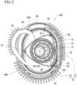
- Fig. 2 is a perspective plan view of the second side housing 50 of the rotary heat pump 100 according to an embodiment, and illustrates a state in which the internal structure of the rotary heat pump 100 is depicted.
- same configurations as those in the first embodiment are denoted by the same reference signs used in the example and detailed descriptions of the configurations are omitted herein.
- the rotary heat pump 100 according to the present embodiment is characterized by further having a bypass path 90 that communicates the two expansion regions 34 with each other, compared with the configurations described in the first embodiment. Furthermore, the rotary heat pump 100 differs from the rotary heat pump 100 according to the first embodiment in that each of a series of heat dissipation fins 72 and a series of heat absorption fin 74 are provided upright in one location and that the heat insulation portions 80 are provided only in two locations.
- the bypass path 90 is coupled to bypass holes 34A penetrating the rotary housing 30 in the expansion regions 34, respectively.
- the heat absorption fins 74 are provided upright only on the outer wall surface of the rotary housing 30 corresponding to the expansion region 34 provided right after the compression region 32.
- the expansion region 34 (expansion region 34 located right before the compression region 32 that is the high-temperature region) communicated with the above expansion region 34 by the bypass path 90 may be entirely formed in the heat insulation portion 80.
- a bypass path heat sink 92 can be provided on the bypass path 90.
- helium is not substantially compressed in the compression region 32 at a position put between the expansion regions 34 that are brought into communication by the bypass path 90 in the rotary heat pump 100 according to the present embodiment, so that this part is not provided with the heat dissipation fins 72 or the heat insulation portion 80.
- the number of the heat dissipation fins 72, the heat absorption fins 74, and the heat insulation portions 80 to be provided can be reduced, so that it is conveniently possible to contribute to further miniaturization, weight reduction, and manufacturing cost reduction of the rotary heat pump 100.
- the bypass holes 34A are provided in the rotary housing 30 in the expansion regions 34 and the bypass path 90 is coupled with the bypass holes 34A; however, the present invention is not limited to this form.
- the rotary heat pump 100 can have a form in which the bypass holes 34A passing through the first side housing 40 in a thickness direction are provided as an alternative to the bypass holes 34A provided in the rotary housing 30, and in which the bypass holes 34A in a plurality of expansion regions 34 are coupled together by the bypass path 90.
- These bypass holes 34A can also be provided in the second side housing 50 instead of the first side housing 40, or can be provided in both the first side housing 40 and the second side housing 50.
- bypass path heat sink 92 is provided on the bypass path 90 and in which heat exchange (heat absorption) can be also performed in the bypass path 90
- the bypass path 90 can be formed from a heat insulating material or a form in which the bypass path heat sink 92 is not provided can be employed.
- helium with high heat conductivity is filled into the rotary drive section 60 as the refrigerant
- the refrigerant with such properties is not limited to helium and a well-known refrigerant such as hydrogen or carbon dioxide can be used as appropriate.
- FIG. 4 there is also an invention as an air conditioner 200 equipped with the rotary heat pump 100 described above.
- FIG. 5 there is also an invention of an automobile 300 to which the air conditioner 200 equipped with the rotary heat pump 100 described in the present embodiments is attached. Since specific configurations of the air conditioner 200 and the automobile 300 are well known, detailed descriptions thereof are omitted herein.
- the air conditioner 200 according to the present invention can realize miniaturization, weight reduction, and high efficiency.
- the automobile 300 according to the present invention can not only realize the miniaturization and the weight reduction but also accelerate electrification of the automobile 300 by greatly saving energy.
- a form in which the rotary heat pumps 100 described above are disposed in series in an axial direction of the rotary shaft 10 can be employed. This results in an increase in an occupied volume of the rotary heat pumps 100; however, if a long and thin space can be allocated, it is possible to provide the rotary heat pump 100 with a higher performance and the air conditioner 200 and the automobile 300 each equipped with this rotary heat pump 100.
Landscapes
- Engineering & Computer Science (AREA)
- Mechanical Engineering (AREA)
- General Engineering & Computer Science (AREA)
- Chemical & Material Sciences (AREA)
- Combustion & Propulsion (AREA)
- Physics & Mathematics (AREA)
- Thermal Sciences (AREA)
- Applications Or Details Of Rotary Compressors (AREA)
- Rotary Pumps (AREA)
- Details And Applications Of Rotary Liquid Pumps (AREA)
Description
- The present invention relates to a rotary heat pump, and an air conditioner and an automobile each equipped with the same.
- Configurations of a heat pump (refrigerator) employing a Stirling engine type have been conventionally widely known. While a so-called reciprocating heat pump and a rotary heat pump are proposed as the heat pump of this type, it is said that the rotary heat pump is more suited than the reciprocating heat pump since being easier to achieve noise reduction and miniaturization. As recent rotary heat pumps, a rotary heat pump configured as disclosed in
JP 2008-38879 A -
JP H02 118363A WO 2010/125375 A2 discloses a unitary rotor side-seal member arranged to be coupled to a flank of a rotor of a rotary engine.US 2004/200217 A1 refers to a rotary engine, comprising a stator that includes a bladed heat transfer stator segment comprising an outer surface comprising a plurality of blades creating a flowpath on the outer surface.US 3,867,815 A discloses a heat engine which operates generally on the basis of the Carnot cycle and includes a rotor mounted within a chamber and sealed relative to the chamber by means of a plurality of radiating vanes. - As illustrated in
Fig. 6 , a rotary heat pump RHP disclosed inJP 2008-38879 A JP 2008-38879 A - Furthermore, rapid electrification has been recently underway at the level of laws and regulations in the automobile industry. However, energy densities of current batteries insufficiently meet demanded power of vehicle-mounted systems typified by, for example, a power controller, a drive system, a preventive safety device, and an in-vehicle air-conditioning system mounted in automobiles. Owing to this, efficiency improvement is adamantly demanded for all of these vehicle-mounted systems. The air conditioner that serves as the in-vehicle air conditioning system, in particular, has high power consumption and it may be said that the improvement in the efficiency of the air conditioner is a challenge to be solved as soon as possible in the electrification of automobiles.
- Therefore, an object of the present invention is to provide a rotary heat pump capable of realizing further miniaturization, weight reduction and efficiency improvement, compared with a current status, an air conditioner equipped with this rotary heat pump, and an automobile capable of accelerating electrification.
- The invention is defined in the independent claims. The dependent claims describe optional embodiments of the invention.
- A rotary heat pump, includes: a rotary drive section including: a rotary shaft; a stationary gear into which the rotary shaft is inserted; a rotor that has a rotor gear formed to have larger diameter dimensions than outside diameter dimensions of the stationary gear and engaged with the stationary gear, and that makes an eccentric rotation as the rotary shaft rotates; a rotary housing formed to be capable of demarcating a radially outward region of the rotor along a peritrochoid curve defined by the eccentric rotation of the rotor; a first side housing that has an insertion hole for inserting the rotary shaft, that covers one end side of the rotary housing, and that fixes the stationary gear; and a second side housing that covers an other end side of the rotary housing; a heat exchange fin provided on an outer surface of the rotary housing in each of a compression region where a region demarcated by an outer circumferential surface of the rotor and an inner circumferential surface of the rotary housing has a smallest planar area and an expansion region where the region has the largest planar area; and a bypass path that communicates a plurality of the expansion regions with one another.
- With this invention, heat dissipation and heat absorption can be performed in one rotary structure, so that it is possible to greatly reduce a size, reduce a weight, and improve efficiency of the rotary heat pump, compared with a conventional rotary heat pump.
- Furthermore, it is preferable that the bypass path is coupled with a bypass hole formed in at least one of the first side housing and the second side housing in the expansion region.
- It is thereby possible to prevent an increase in outer dimensions due to the bypass path.
- It is further preferable that the rotor and the rotary housing are a Wankel rotor and a Wankel rotary housing.
- It is thereby possible to employ a widely-known rotary structure, so that reliability of the rotary structure can be enhanced.
- Furthermore, there is an invention as an air conditioner equipped with the rotary heat pump according to any one of the above and also an invention of an automobile to which this air conditioner is mounted.
- These inventions can contribute to miniaturization, weight reduction, and high efficiency of the air conditioner. Furthermore, these inventions can contribute to miniaturization and weight reduction of the automobile equipped with such an air conditioner. In addition, energy saving of the vehicle-mounted systems allows for acceleration of electrification of the automobile.
- With configurations of the rotary heat pump according to the present invention, rotary structure sections can be integrated into one part, so that it is possible greatly reduce the size, reduce the weight, and improve efficiency, compared with the rotary heat pump according to the conventional technique. In addition, it is possible to reduce the size, reduce the weight, and improve the efficiency of the air conditioner equipped with this rotary heat pump. Furthermore, by being equipped with this air conditioner, it is possible to reduce the size and the weight of the automobile and to accelerate the electrification of the automobile.
-
-
Fig. 1 is a plan view illustrating an internal structure of a rotary heat pump according to an example useful to understand the invention with a perspective view of a second side housing thereof. -
Fig. 2 is a plan view illustrating an internal structure of a rotary heat pump according to an embodiment with a perspective view of a second side housing thereof. -
Fig. 3 is an explanatory diagram illustrating an internal structure of a rotary heat pump according to a modification of the embodiment with a perspective view of a second side housing thereof. -
Fig. 4 is a schematic diagram illustrating an air conditioner equipped with the rotary heat pump according to the present embodiments. -
Fig. 5 is an explanatory diagram illustrating an automobile to which the air conditioner illustrated inFig. 4 is attached. -
Fig. 6 is a schematic configuration diagram of a rotary heat pump according to a conventional technique. - A
rotary heat pump 100 according to the present invention will be described hereinafter with reference to the drawings. -
Fig. 1 is a plan view illustrating an internal structure of therotary heat pump 100 according to an example with a perspective view of asecond side housing 50. Therotary heat pump 100 includes arotary drive section 60 andheat exchange fins 70 provided on an outer wall surface of therotary drive section 60. Therotary drive section 60 in the present embodiment has arotary shaft 10, astationary gear 15, arotor 20, arotary housing 30, afirst side housing 40, and thesecond side housing 50. A structure of thisrotary drive section 60 is such that parts formed from a metal material andheat insulation portions 80 that are parts formed from a heat insulating material are alternately disposed in a circumferential direction. As is obvious fromFig. 1 , in the present embodiment, a form that employs a Wankelrotary drive section 60 in therotary heat pump 100 will be described. - A first end portion of the
rotary shaft 10 is rotatably supported in an internal space of therotary drive section 60, while a second end portion thereof projects outside of therotary drive section 60 from an insertion hole (not illustrated) of thefirst side housing 40. The second end portion of therotary shaft 10 is coupled with an output shaft of a prime mover provided outside of the rotary drive section 60 (note that neither the prime mover nor the output shaft is illustrated) by a well-known scheme. Furthermore, thestationary gear 15 which is inserted from an outer surface side of thefirst side housing 40 and through which therotary shaft 10 is inserted is fixedly screwed into the insertion hole of thefirst side housing 40. As such arotary shaft 10, an eccentric shaft is suitably used as in the case of a rotary engine. - At least a required thickness range of an outer surface of the
rotor 20 in the present example is formed into an outer shape of a so-called Reuleaux triangle (Wankel rotor) by a heat insulating material, and afitting hole 22 of therotor 20 is fitted into arotary journal 12 formed in therotary shaft 10 so that therotor 20 is fixed in a state of being rotatable together with therotary shaft 10. In a plan view of therotor 20, arotor gear 24 that has larger diameter dimensions than outside diameter dimensions of thestationary gear 15 and thefitting hole 22, that is formed on the same axis as thefitting hole 22, and that is engaged with thestationary gear 15 is formed in a central portion of therotor 20. Thestationary gear 15 and therotor gear 24 fixed to thefirst side housing 40 are engaged with each other only in a required range in the circumferential direction. Therefore, when therotary shaft 10 rotates, therotor 20 makes a motion of an eccentric rotation around the rotary shaft 10 (stationary gear 15). - The
rotary housing 30 is formed into a cocoon-shaped cylindrical body (Wankel rotary housing) that can planarly demarcate a radially outward region of therotor 20 along a peritrochoid curve defined by the eccentric rotation of therotor 20. One opening surface of therotary housing 30 is covered with thefirst side housing 40 in which the insertion hole (not illustrated) for inserting thestationary gear 15 into an interior of the rotary housing 30 (rotary drive section 60) is formed. Therotary shaft 10 is inserted into thestationary gear 15, and therotary shaft 10, thestationary gear 15, and thefirst side housing 40 are sealed by a well-known scheme. - Moreover, the
second side housing 50 is mounted to the other opening surface of therotary housing 30 in a state of being sealed with therotary housing 30. Basic configurations of such arotary drive section 60 can be designed similar to configurations of a so-called rotary engine from which intake/exhaust sections and an ignition sections are excluded. In the present embodiment, it is preferable that spaces surrounded by therotor 20, therotary housing 30, thefirst side housing 40, and thesecond side housing 50 are sealed with seal members (not illustrated) provided appropriately. Each of the spaces is filled with helium that is an example of a refrigerant. - Furthermore, the
heat exchange fins 70 are provided in a plurality of circumferential locations each over a required range on an outer surface of therotary housing 30. In the circumferential direction of therotary housing 30, a shape and a planar area of a region demarcated by an inner circumferential surface of therotary housing 30 and an outer circumferential surface of therotor 20 vary with the eccentric rotation of therotor 20. In the present embodiment, when therotary shaft 10 is set as a rotation center, twocompression regions 32 where a demarcated region has a smallest planar area and twoexpansion regions 34 where the demarcated region has a largest planar area are formed, and thecompression areas 32 and theexpansion region 34 are alternately disposed at intervals of 90 degrees in the circumferential direction of therotary housing 30 with a planar central portion of therotary housing 30 assumed as a rotation center. - Out of the
heat exchange fins 70, the fins provided upright on the outer wall surface of therotary drive section 60 at positions corresponding to thecompression regions 32 that are high-temperature regions areheat dissipation fins 72 and the fins provided upright on the outer wall surface of therotary drive section 60 at positions corresponding to theexpansion regions 34 that are low-temperature regions areheat absorption fins 74. - When the
rotary drive section 60 in the present example is driven to rotate by the prime mover, helium that is the refrigerant and that is filled in the internal space of therotary drive section 60 is sequentially fed to thecompression regions 32 and theexpansion regions 34 that appear alternately in the circumferential direction of therotary housing 30 to switch over between a high-temperature state and a low-temperature state. Furthermore, in the present example, required range portions including at least boundaries between thecompression regions 32 and theexpansion regions 34 in the circumferential direction of therotary housing 30, thefirst side housing 40, and thesecond side housing 50 are formed from the heat insulating material, and the heat insulating material portions serve as theheat insulation portions 80. Disposing suchheat insulation portions 80 in boundary portions between thecompression regions 32 and theexpansion regions 34 enables even the single-rotor typerotary drive section 60 to exchange heat with outside air to be subjected to heat exchange in theheat dissipation fins 72 and theheat absorption fins 74. It is noted that thefirst side housing 40 and thesecond side housing 50 according to the present embodiment are entirely formed from the heat insulating material. - By employing the form of the
rotary heat pump 100 according to the present embodiment, a fully gas phase Carnot cycle heat pump structure can be provided. While therotor 20 according to the present embodiment rotates once in an internal space of therotary housing 30, each of heat dissipation and heat absorption can be performed twice. These operations can ensure efficient heat exchange while ensuring small-sized, lightweight configurations and low noise. In addition, by accelerating the rotation of the output shaft of the prime mover to increase a revolving speed of therotor 20, rapid heating and rapid cooling can be conveniently ensured. -
Fig. 2 is a perspective plan view of thesecond side housing 50 of therotary heat pump 100 according to an embodiment, and illustrates a state in which the internal structure of therotary heat pump 100 is depicted. In the present embodiment, same configurations as those in the first embodiment are denoted by the same reference signs used in the example and detailed descriptions of the configurations are omitted herein. - The
rotary heat pump 100 according to the present embodiment is characterized by further having abypass path 90 that communicates the twoexpansion regions 34 with each other, compared with the configurations described in the first embodiment. Furthermore, therotary heat pump 100 differs from therotary heat pump 100 according to the first embodiment in that each of a series ofheat dissipation fins 72 and a series ofheat absorption fin 74 are provided upright in one location and that theheat insulation portions 80 are provided only in two locations. - The
bypass path 90 according to the present embodiment is coupled to bypassholes 34A penetrating therotary housing 30 in theexpansion regions 34, respectively. By communicating the twoexpansion regions 34 with each other in this way, it is possible to greatly increase a volume of eachexpansion region 34 continuous with thecompression region 32 and promote a fall in temperature due to expansion of helium. While the twoexpansion regions 34 are brought into communication in the present embodiment, theheat absorption fins 74 are provided upright only on the outer wall surface of therotary housing 30 corresponding to theexpansion region 34 provided right after thecompression region 32. Furthermore, the expansion region 34 (expansion region 34 located right before thecompression region 32 that is the high-temperature region) communicated with theabove expansion region 34 by thebypass path 90 may be entirely formed in theheat insulation portion 80. Moreover, as illustrated inFig. 2 , a bypasspath heat sink 92 can be provided on thebypass path 90. - Moreover, helium is not substantially compressed in the
compression region 32 at a position put between theexpansion regions 34 that are brought into communication by thebypass path 90 in therotary heat pump 100 according to the present embodiment, so that this part is not provided with theheat dissipation fins 72 or theheat insulation portion 80. As described above, in therotary heat pump 100 according to the present embodiment, the number of theheat dissipation fins 72, theheat absorption fins 74, and theheat insulation portions 80 to be provided can be reduced, so that it is conveniently possible to contribute to further miniaturization, weight reduction, and manufacturing cost reduction of therotary heat pump 100. - As described above, the
rotary heat pump 100 according to the present invention has been described on the basis of the embodiments; however, the present invention is not limited to the above embodiments. For example, the form in which therotary heat pump 100 according to the embodiments described above employs the Wankelrotary drive section 60 has been described; however, the present invention is not limited to this structure and a structure of a well-knownrotary drive section 60 can be applied as appropriate. Whenmany expansion regions 34 are present in the structure of therotary drive section 60, a plurality of, i.e., three ormore expansion regions 34 may be communicated with one another by thebypass path 90. It is thereby possible to provide expansion areas formed from the plurality ofexpansion regions 34 in a plurality of locations in the circumferential direction of therotary drive section 60. - Furthermore, as illustrated in
Fig. 2 , in therotary heat pump 100 according to the second embodiment, the bypass holes 34A are provided in therotary housing 30 in theexpansion regions 34 and thebypass path 90 is coupled with the bypass holes 34A; however, the present invention is not limited to this form. As illustrated inFig. 3 , therotary heat pump 100 can have a form in which the bypass holes 34A passing through thefirst side housing 40 in a thickness direction are provided as an alternative to thebypass holes 34A provided in therotary housing 30, and in which the bypass holes 34A in a plurality ofexpansion regions 34 are coupled together by thebypass path 90. These bypass holes 34A can also be provided in thesecond side housing 50 instead of thefirst side housing 40, or can be provided in both thefirst side housing 40 and thesecond side housing 50. By providing thebypass path 90 within a planar region of therotary drive section 60 in this way, it is conveniently possible to reduce an area of thebypass path 90 that occupies the plane, compared with therotary heat pump 100 according to the second embodiment. - Similarly, while the form in which the bypass
path heat sink 92 is provided on thebypass path 90 and in which heat exchange (heat absorption) can be also performed in thebypass path 90 is described in the second embodiment, the present invention is not limited to this form. Thebypass path 90 can be formed from a heat insulating material or a form in which the bypasspath heat sink 92 is not provided can be employed. - Moreover, the form in which helium with high heat conductivity is filled into the
rotary drive section 60 as the refrigerant is described in the present embodiments; however, the refrigerant with such properties is not limited to helium and a well-known refrigerant such as hydrogen or carbon dioxide can be used as appropriate. - Furthermore, as illustrated in
Fig. 4 , there is also an invention as anair conditioner 200 equipped with therotary heat pump 100 described above. Moreover, as illustrated inFig. 5 , there is also an invention of anautomobile 300 to which theair conditioner 200 equipped with therotary heat pump 100 described in the present embodiments is attached. Since specific configurations of theair conditioner 200 and theautomobile 300 are well known, detailed descriptions thereof are omitted herein. Theair conditioner 200 according to the present invention can realize miniaturization, weight reduction, and high efficiency. In addition, theautomobile 300 according to the present invention can not only realize the miniaturization and the weight reduction but also accelerate electrification of theautomobile 300 by greatly saving energy. - Furthermore, a form in which the
rotary heat pumps 100 described above are disposed in series in an axial direction of therotary shaft 10 can be employed. This results in an increase in an occupied volume of therotary heat pumps 100; however, if a long and thin space can be allocated, it is possible to provide therotary heat pump 100 with a higher performance and theair conditioner 200 and theautomobile 300 each equipped with thisrotary heat pump 100. - Moreover, forms in which the modification described in the specification or other well-known configurations are combined with the configurations in the present embodiments described so above can be employed.
Claims (5)
- A rotary heat pump (100), comprising:a rotary drive section (60) including: a rotary shaft (10); a stationary gear (15) into which the rotary shaft (10) is inserted; a rotor (20) that has a rotor gear (24) formed to have larger diameter dimensions than outside diameter dimensions of the stationary gear (15) and engaged with the stationary gear (15), and that makes an eccentric rotation as the rotary shaft (10) rotates; a rotary housing (30) formed to be capable of demarcating a radially outward region of the rotor (20) along a peritrochoid curve defined by the eccentric rotation of the rotor (20); a first side housing (40) that has an insertion hole for inserting the rotary shaft (10), that covers one end side of the rotary housing (30), and that fixes the stationary gear (15); and a second side housing (50) that covers an other end side of the rotary housing (30);characterized by heat exchange fins (70) provided on an outer surface of the rotary housing (30) in a compression region (32) where a region demarcated by an outer circumferential surface of the rotor (20) and an inner circumferential surface of the rotary housing (30) has a smallest planar area and an expansion region (34) where the region has the largest planar area; anda bypass path (90) that communicates a plurality of the expansion regions (34) with one another, whereinthe heat exchange fins (70) include heat absorption fins (74) provided to the expansion region (34) on an upstream side among two of the expansion regions (34) communicated one another by the bypass path (90), and heat dissipation fins (72) provided to the compression region (32) located right after the expansion region (34) on a downstream side among the expansion regions (34) communicated one another by the bypass path (90), anda bypass path heat sink (92) is provided on the bypass path (90).
- The rotary heat pump (100) according to claim 1, wherein
the bypass path (90) is coupled with a bypass hole (34A) formed in at least one of the first side housing (40) and the second side housing (50) in the expansion region (34). - The rotary heat pump (100) according to claim 1 or 2, wherein
the rotor (20) and the rotary housing (30) are a Wankel rotor and a Wankel rotary housing. - An air conditioner (200) equipped with the rotary heat pump (100) according to any one of claims 1 to 3.
- An automobile (300) to which the air conditioner (200) according to claim 4 is attached.
Applications Claiming Priority (1)
| Application Number | Priority Date | Filing Date | Title |
|---|---|---|---|
| PCT/JP2021/000690 WO2022153364A1 (en) | 2021-01-12 | 2021-01-12 | Rotary heat pump, and air conditioner and automobile equipped with same |
Publications (3)
| Publication Number | Publication Date |
|---|---|
| EP4112938A1 EP4112938A1 (en) | 2023-01-04 |
| EP4112938A4 EP4112938A4 (en) | 2023-07-19 |
| EP4112938B1 true EP4112938B1 (en) | 2025-06-25 |
Family
ID=80629614
Family Applications (1)
| Application Number | Title | Priority Date | Filing Date |
|---|---|---|---|
| EP21919260.6A Active EP4112938B1 (en) | 2021-01-12 | 2021-01-12 | Rotary heat pump, and air conditioner and automobile equipped with same |
Country Status (6)
| Country | Link |
|---|---|
| US (1) | US11988166B2 (en) |
| EP (1) | EP4112938B1 (en) |
| JP (1) | JP7007776B1 (en) |
| KR (1) | KR102799855B1 (en) |
| CN (1) | CN115443380B (en) |
| WO (2) | WO2022153364A1 (en) |
Families Citing this family (4)
| Publication number | Priority date | Publication date | Assignee | Title |
|---|---|---|---|---|
| WO2024053075A1 (en) * | 2022-09-09 | 2024-03-14 | 丸子警報器株式会社 | Driving system equipment cooling device for electric mobile body |
| JP7549382B2 (en) * | 2022-12-27 | 2024-09-11 | 丸子警報器株式会社 | Rotary drive unit and rotary heat pump |
| WO2025046833A1 (en) * | 2023-08-31 | 2025-03-06 | 三菱電機ビルソリューションズ株式会社 | Elevator system |
| DE102024203305A1 (en) * | 2024-04-11 | 2025-10-16 | Zf Friedrichshafen Ag | Cycle process device, axle assembly, vehicle and process |
Family Cites Families (14)
| Publication number | Priority date | Publication date | Assignee | Title |
|---|---|---|---|---|
| US3042009A (en) * | 1958-10-02 | 1962-07-03 | Nsu Motorenwerke Ag | Cooling arrangement for rotary mechanisms |
| BE789541A (en) | 1970-11-04 | 1973-01-15 | Barrett George M | LOW POLLUTION THERMAL ENGINE |
| US4357800A (en) * | 1979-12-17 | 1982-11-09 | Hecker Walter G | Rotary heat engine |
| JPH02118363A (en) | 1988-10-28 | 1990-05-02 | Mazda Motor Corp | Heat pump device |
| JPH03117658A (en) | 1989-09-29 | 1991-05-20 | Mazda Motor Corp | External combustion type rotary piston engine |
| CN100398829C (en) * | 2002-11-26 | 2008-07-02 | 乐金电子(天津)电器有限公司 | Antiwear structure for preventing wankle compressor |
| US20040200217A1 (en) | 2003-04-08 | 2004-10-14 | Marchetti George A | Bladed heat transfer stator elements for a stirling rotary engine |
| EP1942265B1 (en) | 2005-09-06 | 2011-08-24 | Da Vinci Co., Ltd. | Rotary heat engine |
| JP2008038879A (en) | 2006-08-03 | 2008-02-21 | Teratekku:Kk | Rotary Stirling engine |
| EP2322760A4 (en) * | 2008-08-01 | 2012-03-21 | Da Vinci Co Ltd | ROTARY MOTOR OF WANKEL TYPE |
| GB2482096A (en) | 2009-04-27 | 2012-01-18 | Ip Consortium Ltd | Rotor side seal and method of sealing a rotor |
| FR2961266B1 (en) * | 2010-06-11 | 2015-07-17 | Bernard Macarez | ENGINE THERMAL HEAD EXCHANGER |
| US20160305315A1 (en) * | 2014-03-14 | 2016-10-20 | National Chung_Shan Institute Of Science And Technology | External cooling fin for rotary engine |
| US20150260091A1 (en) * | 2014-03-14 | 2015-09-17 | Chung-Shan Institute Of Science And Technology, Armaments Bureau, M.N.D | External cooling fin for rotary engine |
-
2021
- 2021-01-12 EP EP21919260.6A patent/EP4112938B1/en active Active
- 2021-01-12 WO PCT/JP2021/000690 patent/WO2022153364A1/en not_active Ceased
- 2021-01-12 US US18/017,688 patent/US11988166B2/en active Active
- 2021-01-12 JP JP2021517497A patent/JP7007776B1/en active Active
- 2021-01-12 KR KR1020227035222A patent/KR102799855B1/en active Active
- 2021-01-12 CN CN202180029858.9A patent/CN115443380B/en active Active
- 2021-12-06 WO PCT/JP2021/044696 patent/WO2022153714A1/en not_active Ceased
Also Published As
| Publication number | Publication date |
|---|---|
| CN115443380A (en) | 2022-12-06 |
| WO2022153714A1 (en) | 2022-07-21 |
| WO2022153364A1 (en) | 2022-07-21 |
| CN115443380B (en) | 2025-08-26 |
| KR20220148288A (en) | 2022-11-04 |
| KR102799855B1 (en) | 2025-04-29 |
| JP7007776B1 (en) | 2022-01-25 |
| JPWO2022153364A1 (en) | 2022-07-21 |
| US20230279824A1 (en) | 2023-09-07 |
| EP4112938A4 (en) | 2023-07-19 |
| EP4112938A1 (en) | 2023-01-04 |
| US11988166B2 (en) | 2024-05-21 |
Similar Documents
| Publication | Publication Date | Title |
|---|---|---|
| EP4112938B1 (en) | Rotary heat pump, and air conditioner and automobile equipped with same | |
| EP1209362B1 (en) | Hermetic compressors | |
| JP3818213B2 (en) | Electric compressor | |
| US7735335B2 (en) | Fluid pump having expansion device and rankine cycle using the same | |
| US7147443B2 (en) | Electric compressor | |
| US6503069B2 (en) | Scroll-type compressor with an integrated motor and a compact cooling system | |
| CN102844528A (en) | Waste heat utilization system for internal combustion engine, and motor-generator device for use in the system | |
| KR20100128300A (en) | Rotary piston internal combustion engine power unit | |
| US7179068B2 (en) | Electric compressor | |
| EP1227244B1 (en) | Scroll type compressor | |
| CN111306062A (en) | Rotary compressor for vehicle and vehicle with same | |
| CN206206161U (en) | Dual drive compressor | |
| JP2012132435A (en) | Air conditioner | |
| CN116420014B (en) | Rotary heat pump, and air conditioner and automobile equipped with same | |
| CN107842499A (en) | Dual drive compressor | |
| JP7818306B2 (en) | Cooling device for drivetrain equipment of electric vehicles | |
| CN109838381B (en) | Scroll compressor having a plurality of scroll members | |
| CN107842501A (en) | Compressor | |
| CN113294237A (en) | Rotor piston engine | |
| JP4104534B2 (en) | Hermetic compressor | |
| JP2013072411A (en) | Electric compressor | |
| CN213088117U (en) | Embedded motor suitable for small-size turbine engine | |
| JP2007002705A (en) | Electric compressor | |
| JP2005054585A (en) | Compression/expansion machine |
Legal Events
| Date | Code | Title | Description |
|---|---|---|---|
| STAA | Information on the status of an ep patent application or granted ep patent |
Free format text: STATUS: THE INTERNATIONAL PUBLICATION HAS BEEN MADE |
|
| PUAI | Public reference made under article 153(3) epc to a published international application that has entered the european phase |
Free format text: ORIGINAL CODE: 0009012 |
|
| STAA | Information on the status of an ep patent application or granted ep patent |
Free format text: STATUS: REQUEST FOR EXAMINATION WAS MADE |
|
| 17P | Request for examination filed |
Effective date: 20220930 |
|
| AK | Designated contracting states |
Kind code of ref document: A1 Designated state(s): AL AT BE BG CH CY CZ DE DK EE ES FI FR GB GR HR HU IE IS IT LI LT LU LV MC MK MT NL NO PL PT RO RS SE SI SK SM TR |
|
| REG | Reference to a national code |
Ref legal event code: R079 Ipc: F01C0001220000 Ref country code: DE Ref legal event code: R079 Ref document number: 602021033106 Country of ref document: DE Free format text: PREVIOUS MAIN CLASS: F04C0018220000 Ipc: F01C0001220000 |
|
| A4 | Supplementary search report drawn up and despatched |
Effective date: 20230621 |
|
| RIC1 | Information provided on ipc code assigned before grant |
Ipc: F01C 1/22 20060101AFI20230615BHEP |
|
| DAV | Request for validation of the european patent (deleted) | ||
| DAX | Request for extension of the european patent (deleted) | ||
| GRAP | Despatch of communication of intention to grant a patent |
Free format text: ORIGINAL CODE: EPIDOSNIGR1 |
|
| STAA | Information on the status of an ep patent application or granted ep patent |
Free format text: STATUS: GRANT OF PATENT IS INTENDED |
|
| INTG | Intention to grant announced |
Effective date: 20250227 |
|
| GRAS | Grant fee paid |
Free format text: ORIGINAL CODE: EPIDOSNIGR3 |
|
| GRAA | (expected) grant |
Free format text: ORIGINAL CODE: 0009210 |
|
| STAA | Information on the status of an ep patent application or granted ep patent |
Free format text: STATUS: THE PATENT HAS BEEN GRANTED |
|
| P01 | Opt-out of the competence of the unified patent court (upc) registered |
Free format text: CASE NUMBER: APP_19890/2025 Effective date: 20250425 |
|
| AK | Designated contracting states |
Kind code of ref document: B1 Designated state(s): AL AT BE BG CH CY CZ DE DK EE ES FI FR GB GR HR HU IE IS IT LI LT LU LV MC MK MT NL NO PL PT RO RS SE SI SK SM TR |
|
| REG | Reference to a national code |
Ref country code: GB Ref legal event code: FG4D |
|
| REG | Reference to a national code |
Ref country code: CH Ref legal event code: EP |
|
| REG | Reference to a national code |
Ref country code: CH Ref legal event code: EP |
|
| REG | Reference to a national code |
Ref country code: IE Ref legal event code: FG4D |
|
| REG | Reference to a national code |
Ref country code: DE Ref legal event code: R096 Ref document number: 602021033106 Country of ref document: DE |
|
| PG25 | Lapsed in a contracting state [announced via postgrant information from national office to epo] |
Ref country code: FI Free format text: LAPSE BECAUSE OF FAILURE TO SUBMIT A TRANSLATION OF THE DESCRIPTION OR TO PAY THE FEE WITHIN THE PRESCRIBED TIME-LIMIT Effective date: 20250625 |
|
| REG | Reference to a national code |
Ref country code: LT Ref legal event code: MG9D |
|
| PG25 | Lapsed in a contracting state [announced via postgrant information from national office to epo] |
Ref country code: NO Free format text: LAPSE BECAUSE OF FAILURE TO SUBMIT A TRANSLATION OF THE DESCRIPTION OR TO PAY THE FEE WITHIN THE PRESCRIBED TIME-LIMIT Effective date: 20250925 Ref country code: GR Free format text: LAPSE BECAUSE OF FAILURE TO SUBMIT A TRANSLATION OF THE DESCRIPTION OR TO PAY THE FEE WITHIN THE PRESCRIBED TIME-LIMIT Effective date: 20250926 |
|
| PG25 | Lapsed in a contracting state [announced via postgrant information from national office to epo] |
Ref country code: BG Free format text: LAPSE BECAUSE OF FAILURE TO SUBMIT A TRANSLATION OF THE DESCRIPTION OR TO PAY THE FEE WITHIN THE PRESCRIBED TIME-LIMIT Effective date: 20250625 |
|
| PG25 | Lapsed in a contracting state [announced via postgrant information from national office to epo] |
Ref country code: HR Free format text: LAPSE BECAUSE OF FAILURE TO SUBMIT A TRANSLATION OF THE DESCRIPTION OR TO PAY THE FEE WITHIN THE PRESCRIBED TIME-LIMIT Effective date: 20250625 |
|
| PG25 | Lapsed in a contracting state [announced via postgrant information from national office to epo] |
Ref country code: RS Free format text: LAPSE BECAUSE OF FAILURE TO SUBMIT A TRANSLATION OF THE DESCRIPTION OR TO PAY THE FEE WITHIN THE PRESCRIBED TIME-LIMIT Effective date: 20250925 |
|
| PG25 | Lapsed in a contracting state [announced via postgrant information from national office to epo] |
Ref country code: LV Free format text: LAPSE BECAUSE OF FAILURE TO SUBMIT A TRANSLATION OF THE DESCRIPTION OR TO PAY THE FEE WITHIN THE PRESCRIBED TIME-LIMIT Effective date: 20250625 |
|
| REG | Reference to a national code |
Ref country code: NL Ref legal event code: MP Effective date: 20250625 |
|
| PG25 | Lapsed in a contracting state [announced via postgrant information from national office to epo] |
Ref country code: NL Free format text: LAPSE BECAUSE OF FAILURE TO SUBMIT A TRANSLATION OF THE DESCRIPTION OR TO PAY THE FEE WITHIN THE PRESCRIBED TIME-LIMIT Effective date: 20250625 |
|
| PG25 | Lapsed in a contracting state [announced via postgrant information from national office to epo] |
Ref country code: PT Free format text: LAPSE BECAUSE OF FAILURE TO SUBMIT A TRANSLATION OF THE DESCRIPTION OR TO PAY THE FEE WITHIN THE PRESCRIBED TIME-LIMIT Effective date: 20251027 |
|
| REG | Reference to a national code |
Ref country code: AT Ref legal event code: MK05 Ref document number: 1806625 Country of ref document: AT Kind code of ref document: T Effective date: 20250625 |
|
| PG25 | Lapsed in a contracting state [announced via postgrant information from national office to epo] |
Ref country code: IS Free format text: LAPSE BECAUSE OF FAILURE TO SUBMIT A TRANSLATION OF THE DESCRIPTION OR TO PAY THE FEE WITHIN THE PRESCRIBED TIME-LIMIT Effective date: 20251025 |
|
| PG25 | Lapsed in a contracting state [announced via postgrant information from national office to epo] |
Ref country code: AT Free format text: LAPSE BECAUSE OF FAILURE TO SUBMIT A TRANSLATION OF THE DESCRIPTION OR TO PAY THE FEE WITHIN THE PRESCRIBED TIME-LIMIT Effective date: 20250625 Ref country code: SM Free format text: LAPSE BECAUSE OF FAILURE TO SUBMIT A TRANSLATION OF THE DESCRIPTION OR TO PAY THE FEE WITHIN THE PRESCRIBED TIME-LIMIT Effective date: 20250625 |
|
| PGFP | Annual fee paid to national office [announced via postgrant information from national office to epo] |
Ref country code: FR Payment date: 20251217 Year of fee payment: 6 |
|
| PG25 | Lapsed in a contracting state [announced via postgrant information from national office to epo] |
Ref country code: CZ Free format text: LAPSE BECAUSE OF FAILURE TO SUBMIT A TRANSLATION OF THE DESCRIPTION OR TO PAY THE FEE WITHIN THE PRESCRIBED TIME-LIMIT Effective date: 20250625 |
|
| PG25 | Lapsed in a contracting state [announced via postgrant information from national office to epo] |
Ref country code: PL Free format text: LAPSE BECAUSE OF FAILURE TO SUBMIT A TRANSLATION OF THE DESCRIPTION OR TO PAY THE FEE WITHIN THE PRESCRIBED TIME-LIMIT Effective date: 20250625 |
|
| PG25 | Lapsed in a contracting state [announced via postgrant information from national office to epo] |
Ref country code: EE Free format text: LAPSE BECAUSE OF FAILURE TO SUBMIT A TRANSLATION OF THE DESCRIPTION OR TO PAY THE FEE WITHIN THE PRESCRIBED TIME-LIMIT Effective date: 20250625 |
|
| PG25 | Lapsed in a contracting state [announced via postgrant information from national office to epo] |
Ref country code: SK Free format text: LAPSE BECAUSE OF FAILURE TO SUBMIT A TRANSLATION OF THE DESCRIPTION OR TO PAY THE FEE WITHIN THE PRESCRIBED TIME-LIMIT Effective date: 20250625 |
|
| PG25 | Lapsed in a contracting state [announced via postgrant information from national office to epo] |
Ref country code: ES Free format text: LAPSE BECAUSE OF FAILURE TO SUBMIT A TRANSLATION OF THE DESCRIPTION OR TO PAY THE FEE WITHIN THE PRESCRIBED TIME-LIMIT Effective date: 20250625 |
|
| PG25 | Lapsed in a contracting state [announced via postgrant information from national office to epo] |
Ref country code: DK Free format text: LAPSE BECAUSE OF FAILURE TO SUBMIT A TRANSLATION OF THE DESCRIPTION OR TO PAY THE FEE WITHIN THE PRESCRIBED TIME-LIMIT Effective date: 20250625 |
|
| PGFP | Annual fee paid to national office [announced via postgrant information from national office to epo] |
Ref country code: DE Payment date: 20251219 Year of fee payment: 6 |
|
| PG25 | Lapsed in a contracting state [announced via postgrant information from national office to epo] |
Ref country code: IT Free format text: LAPSE BECAUSE OF FAILURE TO SUBMIT A TRANSLATION OF THE DESCRIPTION OR TO PAY THE FEE WITHIN THE PRESCRIBED TIME-LIMIT Effective date: 20250625 |
|
| PLBE | No opposition filed within time limit |
Free format text: ORIGINAL CODE: 0009261 |
|
| STAA | Information on the status of an ep patent application or granted ep patent |
Free format text: STATUS: NO OPPOSITION FILED WITHIN TIME LIMIT |