EP4112912A1 - Combustion apparatus for rocket engine - Google Patents
Combustion apparatus for rocket engine Download PDFInfo
- Publication number
- EP4112912A1 EP4112912A1 EP21760050.1A EP21760050A EP4112912A1 EP 4112912 A1 EP4112912 A1 EP 4112912A1 EP 21760050 A EP21760050 A EP 21760050A EP 4112912 A1 EP4112912 A1 EP 4112912A1
- Authority
- EP
- European Patent Office
- Prior art keywords
- passage
- oxidant
- fuel
- rocket engine
- combustor
- Prior art date
- Legal status (The legal status is an assumption and is not a legal conclusion. Google has not performed a legal analysis and makes no representation as to the accuracy of the status listed.)
- Pending
Links
Images

Classifications
-
- F—MECHANICAL ENGINEERING; LIGHTING; HEATING; WEAPONS; BLASTING
- F02—COMBUSTION ENGINES; HOT-GAS OR COMBUSTION-PRODUCT ENGINE PLANTS
- F02K—JET-PROPULSION PLANTS
- F02K9/00—Rocket-engine plants, i.e. plants carrying both fuel and oxidant therefor; Control thereof
- F02K9/42—Rocket-engine plants, i.e. plants carrying both fuel and oxidant therefor; Control thereof using liquid or gaseous propellants
- F02K9/44—Feeding propellants
- F02K9/52—Injectors
-
- F—MECHANICAL ENGINEERING; LIGHTING; HEATING; WEAPONS; BLASTING
- F02—COMBUSTION ENGINES; HOT-GAS OR COMBUSTION-PRODUCT ENGINE PLANTS
- F02K—JET-PROPULSION PLANTS
- F02K9/00—Rocket-engine plants, i.e. plants carrying both fuel and oxidant therefor; Control thereof
- F02K9/97—Rocket nozzles
- F02K9/972—Fluid cooling arrangements for nozzles
-
- F—MECHANICAL ENGINEERING; LIGHTING; HEATING; WEAPONS; BLASTING
- F05—INDEXING SCHEMES RELATING TO ENGINES OR PUMPS IN VARIOUS SUBCLASSES OF CLASSES F01-F04
- F05D—INDEXING SCHEME FOR ASPECTS RELATING TO NON-POSITIVE-DISPLACEMENT MACHINES OR ENGINES, GAS-TURBINES OR JET-PROPULSION PLANTS
- F05D2240/00—Components
- F05D2240/35—Combustors or associated equipment
-
- F—MECHANICAL ENGINEERING; LIGHTING; HEATING; WEAPONS; BLASTING
- F05—INDEXING SCHEMES RELATING TO ENGINES OR PUMPS IN VARIOUS SUBCLASSES OF CLASSES F01-F04
- F05D—INDEXING SCHEME FOR ASPECTS RELATING TO NON-POSITIVE-DISPLACEMENT MACHINES OR ENGINES, GAS-TURBINES OR JET-PROPULSION PLANTS
- F05D2260/00—Function
- F05D2260/20—Heat transfer, e.g. cooling
- F05D2260/221—Improvement of heat transfer
- F05D2260/2214—Improvement of heat transfer by increasing the heat transfer surface
-
- F—MECHANICAL ENGINEERING; LIGHTING; HEATING; WEAPONS; BLASTING
- F05—INDEXING SCHEMES RELATING TO ENGINES OR PUMPS IN VARIOUS SUBCLASSES OF CLASSES F01-F04
- F05D—INDEXING SCHEME FOR ASPECTS RELATING TO NON-POSITIVE-DISPLACEMENT MACHINES OR ENGINES, GAS-TURBINES OR JET-PROPULSION PLANTS
- F05D2260/00—Function
- F05D2260/20—Heat transfer, e.g. cooling
- F05D2260/232—Heat transfer, e.g. cooling characterized by the cooling medium
-
- F—MECHANICAL ENGINEERING; LIGHTING; HEATING; WEAPONS; BLASTING
- F05—INDEXING SCHEMES RELATING TO ENGINES OR PUMPS IN VARIOUS SUBCLASSES OF CLASSES F01-F04
- F05D—INDEXING SCHEME FOR ASPECTS RELATING TO NON-POSITIVE-DISPLACEMENT MACHINES OR ENGINES, GAS-TURBINES OR JET-PROPULSION PLANTS
- F05D2260/00—Function
- F05D2260/96—Preventing, counteracting or reducing vibration or noise
-
- F—MECHANICAL ENGINEERING; LIGHTING; HEATING; WEAPONS; BLASTING
- F05—INDEXING SCHEMES RELATING TO ENGINES OR PUMPS IN VARIOUS SUBCLASSES OF CLASSES F01-F04
- F05D—INDEXING SCHEME FOR ASPECTS RELATING TO NON-POSITIVE-DISPLACEMENT MACHINES OR ENGINES, GAS-TURBINES OR JET-PROPULSION PLANTS
- F05D2260/00—Function
- F05D2260/96—Preventing, counteracting or reducing vibration or noise
- F05D2260/964—Preventing, counteracting or reducing vibration or noise counteracting thermoacoustic noise
Definitions
- the present disclosure relates to a combustor for a rocket engine.
- Patent Document 1 discloses a thrust control apparatus and a thrust control method for a liquid rocket engine.
- the purpose of the thrust control apparatus and thrust control method is to reduce the possibility of generating low-frequency combustion vibration (chugging) caused by an extreme decrease in injection differential pressure (a difference between an injection pressure and a combustion pressure) when operating in a reduced thrust range by controlling a thrust to be reduced in the thrust control of a rocket engine.
- a temperature control means for controlling the temperature of the liquid propellant at an upstream side of the injection orifice is provided and the temperature of the liquid propellant is raised so as to secure an injection differential pressure needed for reduction control using a saturated vapor pressure of the liquid propellant when controlling the thrust of the engine to be reduced.
- Patent Document 1 Japanese Unexamined Patent Application, First Publication No. 2013-155655
- vibration can be suppressed in a single thrust (operating point) by changing a shape of an injection orifice, but vibration cannot be suppressed in a plurality of thrusts.
- a combustor for a reusable rocket engine is used in a relatively wide thrust range for a landing operation and the like. Therefore, in the liquid rocket engine described in Patent Document 1, the vibration of the combustor for the reusable rocket engine cannot be effectively suppressed over an entire thrust range.
- the present disclosure has been made in view of the above circumstances, and an object of the present disclosure is to provide a combustor for a rocket engine capable of effectively suppressing vibration when operating with a plurality of thrusts.
- a combustor for a rocket engine includes a combustion room configured to cause a combustion reaction between a fuel and an oxidant, an injector configured to inject the fuel and the oxidant into the combustion room, a nozzle skirt configured to inject combustion gas generated by the combustion reaction to an outside, and an inertance increasing portion configured to increase an equivalent inertance in a vibration equivalent circuit of the combustor for the rocket engine.
- the combustor for the rocket engine according to a second aspect of the present disclosure may further include, in the first aspect described above, a fuel passage configured to guide the fuel to the combustion room, and an oxidant passage configured to guide the oxidant to the combustion room, in which the inertance increasing portion increases the equivalent inertance by providing a plurality of branch portions in the fuel passage or/and the oxidant passage to lengthen a passage length thereof.
- the inertance increasing portion may branch the fuel passage or/and the oxidant passage without changing a passage cross-sectional area in front of and behind the branch portion.
- the fuel passage or/and the oxidant passage may include a cooling passage configured to cool the nozzle skirt, and in the inertance increasing portion, the plurality of branch portions are provided in front of the cooling passage.
- the cooling passage may be provided from a base end to an end portion of the nozzle skirt and folded back at the end portion.
- the cooling passage may be spirally provided with respect to the nozzle skirt.
- a combustor for a rocket engine capable of effectively suppressing vibration when operating with a plurality of thrusts.
- a combustor C for a rocket engine according to the present embodiment is a combustor constituting a reusable rocket engine. That is, unlike a combustor for a disposable rocket in the related art, the combustor C for the rocket engine is a combustor that operates with a plurality of thrusts (operating points) in a wide range, that is, operates even with a thrust (low operating point) that is significantly lower than a normal thrust, in addition to the normal thrust (normal operating point).
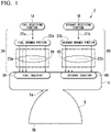
- the combustor C for the rocket engine includes a fuel receiving portion 1A, an oxidant receiving portion 1B, a fuel passage 2A, an oxidant passage 2B, a fuel injector 3A, an oxidant injector 3B, a combustion chamber 4, and a nozzle skirt 5. Furthermore, the fuel passage 2A and the oxidant passage 2B in the present embodiment correspond to an inertance increasing portion of the present disclosure.
- the fuel receiving portion 1A is a receiving port that receives a fuel from a fuel supply system. That is, the fuel receiving portion 1A is a receiving port that receives a liquid fuel at a predetermined pressure from the fuel supply system configured with a fuel tank, a fuel pump, and the like, and supplies the liquid fuel to the fuel passage 2A.
- the liquid fuel is, for example, liquid hydrogen or liquefied natural gas.
- the oxidant receiving portion 1B is a receiving port for receiving an oxidant from an oxidant supply system. That is, the oxidant receiving portion 1B is a receiving port that receives an oxidant at a predetermined pressure from the oxidant supply system configured with an oxidant tank, an oxidant pump, and the like, and supplies the oxidant to the oxidant passage 2B.
- the oxidant is, for example, liquid oxygen.
- the fuel passage 2A is a metal pipe that guides the liquid fuel supplied from the fuel supply system to the fuel injector 3A via the fuel receiving portion 1A.
- the fuel passage 2A includes a receiving pipe 21a, a fuel branch portion 22a, and a plurality of branch pipes 23a.
- the receiving pipe 21a is a single pipe connecting the fuel receiving portion 1A and the fuel branch portion 22a to each other to circulate the liquid fuel from the fuel receiving portion 1A to the fuel branch portion 22a.
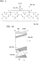
- the fuel branch portion 22a is an aggregate of a plurality of branch portions S as shown in FIG. 2 . That is, the fuel branch portion 22a, that is, the plurality of branch portions S in the fuel passage 2A, is to lengthen a pipe length (passage length) of the fuel passage 2A by sequentially branching the receiving pipe 21a (single passage), which is a single pipe. In addition, by branching the passage, an effect of creating a fine shower of liquid fuel suitable for combustion can be expected.
- a passage branching method in which a single passage is branched into a plurality of passages with a single branch portion S may be employed, but in the present embodiment as will be described later, an equivalent inertance L in a vibration equivalent circuit is increased by lengthening the pipe length (passage length) of the fuel passage 2A. Therefore, the fuel branch portion 22a employs a tournament-type branch form that increases the pipe length (passage length) of the fuel passage 2A, for example, by providing the plurality of branch portions S, and sequentially repeating branching into two passages at each branch portion S as shown in FIG. 2 , without branching the passage into the plurality of passages at one location.
- the fuel branch portion 22a distributes the liquid fuel flowing in from the receiving pipe 21a to the plurality of branch pipes 23a.
- the plurality of branch pipes 23a are pipes connected to the fuel branch portion 22a via the plurality of branch portions S. These branch pipes 23a guide the liquid fuel flowing in from the fuel branch portion 22a to the fuel injector 3A.
- branch pipes 23a constitute a cooling passage RA as shown in FIG. 1 .
- the cooling passage RA is a pipe portion that contributes to cooling the combustion chamber 4 and the nozzle skirt 5. That is, the cooling passage RA (plurality of branch pipes 23a) is mechanically provided densely on a wall surface of the combustion chamber 4 and the nozzle skirt 5 so as to be adjacent to each other as shown in FIGs. 3A and 3B to cool the combustion chamber 4 and the nozzle skirt 5 by the liquid fuel circulating therein.
- branch pipes 23a are provided over an entire wall surface of the combustion chamber 4, and on a wall surface of the nozzle skirt 5 from a base end 5a (upper end) to an end portion 5b (lower end) as shown in FIG. 3A . That is, these branch pipes 23a are provided over an entire surface of the combustion chamber 4 and the nozzle skirt 5.
- branch pipes 23a are spirally provided with respect to wall surfaces of the combustion chamber 4 and the nozzle skirt 5 and are folded back at the end portion 5b of the nozzle skirt 5, and the branch pipes 23a adjacent to each other are provided such that flow directions of the liquid fuel are opposite to each other as shown in FIG. 3B . That is, the plurality of branch pipes 23a are provided such that the liquid fuel flows in a spiral and reciprocating manner from an upper end of the combustion chamber 4 to the end portion 5b (lower end) of the nozzle skirt 5. Furthermore, the branch pipes 23a may not have a spiral shape as long as the required passage length of the fuel passage 2A can be obtained.
- a total cross-sectional area of the plurality of branch pipes 23a is equal to a cross-sectional area of the single receiving pipe 21a. That is, the fuel branch portion 22a (branch portion S) branches the fuel passage 2A without changing the passage cross-sectional area in front and behind.
- the pipe length (passage length) of the fuel passage 2A is also lengthened by the plurality of branch pipes 23a.
- the equivalent inertance L in the vibration equivalent circuit can be sufficiently increased.
- the oxidant passage 2B is a metal pipe that guides the oxidant supplied from the oxidant supply system to the oxidant injector 3B via the oxidant receiving portion 1B.
- the oxidant passage 2B includes a receiving pipe 21b, an oxidant branch portion 22b, and a plurality of branch pipes 23b.
- the receiving pipe 21b is a single pipe connecting the oxidant receiving portion 1B and the oxidant branch portion 22b to each other to circulate the oxidant from the oxidant receiving portion 1B to the oxidant branch portion 22b.
- the oxidant branch portion 22b is an aggregate of a plurality of branch portions S as shown in FIG. 2 .
- the oxidant branch portion 22b that is, the plurality of branch portions S in the oxidant passage 2B, is to lengthen a pipe length (passage length) of the oxidant passage 2B by sequentially branching the receiving pipe 21b (single passage), which is a single pipe.
- the oxidant branch portion 22b employs a branch form that increases the pipe length (passage length) of the oxidant passage 2B by providing the plurality of branch portions S, and sequentially repeating branching into two passages at each branch portion S as shown in FIG. 2 , without branching the passage into the plurality of passages at one location.
- the oxidant branch portion 22b distributes the oxidant flowing in from the receiving pipe 21b to the plurality of branch pipes 23b.
- the plurality of branch pipes 23b are pipes connected to the oxidant branch portion 22b via the plurality of branch portions S. These branch pipes 23b guide the oxidant flowing in from the oxidant branch portion 22b to the oxidant injector 3B.
- these branch pipes 23 b constitute a cooling passage RB as shown in FIG. 1 .
- the cooling passage RB is a pipe portion that contributes to cooling the combustion chamber 4 and the nozzle skirt 5. That is, the cooling passage RB (plurality of branch pipes 23b) is mechanically provided densely on a wall surface of the combustion chamber 4 and the nozzle skirt 5 so as to be adjacent to each other to cool the combustion chamber 4 and the nozzle skirt 5 by the oxidant circulating therein.
- branch pipes 23b are provided over an entire wall surface of the combustion chamber 4, and on a wall surface of the nozzle skirt 5 from a base end 5a (upper end) to an end portion 5b (lower end). That is, these branch pipes 23b are provided over an entire surface of the combustion chamber 4 and the nozzle skirt 5.
- branch pipes 23b are spirally provided with respect to wall surfaces of the combustion chamber 4 and the nozzle skirt 5 and are folded back at the end portion 5b of the nozzle skirt 5, and the branch pipes 23b adjacent to each other are provided such that flow directions of the oxidant are opposite to each other as shown in FIG. 3B . That is, the plurality of branch pipes 23b are provided such that the oxidant flows in a spiral and reciprocating manner from an upper end of the combustion chamber 4 to the end portion 5b (lower end) of the nozzle skirt 5.
- a total cross-sectional area of the plurality of branch pipes 23b is equal to a cross-sectional area of the single receiving pipe 21b. That is, the oxidant branch portion 22b (branch portion S) branches the oxidant passage 2B without changing the passage cross-sectional area in front and behind.
- the pipe length (passage length) of the oxidant passage 2B is also lengthened by the plurality of branch pipes 23b.
- the equivalent inertance L in the vibration equivalent circuit can be sufficiently increased.
- the fuel injector 3A is a fuel injection nozzle provided near an end (upper end) of the combustion chamber 4 to inject liquid fuel flowing in from the fuel passage 2A into the combustion chamber 4. That is, the fuel injector 3A injects fuel into a combustion room, which is an internal space of the combustion chamber 4.
- the fuel injector 3A is provided for each of the plurality of branch pipes 23a, for example.
- the oxidant injector 3B is an oxidant injection nozzle provided near an end (upper end) of the combustion chamber 4 to inject an oxidant flowing in from the oxidant passage 2B into the combustion chamber 4. That is, the oxidant injector 3B injects the oxidant into the combustion room, which is an internal space of the combustion chamber 4.
- the oxidant injector 3B is provided for each of the plurality of branch pipes 23b, for example.
- the combustion chamber 4 is a hollow body including the above-mentioned combustion room as an internal space.
- the combustion chamber 4 burns the fuel injected from the fuel injector 3A using the oxidant injected from the oxidant injector 3B in the combustion room.
- the cooling passage RA, RB constitutes a cooling mechanism for sufficiently cooling the combustion chamber 4.
- the nozzle skirt 5 is a funnel-shaped injection nozzle that communicates with the combustion room to inject the combustion gas to an outside.
- the reusable rocket in the present embodiment flies using a reaction force obtained when the combustion gas is injected from the nozzle skirt 5 to the outside as a thrust.
- the nozzle skirt 5 needs to have a wall surface cooling function since an inner wall surface thereof is exposed to the combustion gas.
- the cooling passage RA, RB constitutes a cooling mechanism for sufficiently cooling the nozzle skirt 5.
- FIG. 4 is a vibration equivalent circuit (vibration model) of the combustor C for the rocket engine.
- vibration is generated by coupling a pressure fluctuation in the fuel passage 2A (liquid fuel passage) from the fuel receiving portion 1A to the fuel injector 3A, and in the oxidant passage 2B from the oxidant receiving portion 1B to the oxidant injector 3B with a fluctuation of pressure (combustion pressure) in the combustion chamber 4. That is, the combustor C for the rocket engine vibrates due to the circulation of the liquid fuel and the oxidant as one of vibration sources.
- the vibration equivalent circuit shown in FIG. 4 shows how each component (mechanical element) of the combustor C for the rocket engine shown in FIG. 1 acts on vibration caused by the vibration sources. That is, the vibration equivalent circuit of the combustor C for the rocket engine is expressed as a series connection circuit of an equivalent inertance L and an equivalent resistance R, and the vibration is suppressed by adjusting a magnitude of the equivalent inertance L or/and the equivalent resistance R.
- the equivalent inertance L is expressed by the following equation, which is an amount that depends on the passage lengths of the fuel passage 2A and the oxidant passage 2B.
- Each parameter in the equation is as shown in Table 1.
- a front equation is an equation showing the equivalent inertance L in a dimensional manner
- a rear equation is an equation showing the equivalent inertance L in a dimensionless manner.
- the equivalent resistance R is an amount that depends on a pressure loss of the liquid fuel and the oxidant in the fuel passage 2A, the oxidant passage 2B, the fuel injector 3A, and the oxidant injector 3B.
- the equivalent resistance R is an amount that makes it difficult for the combustor C for the rocket engine to vibrate by increasing the resistance and makes it easy for the combustor C for the rocket engine to vibrate by decreasing the resistance.
- the equivalent inertance L is an amount that tends to increase when a combustion pressure mean value is lowered, and therefore has a property of suppressing vibration in a low thrust. That is, in a case where the equivalent inertance L is optimally set for vibration in the normal thrust, when a thrust of the combustor C for the rocket engine is reduced, the equivalent inertance L increases, so that the combustor C for the rocket engine is in a state where it is difficult to vibrate.
- the pressure loss is a pressure difference (injection differential pressure) between a pressure of the fuel in the fuel injector 3A and a combustion pressure in the combustion chamber 4, and a pressure difference (injection differential pressure) between a pressure of the oxidant in the oxidant injector 3B and a combustion pressure in the combustion chamber 4 and is proportional to the square of mass flow rates of the fuel and the oxidant.
- the combustion pressure in the combustion room is proportional to the mass flow rates. Therefore, when the thrust of the combustor C for the rocket engine is reduced, the equivalent resistance R is reduced, such that the combustor C for the rocket engine is likely to vibrate.
- a thrust range of the disposable rocket engine is narrow, so vibration is suppressed by optimally setting the equivalent resistance in the normal thrust.
- the combustor C for the rocket engine according to the present embodiment is mounted and used in a reusable rocket engine, the passage lengths of the fuel passage 2A and the oxidant passage 2B are lengthened to increase the equivalent inertance L, thereby securing a vibration margin in a case where used with a thrust that is relatively significantly reduced from the normal thrust.
- the equivalent inertance L in the vibration equivalent circuit of the combustor C for the rocket engine is increased by lengthening the passage lengths of the fuel passage 2A and the oxidant passage 2B, thereby effectively suppressing the vibration of the combustor C for the rocket engine when operating with a plurality of thrusts (operating points) in a relatively wide thrust range.
- a total cross-sectional area of the plurality of branch pipes 23a, 23b is equal to a cross-sectional area of the single receiving pipes 21a, 21b, the passages of the liquid fuel and the oxidant (the fuel passage 2A and the oxidant passage 2B) can be branched without changing the equivalent resistance R. Therefore, according to the present embodiment, it is possible to consider vibration suppression by focusing only on the equivalent inertance L without considering a change in the equivalent resistance R.
- the passage lengths of the fuel passage 2A and the oxidant passage 2B are lengthened by providing the fuel branch portion 22a in the fuel passage 2A and providing the oxidant branch portion 22b in the oxidant passage 2B, that is, by providing the plurality of branch portions S in the fuel passage 2A and the oxidant passage 2B, thereby increasing the equivalent inertance L. Therefore, according to the present embodiment, it is possible to easily increase the equivalent inertance L.
- the fuel branch portion 22a is provided in front of the cooling passage RA, and the oxidant branch portion 22b is provided in front of the cooling passage RB, that is, since the plurality of branch portions S are provided in front of the cooling passages RA, RB, it is possible to easily lengthen the passage lengths of the fuel passage 2A and the oxidant passage 2B.
- the cooling passages RA, RB that is, the branch pipes 23a, 23b, are folded back at the end portion 5b of the nozzle skirt 5 and are spirally provided with respect to the combustion chamber 4 and the nozzle skirt 5, it is possible to easily lengthen the passage lengths of the fuel passage 2A and the oxidant passage 2B even with such an arrangement of the branch pipes 23a, 23b.
- a combustor for a rocket engine capable of effectively suppressing vibration when operating with a plurality of thrusts.
Landscapes
- Engineering & Computer Science (AREA)
- Chemical & Material Sciences (AREA)
- Combustion & Propulsion (AREA)
- Mechanical Engineering (AREA)
- General Engineering & Computer Science (AREA)
- Testing Of Engines (AREA)
Abstract
Description
- The present disclosure relates to a combustor for a rocket engine.
- Priority is claimed on
Japanese Patent Application No. 2020-033320, filed on February 28, 2020 - The following
Patent Document 1 discloses a thrust control apparatus and a thrust control method for a liquid rocket engine. The purpose of the thrust control apparatus and thrust control method is to reduce the possibility of generating low-frequency combustion vibration (chugging) caused by an extreme decrease in injection differential pressure (a difference between an injection pressure and a combustion pressure) when operating in a reduced thrust range by controlling a thrust to be reduced in the thrust control of a rocket engine. According to the thrust control apparatus and thrust control method, in a liquid rocket engine that injects a liquid propellant into a combustion room through an injection orifice, a temperature control means for controlling the temperature of the liquid propellant at an upstream side of the injection orifice is provided and the temperature of the liquid propellant is raised so as to secure an injection differential pressure needed for reduction control using a saturated vapor pressure of the liquid propellant when controlling the thrust of the engine to be reduced. - [Patent Document 1]
Japanese Unexamined Patent Application, First Publication No. 2013-155655 - From the viewpoint of suppressing vibration of a combustor for a rocket engine, in a liquid rocket engine described in
Patent Document 1, vibration can be suppressed in a single thrust (operating point) by changing a shape of an injection orifice, but vibration cannot be suppressed in a plurality of thrusts. For example, unlike a disposable type, a combustor for a reusable rocket engine is used in a relatively wide thrust range for a landing operation and the like. Therefore, in the liquid rocket engine described inPatent Document 1, the vibration of the combustor for the reusable rocket engine cannot be effectively suppressed over an entire thrust range. - The present disclosure has been made in view of the above circumstances, and an object of the present disclosure is to provide a combustor for a rocket engine capable of effectively suppressing vibration when operating with a plurality of thrusts.
- A combustor for a rocket engine according to a first aspect of the present disclosure includes a combustion room configured to cause a combustion reaction between a fuel and an oxidant, an injector configured to inject the fuel and the oxidant into the combustion room, a nozzle skirt configured to inject combustion gas generated by the combustion reaction to an outside, and an inertance increasing portion configured to increase an equivalent inertance in a vibration equivalent circuit of the combustor for the rocket engine.
- The combustor for the rocket engine according to a second aspect of the present disclosure may further include, in the first aspect described above, a fuel passage configured to guide the fuel to the combustion room, and an oxidant passage configured to guide the oxidant to the combustion room, in which the inertance increasing portion increases the equivalent inertance by providing a plurality of branch portions in the fuel passage or/and the oxidant passage to lengthen a passage length thereof.
- In the combustor for the rocket engine according to a third aspect of the present disclosure, in the second aspect described above, the inertance increasing portion may branch the fuel passage or/and the oxidant passage without changing a passage cross-sectional area in front of and behind the branch portion.
- In the combustor for the rocket engine according to a fourth aspect of the present disclosure, in the second or third aspect described above, the fuel passage or/and the oxidant passage may include a cooling passage configured to cool the nozzle skirt, and in the inertance increasing portion, the plurality of branch portions are provided in front of the cooling passage.
- In the combustor for the rocket engine according to a fifth aspect of the present disclosure, in the fourth aspect described above, the cooling passage may be provided from a base end to an end portion of the nozzle skirt and folded back at the end portion.
- In the combustor for the rocket engine according to a sixth aspect of the present disclosure, in the fourth or fifth aspect described above, the cooling passage may be spirally provided with respect to the nozzle skirt.
- According to the present disclosure, it is possible to provide a combustor for a rocket engine capable of effectively suppressing vibration when operating with a plurality of thrusts.
-
-
FIG. 1 is a schematic diagram showing a configuration of a combustor for a rocket engine according to an embodiment of the present disclosure. -
FIG. 2 is a schematic diagram showing details of a fuel branch portion and an oxidant branch portion in an embodiment of the present disclosure. -
FIG. 3A is a view showing an arrangement of branch pipes in an embodiment of the present disclosure. -
FIG. 3B is a partially enlarged view of branch pipes in an embodiment of the present disclosure. -
FIG. 4 is a vibration equivalent circuit of a combustor for a rocket engine according to an embodiment of the present disclosure. - Hereinafter, an embodiment of the present disclosure will be described with reference to the drawings.
- A combustor C for a rocket engine according to the present embodiment is a combustor constituting a reusable rocket engine. That is, unlike a combustor for a disposable rocket in the related art, the combustor C for the rocket engine is a combustor that operates with a plurality of thrusts (operating points) in a wide range, that is, operates even with a thrust (low operating point) that is significantly lower than a normal thrust, in addition to the normal thrust (normal operating point).
- As shown in
FIG. 1 , the combustor C for the rocket engine includes afuel receiving portion 1A, anoxidant receiving portion 1B, afuel passage 2A, anoxidant passage 2B, afuel injector 3A, anoxidant injector 3B, acombustion chamber 4, and anozzle skirt 5. Furthermore, thefuel passage 2A and theoxidant passage 2B in the present embodiment correspond to an inertance increasing portion of the present disclosure. - The
fuel receiving portion 1A is a receiving port that receives a fuel from a fuel supply system. That is, thefuel receiving portion 1A is a receiving port that receives a liquid fuel at a predetermined pressure from the fuel supply system configured with a fuel tank, a fuel pump, and the like, and supplies the liquid fuel to thefuel passage 2A. The liquid fuel is, for example, liquid hydrogen or liquefied natural gas. - The
oxidant receiving portion 1B is a receiving port for receiving an oxidant from an oxidant supply system. That is, theoxidant receiving portion 1B is a receiving port that receives an oxidant at a predetermined pressure from the oxidant supply system configured with an oxidant tank, an oxidant pump, and the like, and supplies the oxidant to theoxidant passage 2B. The oxidant is, for example, liquid oxygen. - The
fuel passage 2A is a metal pipe that guides the liquid fuel supplied from the fuel supply system to thefuel injector 3A via thefuel receiving portion 1A. Thefuel passage 2A includes a receivingpipe 21a, afuel branch portion 22a, and a plurality ofbranch pipes 23a. The receivingpipe 21a is a single pipe connecting thefuel receiving portion 1A and thefuel branch portion 22a to each other to circulate the liquid fuel from thefuel receiving portion 1A to thefuel branch portion 22a. - The
fuel branch portion 22a is an aggregate of a plurality of branch portions S as shown inFIG. 2 . That is, thefuel branch portion 22a, that is, the plurality of branch portions S in thefuel passage 2A, is to lengthen a pipe length (passage length) of thefuel passage 2A by sequentially branching thereceiving pipe 21a (single passage), which is a single pipe. In addition, by branching the passage, an effect of creating a fine shower of liquid fuel suitable for combustion can be expected. - Here, a passage branching method in which a single passage is branched into a plurality of passages with a single branch portion S may be employed, but in the present embodiment as will be described later, an equivalent inertance L in a vibration equivalent circuit is increased by lengthening the pipe length (passage length) of the
fuel passage 2A. Therefore, thefuel branch portion 22a employs a tournament-type branch form that increases the pipe length (passage length) of thefuel passage 2A, for example, by providing the plurality of branch portions S, and sequentially repeating branching into two passages at each branch portion S as shown inFIG. 2 , without branching the passage into the plurality of passages at one location. - The
fuel branch portion 22a distributes the liquid fuel flowing in from thereceiving pipe 21a to the plurality ofbranch pipes 23a. The plurality ofbranch pipes 23a are pipes connected to thefuel branch portion 22a via the plurality of branch portions S. Thesebranch pipes 23a guide the liquid fuel flowing in from thefuel branch portion 22a to thefuel injector 3A. - In addition, these
branch pipes 23a constitute a cooling passage RA as shown inFIG. 1 . The cooling passage RA is a pipe portion that contributes to cooling thecombustion chamber 4 and thenozzle skirt 5. That is, the cooling passage RA (plurality ofbranch pipes 23a) is mechanically provided densely on a wall surface of thecombustion chamber 4 and thenozzle skirt 5 so as to be adjacent to each other as shown inFIGs. 3A and3B to cool thecombustion chamber 4 and thenozzle skirt 5 by the liquid fuel circulating therein. - These
branch pipes 23a are provided over an entire wall surface of thecombustion chamber 4, and on a wall surface of thenozzle skirt 5 from abase end 5a (upper end) to anend portion 5b (lower end) as shown inFIG. 3A . That is, thesebranch pipes 23a are provided over an entire surface of thecombustion chamber 4 and thenozzle skirt 5. - In addition, these
branch pipes 23a are spirally provided with respect to wall surfaces of thecombustion chamber 4 and thenozzle skirt 5 and are folded back at theend portion 5b of thenozzle skirt 5, and thebranch pipes 23a adjacent to each other are provided such that flow directions of the liquid fuel are opposite to each other as shown inFIG. 3B . That is, the plurality ofbranch pipes 23a are provided such that the liquid fuel flows in a spiral and reciprocating manner from an upper end of thecombustion chamber 4 to theend portion 5b (lower end) of thenozzle skirt 5. Furthermore, thebranch pipes 23a may not have a spiral shape as long as the required passage length of thefuel passage 2A can be obtained. - Here, a total cross-sectional area of the plurality of
branch pipes 23a is equal to a cross-sectional area of thesingle receiving pipe 21a. That is, thefuel branch portion 22a (branch portion S) branches thefuel passage 2A without changing the passage cross-sectional area in front and behind. - In the
fuel passage 2A configured in this manner, in addition to lengthening the pipe length (passage length) of thefuel passage 2A by thefuel branch portion 22a, the pipe length (passage length) of thefuel passage 2A is also lengthened by the plurality ofbranch pipes 23a. In the foregoingfuel passage 2A, since the passage length of the fuel passage through which the liquid fuel circulates is longer than that of a combustor for a rocket engine in the related art, the equivalent inertance L in the vibration equivalent circuit can be sufficiently increased. - The
oxidant passage 2B is a metal pipe that guides the oxidant supplied from the oxidant supply system to theoxidant injector 3B via theoxidant receiving portion 1B. Theoxidant passage 2B includes a receivingpipe 21b, anoxidant branch portion 22b, and a plurality ofbranch pipes 23b. The receivingpipe 21b is a single pipe connecting theoxidant receiving portion 1B and theoxidant branch portion 22b to each other to circulate the oxidant from theoxidant receiving portion 1B to theoxidant branch portion 22b. - The
oxidant branch portion 22b is an aggregate of a plurality of branch portions S as shown inFIG. 2 . Theoxidant branch portion 22b, that is, the plurality of branch portions S in theoxidant passage 2B, is to lengthen a pipe length (passage length) of theoxidant passage 2B by sequentially branching the receivingpipe 21b (single passage), which is a single pipe. - As described above, in the present embodiment, an equivalent inertance is increased by lengthening the pipe length (passage length) of the
oxidant passage 2B. Therefore, theoxidant branch portion 22b employs a branch form that increases the pipe length (passage length) of theoxidant passage 2B by providing the plurality of branch portions S, and sequentially repeating branching into two passages at each branch portion S as shown inFIG. 2 , without branching the passage into the plurality of passages at one location. - The
oxidant branch portion 22b distributes the oxidant flowing in from the receivingpipe 21b to the plurality ofbranch pipes 23b. The plurality ofbranch pipes 23b are pipes connected to theoxidant branch portion 22b via the plurality of branch portions S. Thesebranch pipes 23b guide the oxidant flowing in from theoxidant branch portion 22b to theoxidant injector 3B. - In addition, these
branch pipes 23 b constitute a cooling passage RB as shown inFIG. 1 . Similar to the cooling passage RA, the cooling passage RB is a pipe portion that contributes to cooling thecombustion chamber 4 and thenozzle skirt 5. That is, the cooling passage RB (plurality ofbranch pipes 23b) is mechanically provided densely on a wall surface of thecombustion chamber 4 and thenozzle skirt 5 so as to be adjacent to each other to cool thecombustion chamber 4 and thenozzle skirt 5 by the oxidant circulating therein. - Similar to the
branch pipes 23a of thefuel passage 2A, thesebranch pipes 23b are provided over an entire wall surface of thecombustion chamber 4, and on a wall surface of thenozzle skirt 5 from abase end 5a (upper end) to anend portion 5b (lower end). That is, thesebranch pipes 23b are provided over an entire surface of thecombustion chamber 4 and thenozzle skirt 5. - In addition, similar to the
branch pipes 23a of thefuel passage 2A, thesebranch pipes 23b are spirally provided with respect to wall surfaces of thecombustion chamber 4 and thenozzle skirt 5 and are folded back at theend portion 5b of thenozzle skirt 5, and thebranch pipes 23b adjacent to each other are provided such that flow directions of the oxidant are opposite to each other as shown inFIG. 3B . That is, the plurality ofbranch pipes 23b are provided such that the oxidant flows in a spiral and reciprocating manner from an upper end of thecombustion chamber 4 to theend portion 5b (lower end) of thenozzle skirt 5. - Here, a total cross-sectional area of the plurality of
branch pipes 23b is equal to a cross-sectional area of thesingle receiving pipe 21b. That is, theoxidant branch portion 22b (branch portion S) branches theoxidant passage 2B without changing the passage cross-sectional area in front and behind. - In the
oxidant passage 2B configured in this manner, in addition to lengthening the pipe length (passage length) of theoxidant passage 2B by theoxidant branch portion 22b, the pipe length (passage length) of theoxidant passage 2B is also lengthened by the plurality ofbranch pipes 23b. In the foregoingoxidant passage 2B, since the passage length of the oxidant passage through which the oxidant circulates is longer than that of a combustor for a rocket engine in the related art, the equivalent inertance L in the vibration equivalent circuit can be sufficiently increased. - The
fuel injector 3A is a fuel injection nozzle provided near an end (upper end) of thecombustion chamber 4 to inject liquid fuel flowing in from thefuel passage 2A into thecombustion chamber 4. That is, thefuel injector 3A injects fuel into a combustion room, which is an internal space of thecombustion chamber 4. Thefuel injector 3A is provided for each of the plurality ofbranch pipes 23a, for example. - The
oxidant injector 3B is an oxidant injection nozzle provided near an end (upper end) of thecombustion chamber 4 to inject an oxidant flowing in from theoxidant passage 2B into thecombustion chamber 4. That is, theoxidant injector 3B injects the oxidant into the combustion room, which is an internal space of thecombustion chamber 4. Theoxidant injector 3B is provided for each of the plurality ofbranch pipes 23b, for example. - The
combustion chamber 4 is a hollow body including the above-mentioned combustion room as an internal space. Thecombustion chamber 4 burns the fuel injected from thefuel injector 3A using the oxidant injected from theoxidant injector 3B in the combustion room. - In the combustion room, high-temperature and high-pressure combustion gas is generated by a combustion reaction between the fuel and the oxidant. That is, the
combustion chamber 4 needs to have a wall surface cooling function in order to ensure sufficient durability since an inner wall surface thereof is exposed to the combustion gas. The cooling passage RA, RB constitutes a cooling mechanism for sufficiently cooling thecombustion chamber 4. - The
nozzle skirt 5 is a funnel-shaped injection nozzle that communicates with the combustion room to inject the combustion gas to an outside. The reusable rocket in the present embodiment flies using a reaction force obtained when the combustion gas is injected from thenozzle skirt 5 to the outside as a thrust. Similar to thecombustion chamber 4, thenozzle skirt 5 needs to have a wall surface cooling function since an inner wall surface thereof is exposed to the combustion gas. The cooling passage RA, RB constitutes a cooling mechanism for sufficiently cooling thenozzle skirt 5. - Next, a vibration suppression function of the combustor C for the rocket engine according to the present embodiment will be described in detail with reference to
FIG. 4 . - First,
FIG. 4 is a vibration equivalent circuit (vibration model) of the combustor C for the rocket engine. In the combustor C for the rocket engine, vibration is generated by coupling a pressure fluctuation in thefuel passage 2A (liquid fuel passage) from thefuel receiving portion 1A to thefuel injector 3A, and in theoxidant passage 2B from theoxidant receiving portion 1B to theoxidant injector 3B with a fluctuation of pressure (combustion pressure) in thecombustion chamber 4. That is, the combustor C for the rocket engine vibrates due to the circulation of the liquid fuel and the oxidant as one of vibration sources. - The vibration equivalent circuit shown in
FIG. 4 shows how each component (mechanical element) of the combustor C for the rocket engine shown inFIG. 1 acts on vibration caused by the vibration sources. That is, the vibration equivalent circuit of the combustor C for the rocket engine is expressed as a series connection circuit of an equivalent inertance L and an equivalent resistance R, and the vibration is suppressed by adjusting a magnitude of the equivalent inertance L or/and the equivalent resistance R. - Here, the equivalent inertance L is expressed by the following equation, which is an amount that depends on the passage lengths of the
fuel passage 2A and theoxidant passage 2B. Each parameter in the equation is as shown in Table 1. Furthermore, in the equation, a front equation is an equation showing the equivalent inertance L in a dimensional manner, and a rear equation is an equation showing the equivalent inertance L in a dimensionless manner.


-
[Table 1] l PASSAGE LENGTH [m] A PASSAGE CROSS-SECTIONAL AREA [m2] ρ FLUID DENSITY (Mean) [kg/m3] 
MASS FLOW RATE Mean Value [kg/s] Pc COMBUSTION PRESSURE Mean Value [Pa] τstay PROPELLANT STAY TIME IN THE COMBUSTOR [s] - Furthermore, the equivalent resistance R is an amount that depends on a pressure loss of the liquid fuel and the oxidant in the
fuel passage 2A, theoxidant passage 2B, thefuel injector 3A, and theoxidant injector 3B. The equivalent resistance R is an amount that makes it difficult for the combustor C for the rocket engine to vibrate by increasing the resistance and makes it easy for the combustor C for the rocket engine to vibrate by decreasing the resistance. - As shown in the equation, the equivalent inertance L is an amount that tends to increase when a combustion pressure mean value is lowered, and therefore has a property of suppressing vibration in a low thrust. That is, in a case where the equivalent inertance L is optimally set for vibration in the normal thrust, when a thrust of the combustor C for the rocket engine is reduced, the equivalent inertance L increases, so that the combustor C for the rocket engine is in a state where it is difficult to vibrate.
- In a normal rocket engine, the pressure loss is a pressure difference (injection differential pressure) between a pressure of the fuel in the
fuel injector 3A and a combustion pressure in thecombustion chamber 4, and a pressure difference (injection differential pressure) between a pressure of the oxidant in theoxidant injector 3B and a combustion pressure in thecombustion chamber 4 and is proportional to the square of mass flow rates of the fuel and the oxidant. In addition, the combustion pressure in the combustion room is proportional to the mass flow rates. Therefore, when the thrust of the combustor C for the rocket engine is reduced, the equivalent resistance R is reduced, such that the combustor C for the rocket engine is likely to vibrate. - In the design concept of a disposable rocket engine in the related art, a thrust range of the disposable rocket engine is narrow, so vibration is suppressed by optimally setting the equivalent resistance in the normal thrust. On the contrary, since the combustor C for the rocket engine according to the present embodiment is mounted and used in a reusable rocket engine, the passage lengths of the
fuel passage 2A and theoxidant passage 2B are lengthened to increase the equivalent inertance L, thereby securing a vibration margin in a case where used with a thrust that is relatively significantly reduced from the normal thrust. - According to the present embodiment, the equivalent inertance L in the vibration equivalent circuit of the combustor C for the rocket engine is increased by lengthening the passage lengths of the
fuel passage 2A and theoxidant passage 2B, thereby effectively suppressing the vibration of the combustor C for the rocket engine when operating with a plurality of thrusts (operating points) in a relatively wide thrust range. - In addition, according to the present embodiment, since a total cross-sectional area of the plurality of
branch pipes single receiving pipes fuel passage 2A and theoxidant passage 2B) can be branched without changing the equivalent resistance R. Therefore, according to the present embodiment, it is possible to consider vibration suppression by focusing only on the equivalent inertance L without considering a change in the equivalent resistance R. - In addition, according to the present embodiment, the passage lengths of the
fuel passage 2A and theoxidant passage 2B are lengthened by providing thefuel branch portion 22a in thefuel passage 2A and providing theoxidant branch portion 22b in theoxidant passage 2B, that is, by providing the plurality of branch portions S in thefuel passage 2A and theoxidant passage 2B, thereby increasing the equivalent inertance L. Therefore, according to the present embodiment, it is possible to easily increase the equivalent inertance L. - In addition, according to the present embodiment, since the
fuel branch portion 22a is provided in front of the cooling passage RA, and theoxidant branch portion 22b is provided in front of the cooling passage RB, that is, since the plurality of branch portions S are provided in front of the cooling passages RA, RB, it is possible to easily lengthen the passage lengths of thefuel passage 2A and theoxidant passage 2B. - In addition, according to the present embodiment, since the cooling passages RA, RB, that is, the
branch pipes end portion 5b of thenozzle skirt 5 and are spirally provided with respect to thecombustion chamber 4 and thenozzle skirt 5, it is possible to easily lengthen the passage lengths of thefuel passage 2A and theoxidant passage 2B even with such an arrangement of thebranch pipes - Furthermore, the present disclosure is not limited to the above embodiment, and for example, the following modifications are considered.
- (1) In the above embodiment, the
fuel branch portion 22a is provided in thefuel passage 2A, and theoxidant branch portion 22b is provided in theoxidant passage 2B, but the present disclosure is not limited thereto. That is, either one of thefuel branch portion 22a or theoxidant branch portion 22b may be provided. - (2) In the above embodiment, a total cross-sectional area of the plurality of
branch pipes single receiving pipes fuel passage 2A and theoxidant passage 2B may be branched so as to change passage cross-sectional areas in front of and behind thefuel branch portion 22a and theoxidant branch portion 22b. - (3) In the above embodiment, the
branch pipes end portion 5b of thenozzle skirt 5, but the present disclosure is not limited thereto. Thebranch pipes combustion chamber 4 and theend portion 5b of thenozzle skirt 5. - (4) In the above embodiment, as shown in
FIG. 2 , one branch portion S is bifurcated, but the present disclosure is not limited thereto. The number of branches in one branch portion S may be three or more. - According to the present disclosure, it is possible to provide a combustor for a rocket engine capable of effectively suppressing vibration when operating with a plurality of thrusts.
-
- C: Combustor for a rocket engine
- RA: Cooling passage
- RB: Cooling passage
- S: Branch portion
- 1A: Fuel receiving portion
- 1B: Oxidant receiving portion
- 2A: Fuel passage (inertance increasing portion)
- 21a: Receiving pipe
- 22a: Fuel branch portion
- 23a: Branch pipe
- 2B: Oxidant passage (inertance increasing portion)
- 21b: Receiving pipe
- 22b: Oxidant branch portion
- 23b: Branch pipe
- 3A: Fuel injector
- 3B: Oxidant injector
- 4: Combustion chamber
- 5: Nozzle skirt
- 5a: Base end
- 5b: End portion
Claims (6)
- A combustor for a rocket engine comprising:a combustion room configured to cause a combustion reaction between a fuel and an oxidant;an injector configured to inject the fuel and the oxidant into the combustion room; a nozzle skirt configured to inject combustion gas generated by the combustion reaction to an outside; andan inertance increasing portion configured to increase an equivalent inertance in a vibration equivalent circuit of the combustor for the rocket engine.
- The combustor for the rocket engine according to Claim 1, further comprising:a fuel passage configured to guide the fuel to the combustion room; andan oxidant passage configured to guide the oxidant to the combustion room,wherein the inertance increasing portion increases the equivalent inertance by providing a plurality of branch portions in the fuel passage or/and the oxidant passage to lengthen a passage length thereof.
- The combustor for the rocket engine according to Claim 2, wherein the inertance increasing portion branches the fuel passage or/and the oxidant passage without changing a passage cross-sectional area in front of and behind the branch portion.
- The combustor for the rocket engine according to Claim 2 or 3, wherein the fuel passage or/and the oxidant passage includes a cooling passage configured to cool the nozzle skirt, and
wherein in the inertance increasing portion, the plurality of branch portions are provided in front of the cooling passage. - The combustor for the rocket engine according to Claim 4, wherein the cooling passage is provided from a base end to an end portion of the nozzle skirt and is folded back at the end portion.
- The combustor for the rocket engine according to Claim 4 or 5, wherein the cooling passage is spirally provided with respect to the nozzle skirt.
Applications Claiming Priority (2)
| Application Number | Priority Date | Filing Date | Title |
|---|---|---|---|
| JP2020033320 | 2020-02-28 | ||
| PCT/JP2021/004584 WO2021171988A1 (en) | 2020-02-28 | 2021-02-08 | Combustion apparatus for rocket engine |
Publications (2)
| Publication Number | Publication Date |
|---|---|
| EP4112912A1 true EP4112912A1 (en) | 2023-01-04 |
| EP4112912A4 EP4112912A4 (en) | 2024-03-20 |
Family
ID=77490466
Family Applications (1)
| Application Number | Title | Priority Date | Filing Date |
|---|---|---|---|
| EP21760050.1A Pending EP4112912A4 (en) | 2020-02-28 | 2021-02-08 | COMBUSTION DEVICE FOR ROCKET ENGINE |
Country Status (4)
| Country | Link |
|---|---|
| US (1) | US12129815B2 (en) |
| EP (1) | EP4112912A4 (en) |
| JP (1) | JP7276593B2 (en) |
| WO (1) | WO2021171988A1 (en) |
Family Cites Families (13)
| Publication number | Priority date | Publication date | Assignee | Title |
|---|---|---|---|---|
| US3615054A (en) * | 1965-09-24 | 1971-10-26 | Aerojet General Co | Injectors |
| JPH01249957A (en) * | 1988-03-31 | 1989-10-05 | Toshiba Corp | Thrustor |
| JPH0968105A (en) * | 1995-08-30 | 1997-03-11 | Ishikawajima Harima Heavy Ind Co Ltd | Two-component liquid rocket engine |
| JP2001096738A (en) * | 1999-09-29 | 2001-04-10 | Seiko Epson Corp | Inkjet head |
| US6908298B1 (en) | 2001-10-30 | 2005-06-21 | Owen W. Dykema | Air-fuel injection system for stable combustion |
| US7343732B2 (en) | 2003-03-04 | 2008-03-18 | Aerojet-General Corporation | Rocket engine chamber with layered internal wall channels |
| FR2915528B1 (en) | 2007-04-25 | 2012-07-06 | Astrium Sas | METHOD AND DEVICE FOR FEEDING A SPACE PROPULSION ENGINE IN LIQUID CRYOGENIC ERGOLS. |
| US8776494B2 (en) * | 2010-06-22 | 2014-07-15 | Cal Poly Corporation | System, method and apparatus for cooling rocket motor components using a saturated liquid vapor coolant mixture |
| JP5909809B2 (en) | 2012-01-30 | 2016-04-27 | 国立研究開発法人宇宙航空研究開発機構 | Thrust control device and thrust control method for liquid rocket engine |
| EP3509842A4 (en) * | 2016-09-08 | 2020-08-12 | Additive Rocket Corporation | Fractal fluid passages apparatus |
| US20190093602A1 (en) * | 2017-09-25 | 2019-03-28 | Shapefidelity, Inc. | Rocket engine combustion chamber liner |
| PL3597897T3 (en) * | 2018-07-17 | 2024-06-24 | Arianegroup Gmbh | Combustion chamber structure, particularly for a rocket engine |
| JP7061538B2 (en) | 2018-08-31 | 2022-04-28 | 東レ・ファインケミカル株式会社 | Method for purifying diglycidylamine-based epoxy compounds |
-
2021
- 2021-02-08 EP EP21760050.1A patent/EP4112912A4/en active Pending
- 2021-02-08 WO PCT/JP2021/004584 patent/WO2021171988A1/en not_active Ceased
- 2021-02-08 JP JP2022503232A patent/JP7276593B2/en active Active
-
2022
- 2022-08-01 US US17/816,556 patent/US12129815B2/en active Active
Also Published As
| Publication number | Publication date |
|---|---|
| WO2021171988A1 (en) | 2021-09-02 |
| US12129815B2 (en) | 2024-10-29 |
| JP7276593B2 (en) | 2023-05-18 |
| JPWO2021171988A1 (en) | 2021-09-02 |
| EP4112912A4 (en) | 2024-03-20 |
| US20220364529A1 (en) | 2022-11-17 |
Similar Documents
| Publication | Publication Date | Title |
|---|---|---|
| Teasley et al. | A review towards the design optimization of high performance additively manufactured rotating detonation rocket engine injectors | |
| RU2757376C2 (en) | Jet propulsion unit and method for operating jet propulsion unit | |
| EP1741917A2 (en) | Booster rocket engine using gaseous hydrocarbon in catalytically enhanced gas generator cycle | |
| US20190003423A1 (en) | Dual-expander short-length aerospike engine | |
| US5857323A (en) | Rocket engine burner with porous metal injector for throttling over a large thrust range | |
| US20180051883A1 (en) | Pre-mixing based fuel nozzle for use in a combustion turbine engine | |
| CN109154439A (en) | For the injector assembly in the combustion system of gas-turbine unit and the pipe arrangement structure including such injector assembly | |
| JP5044013B2 (en) | Method and apparatus for supplying cryogenic liquid propellant to space propulsion engine | |
| JP6258101B2 (en) | Jet engine, flying object and operation method of jet engine | |
| EP2580448B1 (en) | Gas turbine and method for operating said gas turbine | |
| US20220364529A1 (en) | Combustor for rocket engine | |
| JP5909809B2 (en) | Thrust control device and thrust control method for liquid rocket engine | |
| EP4411243A1 (en) | Injector with fairing and annular passage for hydrogen-driven gas turbine engine | |
| EP4411241A1 (en) | Fuel system with pilot and main injectors for hydrogen-driven gas turbine engine | |
| EP4491858A1 (en) | Gas turbine engine fuel system | |
| KR101005756B1 (en) | Gas generator mixing ratio control device and its control method in turbo pump gas generator connection test | |
| US20070051089A1 (en) | Augmentor flow control with thermal recirculation function and method of thermal recirculation control using augmentor valves | |
| Keller et al. | Monolithic Tri-Coaxial Methane-Oxygen Rocket Injector Enabled by Additive-Manufacturing | |
| US3453827A (en) | Injection throttling | |
| JP6906601B2 (en) | Rocket engine injector element | |
| KR101179666B1 (en) | An assembly having cooling channel | |
| CONNAUGHTON | Application of a hydrazine gas generator to vacuum ejector pumping of a chemical laser | |
| Greuel et al. | Test facilities for SCORE-D | |
| JP2006156790A (en) | Gas laser generator | |
| JP2009209862A (en) | Combustor |
Legal Events
| Date | Code | Title | Description |
|---|---|---|---|
| STAA | Information on the status of an ep patent application or granted ep patent |
Free format text: STATUS: THE INTERNATIONAL PUBLICATION HAS BEEN MADE |
|
| PUAI | Public reference made under article 153(3) epc to a published international application that has entered the european phase |
Free format text: ORIGINAL CODE: 0009012 |
|
| STAA | Information on the status of an ep patent application or granted ep patent |
Free format text: STATUS: REQUEST FOR EXAMINATION WAS MADE |
|
| 17P | Request for examination filed |
Effective date: 20220928 |
|
| AK | Designated contracting states |
Kind code of ref document: A1 Designated state(s): AL AT BE BG CH CY CZ DE DK EE ES FI FR GB GR HR HU IE IS IT LI LT LU LV MC MK MT NL NO PL PT RO RS SE SI SK SM TR |
|
| DAV | Request for validation of the european patent (deleted) | ||
| DAX | Request for extension of the european patent (deleted) | ||
| A4 | Supplementary search report drawn up and despatched |
Effective date: 20240219 |
|
| RIC1 | Information provided on ipc code assigned before grant |
Ipc: F02K 9/52 20060101ALI20240213BHEP Ipc: F02K 9/64 20060101ALI20240213BHEP Ipc: F02K 9/44 20060101AFI20240213BHEP |
|
| STAA | Information on the status of an ep patent application or granted ep patent |
Free format text: STATUS: EXAMINATION IS IN PROGRESS |
|
| 17Q | First examination report despatched |
Effective date: 20251208 |