EP4112906A1 - Fuel manifold adapter - Google Patents
Fuel manifold adapter Download PDFInfo
- Publication number
- EP4112906A1 EP4112906A1 EP22171405.8A EP22171405A EP4112906A1 EP 4112906 A1 EP4112906 A1 EP 4112906A1 EP 22171405 A EP22171405 A EP 22171405A EP 4112906 A1 EP4112906 A1 EP 4112906A1
- Authority
- EP
- European Patent Office
- Prior art keywords
- bore
- fuel
- connector
- fuel manifold
- mounting point
- Prior art date
- Legal status (The legal status is an assumption and is not a legal conclusion. Google has not performed a legal analysis and makes no representation as to the accuracy of the status listed.)
- Granted
Links
Images



Classifications
-
- F—MECHANICAL ENGINEERING; LIGHTING; HEATING; WEAPONS; BLASTING
- F02—COMBUSTION ENGINES; HOT-GAS OR COMBUSTION-PRODUCT ENGINE PLANTS
- F02C—GAS-TURBINE PLANTS; AIR INTAKES FOR JET-PROPULSION PLANTS; CONTROLLING FUEL SUPPLY IN AIR-BREATHING JET-PROPULSION PLANTS
- F02C7/00—Features, components parts, details or accessories, not provided for in, or of interest apart form groups F02C1/00 - F02C6/00; Air intakes for jet-propulsion plants
- F02C7/22—Fuel supply systems
- F02C7/222—Fuel flow conduits, e.g. manifolds
-
- F—MECHANICAL ENGINEERING; LIGHTING; HEATING; WEAPONS; BLASTING
- F05—INDEXING SCHEMES RELATING TO ENGINES OR PUMPS IN VARIOUS SUBCLASSES OF CLASSES F01-F04
- F05D—INDEXING SCHEME FOR ASPECTS RELATING TO NON-POSITIVE-DISPLACEMENT MACHINES OR ENGINES, GAS-TURBINES OR JET-PROPULSION PLANTS
- F05D2240/00—Components
- F05D2240/35—Combustors or associated equipment
-
- F—MECHANICAL ENGINEERING; LIGHTING; HEATING; WEAPONS; BLASTING
- F05—INDEXING SCHEMES RELATING TO ENGINES OR PUMPS IN VARIOUS SUBCLASSES OF CLASSES F01-F04
- F05D—INDEXING SCHEME FOR ASPECTS RELATING TO NON-POSITIVE-DISPLACEMENT MACHINES OR ENGINES, GAS-TURBINES OR JET-PROPULSION PLANTS
- F05D2250/00—Geometry
- F05D2250/40—Movement of components
- F05D2250/41—Movement of components with one degree of freedom
-
- F—MECHANICAL ENGINEERING; LIGHTING; HEATING; WEAPONS; BLASTING
- F05—INDEXING SCHEMES RELATING TO ENGINES OR PUMPS IN VARIOUS SUBCLASSES OF CLASSES F01-F04
- F05D—INDEXING SCHEME FOR ASPECTS RELATING TO NON-POSITIVE-DISPLACEMENT MACHINES OR ENGINES, GAS-TURBINES OR JET-PROPULSION PLANTS
- F05D2260/00—Function
- F05D2260/30—Retaining components in desired mutual position
- F05D2260/31—Retaining bolts or nuts
-
- F—MECHANICAL ENGINEERING; LIGHTING; HEATING; WEAPONS; BLASTING
- F05—INDEXING SCHEMES RELATING TO ENGINES OR PUMPS IN VARIOUS SUBCLASSES OF CLASSES F01-F04
- F05D—INDEXING SCHEME FOR ASPECTS RELATING TO NON-POSITIVE-DISPLACEMENT MACHINES OR ENGINES, GAS-TURBINES OR JET-PROPULSION PLANTS
- F05D2260/00—Function
- F05D2260/94—Functionality given by mechanical stress related aspects such as low cycle fatigue [LCF] of high cycle fatigue [HCF]
- F05D2260/941—Functionality given by mechanical stress related aspects such as low cycle fatigue [LCF] of high cycle fatigue [HCF] particularly aimed at mechanical or thermal stress reduction
-
- F—MECHANICAL ENGINEERING; LIGHTING; HEATING; WEAPONS; BLASTING
- F23—COMBUSTION APPARATUS; COMBUSTION PROCESSES
- F23R—GENERATING COMBUSTION PRODUCTS OF HIGH PRESSURE OR HIGH VELOCITY, e.g. GAS-TURBINE COMBUSTION CHAMBERS
- F23R3/00—Continuous combustion chambers using liquid or gaseous fuel
- F23R3/42—Continuous combustion chambers using liquid or gaseous fuel characterised by the arrangement or form of the flame tubes or combustion chambers
- F23R3/60—Support structures; Attaching or mounting means
Definitions
- This invention relates generally to fluid transfer and, more particularly, to a fuel manifold adapter for transferring fuel in, for example, a fuel transfer system for a gas turbine engine or the like.
- a fuel manifold adapter for a fuel system of an aircraft engine, the fuel manifold adapter comprising: a body having a body-output interface defining a downstream end of a body passage including a body bore about a bore axis, the body-output interface movably and fluidly connectable to a first component of the fuel system mounted to a first mounting point of the engine, and a body-input interface defining an upstream end of the body passage, the body-input interface rigidly and fluidly connectable to a second component of the fuel system mounted to a second mounting point of the engine, and a transfer tube having an upstream-tube end slidably engaged with the body along the bore axis via the body bore, the transfer tube having a downstream-tube end opposite the upstream-tube end slidably engageable along the bore axis with the first component, the downstream-tube end defining a downstream end of the fuel manifold adapter relative to fuel flow through the fuel manifold
- a fuel manifold adapter interchangeably connectable between respective fuel manifolds and fuel sources of different aircraft engine platforms
- the fuel manifold adapter comprising: a body having a body-input interface and a body-output interface, the body-input interface rigidly connectable to the fuel source of a given one of the different engine platforms so as to locate the body-output interface in alignment with a nozzle-input interface of the fuel manifold of the given one of the engine platforms, the body-output interface slidably engaged with an upstream-tube end of a linear transfer tube having a downstream-tube end slidably engaged with the nozzle-input interface, the body-output interface and the nozzle-input interface slidably engaged via the linear transfer tube and thermally decoupled via the linear transfer tube.
- an aircraft engine comprising: a fuel manifold having an inlet nozzle, the fuel manifold mounted at a first mounting point of the aircraft engine, the inlet nozzle having a nozzle bore facing in a first direction; a fuel source mounted at a second mounting point of the aircraft engine, the fuel source having a source bore facing in a second direction; a fuel manifold adapter in fluid communication between the fuel source and the inlet nozzle, the fuel manifold adapter including: a body defining a body bore about a bore axis; a transfer tube having an upstream-tube end slidably engaged with the body along the bore axis via the body bore, and a downstream-tube end opposite the upstream-tube end slidably engaged with the inlet nozzle along the bore axis via the nozzle bore; a flanged connector extending along a connector axis, the flanged connector matingly engaged along the connector axis with and fastened to the fuel source via the
- the second mounting point is radially outward of the first mounting point relative to a central axis of the engine.
- the first mounting point is on a turbine support case of the engine.
- the second mounting point is on a peripheral flange of the turbine support case.
- the first mounting point is located aft of the second mounting point.
- the body is mounted to a third mounting point of the engine located aft of the first mounting point.
- the third mounting point is on a flange of a turbine exhaust case of the engine.
- Fig. 1 illustrates an aircraft engine 10 of a type preferably provided for use in subsonic flight.
- the engine 10 is a turboshaft gas turbine engine generally comprising in serial flow communication a compressor 12 for pressurizing the air, a combustor 16 in which the compressed air is mixed with fuel and ignited for generating an annular stream of hot combustion gases, and a turbine section 18 for extracting energy from the combustion gases.
- a fuel manifold adapter 100 (the adapter 100) used in a hot section of the engine, generally shown at L1, in connection with a fuel manifold 20 ( Fig. 2 ) of a fuel system of the engine 10 located proximate to the combustor 16.
- the adapter 100 is disposed in fluid communication between a fuel inlet nozzle 30 (the inlet nozzle 30) supported by a first mount 40 (or flange 40 of the inlet nozzle 30), and a fuel source 50 (the source 50) for instance provided in the form of a flow divider valve and supported by a second mount 60 (or bracket 60 of the source 50).
- the inlet nozzle 30 and the source 50 are also respectively referred to as a first component and a second component of the fuel system of the engine 10.
- the inlet nozzle 30 and the source 50 are respectively mounted at a first mounting point of the engine 10 and at a second mounting point of the engine 10 each being susceptible to thermal growth.
- the first and second mounting points move relative to one another with their respective mounted components.
- the first mounting point is on a turbine support case of the engine 10.
- the first mount 40 is integral to the inlet nozzle 30 and fastened directly to the turbine support case.
- the second mounting point is located fore of the first mounting point on a peripheral flange of the turbine support case.
- the second mounting point is also located radially outward of the first mounting point relative to a center line CL of the engine 10 ( Fig. 1 ).
- the second mounting point is located aft of the first mounting point, for example on a turbine exhaust case of the engine 10.
- the adapter 100 includes a body 110 that is held in position fixedly relative to the source 50 yet movably relative to the inlet nozzle 30 so as to mitigate stresses imparted to the inlet nozzle 30 by the adapter 100 as the body 110 moves with the source 50 to and from the inlet nozzle 30.
- the body 110 is mounted at a third mounting point of the engine 10 via a third mount 150 (or bracket 150 of the body 110), supporting the adapter 100 in position relative to the source 50.
- the third mounting point is located aft of the first mounting point, on a peripheral flange of the turbine exhaust case of the engine 10.
- the third mount 150 is integral to the body 110 (as shown for example in Fig. 3 ).
- the body 110 could be mounted to the source 50 (as shown for example in Fig 8 ) and the third mount 150 could be omitted.
- a body-output interface 112 of the body 110 movably interfaces with a nozzle-input interface 32 (or upstream end of the inlet nozzle 30) via a transfer tube assembly 120 located at a downstream end (or output end) of the adapter 100.
- the transfer tube assembly 120 may be said to thermally and dynamically decouple the body-output interface 112 and a remainder of the adapter 100 from the inlet nozzle 30.
- a body-input interface 114 of the body 110 fixedly interfaces with a source-output interface 52 (or downstream end of the source 50) via a flanged connector 130 and a conduit 140.
- the conduit 140 comprises a rigid tube routed from the flanged connector 130 to the body 110.
- the conduit 140 and the flanged connector 130 can also be described as a rigid supply line which, depending on the embodiment, can form part of the adapter 100 or the source 50. In this embodiment, the supply line forms part of the adapter 100.
- the conduit 140 may be said to rigidly connect the flanged connector 130 and the body 110 to one another.
- a fuel path through the adapter 100 extending from the source 50 to the inlet nozzle 30 is defined successively by the flanged connector 130, the conduit 140, the body 110 and the transfer tube assembly 120.
- the fuel path can consist of a primary fuel path and a secondary fuel path both routed through the adapter 100 separately from one another.
- the forthcoming description will focus on features of the adapter 100 defining the primary fuel path, as corresponding features of the adapter 100 defining the secondary fuel path are similar, unless stated otherwise.
- the inlet nozzle 30 interfaces with the first mounting point via the first mount 40 so as to orient the nozzle-input interface 32 in a first direction D1 having an axial component parallel to the center line CL of the engine 10.
- the nozzle-input interface 32 extends aft relative to the first mounting point.
- the second mount 60 holds the source 50 so as to orient the source-output interface 52 in a second direction D2 having an axial component parallel to the center line CL of the engine 10.
- the first direction D1 and the direction D2 are in this arrangement parallel to one another and to the center line CL of the engine 10, although other arrangements are possible.
- the nozzle-input interface 32 and the source-output interface 52 are positioned so as to be radially close to one another relative to the center line CL. This disposition allows the adapter 100 to have a minimal radial footprint as it extends from the source-output interface 52 to the nozzle-input interface 32.
- the inlet nozzle 30, the source 50 and the adapter 100 can be made to fit inside a radially outer envelope of the turbine section 18 defined by the outside of the turbine support and exhaust cases up to a radially outer limit of the engine 10.
- the adapter 100 is positioned such that the body-output interface 112 is oriented opposite the first direction D1 across from the nozzle-input interface 32 and the body-input interface 114 is oriented in such a way that the flanged connector 130 rigidly connected thereto is oriented opposite the second direction D2 across from the source-output interface 52.
- the connections between the body 110 and the inlet nozzle 30 and between the body 110 and the source 50 are directional. Indeed, connecting the body-output interface 112 to the nozzle-input interface 32 via the transfer tube assembly 120 places the body-input interface 114 in an orientation suitable for it to be connectable to the source-output interface 52 via the supply line.
- connecting the body-output interface 112 to the nozzle-input interface 32 orients the flanged connector opposite the second direction D2 in alignment with the source-output interface 52.
- connecting the body-input interface 114 to the source-output interface 52 via the supply line orients the body-output interface 112 opposite the first direction D1 in alignment with the nozzle-input interface 32.
- the source-output interface 52 defines a port 54 from which fuel is flowed to the adapter 100, and to which the flanged connector 130 is fluidly connected.
- the flanged connector 130 has a flange 132 and a cylinder 134, or cylindrical fitting (similar to that illustrated in Fig. 11 with respect to another embodiment) projecting from the flange 132 along a connector axis C.
- the port 54 is shaped complementarily to the cylinder 134, in this case a bore extending along a port axis P oriented in the second direction D2 by the second mount 60.
- a fastening means of the flanged connector 130 determines an orientation of the supply line with respect to the port axis P as it fastens the supply line to the source-output interface 52.
- the flanged connector 130 is used to locate the body-output interface 112 in alignment with the nozzle-input interface 32.
- the primary fuel path Downstream of the source 50, the primary fuel path is defined by the supply line, i.e., by the flanged connector 130 and the conduit 140, successively. Downstream of the supply line, the primary fuel path is defined a first passage 116 extending through the body 110.
- the body-input interface 114 defines an upstream end 116b of the first passage 116 to which the conduit 140 is fluidly connected.
- the body-output interface 112 of the body 110 is cylindrical in shape and extends along a body axis B ( Fig. 4 ).
- the body-output interface 112 defines a downstream end 116a of the first passage 116 in fluid communication with the upstream end 116b, also referred to as a first body bore 116a of the body 110.
- the secondary fuel path Downstream of the source 50, the secondary fuel path is defined by a second supply line, i.e., by a second flanged connector 130' and a second conduit 140', successively. Downstream of the second supply line, the secondary fuel path is defined a second passage 116' extending through the body 110.
- the body-input interface 114 defines an upstream end 116b' of the second passage 116' to which the second conduit 140' is fluidly connected.
- the body-output interface 112 defines a downstream end 116a' of the second passage 116' in fluid communication with the upstream end 116b', also referred to as a second body bore 116a' of the body 110.
- the nozzle-input interface 32 is located downstream of the body-output interface 112 across from the transfer tube assembly 120.
- the nozzle-input interface 32 is cylindrical in shape (as shown in Figs. 6 and 7 ), and extends along a longitudinal axis N ( Fig. 3 ) oriented in the first direction D1 by the first mount 40.
- a first nozzle bore 34 and a second nozzle bore 34' extend in the nozzle-input interface 32 in fluid communication with the fuel manifold 20.
- the transfer tube assembly 120 includes a first transfer tube 122 having a rigid, tubular body extending along a longitudinal axis A from a first tube end 122a to a second tube end 122b.
- the first tube end 122a is slidably received by the first body bore 116a, whereas the second tube end 122b extends to outside the first body bore 116a so as to be slidably receivable by the first nozzle bore 34 upon the body 110 being suitably positioned relative to the inlet nozzle 30.
- a second transfer tube 122' of the transfer tube assembly 120 has a rigid, tubular body extending along a longitudinal axis A' from a first tube end 122a' to a second tube end 122b'.
- the first tube end 122a' is slidably received by the second body bore 116a', whereas the second tube end 122b' extends to outside the second-body bore 116a' so as to be slidably receivable by the second nozzle bore 34' upon the body 110 being suitably positioned relative to the inlet nozzle 30.
- the transfer tube assembly 120 includes a drain sleeve 126 extending around the transfer tube 122 from around the body-output interface 112 to around the nozzle-input interface 32.
- O-rings 124 may be mounted around the nozzle-input interface 32 and the body-output interface 112 for sealing engagement with an inner cylindrical surface of the drain sleeve 126, thereby defining extremities of a sealed cavity inside the drain sleeve 126.
- the drain sleeve 126 may be omitted depending on the implementation.
- FIGs. 8 and 9 there is shown yet another embodiment of the adapter 100 implemented in a turboshaft engine.
- the first mounting point is located on the turbine support case and the second mounting point is located on the peripheral flange of the turbine support case fore of the first mounting point.
- the third mounting point is located on the source 50, i.e., the body 110 is supported by virtue of its connection to the source 50.
- the body 110 may be said to be located axially between the inlet nozzle 30 and the source 50 relative to the center line of the engine 10.
- the nozzle-input interface 32 extends in the first direction D1 fore relative to the first mounting point and toward the second mounting point.
- the first direction D1 may thus be said to be toward the source 50.
- This arrangement of the inlet nozzle 30 relative to the source 50 allows for an axially-compact adapter 100.
- first and second flanged connectors 130, 130' connect to the body 110 by way of first and second conduits 140, 140', provided in the form of hollow and axially short arms that are integral to the body.
- the first and second conduits 140, 140' project from the body-input interface 114 transversely to the body axis B of the body-output interface 112.
- the nozzle-input interface 32 is closer to a first port 54 of the source 50 than to a second port 54' of the source 50.
- the first conduit 140 is shorter than the second conduit 140'.
- the first flanged connector 130 is of a type similar to that described hereinabove, having a first-connector flange 132 and a first-connector cylinder 134, or cylindrical fitting, projecting therefrom along a first-connector axis C for mating engagement with the first port 54 along a first-port axis P.
- the second flanged connector 130' has a second-connector flange 132' and a second-connector bore 134' extending inward thereof along a second-connector axis C'.
- the second-connector bore 134' is in fluid communication with the second port 54' of the source-output interface 52.
- a third transfer tube 122a" of the adapter 100 has a first end 122a" slidably engaged with the second flanged connector 130' via the second-connector bore 134' along the second-connector axis C', and a second end 122b" opposite the first end 122a" slidably engaged with the source-output interface 52 via the second port 54' along a second-port axis P'.
- the source-output interface 52 is arranged such that the first-port axis P and the second-port axis P' are generally parallel and aligned with the second direction D2, thereby allowing the first flanged connector 130 to matingly engage the first port 54 simultaneously as the second flanged connector 130' engages with the second port 54' via the third transfer tube 122".
- the second-port axis P' may be misaligned (e.g., be at an angle of between 0 to 4 degrees) relative to the first-port axis P, due for example to thermal deformation of the source 50 and/or to manufacturing tolerances.
- the third transfer tube 122" may tilt relative to the second-connector axis C' and/or to the second-port axis P' to accommodate such misalignment while maintaining the fluid communication between the second port 54' and the second flanged connector 130'.
- the present disclosure is not limited to aircraft engines of the turboshaft gas turbine type.
- Figs. 10 and 11 there is shown an embodiment of the fuel manifold adapter 100 implemented in an engine of the turboprop type.
- the first mounting point is located on the turbine support case
- the second mounting point is located on the turbine exhaust case at a location spaced aft and circumferentially from the first mounting point
- the third mounting point is located on the peripheral flange of the turbine support case.
- the nozzle-input interface 32 is oriented in the first direction D1 aft relative to the first mounting point
- the source-output interface 52 is oriented in the second direction D2 fore relative to the second mouting point and at an angle relative to the first direction D1.
- the first direction D1 and the second direction D2 are neither the same nor opposite one another. Nevertheless, such differences in location and orientation of the nozzle-input interface 32 and the source-output interface 52 are compensated by the supply line being suitably routed therebetween. With the body 110 located such that the body-output interface 112 is in alignment with the nozzle-input interface 32 opposite the first direction D1, the supply line is routed from the body-input interface 114 so as to extend opposite the second direction D2 as it nears the source-output interface 52.
- the same body 110 can also be used in connection to the inlet nozzle 30 of a turboshaft engine, as shown in Fig. 2 , provided that the supply line is suitably routed between the body-input interface 114 of the body 110 and the source-output interface 52 of the source 50 of the turboshaft engine.
- the adapter 100 can thus be said to be interchangeably connectable between respective fuel manifolds and fuel sources of different aircraft engine platforms.
Landscapes
- Engineering & Computer Science (AREA)
- Chemical & Material Sciences (AREA)
- Combustion & Propulsion (AREA)
- Mechanical Engineering (AREA)
- General Engineering & Computer Science (AREA)
- Fuel-Injection Apparatus (AREA)
Abstract
Description
- This invention relates generally to fluid transfer and, more particularly, to a fuel manifold adapter for transferring fuel in, for example, a fuel transfer system for a gas turbine engine or the like.
- Various systems are known in the art for transferring fuel between a fuel source and a fuel nozzle of a gas turbine engine. While these known systems may suit their intended purpose, there remains room for improvement in the art.
- According to an aspect of the present invention, there is provided a fuel manifold adapter for a fuel system of an aircraft engine, the fuel manifold adapter comprising: a body having a body-output interface defining a downstream end of a body passage including a body bore about a bore axis, the body-output interface movably and fluidly connectable to a first component of the fuel system mounted to a first mounting point of the engine, and a body-input interface defining an upstream end of the body passage, the body-input interface rigidly and fluidly connectable to a second component of the fuel system mounted to a second mounting point of the engine, and a transfer tube having an upstream-tube end slidably engaged with the body along the bore axis via the body bore, the transfer tube having a downstream-tube end opposite the upstream-tube end slidably engageable along the bore axis with the first component, the downstream-tube end defining a downstream end of the fuel manifold adapter relative to fuel flow through the fuel manifold adapter.
- According to another aspect of the present invention, there is provided a fuel manifold adapter interchangeably connectable between respective fuel manifolds and fuel sources of different aircraft engine platforms, the fuel manifold adapter comprising: a body having a body-input interface and a body-output interface, the body-input interface rigidly connectable to the fuel source of a given one of the different engine platforms so as to locate the body-output interface in alignment with a nozzle-input interface of the fuel manifold of the given one of the engine platforms, the body-output interface slidably engaged with an upstream-tube end of a linear transfer tube having a downstream-tube end slidably engaged with the nozzle-input interface, the body-output interface and the nozzle-input interface slidably engaged via the linear transfer tube and thermally decoupled via the linear transfer tube.
- According to another aspect of the present invention, there is provided an aircraft engine comprising: a fuel manifold having an inlet nozzle, the fuel manifold mounted at a first mounting point of the aircraft engine, the inlet nozzle having a nozzle bore facing in a first direction; a fuel source mounted at a second mounting point of the aircraft engine, the fuel source having a source bore facing in a second direction; a fuel manifold adapter in fluid communication between the fuel source and the inlet nozzle, the fuel manifold adapter including: a body defining a body bore about a bore axis; a transfer tube having an upstream-tube end slidably engaged with the body along the bore axis via the body bore, and a downstream-tube end opposite the upstream-tube end slidably engaged with the inlet nozzle along the bore axis via the nozzle bore; a flanged connector extending along a connector axis, the flanged connector matingly engaged along the connector axis with and fastened to the fuel source via the source bore, and a conduit routed from a downstream-conduit end in fluid communication with the body bore to an upstream-conduit end in fluid communication with the flanged connector.
- In an embodiment of the above, the second mounting point is radially outward of the first mounting point relative to a central axis of the engine.
- In an embodiment of either of the above, the first mounting point is on a turbine support case of the engine.
- In an embodiment of any of the above the second mounting point is on a peripheral flange of the turbine support case.
- In an embodiment of any of the above, the first mounting point is located aft of the second mounting point.
- In an embodiment of any of the above, the body is mounted to a third mounting point of the engine located aft of the first mounting point.
- In an embodiment of the above, the third mounting point is on a flange of a turbine exhaust case of the engine.
- Reference is now made to the accompanying figures in which:
-
Fig. 1 is a schematic cross sectional view of a gas turbine engine; -
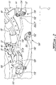
Fig. 2 is a perspective view of an embodiment of a fuel manifold adapter; -
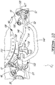
Fig. 3 is a perspective view of another embodiment of a fuel manifold adapter; -
Fig. 4 is a perspective view of a body of the fuel manifold adapter ofFig. 3 , a transfer tube assembly of the fuel manifold adapter having been removed; -
Fig. 5 is a cross-section view taken along the line 5-5 ofFig. 4 ; -
Fig. 6 is a plan view of the fuel manifold adapter ofFig. 3 ; -
Fig. 7 is a cross-section view taken along the line 7-7 ofFig. 6 ; -
Fig. 8 is a perspective view of another embodiment of a fuel manifold adapter; -
Fig. 9 is a cross-section view taken along the line 9-9 ofFig. 8 ; -
Fig. 10 is a perspective view of another embodiment of a fuel manifold adapter, and -
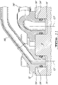
Fig. 11 is a cross-section view taken along the line 11-11 ofFig. 10 . -
Fig. 1 illustrates anaircraft engine 10 of a type preferably provided for use in subsonic flight. According to the illustrated example, theengine 10 is a turboshaft gas turbine engine generally comprising in serial flow communication acompressor 12 for pressurizing the air, acombustor 16 in which the compressed air is mixed with fuel and ignited for generating an annular stream of hot combustion gases, and aturbine section 18 for extracting energy from the combustion gases. There will now be described a fuel manifold adapter 100 (the adapter 100) used in a hot section of the engine, generally shown at L1, in connection with a fuel manifold 20 (Fig. 2 ) of a fuel system of theengine 10 located proximate to thecombustor 16. - Turning now to
Fig. 2 , theadapter 100 is disposed in fluid communication between a fuel inlet nozzle 30 (the inlet nozzle 30) supported by a first mount 40 (orflange 40 of the inlet nozzle 30), and a fuel source 50 (the source 50) for instance provided in the form of a flow divider valve and supported by a second mount 60 (orbracket 60 of the source 50). Theinlet nozzle 30 and thesource 50 are also respectively referred to as a first component and a second component of the fuel system of theengine 10. Via thefirst mount 40 and thesecond mount 60, theinlet nozzle 30 and thesource 50 are respectively mounted at a first mounting point of theengine 10 and at a second mounting point of theengine 10 each being susceptible to thermal growth. Due to the thermal growth occurring as theengine 10 operates, the first and second mounting points move relative to one another with their respective mounted components. In the illustrated embodiment, the first mounting point is on a turbine support case of theengine 10. Thefirst mount 40 is integral to theinlet nozzle 30 and fastened directly to the turbine support case. The second mounting point is located fore of the first mounting point on a peripheral flange of the turbine support case. The second mounting point is also located radially outward of the first mounting point relative to a center line CL of the engine 10 (Fig. 1 ). In other embodiments, the second mounting point is located aft of the first mounting point, for example on a turbine exhaust case of theengine 10. - The
adapter 100 includes abody 110 that is held in position fixedly relative to thesource 50 yet movably relative to theinlet nozzle 30 so as to mitigate stresses imparted to theinlet nozzle 30 by theadapter 100 as thebody 110 moves with thesource 50 to and from theinlet nozzle 30. Thebody 110 is mounted at a third mounting point of theengine 10 via a third mount 150 (orbracket 150 of the body 110), supporting theadapter 100 in position relative to thesource 50. The third mounting point is located aft of the first mounting point, on a peripheral flange of the turbine exhaust case of theengine 10. In other embodiments, thethird mount 150 is integral to the body 110 (as shown for example inFig. 3 ). In yet other embodiments, thebody 110 could be mounted to the source 50 (as shown for example inFig 8 ) and thethird mount 150 could be omitted. - A body-
output interface 112 of thebody 110 movably interfaces with a nozzle-input interface 32 (or upstream end of the inlet nozzle 30) via atransfer tube assembly 120 located at a downstream end (or output end) of theadapter 100. Thetransfer tube assembly 120 may be said to thermally and dynamically decouple the body-output interface 112 and a remainder of theadapter 100 from theinlet nozzle 30. At an upstream end (or input end) of theadapter 100, a body-input interface 114 of thebody 110 fixedly interfaces with a source-output interface 52 (or downstream end of the source 50) via aflanged connector 130 and aconduit 140. Theconduit 140 comprises a rigid tube routed from theflanged connector 130 to thebody 110. Theconduit 140 and theflanged connector 130 can also be described as a rigid supply line which, depending on the embodiment, can form part of theadapter 100 or thesource 50. In this embodiment, the supply line forms part of theadapter 100. Theconduit 140 may be said to rigidly connect theflanged connector 130 and thebody 110 to one another. A fuel path through theadapter 100 extending from thesource 50 to theinlet nozzle 30 is defined successively by theflanged connector 130, theconduit 140, thebody 110 and thetransfer tube assembly 120. The fuel path can consist of a primary fuel path and a secondary fuel path both routed through theadapter 100 separately from one another. The forthcoming description will focus on features of theadapter 100 defining the primary fuel path, as corresponding features of theadapter 100 defining the secondary fuel path are similar, unless stated otherwise. - Still referring to
Fig. 2 , according to the illustrated embodiment, theinlet nozzle 30 interfaces with the first mounting point via thefirst mount 40 so as to orient the nozzle-input interface 32 in a first direction D1 having an axial component parallel to the center line CL of theengine 10. In the first direction D1, the nozzle-input interface 32 extends aft relative to the first mounting point. Thesecond mount 60 holds thesource 50 so as to orient the source-output interface 52 in a second direction D2 having an axial component parallel to the center line CL of theengine 10. The first direction D1 and the direction D2 are in this arrangement parallel to one another and to the center line CL of theengine 10, although other arrangements are possible. Also, the nozzle-input interface 32 and the source-output interface 52 are positioned so as to be radially close to one another relative to the center line CL. This disposition allows theadapter 100 to have a minimal radial footprint as it extends from the source-output interface 52 to the nozzle-input interface 32. As such, theinlet nozzle 30, thesource 50 and theadapter 100 can be made to fit inside a radially outer envelope of theturbine section 18 defined by the outside of the turbine support and exhaust cases up to a radially outer limit of theengine 10. - The
adapter 100 is positioned such that the body-output interface 112 is oriented opposite the first direction D1 across from the nozzle-input interface 32 and the body-input interface 114 is oriented in such a way that theflanged connector 130 rigidly connected thereto is oriented opposite the second direction D2 across from the source-output interface 52. The connections between thebody 110 and theinlet nozzle 30 and between thebody 110 and thesource 50 are directional. Indeed, connecting the body-output interface 112 to the nozzle-input interface 32 via thetransfer tube assembly 120 places the body-input interface 114 in an orientation suitable for it to be connectable to the source-output interface 52 via the supply line. Also, upon the supply line being connected to thebody 110, connecting the body-output interface 112 to the nozzle-input interface 32 orients the flanged connector opposite the second direction D2 in alignment with the source-output interface 52. Conversely, upon the supply line being connected to thebody 110, connecting the body-input interface 114 to the source-output interface 52 via the supply line orients the body-output interface 112 opposite the first direction D1 in alignment with the nozzle-input interface 32. - Upstream of the fuel path, the source-
output interface 52 defines aport 54 from which fuel is flowed to theadapter 100, and to which theflanged connector 130 is fluidly connected. Theflanged connector 130 has aflange 132 and acylinder 134, or cylindrical fitting (similar to that illustrated inFig. 11 with respect to another embodiment) projecting from theflange 132 along a connector axis C. Theport 54 is shaped complementarily to thecylinder 134, in this case a bore extending along a port axis P oriented in the second direction D2 by thesecond mount 60. Upon theflanged connector 130 being connected to theport 54, the connector and port axes C, P are collinear. A fastening means of theflanged connector 130, in this case bolts mechanically coupled to complementary bores defined by theflange 132 and the source-output interface 52, determines an orientation of the supply line with respect to the port axis P as it fastens the supply line to the source-output interface 52. By orienting the supply line together with thebody 110 with respect to the port axis P, theflanged connector 130 is used to locate the body-output interface 112 in alignment with the nozzle-input interface 32. - Referring to
Figs. 3 to 7 , fuel-path defining features will now be described with respect to another embodiment of theadapter 100. Downstream of thesource 50, the primary fuel path is defined by the supply line, i.e., by theflanged connector 130 and theconduit 140, successively. Downstream of the supply line, the primary fuel path is defined afirst passage 116 extending through thebody 110. The body-input interface 114 defines anupstream end 116b of thefirst passage 116 to which theconduit 140 is fluidly connected. The body-output interface 112 of thebody 110 is cylindrical in shape and extends along a body axis B (Fig. 4 ). The body-output interface 112 defines adownstream end 116a of thefirst passage 116 in fluid communication with theupstream end 116b, also referred to as a first body bore 116a of thebody 110. - Downstream of the
source 50, the secondary fuel path is defined by a second supply line, i.e., by a second flanged connector 130' and a second conduit 140', successively. Downstream of the second supply line, the secondary fuel path is defined a second passage 116' extending through thebody 110. The body-input interface 114 defines anupstream end 116b' of the second passage 116' to which the second conduit 140' is fluidly connected. The body-output interface 112 defines adownstream end 116a' of the second passage 116' in fluid communication with theupstream end 116b', also referred to as a second body bore 116a' of thebody 110. - The nozzle-
input interface 32 is located downstream of the body-output interface 112 across from thetransfer tube assembly 120. The nozzle-input interface 32 is cylindrical in shape (as shown inFigs. 6 and7 ), and extends along a longitudinal axis N (Fig. 3 ) oriented in the first direction D1 by thefirst mount 40. A first nozzle bore 34 and a second nozzle bore 34' extend in the nozzle-input interface 32 in fluid communication with thefuel manifold 20. - With reference to
Figs. 6 and7 , characteristics pertaining to thetransfer tube assembly 120 and its relationship with the body-output interface 112 and the nozzle-input interface 32 will now be described. Thetransfer tube assembly 120 includes afirst transfer tube 122 having a rigid, tubular body extending along a longitudinal axis A from afirst tube end 122a to asecond tube end 122b. Thefirst tube end 122a is slidably received by thefirst body bore 116a, whereas thesecond tube end 122b extends to outside thefirst body bore 116a so as to be slidably receivable by the first nozzle bore 34 upon thebody 110 being suitably positioned relative to theinlet nozzle 30. Around either ends 122a, 122b of thetransfer tube 122, O-rings 124 may be mounted for sealing engagement with the corresponding bores, thereby sealing a passage from one bore to the other via thetransfer tube 122. A second transfer tube 122' of thetransfer tube assembly 120 has a rigid, tubular body extending along a longitudinal axis A' from afirst tube end 122a' to asecond tube end 122b'. Thefirst tube end 122a' is slidably received by the second body bore 116a', whereas thesecond tube end 122b' extends to outside the second-body bore 116a' so as to be slidably receivable by the second nozzle bore 34' upon thebody 110 being suitably positioned relative to theinlet nozzle 30. - According to some embodiments, the
transfer tube assembly 120 includes adrain sleeve 126 extending around thetransfer tube 122 from around the body-output interface 112 to around the nozzle-input interface 32. As shown inFig. 6 , O-rings 124 may be mounted around the nozzle-input interface 32 and the body-output interface 112 for sealing engagement with an inner cylindrical surface of thedrain sleeve 126, thereby defining extremities of a sealed cavity inside thedrain sleeve 126. However, thedrain sleeve 126 may be omitted depending on the implementation. - In
Figs. 8 and9 , there is shown yet another embodiment of theadapter 100 implemented in a turboshaft engine. In this embodiment, the first mounting point is located on the turbine support case and the second mounting point is located on the peripheral flange of the turbine support case fore of the first mounting point. The third mounting point is located on thesource 50, i.e., thebody 110 is supported by virtue of its connection to thesource 50. Thebody 110 may be said to be located axially between theinlet nozzle 30 and thesource 50 relative to the center line of theengine 10. The nozzle-input interface 32 extends in the first direction D1 fore relative to the first mounting point and toward the second mounting point. The first direction D1 may thus be said to be toward thesource 50. This arrangement of theinlet nozzle 30 relative to thesource 50 allows for an axially-compact adapter 100. - In this embodiment, first and second
flanged connectors 130, 130' connect to thebody 110 by way of first andsecond conduits 140, 140', provided in the form of hollow and axially short arms that are integral to the body. The first andsecond conduits 140, 140' project from the body-input interface 114 transversely to the body axis B of the body-output interface 112. The nozzle-input interface 32 is closer to afirst port 54 of thesource 50 than to a second port 54' of thesource 50. As such, thefirst conduit 140 is shorter than the second conduit 140'. The firstflanged connector 130 is of a type similar to that described hereinabove, having a first-connector flange 132 and a first-connector cylinder 134, or cylindrical fitting, projecting therefrom along a first-connector axis C for mating engagement with thefirst port 54 along a first-port axis P. The second flanged connector 130' has a second-connector flange 132' and a second-connector bore 134' extending inward thereof along a second-connector axis C'. The second-connector bore 134' is in fluid communication with the second port 54' of the source-output interface 52. Athird transfer tube 122a" of theadapter 100 has afirst end 122a" slidably engaged with the second flanged connector 130' via the second-connector bore 134' along the second-connector axis C', and asecond end 122b" opposite thefirst end 122a" slidably engaged with the source-output interface 52 via the second port 54' along a second-port axis P'. The source-output interface 52 is arranged such that the first-port axis P and the second-port axis P' are generally parallel and aligned with the second direction D2, thereby allowing the firstflanged connector 130 to matingly engage thefirst port 54 simultaneously as the second flanged connector 130' engages with the second port 54' via thethird transfer tube 122". Under certain circumstances, the second-port axis P' may be misaligned (e.g., be at an angle of between 0 to 4 degrees) relative to the first-port axis P, due for example to thermal deformation of thesource 50 and/or to manufacturing tolerances. As the firstflanged connector 130 matingly engages thefirst port 54 with the first-connector axis C collinear to the first-port axis P, thethird transfer tube 122" may tilt relative to the second-connector axis C' and/or to the second-port axis P' to accommodate such misalignment while maintaining the fluid communication between the second port 54' and the second flanged connector 130'. - The present disclosure is not limited to aircraft engines of the turboshaft gas turbine type. For instance, in
Figs. 10 and11 , there is shown an embodiment of thefuel manifold adapter 100 implemented in an engine of the turboprop type. In this embodiment, the first mounting point is located on the turbine support case, the second mounting point is located on the turbine exhaust case at a location spaced aft and circumferentially from the first mounting point, and the third mounting point is located on the peripheral flange of the turbine support case. The nozzle-input interface 32 is oriented in the first direction D1 aft relative to the first mounting point, whereas the source-output interface 52 is oriented in the second direction D2 fore relative to the second mouting point and at an angle relative to the first direction D1. Thus, the first direction D1 and the second direction D2 are neither the same nor opposite one another. Nevertheless, such differences in location and orientation of the nozzle-input interface 32 and the source-output interface 52 are compensated by the supply line being suitably routed therebetween. With thebody 110 located such that the body-output interface 112 is in alignment with the nozzle-input interface 32 opposite the first direction D1, the supply line is routed from the body-input interface 114 so as to extend opposite the second direction D2 as it nears the source-output interface 52. - It shall be noted that the
same body 110 can also be used in connection to theinlet nozzle 30 of a turboshaft engine, as shown inFig. 2 , provided that the supply line is suitably routed between the body-input interface 114 of thebody 110 and the source-output interface 52 of thesource 50 of the turboshaft engine. Theadapter 100 can thus be said to be interchangeably connectable between respective fuel manifolds and fuel sources of different aircraft engine platforms. - The embodiments described in this document provide non-limiting examples of possible implementations of the present technology. Upon review of the present disclosure, a person of ordinary skill in the art will recognize that changes may be made to the embodiments described herein without departing from the scope of the present technology. Indeed, various modifications could be implemented by a person of ordinary skill in the art in view of the present disclosure, which modifications would be within the scope of the present technology.
Claims (15)
- A fuel manifold adapter (100) for a fuel system of an aircraft engine (10), the fuel manifold adapter (100) comprising:a body (110) having:a body-output interface (112) defining a downstream end (116a) of a body passage (116) including a body bore about a bore axis, the body-output interface (112) movably and fluidly connectable to a first component (30) of the fuel system mounted to a first mounting point (40) of the engine (10); anda body-input interface (114) defining an upstream end (116b) of the body passage (116), the body-input interface (116b) rigidly and fluidly connectable to a second component (50) of the fuel system mounted to a second mounting point (60) of the engine (10); anda transfer tube (122) having an upstream-tube end (122a) slidably engaged with the body (110) along the bore axis via the body bore (116a), the transfer tube (122) having a downstream-tube end (122b) opposite the upstream-tube end (122a) slidably engageable along the bore axis with the first component (30), the downstream-tube end (122b) defining a downstream end of the fuel manifold adapter (100) relative to fuel flow through the fuel manifold adapter (100).
- The fuel manifold adapter (100) of claim 1, further comprising a flanged connector (130) fixedly connected to the body (110) via the body-input interface (112) so as to be in fluid communication with the body passage (116), the flanged connector (130) fastenable to the second component (50), the flanged connector (130) defining an upstream end of the fuel manifold adapter (100).
- The fuel manifold adapter (100) of claim 2, further comprising a conduit (140) extending from a downstream-conduit end in fluid communication with the body passage (116) to an upstream-conduit end in fluid communication with the flanged connector (130), the conduit (140) rigidly connecting the flanged connector (130) to the body (110), wherein the conduit (140) optionally includes a rigid tube.
- The fuel manifold adapter (100) of any preceding claim, further comprising a mount (150) for mounting the body (110) to a third mounting point of the engine (10), wherein the mount (150) and the body optionally form a unitary piece.
- The fuel manifold adapter (100) of claim 4, wherein upon the body (110) being mounted to the third mounting point, the body bore (116a) faces a first-component bore (34) of the first component (30).
- The fuel manifold adapter (100) of any preceding claim, wherein upon locating the body bore (116a) opposite a or the first-component bore (34) of the first component (30), the downstream-tube end (122b) is slidably engageable with the first component (30) via the first-component bore (34), and the body (112) is orientable about the bore axis to locate the body-input interface (112) relative to the second component (50).
- The fuel manifold adapter (100) of claim 2 or 3, wherein:the body passage (116) is a first body passage, the body bore (116a) is a first body bore, the bore axis is a first-bore axis and the flanged connector (130) is a first flanged connector;the body-output interface (112) defines a downstream end (116a') of a second body passage (116') including a second body bore about a second-bore axis parallel to the first-bore axis, and the body-input interface (112) defines an upstream end (116b') of the second body passage (116'), andthe fuel manifold adapter (100) includes a second flanged connector (130'), the body-input interface (114) fixedly and fluidly connectable to the second component (50) separately via the first body passage (116) fluidly connected to the first flanged connector (130) and via the second body passage (116') fluidly connected to the second flanged connector (130').
- The fuel manifold adapter (100) of claim 7, wherein the first flanged connector (130) defines a first-connector flange (132) and a first-connector cylinder (134) projecting from the first-connector flange (132) along a first-connector axis (C) parallel to the first-bore axis, the first-connector cylinder (134) matingly engageable with the second component (50) to fluidly connect the first flanged connector (130) to the second component (50).
- The fuel manifold adapter (100) of claim 7 or 8, wherein the second flanged connector (130') defines a second-connector flange (132') and second-connector bore (134') extending inward the second-connector flange (132') along a second-connector axis (C') parallel to the first-bore axis, and the fuel manifold adapter (100) includes a third transfer tube (122a") having opposite ends (122a", 122b") respectively slidably engaged with the second flanged connector (130') via the second-connector bore (134') and slidably engageable with the second component (50) opposite the second flanged connector (130') to fluidly connect the second flanged connector (130') to the second component (50).
- A fuel manifold adapter (100) interchangeably connectable between respective fuel manifolds (20) and fuel sources (50) of different aircraft engine platforms, the fuel manifold adapter (100) comprising:a body (110) having a body-input interface (112) and a body-output interface (114), the body-input interface (112) rigidly connectable to the fuel source (50) of a given one of the different engine platforms so as to locate the body-output interface (114) in alignment with a nozzle-input interface (32) of the fuel manifold (20) of the given one of the engine platforms, the body-output interface (114) slidably engaged with an upstream-tube end (122a) of a linear transfer tube (122) having a downstream-tube end (122b) slidably engaged with the nozzle-input interface (32), the body-output interface (112) and the nozzle-input interface (32) slidably engaged via the linear transfer tube (122) and thermally decoupled via the linear transfer tube (122).
- The fuel manifold adapter (100) of claim 10, further comprising a rigid supply line (130, 140) rigidly connected to the body-input interface (112) and rigidly connectable to the fuel source (50), wherein, optionally, the rigid supply line (130, 140) is routed between a downstream-line end connected to the body-input interface (112) and an upstream-line end (130) connectable to the fuel source (50) such that upon the body-output interface (114) being slidably engaged with the nozzle-input interface (32), the upstream-line end (130) faces a port (54) of the fuel source (50).
- An aircraft engine (10) comprising:a fuel manifold (20) having an inlet nozzle (30), the fuel manifold (20) mounted at a first mounting point (40) of the aircraft engine (10), the inlet nozzle (30) having a nozzle bore (34) facing in a first direction;a fuel source (50) mounted at a second mounting point (60) of the aircraft engine (10), the fuel source (50) having a source bore (52) facing in a second direction; and
the fuel manifold adapter (100) of any preceding claim in fluid communication between the fuel source (50) and the inlet nozzle (30). - The aircraft engine (10) of claim 12, wherein the second mounting point (60) is radially outward of the first mounting point (40) relative to a central axis (CL) of the engine (10), wherein, optionally, the first mounting point (40) is on a turbine support case of the engine (10) and the second mounting point (60) is on a peripheral flange of the turbine support case.
- The aircraft engine (10) of claim 12 or 13, wherein the first mounting point (40) is located aft of the second mounting point (60).
- The aircraft engine (10) of any of claims 12 to 14 , wherein the body (110) is mounted to a third mounting point (150) of the engine (10) located aft of the first mounting point (40), and wherein the third mounting point (150) is optionally on a flange of a turbine exhaust case of the engine (10).
Applications Claiming Priority (1)
| Application Number | Priority Date | Filing Date | Title |
|---|---|---|---|
| US17/363,423 US11867125B2 (en) | 2021-06-30 | 2021-06-30 | Fuel manifold adapter |
Publications (2)
| Publication Number | Publication Date |
|---|---|
| EP4112906A1 true EP4112906A1 (en) | 2023-01-04 |
| EP4112906B1 EP4112906B1 (en) | 2025-06-25 |
Family
ID=81580394
Family Applications (1)
| Application Number | Title | Priority Date | Filing Date |
|---|---|---|---|
| EP22171405.8A Active EP4112906B1 (en) | 2021-06-30 | 2022-05-03 | Fuel manifold adapter |
Country Status (3)
| Country | Link |
|---|---|
| US (2) | US11867125B2 (en) |
| EP (1) | EP4112906B1 (en) |
| CA (1) | CA3157080A1 (en) |
Families Citing this family (1)
| Publication number | Priority date | Publication date | Assignee | Title |
|---|---|---|---|---|
| US12241416B2 (en) * | 2022-07-04 | 2025-03-04 | Pratt & Whitney Canada Corp. | Adaptor for a fuel system of an aircraft engine |
Citations (4)
| Publication number | Priority date | Publication date | Assignee | Title |
|---|---|---|---|---|
| GB2461503A (en) * | 2008-06-30 | 2010-01-06 | Rolls Royce Plc | A sliding joint for a gas turbine engine fuel manifold |
| US20150361897A1 (en) * | 2014-06-13 | 2015-12-17 | Rolls-Royce Plc | Fuel manifold and fuel injector arrangement |
| US20190234310A1 (en) * | 2018-01-29 | 2019-08-01 | Pratt & Whitney Canada Corp. | Segmented internal fuel manifold |
| US20200095935A1 (en) * | 2018-09-26 | 2020-03-26 | Pratt & Whitney Canada Corp. | Fuel manifold assembly |
Family Cites Families (12)
| Publication number | Priority date | Publication date | Assignee | Title |
|---|---|---|---|---|
| US4066281A (en) | 1976-07-16 | 1978-01-03 | Bonis John C De | Porsche automobile oil drain replacement tube |
| US4708371A (en) | 1986-04-09 | 1987-11-24 | Pratt & Whitney Canada Inc. | Coupling for a fuel manifold |
| US7516736B2 (en) * | 2005-05-17 | 2009-04-14 | Honeywell International Inc. | Fuel distributor and mounting system therefor and method of mounting a fuel distributor |
| GB0523573D0 (en) | 2005-11-18 | 2005-12-28 | Airbus Uk Ltd | Aircraft fuel pipe coupling |
| US8490409B2 (en) | 2009-10-01 | 2013-07-23 | Pratt & Whitney Canada Corp. | Bleed air transfer tube |
| US9194297B2 (en) | 2010-12-08 | 2015-11-24 | Parker-Hannifin Corporation | Multiple circuit fuel manifold |
| FR2994217B1 (en) * | 2012-08-06 | 2018-05-04 | Safran Helicopter Engines | MODULAR INJECTION RAMP WITH DOUBLE CIRCUIT |
| US10240534B2 (en) * | 2013-10-25 | 2019-03-26 | United Technologies Corporation | Spherical ball bearing housing |
| US9874351B2 (en) * | 2015-04-14 | 2018-01-23 | General Electric Company | Thermally-coupled fuel manifold |
| DE102016226019B4 (en) | 2016-12-22 | 2022-12-15 | Mahle International Gmbh | Coupling element of a crankcase ventilation device |
| US10808788B2 (en) * | 2017-04-07 | 2020-10-20 | General Electric Company | Damper for a fuel delivery system |
| US20200109643A1 (en) | 2018-10-03 | 2020-04-09 | United Technologies Corporation | Fluid tube assembly for gas turbine engine |
-
2021
- 2021-06-30 US US17/363,423 patent/US11867125B2/en active Active
-
2022
- 2022-04-22 CA CA3157080A patent/CA3157080A1/en active Pending
- 2022-05-03 EP EP22171405.8A patent/EP4112906B1/en active Active
-
2023
- 2023-09-19 US US18/469,711 patent/US12297776B2/en active Active
Patent Citations (4)
| Publication number | Priority date | Publication date | Assignee | Title |
|---|---|---|---|---|
| GB2461503A (en) * | 2008-06-30 | 2010-01-06 | Rolls Royce Plc | A sliding joint for a gas turbine engine fuel manifold |
| US20150361897A1 (en) * | 2014-06-13 | 2015-12-17 | Rolls-Royce Plc | Fuel manifold and fuel injector arrangement |
| US20190234310A1 (en) * | 2018-01-29 | 2019-08-01 | Pratt & Whitney Canada Corp. | Segmented internal fuel manifold |
| US20200095935A1 (en) * | 2018-09-26 | 2020-03-26 | Pratt & Whitney Canada Corp. | Fuel manifold assembly |
Also Published As
| Publication number | Publication date |
|---|---|
| EP4112906B1 (en) | 2025-06-25 |
| US20230003171A1 (en) | 2023-01-05 |
| CA3157080A1 (en) | 2022-12-30 |
| US20240011439A1 (en) | 2024-01-11 |
| US11867125B2 (en) | 2024-01-09 |
| US12297776B2 (en) | 2025-05-13 |
Similar Documents
| Publication | Publication Date | Title |
|---|---|---|
| US12416410B2 (en) | Fuel injectors for multipoint arrays | |
| CA2597592C (en) | Gas turbine combustor and fuel manifold mounting arrangement | |
| US6823676B2 (en) | Mounting for a CMC combustion chamber of a turbomachine by means of flexible connecting sleeves | |
| US9803498B2 (en) | One-piece fuel nozzle for a thrust engine | |
| US20160177872A1 (en) | Exhaust duct | |
| US9140453B2 (en) | Fuel manifold with jumper tubes | |
| CN113137639B (en) | Turboprop engine backflow combustion chamber and turboprop engine | |
| EP3521591A1 (en) | Semented internal fuel manifold | |
| EP3339609A1 (en) | Mounting assembly for gas turbine engine fluid conduit | |
| EP3992434B1 (en) | Service tube assembly for a gas turbine engine | |
| EP3597869B1 (en) | Sealing configuration for a transfer tube assembly to reduce air leakage | |
| US12297776B2 (en) | Fuel manifold adapter | |
| US10132244B2 (en) | Fuel manifold for a gas turbine engine | |
| CN105980663B (en) | Gas flow paths for gas-turbine unit | |
| EP4325036B1 (en) | Fuel assembly for a gas turbine engine | |
| US11919654B2 (en) | Aircraft intake duct with passively movable flow restrictor | |
| CA2764342C (en) | Side-fed shielded internal fuel manifold inlet tube | |
| US7703286B2 (en) | Internal fuel manifold and fuel fairing interface | |
| US10927764B2 (en) | Fuel manifold assembly | |
| US12241416B2 (en) | Adaptor for a fuel system of an aircraft engine | |
| US11352896B2 (en) | Tube assembly for a gas turbine engine | |
| US20220349344A1 (en) | Transfer tube assembly | |
| CN114483321A (en) | Integrated combustion nozzle with integrated head end | |
| US10670178B2 (en) | Slip joint assembly | |
| US12617541B1 (en) | Exhaust case for aircraft engine |
Legal Events
| Date | Code | Title | Description |
|---|---|---|---|
| PUAI | Public reference made under article 153(3) epc to a published international application that has entered the european phase |
Free format text: ORIGINAL CODE: 0009012 |
|
| STAA | Information on the status of an ep patent application or granted ep patent |
Free format text: STATUS: THE APPLICATION HAS BEEN PUBLISHED |
|
| AK | Designated contracting states |
Kind code of ref document: A1 Designated state(s): AL AT BE BG CH CY CZ DE DK EE ES FI FR GB GR HR HU IE IS IT LI LT LU LV MC MK MT NL NO PL PT RO RS SE SI SK SM TR |
|
| STAA | Information on the status of an ep patent application or granted ep patent |
Free format text: STATUS: REQUEST FOR EXAMINATION WAS MADE |
|
| 17P | Request for examination filed |
Effective date: 20230704 |
|
| RBV | Designated contracting states (corrected) |
Designated state(s): AL AT BE BG CH CY CZ DE DK EE ES FI FR GB GR HR HU IE IS IT LI LT LU LV MC MK MT NL NO PL PT RO RS SE SI SK SM TR |
|
| GRAP | Despatch of communication of intention to grant a patent |
Free format text: ORIGINAL CODE: EPIDOSNIGR1 |
|
| STAA | Information on the status of an ep patent application or granted ep patent |
Free format text: STATUS: GRANT OF PATENT IS INTENDED |
|
| RIC1 | Information provided on ipc code assigned before grant |
Ipc: F02C 7/22 20060101AFI20241211BHEP |
|
| INTG | Intention to grant announced |
Effective date: 20250107 |
|
| GRAS | Grant fee paid |
Free format text: ORIGINAL CODE: EPIDOSNIGR3 |
|
| GRAA | (expected) grant |
Free format text: ORIGINAL CODE: 0009210 |
|
| STAA | Information on the status of an ep patent application or granted ep patent |
Free format text: STATUS: THE PATENT HAS BEEN GRANTED |
|
| AK | Designated contracting states |
Kind code of ref document: B1 Designated state(s): AL AT BE BG CH CY CZ DE DK EE ES FI FR GB GR HR HU IE IS IT LI LT LU LV MC MK MT NL NO PL PT RO RS SE SI SK SM TR |
|
| REG | Reference to a national code |
Ref country code: GB Ref legal event code: FG4D |
|
| REG | Reference to a national code |
Ref country code: CH Ref legal event code: EP |
|
| REG | Reference to a national code |
Ref country code: DE Ref legal event code: R096 Ref document number: 602022016306 Country of ref document: DE |
|
| REG | Reference to a national code |
Ref country code: CH Ref legal event code: EP |
|
| REG | Reference to a national code |
Ref country code: IE Ref legal event code: FG4D |
|
| PG25 | Lapsed in a contracting state [announced via postgrant information from national office to epo] |
Ref country code: FI Free format text: LAPSE BECAUSE OF FAILURE TO SUBMIT A TRANSLATION OF THE DESCRIPTION OR TO PAY THE FEE WITHIN THE PRESCRIBED TIME-LIMIT Effective date: 20250625 |
|
| REG | Reference to a national code |
Ref country code: LT Ref legal event code: MG9D |
|
| PG25 | Lapsed in a contracting state [announced via postgrant information from national office to epo] |
Ref country code: NO Free format text: LAPSE BECAUSE OF FAILURE TO SUBMIT A TRANSLATION OF THE DESCRIPTION OR TO PAY THE FEE WITHIN THE PRESCRIBED TIME-LIMIT Effective date: 20250925 Ref country code: GR Free format text: LAPSE BECAUSE OF FAILURE TO SUBMIT A TRANSLATION OF THE DESCRIPTION OR TO PAY THE FEE WITHIN THE PRESCRIBED TIME-LIMIT Effective date: 20250926 |
|
| PG25 | Lapsed in a contracting state [announced via postgrant information from national office to epo] |
Ref country code: BG Free format text: LAPSE BECAUSE OF FAILURE TO SUBMIT A TRANSLATION OF THE DESCRIPTION OR TO PAY THE FEE WITHIN THE PRESCRIBED TIME-LIMIT Effective date: 20250625 |
|
| PG25 | Lapsed in a contracting state [announced via postgrant information from national office to epo] |
Ref country code: HR Free format text: LAPSE BECAUSE OF FAILURE TO SUBMIT A TRANSLATION OF THE DESCRIPTION OR TO PAY THE FEE WITHIN THE PRESCRIBED TIME-LIMIT Effective date: 20250625 |
|
| PG25 | Lapsed in a contracting state [announced via postgrant information from national office to epo] |
Ref country code: RS Free format text: LAPSE BECAUSE OF FAILURE TO SUBMIT A TRANSLATION OF THE DESCRIPTION OR TO PAY THE FEE WITHIN THE PRESCRIBED TIME-LIMIT Effective date: 20250925 |
|
| PG25 | Lapsed in a contracting state [announced via postgrant information from national office to epo] |
Ref country code: LV Free format text: LAPSE BECAUSE OF FAILURE TO SUBMIT A TRANSLATION OF THE DESCRIPTION OR TO PAY THE FEE WITHIN THE PRESCRIBED TIME-LIMIT Effective date: 20250625 |
|
| REG | Reference to a national code |
Ref country code: NL Ref legal event code: MP Effective date: 20250625 |
|
| PG25 | Lapsed in a contracting state [announced via postgrant information from national office to epo] |
Ref country code: NL Free format text: LAPSE BECAUSE OF FAILURE TO SUBMIT A TRANSLATION OF THE DESCRIPTION OR TO PAY THE FEE WITHIN THE PRESCRIBED TIME-LIMIT Effective date: 20250625 |
|
| PG25 | Lapsed in a contracting state [announced via postgrant information from national office to epo] |
Ref country code: PT Free format text: LAPSE BECAUSE OF FAILURE TO SUBMIT A TRANSLATION OF THE DESCRIPTION OR TO PAY THE FEE WITHIN THE PRESCRIBED TIME-LIMIT Effective date: 20251027 |
|
| REG | Reference to a national code |
Ref country code: AT Ref legal event code: MK05 Ref document number: 1806651 Country of ref document: AT Kind code of ref document: T Effective date: 20250625 |
|
| PG25 | Lapsed in a contracting state [announced via postgrant information from national office to epo] |
Ref country code: IS Free format text: LAPSE BECAUSE OF FAILURE TO SUBMIT A TRANSLATION OF THE DESCRIPTION OR TO PAY THE FEE WITHIN THE PRESCRIBED TIME-LIMIT Effective date: 20251025 |
|
| PG25 | Lapsed in a contracting state [announced via postgrant information from national office to epo] |
Ref country code: AT Free format text: LAPSE BECAUSE OF FAILURE TO SUBMIT A TRANSLATION OF THE DESCRIPTION OR TO PAY THE FEE WITHIN THE PRESCRIBED TIME-LIMIT Effective date: 20250625 Ref country code: SM Free format text: LAPSE BECAUSE OF FAILURE TO SUBMIT A TRANSLATION OF THE DESCRIPTION OR TO PAY THE FEE WITHIN THE PRESCRIBED TIME-LIMIT Effective date: 20250625 |
|
| PG25 | Lapsed in a contracting state [announced via postgrant information from national office to epo] |
Ref country code: CZ Free format text: LAPSE BECAUSE OF FAILURE TO SUBMIT A TRANSLATION OF THE DESCRIPTION OR TO PAY THE FEE WITHIN THE PRESCRIBED TIME-LIMIT Effective date: 20250625 |
|
| PG25 | Lapsed in a contracting state [announced via postgrant information from national office to epo] |
Ref country code: PL Free format text: LAPSE BECAUSE OF FAILURE TO SUBMIT A TRANSLATION OF THE DESCRIPTION OR TO PAY THE FEE WITHIN THE PRESCRIBED TIME-LIMIT Effective date: 20250625 |
|
| PG25 | Lapsed in a contracting state [announced via postgrant information from national office to epo] |
Ref country code: EE Free format text: LAPSE BECAUSE OF FAILURE TO SUBMIT A TRANSLATION OF THE DESCRIPTION OR TO PAY THE FEE WITHIN THE PRESCRIBED TIME-LIMIT Effective date: 20250625 |
|
| PG25 | Lapsed in a contracting state [announced via postgrant information from national office to epo] |
Ref country code: SK Free format text: LAPSE BECAUSE OF FAILURE TO SUBMIT A TRANSLATION OF THE DESCRIPTION OR TO PAY THE FEE WITHIN THE PRESCRIBED TIME-LIMIT Effective date: 20250625 |
|
| PG25 | Lapsed in a contracting state [announced via postgrant information from national office to epo] |
Ref country code: ES Free format text: LAPSE BECAUSE OF FAILURE TO SUBMIT A TRANSLATION OF THE DESCRIPTION OR TO PAY THE FEE WITHIN THE PRESCRIBED TIME-LIMIT Effective date: 20250625 |
|
| REG | Reference to a national code |
Ref country code: DE Ref legal event code: R097 Ref document number: 602022016306 Country of ref document: DE |
|
| PG25 | Lapsed in a contracting state [announced via postgrant information from national office to epo] |
Ref country code: DK Free format text: LAPSE BECAUSE OF FAILURE TO SUBMIT A TRANSLATION OF THE DESCRIPTION OR TO PAY THE FEE WITHIN THE PRESCRIBED TIME-LIMIT Effective date: 20250625 |
|
| PG25 | Lapsed in a contracting state [announced via postgrant information from national office to epo] |
Ref country code: IT Free format text: LAPSE BECAUSE OF FAILURE TO SUBMIT A TRANSLATION OF THE DESCRIPTION OR TO PAY THE FEE WITHIN THE PRESCRIBED TIME-LIMIT Effective date: 20250625 |
|
| PLBE | No opposition filed within time limit |
Free format text: ORIGINAL CODE: 0009261 |
|
| STAA | Information on the status of an ep patent application or granted ep patent |
Free format text: STATUS: NO OPPOSITION FILED WITHIN TIME LIMIT |
|
| REG | Reference to a national code |
Ref country code: CH Ref legal event code: L10 Free format text: ST27 STATUS EVENT CODE: U-0-0-L10-L00 (AS PROVIDED BY THE NATIONAL OFFICE) Effective date: 20260507 |
|
| 26N | No opposition filed |
Effective date: 20260326 |
|
| PG25 | Lapsed in a contracting state [announced via postgrant information from national office to epo] |
Ref country code: LT Free format text: LAPSE BECAUSE OF FAILURE TO SUBMIT A TRANSLATION OF THE DESCRIPTION OR TO PAY THE FEE WITHIN THE PRESCRIBED TIME-LIMIT Effective date: 20250625 |
|
| PGFP | Annual fee paid to national office [announced via postgrant information from national office to epo] |
Ref country code: GB Payment date: 20260421 Year of fee payment: 5 |
|
| PGFP | Annual fee paid to national office [announced via postgrant information from national office to epo] |
Ref country code: DE Payment date: 20260421 Year of fee payment: 5 |
|
| PGFP | Annual fee paid to national office [announced via postgrant information from national office to epo] |
Ref country code: FR Payment date: 20260421 Year of fee payment: 5 |
|
| PG25 | Lapsed in a contracting state [announced via postgrant information from national office to epo] |
Ref country code: SE Free format text: LAPSE BECAUSE OF FAILURE TO SUBMIT A TRANSLATION OF THE DESCRIPTION OR TO PAY THE FEE WITHIN THE PRESCRIBED TIME-LIMIT Effective date: 20250625 |