EP4112905A1 - Hybrid electric multiple shaft core - Google Patents
Hybrid electric multiple shaft core Download PDFInfo
- Publication number
- EP4112905A1 EP4112905A1 EP22181380.1A EP22181380A EP4112905A1 EP 4112905 A1 EP4112905 A1 EP 4112905A1 EP 22181380 A EP22181380 A EP 22181380A EP 4112905 A1 EP4112905 A1 EP 4112905A1
- Authority
- EP
- European Patent Office
- Prior art keywords
- turbine
- compressor
- gearbox
- engine
- electric motor
- Prior art date
- Legal status (The legal status is an assumption and is not a legal conclusion. Google has not performed a legal analysis and makes no representation as to the accuracy of the status listed.)
- Pending
Links
Images



Classifications
-
- F—MECHANICAL ENGINEERING; LIGHTING; HEATING; WEAPONS; BLASTING
- F02—COMBUSTION ENGINES; HOT-GAS OR COMBUSTION-PRODUCT ENGINE PLANTS
- F02C—GAS-TURBINE PLANTS; AIR INTAKES FOR JET-PROPULSION PLANTS; CONTROLLING FUEL SUPPLY IN AIR-BREATHING JET-PROPULSION PLANTS
- F02C3/00—Gas-turbine plants characterised by the use of combustion products as the working fluid
- F02C3/04—Gas-turbine plants characterised by the use of combustion products as the working fluid having a turbine driving a compressor
- F02C3/107—Gas-turbine plants characterised by the use of combustion products as the working fluid having a turbine driving a compressor with two or more rotors connected by power transmission
- F02C3/113—Gas-turbine plants characterised by the use of combustion products as the working fluid having a turbine driving a compressor with two or more rotors connected by power transmission with variable power transmission between rotors
-
- F—MECHANICAL ENGINEERING; LIGHTING; HEATING; WEAPONS; BLASTING
- F02—COMBUSTION ENGINES; HOT-GAS OR COMBUSTION-PRODUCT ENGINE PLANTS
- F02C—GAS-TURBINE PLANTS; AIR INTAKES FOR JET-PROPULSION PLANTS; CONTROLLING FUEL SUPPLY IN AIR-BREATHING JET-PROPULSION PLANTS
- F02C7/00—Features, components parts, details or accessories, not provided for in, or of interest apart form groups F02C1/00 - F02C6/00; Air intakes for jet-propulsion plants
- F02C7/36—Power transmission arrangements between the different shafts of the gas turbine plant, or between the gas-turbine plant and the power user
-
- F—MECHANICAL ENGINEERING; LIGHTING; HEATING; WEAPONS; BLASTING
- F02—COMBUSTION ENGINES; HOT-GAS OR COMBUSTION-PRODUCT ENGINE PLANTS
- F02K—JET-PROPULSION PLANTS
- F02K5/00—Plants including an engine, other than a gas turbine, driving a compressor or a ducted fan
-
- F—MECHANICAL ENGINEERING; LIGHTING; HEATING; WEAPONS; BLASTING
- F05—INDEXING SCHEMES RELATING TO ENGINES OR PUMPS IN VARIOUS SUBCLASSES OF CLASSES F01-F04
- F05D—INDEXING SCHEME FOR ASPECTS RELATING TO NON-POSITIVE-DISPLACEMENT MACHINES OR ENGINES, GAS-TURBINES OR JET-PROPULSION PLANTS
- F05D2220/00—Application
- F05D2220/70—Application in combination with
- F05D2220/76—Application in combination with an electrical generator
-
- F—MECHANICAL ENGINEERING; LIGHTING; HEATING; WEAPONS; BLASTING
- F05—INDEXING SCHEMES RELATING TO ENGINES OR PUMPS IN VARIOUS SUBCLASSES OF CLASSES F01-F04
- F05D—INDEXING SCHEME FOR ASPECTS RELATING TO NON-POSITIVE-DISPLACEMENT MACHINES OR ENGINES, GAS-TURBINES OR JET-PROPULSION PLANTS
- F05D2260/00—Function
- F05D2260/40—Transmission of power
- F05D2260/403—Transmission of power through the shape of the drive components
- F05D2260/4031—Transmission of power through the shape of the drive components as in toothed gearing
- F05D2260/40311—Transmission of power through the shape of the drive components as in toothed gearing of the epicyclical, planetary or differential type
-
- F—MECHANICAL ENGINEERING; LIGHTING; HEATING; WEAPONS; BLASTING
- F05—INDEXING SCHEMES RELATING TO ENGINES OR PUMPS IN VARIOUS SUBCLASSES OF CLASSES F01-F04
- F05D—INDEXING SCHEME FOR ASPECTS RELATING TO NON-POSITIVE-DISPLACEMENT MACHINES OR ENGINES, GAS-TURBINES OR JET-PROPULSION PLANTS
- F05D2260/00—Function
- F05D2260/70—Adjusting of angle of incidence or attack of rotating blades
- F05D2260/76—Adjusting of angle of incidence or attack of rotating blades the adjusting mechanism using auxiliary power sources
-
- Y—GENERAL TAGGING OF NEW TECHNOLOGICAL DEVELOPMENTS; GENERAL TAGGING OF CROSS-SECTIONAL TECHNOLOGIES SPANNING OVER SEVERAL SECTIONS OF THE IPC; TECHNICAL SUBJECTS COVERED BY FORMER USPC CROSS-REFERENCE ART COLLECTIONS [XRACs] AND DIGESTS
- Y02—TECHNOLOGIES OR APPLICATIONS FOR MITIGATION OR ADAPTATION AGAINST CLIMATE CHANGE
- Y02T—CLIMATE CHANGE MITIGATION TECHNOLOGIES RELATED TO TRANSPORTATION
- Y02T50/00—Aeronautics or air transport
- Y02T50/60—Efficient propulsion technologies, e.g. for aircraft
Definitions
- Exemplary embodiments of the present disclosure pertain to the art of gas turbine engines, and to aircraft utilizing such engines.
- a traditional gas turbine engine utilizes fuel which is combusted with compressed air to drive a turbine.
- the turbine drives rotation of a compressor which supplies the compressed air to the combustor.
- Other engines are hybrid electric gas turbine engines, which can be selectably powered by electric power from, for example a battery, or by the fuel.
- powering the engine via electrical power may be more efficient than power via the fuel, while during other operational stages, such as takeoff or climb, operation of the engine via liquid fuel may be more efficient or practical.
- electrical power can be used at the same time as the liquid fuel to help drive rotation of the compressor. This may be advantageous when it is desired to increase engine airflow and power more rapidly than can be achieved with fuel alone.
- a hybrid electric engine of an aircraft includes a compressor, a turbine operably connected to the compressor via a variable gear ratio gearbox and a combustor configured to drive the turbine via a flow of combustion products.
- An electric motor is operably connected to the variable gear ratio rear box and configured to input rotational energy into the gearbox. The input of rotational energy into the gearbox from the electric motor changes a rotational speed of one of the compressor or the turbine relative to the other of the compressor or the turbine.
- the input of rotational energy accelerates the compressor relative to the turbine.
- the input of rotational energy decelerates the compressor relative to the turbine.
- the gearbox is located at a central longitudinal axis of the engine.
- the gearbox is located axially forward of the compressor.
- the gearbox is located axially between the compressor and the turbine.
- the gearbox is located remotely from the engine central longitudinal axis.
- the gearbox includes a planetary gear arrangement.
- the electric motor is a variable speed electric motor.
- the engine is a two-spool engine configuration, and the compressor is a high pressure compressor and the turbine is a high pressure turbine.
- a method of operating a hybrid electric engine includes combusting a fuel at a combustor, driving a rotation of a turbine via products of the combustion, and driving rotation of a compressor via rotation of the turbine.
- the turbine and the compressor are operably connected to a variable ratio gearbox. Rotational energy is input from an electric motor into the gearbox and a rotational speed of one of the compressor or the turbine relative to the other of the compressor or the turbine is changed via the input of rotational energy into the gearbox.
- the compressor is accelerated relative to the turbine by the input of rotational energy.
- the rotational speed of the compressor is increased by up to about 30%.
- the compressor is decelerated relative to the turbine by the input of rotational energy.
- a default speed ratio of the compressor to the turbine without input of rotational energy from the electric motor is other than 1:1.
- a speed of the electric motor is varied.
- the rotational energy is transmitted from the electric motor to the gearbox via a tower shaft.
- the gearbox is located axially forward of the compressor.
- the gearbox is located axially between the compressor and the turbine.
- the gearbox is located remotely from the engine central longitudinal axis.
- FIG. 1 schematically illustrates a hybrid electric turbine engine 20.
- the engine 20 is disclosed herein as a two-spool turbofan that generally incorporates a fan section 22, a compressor section 24, a combustor section 26, and a turbine section 28.
- Alternative engines might include other systems or features.
- the fan section 22 drives air along a bypass flow path B in a bypass duct, while the compressor section 24 drives air along a core flow path C for compression and communication into the combustor section 26 then expansion through the turbine section 28.
- FIG. 1 schematically illustrates a hybrid electric turbine engine 20.
- the engine 20 is disclosed herein as a two-spool turbofan that generally incorporates a fan section 22, a compressor section 24, a combustor section 26, and a turbine section 28.
- Alternative engines might include other systems or features.
- the fan section 22 drives air along a bypass flow path B in a bypass duct
- the compressor section 24 drives air along a core flow path C for compression and communication into the combustor section 26 then expansion
- the exemplary engine 20 generally includes a low speed spool 30 and a high speed spool 32 mounted for rotation about an engine central longitudinal axis A relative to an engine static structure.
- the low speed spool 30 generally includes an inner shaft 40 that interconnects a fan 42, a low pressure compressor 44 and a low pressure turbine 46.
- the high speed spool 32 includes an arrangement that interconnects a high pressure compressor 52 and high pressure turbine 54.
- a combustor 56 is arranged in exemplary engine 20 between the high pressure compressor 52 and the high pressure turbine 54.
- the core airflow is compressed by the low pressure compressor 44 then the high pressure compressor 52, mixed and burned with fuel in the combustor 56, then expanded over the high pressure turbine 54 and low pressure turbine 46.
- the turbines 46, 54 rotationally drive the respective low speed spool 30 and high speed spool 32 in response to the expansion.
- the high pressure turbine 54 is driven on a turbine shaft 60, with the turbine shaft 60 surrounding the inner shaft 40 (not shown for clarity).
- the high pressure compressor 52 is similarly driven on a compressor shaft 62.
- a differential or variable gear ratio gearbox 64 for example a planetary gear arrangement or a constantly variable transmission (CVT) arrangement, is connected to both the turbine shaft 60 and the compressor shaft 62, and an electric motor 66 is operably connected to the gearbox 64 via, for example a tower shaft 68.
- the electric motor 66 is connected to the gearbox 64 to selectably help drive the compressor shaft 62.
- the electric motor 66 is connected to a battery 70 as an electrical power source, while in other embodiments another electrical power source may be utilized.
- the electric motor 66 may be powered by, for example, a generator on the turbine section 28 or on the compressor section 24. When energized, the electric motor 66 inputs rotational energy into the gearbox 64 via, for example the tower shaft 68, and accelerates the compressor shaft 62 relative to the turbine shaft 60, and thus accelerates the high pressure compressor 52 relative to the high pressure turbine 54. In this manner, the electric motor's 66 power input may accelerate the high pressure compressor 52 more rapidly than the same power input could accelerate the entire high speed spool 32, because the high speed spool 32 (which includes both the high pressure compressor 52 and the high speed turbine 54) has more inertia than just the high pressure compressor 52.
- this configuration provides for especially rapid thrust or power increase when needed, such as immediately after an engine stall or surge recovery, without high fuel flow (without high turbine power output and high turbine inlet pressure) and the associated risk of another engine stall or surge.
- the electric motor 66 may provide acceleration of any suitable speed, but in some embodiments a rotational speed of the high pressure compressor 52 is within about +/-30% of a rotational speed of the high speed turbine 54. In some embodiments, when no electrical power is applied, the gearbox outputs a ratio of 1:1, meaning that without the application of electrical power the rotational speed of the high pressure compressor 52 equals the rotational speed of the high speed turbine 54. In other embodiments, this default gear ratio may be other than 1:1.
- the electric motor 66 is utilized to accelerate the high pressure compressor 52
- the electric motor 66 may also be an electric machine that can be utilized as a generator to brake or decelerate the high pressure compressor, for example to reduce aerodynamic loading on the compressor blades and aid in stall prevention or initial stall recovery.
- the electric motor 66 is a variable speed motor such that additional variability of the relative speed of the high pressure compressor 52 and the high speed turbine 54 may be achieved by varying the speed of the electric motor 66. In some embodiments, it is desired to actively control a relative speed of the compressor shaft 62 and the turbine shaft 60.
- a compressor speed sensor 82 may be used to detect a compressor shaft speed
- a turbine speed sensor 84 may be used to detect a turbine shaft speed.
- the speed sensors 82, 84 are connected to a controller 86, which is also connected to the electric motor 66.
- the detected compressor shaft speed and turbine shaft speed are compared to a desired compressor shaft speed and turbine speed or compared to a desired speed ratio or the like. If one or more of the measured speeds fall outside of a desired range, the controller 86 directs operation of the electric motor 66 to apply input to the gearbox 64 or stop or change the input of the electric motor 66 to the gearbox 64.
- the electric motor 66 may include a brake mechanism to prevent unnecessary rotation of the electric motor 66 when its input is not desired or needed at the gearbox 64. Such a brake mechanism may be operated by the controller 86 and prevents overheat of the electric motor 66.
- gearbox 64 and electric motor 66 drive on the high speed spool 32 of a gas-turbine engine
- same type of gearbox 64 and electric motor 66 arrangement could advantageously be applied to the low speed spool 30 of a gas-turbine engine, instead of or in addition to the gearbox 64 and electric motor 66 arrangement on the high speed spool 32.
- the gearbox 64 has a planetary gear arrangement.
- the teeth of the gears are omitted in FIG. 6 for clarity.
- the tower shaft 68 would input to a ring gear 76, and the compressor shaft 62 is connected to one or more planet gears 78, while the turbine shaft 60 is connected to a sun gear 80.
- the compressor shaft 62 accelerates while the turbine shaft 60 speed would stay the same.
- meshed gears that defines the relative rotation (speeds) of three different shafts which penetrate the gearbox 64 could be used. Of the three shafts which penetrate the gearbox 62, one would connect to the compressor, one to the turbine, and one to the electric motor 66.
- the turbine shaft 60 and the compressor shaft 62 are coaxial along the engine central longitudinal axis A, with the turbine shaft 60 extending inside of the compressor shaft 62 to connect with the gearbox 64, and the gearbox 64 is located upstream of the high pressure compressor 52.
- the arrangement may vary based on packaging requirements or the like.
- FIG. 3 another configuration is shown in FIG. 3 where the compressor shaft 62 and the turbine shaft 60 are coaxial, with the gearbox 64 located axially between the compressor shaft 62 and the turbine shaft 60.
- the turbine shaft 60 extends from the gearbox 64 in a first axial direction
- the compressor shaft 62 extends from the gearbox 64 is a second, opposite, direction.
- the gearbox 64 is located axially aft of the high pressure turbine 54, with the compressor shaft 62 in this embodiment located radially inboard of the turbine shaft 60 to extend at least partially inside of the turbine shaft 60 and connect to the gearbox 64.
- the gearbox 64 is located remotely from the engine central longitudinal axis A.
- a first drive shaft 72 extends to and is operably connected to the turbine shaft 60
- a second drive shaft 74 extends to and is operably connected to the compressor shaft 62. The remote location of the gearbox 64 further improves flexibility in the packaging of the engine 10.
- variable gear ratio allows for acceleration of, for example the high pressure compressor 52 relative to the high pressure turbine 54, which improves stall recovery performance. Further, such differential speed operation of the high pressure compressor 52 relative to the high pressure turbine 54 has benefits to the engine 10 in the areas of operability, performance, fuel economy and noise reduction.
Landscapes
- Engineering & Computer Science (AREA)
- Chemical & Material Sciences (AREA)
- Combustion & Propulsion (AREA)
- Mechanical Engineering (AREA)
- General Engineering & Computer Science (AREA)
- Structures Of Non-Positive Displacement Pumps (AREA)
Abstract
Description
- Exemplary embodiments of the present disclosure pertain to the art of gas turbine engines, and to aircraft utilizing such engines.
- A traditional gas turbine engine utilizes fuel which is combusted with compressed air to drive a turbine. The turbine, in turn, drives rotation of a compressor which supplies the compressed air to the combustor. Other engines are hybrid electric gas turbine engines, which can be selectably powered by electric power from, for example a battery, or by the fuel. During certain operational stages or under certain conditions, such as taxi or cruise operation, powering the engine via electrical power may be more efficient than power via the fuel, while during other operational stages, such as takeoff or climb, operation of the engine via liquid fuel may be more efficient or practical. In addition, electrical power can be used at the same time as the liquid fuel to help drive rotation of the compressor. This may be advantageous when it is desired to increase engine airflow and power more rapidly than can be achieved with fuel alone.
- In one embodiment, a hybrid electric engine of an aircraft includes a compressor, a turbine operably connected to the compressor via a variable gear ratio gearbox and a combustor configured to drive the turbine via a flow of combustion products. An electric motor is operably connected to the variable gear ratio rear box and configured to input rotational energy into the gearbox. The input of rotational energy into the gearbox from the electric motor changes a rotational speed of one of the compressor or the turbine relative to the other of the compressor or the turbine.
- Additionally or alternatively, in this or other embodiments the input of rotational energy accelerates the compressor relative to the turbine.
- Additionally or alternatively, in this or other embodiments the input of rotational energy decelerates the compressor relative to the turbine.
- Additionally or alternatively, in this or other embodiments the gearbox is located at a central longitudinal axis of the engine.
- Additionally or alternatively, in this or other embodiments the gearbox is located axially forward of the compressor.
- Additionally or alternatively, in this or other embodiments the gearbox is located axially between the compressor and the turbine.
- Additionally or alternatively, in this or other embodiments the gearbox is located remotely from the engine central longitudinal axis.
- Additionally or alternatively, in this or other embodiments in the gearbox includes a planetary gear arrangement.
- Additionally or alternatively, in this or other embodiments the electric motor is a variable speed electric motor.
- Additionally or alternatively, in this or other embodiments the engine is a two-spool engine configuration, and the compressor is a high pressure compressor and the turbine is a high pressure turbine.
- In another embodiment, a method of operating a hybrid electric engine includes combusting a fuel at a combustor, driving a rotation of a turbine via products of the combustion, and driving rotation of a compressor via rotation of the turbine. The turbine and the compressor are operably connected to a variable ratio gearbox. Rotational energy is input from an electric motor into the gearbox and a rotational speed of one of the compressor or the turbine relative to the other of the compressor or the turbine is changed via the input of rotational energy into the gearbox.
- Additionally or alternatively, in this or other embodiments the compressor is accelerated relative to the turbine by the input of rotational energy.
- Additionally or alternatively, in this or other embodiments the rotational speed of the compressor is increased by up to about 30%.
- Additionally or alternatively, in this or other embodiments the compressor is decelerated relative to the turbine by the input of rotational energy.
- Additionally or alternatively, in this or other embodiments a default speed ratio of the compressor to the turbine without input of rotational energy from the electric motor is other than 1:1.
- Additionally or alternatively, in this or other embodiments a speed of the electric motor is varied.
- Additionally or alternatively, in this or other embodiments the rotational energy is transmitted from the electric motor to the gearbox via a tower shaft.
- Additionally or alternatively, in this or other embodiments the gearbox is located axially forward of the compressor.
- Additionally or alternatively, in this or other embodiments the gearbox is located axially between the compressor and the turbine.
- Additionally or alternatively, in this or other embodiments the gearbox is located remotely from the engine central longitudinal axis.
- The following descriptions should not be considered limiting in any way. With reference to the accompanying drawings, like elements are numbered alike:
-
FIG. 1 is a schematic illustration of an embodiment of a hybrid electric turbine engine; -
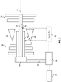
FIG. 2 is a schematic illustration of an embodiment of a variable differential gearbox arrangement of a hybrid electric turbine engine; -
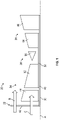
FIG. 3 is a schematic illustration of another embodiment of a variable differential gearbox arrangement of a hybrid electric turbine engine; -
FIG. 4 is a schematic illustration of yet another embodiment of a variable differential gearbox arrangement of a hybrid electric turbine engine; -
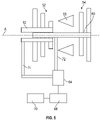
FIG. 5 is a schematic illustration of still another embodiment of a variable differential gearbox arrangement of a hybrid electric turbine engine; and -
FIG. 6 is a schematic illustration of a planetary gearbox arrangement. - A detailed description of one or more embodiments of the disclosed apparatus and method are presented herein by way of exemplification and not limitation with reference to the Figures.
-
FIG. 1 schematically illustrates a hybridelectric turbine engine 20. Theengine 20 is disclosed herein as a two-spool turbofan that generally incorporates afan section 22, acompressor section 24, acombustor section 26, and aturbine section 28. Alternative engines might include other systems or features. Thefan section 22 drives air along a bypass flow path B in a bypass duct, while thecompressor section 24 drives air along a core flow path C for compression and communication into thecombustor section 26 then expansion through theturbine section 28. Although depicted as a two-spool turbofan gas turbine engine in the disclosed non-limiting embodiment, it should be understood that the concepts described herein are not limited to use with two-spool turbofans as the teachings may be applied to other types of turbine engines including three-spool architectures. - The
exemplary engine 20 generally includes alow speed spool 30 and ahigh speed spool 32 mounted for rotation about an engine central longitudinal axis A relative to an engine static structure. Thelow speed spool 30 generally includes aninner shaft 40 that interconnects afan 42, alow pressure compressor 44 and alow pressure turbine 46. Thehigh speed spool 32 includes an arrangement that interconnects ahigh pressure compressor 52 andhigh pressure turbine 54. Acombustor 56 is arranged inexemplary engine 20 between thehigh pressure compressor 52 and thehigh pressure turbine 54. In one mode of operation, the core airflow is compressed by thelow pressure compressor 44 then thehigh pressure compressor 52, mixed and burned with fuel in thecombustor 56, then expanded over thehigh pressure turbine 54 andlow pressure turbine 46. Theturbines low speed spool 30 andhigh speed spool 32 in response to the expansion. - Referring now to
FIG. 2 , Thehigh pressure turbine 54 is driven on aturbine shaft 60, with theturbine shaft 60 surrounding the inner shaft 40 (not shown for clarity). Thehigh pressure compressor 52 is similarly driven on acompressor shaft 62. A differential or variablegear ratio gearbox 64, for example a planetary gear arrangement or a constantly variable transmission (CVT) arrangement, is connected to both theturbine shaft 60 and thecompressor shaft 62, and anelectric motor 66 is operably connected to thegearbox 64 via, for example atower shaft 68. Theelectric motor 66 is connected to thegearbox 64 to selectably help drive thecompressor shaft 62. In some embodiments, theelectric motor 66 is connected to abattery 70 as an electrical power source, while in other embodiments another electrical power source may be utilized. For example, theelectric motor 66 may be powered by, for example, a generator on theturbine section 28 or on thecompressor section 24. When energized, theelectric motor 66 inputs rotational energy into thegearbox 64 via, for example thetower shaft 68, and accelerates thecompressor shaft 62 relative to theturbine shaft 60, and thus accelerates thehigh pressure compressor 52 relative to thehigh pressure turbine 54. In this manner, the electric motor's 66 power input may accelerate thehigh pressure compressor 52 more rapidly than the same power input could accelerate the entirehigh speed spool 32, because the high speed spool 32 (which includes both thehigh pressure compressor 52 and the high speed turbine 54) has more inertia than just thehigh pressure compressor 52. Thus this configuration provides for especially rapid thrust or power increase when needed, such as immediately after an engine stall or surge recovery, without high fuel flow (without high turbine power output and high turbine inlet pressure) and the associated risk of another engine stall or surge. - The
electric motor 66 may provide acceleration of any suitable speed, but in some embodiments a rotational speed of thehigh pressure compressor 52 is within about +/-30% of a rotational speed of thehigh speed turbine 54. In some embodiments, when no electrical power is applied, the gearbox outputs a ratio of 1:1, meaning that without the application of electrical power the rotational speed of thehigh pressure compressor 52 equals the rotational speed of thehigh speed turbine 54. In other embodiments, this default gear ratio may be other than 1:1. While in some embodiments, theelectric motor 66 is utilized to accelerate thehigh pressure compressor 52, theelectric motor 66 may also be an electric machine that can be utilized as a generator to brake or decelerate the high pressure compressor, for example to reduce aerodynamic loading on the compressor blades and aid in stall prevention or initial stall recovery. In some embodiments, theelectric motor 66 is a variable speed motor such that additional variability of the relative speed of thehigh pressure compressor 52 and thehigh speed turbine 54 may be achieved by varying the speed of theelectric motor 66. In some embodiments, it is desired to actively control a relative speed of thecompressor shaft 62 and theturbine shaft 60. As such, acompressor speed sensor 82 may be used to detect a compressor shaft speed, and aturbine speed sensor 84 may be used to detect a turbine shaft speed. Thespeed sensors controller 86, which is also connected to theelectric motor 66. The detected compressor shaft speed and turbine shaft speed are compared to a desired compressor shaft speed and turbine speed or compared to a desired speed ratio or the like. If one or more of the measured speeds fall outside of a desired range, thecontroller 86 directs operation of theelectric motor 66 to apply input to thegearbox 64 or stop or change the input of theelectric motor 66 to thegearbox 64. Further, theelectric motor 66 may include a brake mechanism to prevent unnecessary rotation of theelectric motor 66 when its input is not desired or needed at thegearbox 64. Such a brake mechanism may be operated by thecontroller 86 and prevents overheat of theelectric motor 66. - Although the embodiment provided above describes a
differential gearbox 64 andelectric motor 66 drive on thehigh speed spool 32 of a gas-turbine engine, the same type ofgearbox 64 andelectric motor 66 arrangement could advantageously be applied to thelow speed spool 30 of a gas-turbine engine, instead of or in addition to thegearbox 64 andelectric motor 66 arrangement on thehigh speed spool 32. - In some embodiments, such as shown in
FIG. 6 , thegearbox 64 has a planetary gear arrangement. The teeth of the gears are omitted inFIG. 6 for clarity. In such a planetary gear arrangement, thetower shaft 68 would input to aring gear 76, and thecompressor shaft 62 is connected to one or more planet gears 78, while theturbine shaft 60 is connected to asun gear 80. Thus, when power is input to thering gear 76 from theelectric motor 66, thecompressor shaft 62 accelerates while theturbine shaft 60 speed would stay the same. One skilled in the art, however, will readily appreciate that such an arrangement is merely exemplary, and that many other arrangements are possible. Any arrangement of meshed gears that defines the relative rotation (speeds) of three different shafts which penetrate thegearbox 64 could be used. Of the three shafts which penetrate thegearbox 62, one would connect to the compressor, one to the turbine, and one to theelectric motor 66. - In some embodiments, such as shown in
FIG. 2 , theturbine shaft 60 and thecompressor shaft 62 are coaxial along the engine central longitudinal axis A, with theturbine shaft 60 extending inside of thecompressor shaft 62 to connect with thegearbox 64, and thegearbox 64 is located upstream of thehigh pressure compressor 52. The arrangement, however, may vary based on packaging requirements or the like. For example, another configuration is shown inFIG. 3 where thecompressor shaft 62 and theturbine shaft 60 are coaxial, with thegearbox 64 located axially between thecompressor shaft 62 and theturbine shaft 60. In this embodiment, theturbine shaft 60 extends from thegearbox 64 in a first axial direction, and thecompressor shaft 62 extends from thegearbox 64 is a second, opposite, direction. In other embodiments, such as shown inFIG. 4 , thegearbox 64 is located axially aft of thehigh pressure turbine 54, with thecompressor shaft 62 in this embodiment located radially inboard of theturbine shaft 60 to extend at least partially inside of theturbine shaft 60 and connect to thegearbox 64. Referring now toFIG. 5 , in other embodiments, thegearbox 64 is located remotely from the engine central longitudinal axis A. For example, in some embodiments afirst drive shaft 72 extends to and is operably connected to theturbine shaft 60, and asecond drive shaft 74 extends to and is operably connected to thecompressor shaft 62. The remote location of thegearbox 64 further improves flexibility in the packaging of the engine 10. - While the present disclosure is described in the context of a two-spool engine 10, one skilled in the art will readily appreciate that the configurations disclosed herein may be readily applied to a single spool or other multiple spool engines, such as a three spool engine. The variable gear ratio allows for acceleration of, for example the
high pressure compressor 52 relative to thehigh pressure turbine 54, which improves stall recovery performance. Further, such differential speed operation of thehigh pressure compressor 52 relative to thehigh pressure turbine 54 has benefits to the engine 10 in the areas of operability, performance, fuel economy and noise reduction. - The term "about" is intended to include the degree of error associated with measurement of the particular quantity based upon the equipment available at the time of filing the application. For example, "about" can include a range of ± 8% or 5%, or 2% of a given value.
- The terminology used herein is for the purpose of describing particular embodiments only and is not intended to be limiting of the present disclosure. As used herein, the singular forms "a", "an" and "the" are intended to include the plural forms as well, unless the context clearly indicates otherwise. It will be further understood that the terms "comprises" and/or "comprising," when used in this specification, specify the presence of stated features, integers, steps, operations, elements, and/or components, but do not preclude the presence or addition of one or more other features, integers, steps, operations, element components, and/or groups thereof.
- While the present disclosure has been described with reference to an exemplary embodiment or embodiments, it will be understood by those skilled in the art that various changes may be made and equivalents may be substituted for elements thereof without departing from the scope of the present disclosure. In addition, many modifications may be made to adapt a particular situation or material to the teachings of the present disclosure without departing from the essential scope thereof. Therefore, it is intended that the present disclosure not be limited to the particular embodiment disclosed as the best mode contemplated for carrying out this present disclosure, but that the present disclosure will include all embodiments falling within the scope of the claims.
Claims (15)
- A hybrid electric engine (20) of an aircraft, comprising:a compressor (52);a turbine (54) operably connected to the compressor (52) via a variable gear ratio gearbox (64);a combustor (56) configured to drive the turbine (54) via a flow of combustion products; andan electric motor (66) operably connected to the variable gear ratio gearbox (64) and configured to input rotational energy into the gearbox (64);wherein the input of rotational energy into the gearbox (64) from the electric motor (66) changes a rotational speed of one of the compressor (52) or the turbine (54) relative to the other of the compressor (52) or the turbine (54).
- The hybrid electric engine of claim 1, wherein:the input of rotational energy accelerates the compressor (52) relative to the turbine (54); orthe input of rotational energy decelerates the compressor (52) relative to the turbine (54).
- The hybrid electric engine of any preceding claim, wherein in the gearbox (64) includes a planetary gear arrangement.
- The hybrid electric engine of any preceding claim, wherein the electric motor (66) is a variable speed electric motor.
- The hybrid electric engine of any preceding claim, wherein the engine (20) is a two-spool engine configuration, the compressor (52) is a high pressure compressor (52) and the turbine (54) is a high pressure turbine (54).
- A method of operating a hybrid electric engine (20), comprising:combusting a fuel at a combustor (56);driving a rotation of a turbine (54) via products of the combustion;driving rotation of a compressor (52) via rotation of the turbine (54), the turbine (54) and the compressor (52) operably connected to a variable ratio gearbox (64);inputting rotational energy from an electric motor (66) into the gearbox (64);changing a rotational speed of one of the compressor (52) or the turbine (54) relative to the other of the compressor (52) or the turbine (54) via the input of rotational energy into the gearbox (64).
- The method of claim 6, further comprising:accelerating the compressor (52) relative to the turbine (54) by the input of rotational energy; ordecelerating the compressor (52) relative to the turbine (54) by the input of rotational energy.
- The method of claim 6 or 7, wherein the rotational speed of the compressor (52) is increased by up to about 30%.
- The method of claim 6, 7 or 8, wherein a default speed ratio of the compressor (52) to the turbine (54) without input of rotational energy from the electric motor (66) is other than 1:1.
- The method of any of claims 6 to 9, further comprising varying a speed of the electric motor (66).
- The method of any of claims 6 to 10, further comprising transmitting the rotational energy from the electric motor (66) to the gearbox (64) via a tower shaft (68).
- The hybrid electric engine or method of any preceding claim, wherein the gearbox (64) is disposed at a central longitudinal axis (A) of the engine (20).
- The hybrid electric engine or method of claim 12, wherein the gearbox (64) is located axially forward of the compressor (52).
- The hybrid electric engine or method of claim 12, wherein the gearbox (64) is located axially between the compressor (52) and the turbine (54).
- The hybrid electric engine or method of any of claims 1 to 11, wherein the gearbox (64) is located remotely from a engine central longitudinal axis (A).
Applications Claiming Priority (1)
| Application Number | Priority Date | Filing Date | Title |
|---|---|---|---|
| US17/359,891 US12480450B2 (en) | 2021-06-28 | 2021-06-28 | Hybrid electric multiple shaft core |
Publications (1)
| Publication Number | Publication Date |
|---|---|
| EP4112905A1 true EP4112905A1 (en) | 2023-01-04 |
Family
ID=82321567
Family Applications (1)
| Application Number | Title | Priority Date | Filing Date |
|---|---|---|---|
| EP22181380.1A Pending EP4112905A1 (en) | 2021-06-28 | 2022-06-27 | Hybrid electric multiple shaft core |
Country Status (2)
| Country | Link |
|---|---|
| US (1) | US12480450B2 (en) |
| EP (1) | EP4112905A1 (en) |
Families Citing this family (4)
| Publication number | Priority date | Publication date | Assignee | Title |
|---|---|---|---|---|
| US12384556B2 (en) | 2023-01-25 | 2025-08-12 | Rolls-Royce Corporation | Hybrid propulsion systems with power sharing |
| US12371177B2 (en) * | 2023-01-25 | 2025-07-29 | Rolls-Royce Corporation | Hybrid propulsion systems with power sharing |
| US12351323B2 (en) * | 2023-02-02 | 2025-07-08 | Rtx Corporation | Hybrid electric engine and nacelle system |
| US12553380B2 (en) | 2024-01-24 | 2026-02-17 | Rtx Corporation | Constant speed accessory gearbox for turbine engine |
Citations (5)
| Publication number | Priority date | Publication date | Assignee | Title |
|---|---|---|---|---|
| US20140290265A1 (en) * | 2013-01-30 | 2014-10-02 | Pratt & Whitney Canada Corp. | Gas turbine engine with transmission |
| WO2020058652A1 (en) * | 2018-09-21 | 2020-03-26 | Safran Aircraft Engines | Turbo-reactor comprising a power supply device |
| US20200386188A1 (en) * | 2019-06-05 | 2020-12-10 | United Technologies Corporation | Hybrid turbofan with differential electrical and mechanical power transfer |
| BE1027469A1 (en) * | 2019-08-01 | 2021-02-23 | Safran Aero Boosters Sa | TURBOMACHINE ARCHITECTURE WITH ACCELERATED BOOSTER |
| US20210054788A1 (en) * | 2019-08-23 | 2021-02-25 | United Technologies Corporation | Augmented drive of compressors via differential and multistage turbine |
Family Cites Families (11)
| Publication number | Priority date | Publication date | Assignee | Title |
|---|---|---|---|---|
| US8192143B2 (en) * | 2008-05-21 | 2012-06-05 | United Technologies Corporation | Gearbox assembly |
| GB201219544D0 (en) * | 2012-10-31 | 2012-12-12 | Rolls Royce Deutschland | Geared compressor for gas turbine engine |
| GB2547674A (en) | 2016-02-25 | 2017-08-30 | Rolls Royce Plc | Gas turbine engine |
| US10273883B2 (en) * | 2016-02-26 | 2019-04-30 | The Boeing Company | Engine accessory drives systems and methods |
| BE1026407B1 (en) | 2018-06-22 | 2020-01-28 | Safran Aero Boosters Sa | HYBRID TRANSMISSION TURBOMACHINE |
| US20200095930A1 (en) * | 2018-09-20 | 2020-03-26 | Honeywell International Inc. | Variable gear ratio gas turbine engine system |
| FR3086348B1 (en) * | 2018-09-21 | 2020-12-04 | Safran Aircraft Engines | REDUCER TURBOREACTOR |
| WO2020190344A2 (en) | 2019-03-18 | 2020-09-24 | United Technologies Advanced Projects Inc. | Architectures for hybrid-electric propulsion |
| US11333077B2 (en) * | 2019-05-06 | 2022-05-17 | The Boeing Company | Systems and methods for transferring mechanical power in a turbine engine |
| US11428171B2 (en) * | 2019-12-06 | 2022-08-30 | General Electric Company | Electric machine assistance for multi-spool turbomachine operation and control |
| DE102020206958A1 (en) * | 2020-06-03 | 2021-08-19 | Mtu Friedrichshafen Gmbh | Turbine device |
-
2021
- 2021-06-28 US US17/359,891 patent/US12480450B2/en active Active
-
2022
- 2022-06-27 EP EP22181380.1A patent/EP4112905A1/en active Pending
Patent Citations (5)
| Publication number | Priority date | Publication date | Assignee | Title |
|---|---|---|---|---|
| US20140290265A1 (en) * | 2013-01-30 | 2014-10-02 | Pratt & Whitney Canada Corp. | Gas turbine engine with transmission |
| WO2020058652A1 (en) * | 2018-09-21 | 2020-03-26 | Safran Aircraft Engines | Turbo-reactor comprising a power supply device |
| US20200386188A1 (en) * | 2019-06-05 | 2020-12-10 | United Technologies Corporation | Hybrid turbofan with differential electrical and mechanical power transfer |
| BE1027469A1 (en) * | 2019-08-01 | 2021-02-23 | Safran Aero Boosters Sa | TURBOMACHINE ARCHITECTURE WITH ACCELERATED BOOSTER |
| US20210054788A1 (en) * | 2019-08-23 | 2021-02-25 | United Technologies Corporation | Augmented drive of compressors via differential and multistage turbine |
Also Published As
| Publication number | Publication date |
|---|---|
| US20220412268A1 (en) | 2022-12-29 |
| US12480450B2 (en) | 2025-11-25 |
Similar Documents
| Publication | Publication Date | Title |
|---|---|---|
| EP4112905A1 (en) | Hybrid electric multiple shaft core | |
| EP3748146B1 (en) | Hybrid turbofan with differential electrical and mechanical power transfer | |
| US12065973B2 (en) | Electric enhanced transmission for multi-spool load-sharing turbofan engine | |
| EP3282093B1 (en) | Geared turbofan with low spool power extraction | |
| US8324746B2 (en) | Variable drive gas turbine engine | |
| EP3643906B1 (en) | Engine for an aircraft | |
| EP3039276B1 (en) | Three spool geared turbofan with low pressure compressor drive gear system and mechanical controller | |
| EP1831521B1 (en) | Variable fan inlet guide vane assembly, turbine engine with such an assembly and corresponding controlling method | |
| CN112664320A (en) | Gas turbine engine supercharger configuration and method of operation | |
| EP3800342B1 (en) | Superposition gearbox for engine performance | |
| CN101230802B (en) | Variable coupling of high pressure rotor and low pressure rotor of turbofan engine | |
| EP3987166B1 (en) | Gearbox for boost spool turbine engine | |
| US9347373B2 (en) | Gas turbine engine with transmission | |
| EP1980732A2 (en) | Power take-off system and gas turbine assembly including same | |
| EP3693581B1 (en) | Dual spool power extraction with superposition gearbox | |
| EP3327276A1 (en) | Gas turbine engine | |
| EP3693580A1 (en) | Gearbox assembly | |
| EP3715668A1 (en) | Transmission for low spool of gas turbine engine | |
| EP4108904A1 (en) | Hybrid electric engine including auxiliary compressor | |
| EP4624736A1 (en) | Electric compressor stage for a gas turbine engine | |
| GB2626331A (en) | Method of controlling a gas turbine engine | |
| GB2589374A (en) | Electronic engine controller |
Legal Events
| Date | Code | Title | Description |
|---|---|---|---|
| PUAI | Public reference made under article 153(3) epc to a published international application that has entered the european phase |
Free format text: ORIGINAL CODE: 0009012 |
|
| STAA | Information on the status of an ep patent application or granted ep patent |
Free format text: STATUS: THE APPLICATION HAS BEEN PUBLISHED |
|
| AK | Designated contracting states |
Kind code of ref document: A1 Designated state(s): AL AT BE BG CH CY CZ DE DK EE ES FI FR GB GR HR HU IE IS IT LI LT LU LV MC MK MT NL NO PL PT RO RS SE SI SK SM TR |
|
| STAA | Information on the status of an ep patent application or granted ep patent |
Free format text: STATUS: REQUEST FOR EXAMINATION WAS MADE |
|
| 17P | Request for examination filed |
Effective date: 20230704 |
|
| RBV | Designated contracting states (corrected) |
Designated state(s): AL AT BE BG CH CY CZ DE DK EE ES FI FR GB GR HR HU IE IS IT LI LT LU LV MC MK MT NL NO PL PT RO RS SE SI SK SM TR |
|
| RAP3 | Party data changed (applicant data changed or rights of an application transferred) |
Owner name: RTX CORPORATION |
|
| STAA | Information on the status of an ep patent application or granted ep patent |
Free format text: STATUS: EXAMINATION IS IN PROGRESS |
|
| 17Q | First examination report despatched |
Effective date: 20241219 |