EP4112891B1 - A muffler comprising one or more sensor ports - Google Patents
A muffler comprising one or more sensor ports Download PDFInfo
- Publication number
- EP4112891B1 EP4112891B1 EP21183001.3A EP21183001A EP4112891B1 EP 4112891 B1 EP4112891 B1 EP 4112891B1 EP 21183001 A EP21183001 A EP 21183001A EP 4112891 B1 EP4112891 B1 EP 4112891B1
- Authority
- EP
- European Patent Office
- Prior art keywords
- muffler
- plate
- wall
- washer
- opening
- Prior art date
- Legal status (The legal status is an assumption and is not a legal conclusion. Google has not performed a legal analysis and makes no representation as to the accuracy of the status listed.)
- Active
Links
Images



Classifications
-
- F—MECHANICAL ENGINEERING; LIGHTING; HEATING; WEAPONS; BLASTING
- F01—MACHINES OR ENGINES IN GENERAL; ENGINE PLANTS IN GENERAL; STEAM ENGINES
- F01N—GAS-FLOW SILENCERS OR EXHAUST APPARATUS FOR MACHINES OR ENGINES IN GENERAL; GAS-FLOW SILENCERS OR EXHAUST APPARATUS FOR INTERNAL-COMBUSTION ENGINES
- F01N13/00—Exhaust or silencing apparatus characterised by constructional features
-
- F—MECHANICAL ENGINEERING; LIGHTING; HEATING; WEAPONS; BLASTING
- F01—MACHINES OR ENGINES IN GENERAL; ENGINE PLANTS IN GENERAL; STEAM ENGINES
- F01N—GAS-FLOW SILENCERS OR EXHAUST APPARATUS FOR MACHINES OR ENGINES IN GENERAL; GAS-FLOW SILENCERS OR EXHAUST APPARATUS FOR INTERNAL-COMBUSTION ENGINES
- F01N1/00—Silencing apparatus characterised by method of silencing
- F01N1/02—Silencing apparatus characterised by method of silencing by using resonance
-
- F—MECHANICAL ENGINEERING; LIGHTING; HEATING; WEAPONS; BLASTING
- F01—MACHINES OR ENGINES IN GENERAL; ENGINE PLANTS IN GENERAL; STEAM ENGINES
- F01N—GAS-FLOW SILENCERS OR EXHAUST APPARATUS FOR MACHINES OR ENGINES IN GENERAL; GAS-FLOW SILENCERS OR EXHAUST APPARATUS FOR INTERNAL-COMBUSTION ENGINES
- F01N11/00—Monitoring or diagnostic devices for exhaust-gas treatment apparatus
-
- F—MECHANICAL ENGINEERING; LIGHTING; HEATING; WEAPONS; BLASTING
- F01—MACHINES OR ENGINES IN GENERAL; ENGINE PLANTS IN GENERAL; STEAM ENGINES
- F01N—GAS-FLOW SILENCERS OR EXHAUST APPARATUS FOR MACHINES OR ENGINES IN GENERAL; GAS-FLOW SILENCERS OR EXHAUST APPARATUS FOR INTERNAL-COMBUSTION ENGINES
- F01N13/00—Exhaust or silencing apparatus characterised by constructional features
- F01N13/008—Mounting or arrangement of exhaust sensors in or on exhaust apparatus
-
- F—MECHANICAL ENGINEERING; LIGHTING; HEATING; WEAPONS; BLASTING
- F01—MACHINES OR ENGINES IN GENERAL; ENGINE PLANTS IN GENERAL; STEAM ENGINES
- F01N—GAS-FLOW SILENCERS OR EXHAUST APPARATUS FOR MACHINES OR ENGINES IN GENERAL; GAS-FLOW SILENCERS OR EXHAUST APPARATUS FOR INTERNAL-COMBUSTION ENGINES
- F01N13/00—Exhaust or silencing apparatus characterised by constructional features
- F01N13/14—Exhaust or silencing apparatus characterised by constructional features having thermal insulation
- F01N13/141—Double-walled exhaust pipes or housings
-
- F—MECHANICAL ENGINEERING; LIGHTING; HEATING; WEAPONS; BLASTING
- F01—MACHINES OR ENGINES IN GENERAL; ENGINE PLANTS IN GENERAL; STEAM ENGINES
- F01N—GAS-FLOW SILENCERS OR EXHAUST APPARATUS FOR MACHINES OR ENGINES IN GENERAL; GAS-FLOW SILENCERS OR EXHAUST APPARATUS FOR INTERNAL-COMBUSTION ENGINES
- F01N13/00—Exhaust or silencing apparatus characterised by constructional features
- F01N13/16—Selection of particular materials
-
- F—MECHANICAL ENGINEERING; LIGHTING; HEATING; WEAPONS; BLASTING
- F01—MACHINES OR ENGINES IN GENERAL; ENGINE PLANTS IN GENERAL; STEAM ENGINES
- F01N—GAS-FLOW SILENCERS OR EXHAUST APPARATUS FOR MACHINES OR ENGINES IN GENERAL; GAS-FLOW SILENCERS OR EXHAUST APPARATUS FOR INTERNAL-COMBUSTION ENGINES
- F01N13/00—Exhaust or silencing apparatus characterised by constructional features
- F01N13/18—Construction facilitating manufacture, assembly, or disassembly
- F01N13/1805—Fixing exhaust manifolds, exhaust pipes or pipe sections to each other, to engine or to vehicle body
- F01N13/1827—Sealings specially adapted for exhaust systems
-
- F—MECHANICAL ENGINEERING; LIGHTING; HEATING; WEAPONS; BLASTING
- F01—MACHINES OR ENGINES IN GENERAL; ENGINE PLANTS IN GENERAL; STEAM ENGINES
- F01N—GAS-FLOW SILENCERS OR EXHAUST APPARATUS FOR MACHINES OR ENGINES IN GENERAL; GAS-FLOW SILENCERS OR EXHAUST APPARATUS FOR INTERNAL-COMBUSTION ENGINES
- F01N13/00—Exhaust or silencing apparatus characterised by constructional features
- F01N13/18—Construction facilitating manufacture, assembly, or disassembly
- F01N13/1838—Construction facilitating manufacture, assembly, or disassembly characterised by the type of connection between parts of exhaust or silencing apparatus, e.g. between housing and tubes, between tubes and baffles
-
- F—MECHANICAL ENGINEERING; LIGHTING; HEATING; WEAPONS; BLASTING
- F01—MACHINES OR ENGINES IN GENERAL; ENGINE PLANTS IN GENERAL; STEAM ENGINES
- F01N—GAS-FLOW SILENCERS OR EXHAUST APPARATUS FOR MACHINES OR ENGINES IN GENERAL; GAS-FLOW SILENCERS OR EXHAUST APPARATUS FOR INTERNAL-COMBUSTION ENGINES
- F01N13/00—Exhaust or silencing apparatus characterised by constructional features
- F01N13/18—Construction facilitating manufacture, assembly, or disassembly
- F01N13/1888—Construction facilitating manufacture, assembly, or disassembly the housing of the assembly consisting of two or more parts, e.g. two half-shells
-
- F—MECHANICAL ENGINEERING; LIGHTING; HEATING; WEAPONS; BLASTING
- F16—ENGINEERING ELEMENTS AND UNITS; GENERAL MEASURES FOR PRODUCING AND MAINTAINING EFFECTIVE FUNCTIONING OF MACHINES OR INSTALLATIONS; THERMAL INSULATION IN GENERAL
- F16J—PISTONS; CYLINDERS; SEALINGS
- F16J15/00—Sealings
- F16J15/02—Sealings between relatively-stationary surfaces
-
- F—MECHANICAL ENGINEERING; LIGHTING; HEATING; WEAPONS; BLASTING
- F01—MACHINES OR ENGINES IN GENERAL; ENGINE PLANTS IN GENERAL; STEAM ENGINES
- F01N—GAS-FLOW SILENCERS OR EXHAUST APPARATUS FOR MACHINES OR ENGINES IN GENERAL; GAS-FLOW SILENCERS OR EXHAUST APPARATUS FOR INTERNAL-COMBUSTION ENGINES
- F01N2560/00—Exhaust systems with means for detecting or measuring exhaust gas components or characteristics
Definitions
- the present invention is related to acoustic mufflers, primarily to engine exhaust mufflers, in particular to the mounting of sensors on a double-walled muffler. Such sensors may be used to measure operational parameters of the muffler, such as NOx concentration, NH3 concentration, temperature, pressure, etc.
- an engine exhaust muffler in the form of an elongated cylinder with a double-walled shell formed of an inner wall and an outer wall, preferably with a thermal insulation material between the two, in order to limit the temperature of the muffler's outer surface and/or to raise the temperature inside for optimizing the exhaust gas conversion process.
- this sensor is mounted in a sensor port comprising a boss that is usually welded inside an opening provided in the inner wall.
- the boss may be provided with an inner thread into which the sensor casing can be screwed so that the sensing portion of the sensor is inserted in the inner volume of the muffler.
- the sensor On the opposite side, the sensor must be accessible in order to connect it to a measurement unit. To this aim, an opening is provided through the outer wall.
- the relative shifts between the inner and outer walls can be in the order of several millimetres, requiring therefore a large gap between the sensor and the outer wall, i.e. a large opening in the outer wall surrounding the boss of the sensor port.
- This opening gives access to dirt or debris, leading to a fire hazard as dirt or dust particles come into contact with the high temperature of the muffler's inner wall. This problem is particularly acute in working environments containing high amounts of dirt or debris particles, such as in an agricultural context.
- US 2015/059457 A1 describes an aftertreatment module including a conduit defining a flow path, with a shield arranged at least partway around the conduit and spaced therefrom, and with a boss provided on the conduit.
- a sensor is disposed within the boss so as to extend at least partway into the flow path and a spacer is arranged around the boss.
- the invention is related to a muffler in which the above-described problems have been resolved.
- the present invention is related to a sealing assembly for a sensor port of a double-walled muffler, and to a muffler provided with such a sealing assembly, as disclosed in the appended claims.
- the sealing assembly comprises at least an outer plate and a washer-type element, preferably all made of thin steel plate material, for example stainless steel plate of about 0.3 mm thickness.
- the assembly further comprises an inner plate.
- the plates are assembled one on top of the other and have overlapping openings.
- the washer-type element has a planar portion provided with an aperture, and a tube portion protruding from the edge of the aperture.
- the planar portion is caught between the plates or between the single outer plate and the muffler.
- the assembly is configured in a manner that allows a lateral movement of the washer-type element relative to the plate or plates.
- the assembly is mounted on a sensor port that is provided with a boss fixed to the inner wall of the double muffler wall, and with an opening in the outer wall surrounding the boss.
- the tube portion is fitted over the boss and the single plate or the assembly of the plates is fixed to the outer wall of the muffler, thereby closing off the sensor port from the exterior of the muffler.
- any radial or lateral movement of the boss relative to the outer wall is able to take place without losing the sealing function, due to the lateral freedom of movement of the washer-type element relative to the plate or plates, and due to the fact that the boss is able to move relative to the tube portion in a direction perpendicular to the plate or plates, i.e. in a radial direction of the muffler.
- the sealing assembly thereby effectively closes off the sensor port, while still allowing any movement of the boss relative to the outer wall, as a consequence of the temperature difference between the inner and outer wall.
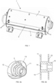
- Figure 1 shows an example of a large engine exhaust muffler 1 as known in the prior art, and in use today in large agricultural machines such as combine harvesters.
- the muffler 1 has a tubular shape having a length of about 1.2 m and an outer shell having straight side walls 2 and curved upper and lower sections 3. Inside the muffler is an exhaust trajectory that may be in accordance with any known design.
- a pair of sensor ports 4 is provided near the inlet and another pair of sensor ports 4 is provided near the outlet of the muffler 1.
- Figure 2a shows a detailed image of either one of these sensor ports 4, with a sensor 5 mounted therein.
- Figure 2b shows a section view in the vertical symmetry plane of the port 4, but without the sensor.
- the images in Figure 2a and 2b are included in order to illustrate the problems highlighted in the introductory paragraphs, and which are related to the fact that the muffler 1 comprises a double outer shell, as best visible in Figure 2b .
- the shell comprises an inner wall 10 and the outer wall 11.
- thermal insulation material (not shown) is present in the space between these walls 10 and 11.
- the sensor port 4 comprises a boss 12 that is fixed, preferably welded inside an opening in the inner wall 10 of the shell.
- the boss 12 comprises a central opening 14, preferably a threaded opening, into which the sensor 5 can be screwed tight.
- the outer wall 11 comprises an opening 13 around the boss 12 and the sensor 5 that is considerably larger than the cross-section of the boss 12, in order to allow a movement of the inner and outer walls 10 and 11 relative to each other as a consequence of the temperature difference between the two walls, without damaging the sensor 5.
- These openings 13 are present around all the sensor ports 4 and represent access locations for dirt, dust or other debris entering the area between the walls 10 and 11.
- a sealing assembly as described hereafter.
- First an embodiment of the sealing assembly is described that is designed to cover a 2-sensor port arrangement similar to the pairs of sensor ports 4 shown in Figure 1 .
- the invention is however not limited to this particular arrangement, and alternative embodiments will be described further in this specification.
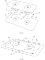
- Figure 3a shows the components of the sealing assembly before these components are assembled together.
- the assembly comprises an inner cover plate 20, an outer cover plate 21 and two washer-type elements 22.
- the term 'washer-type element' is used in the appended claims in order to distinguish these elements from what is technically understood to be a 'washer', i.e. a ring-shaped element used for example for securing bolts.
- a 'washer' i.e. a ring-shaped element used for example for securing bolts.
- the term 'washer' will nevertheless be used in the detailed description, when referring to the 'washer-type elements' 22.
- the terms 'inner plate' and 'outer plate' refer to the position of the cover plates relative to the muffler when the assembly is mounted thereon : the inner plate 20 is closer to the muffler than the outer plate 21.
- Both cover plates 20 and 21 are formed of thin steel, preferably stainless steel, which may be as thin as 0.3 mm. It is preferred to use thin plate material which can be easily adapted to the curvature of a muffler and/or to a tilted position of the sensor, which may be required for certain types of sensors. A thicker plate material is however not excluded from the scope of the invention, and the invention is not limited to any particular thickness of the plate material used for the various components of the sealing assembly.
- the inner plate 20 is smaller than the outer plate 21 and placed inside the outer circumference of the outer plate, but this is not a requirement. Both plates may have the same outer dimensions or the inner plate 20 could be larger than the outer plate 21, even though it is preferable that only the outer plate 21 is visible when the assembly is mounted on the muffler.
- the plates 20 and 21 are each provided with a pair of openings, labelled 23 for the inner plate 20 and 24 for the outer plate 21, and placed relative to each other at a distance corresponding to the distance between two sensor ports onto which the assembly is to be mounted.
- the openings 23 and 24 in the inner and outer plates have the same shape and size, so that they can be aligned to each other, forming common openings in the assembly of the plates 20 and 21, when these plates are mounted together.
- the washers 22 each comprise a planar portion 25 provided with a central aperture 26 and a tube portion 27 protruding from the edge of the central aperture 26.
- the washers 22 are equally preferably formed of thin stainless steel plate material, preferably having the same thickness as the plates 20 and 21.
- the planar portions 25 of the washers 22 are inserted between the inner and outer plates 20 and 21, with the tube portions 27 protruding through the openings 23 of the inner plate 20.
- the inner and outer plates 20 and 21 are attached to each other by a number of spot welds 30 along the circumference of the inner plate 20, as shown in Figure 3b .
- This may also be a continuous weld or any other suitable attachment means.
- the plates 20 and 21 are attached only along the edge of the smaller of the two plates, or along their common edge, when the two plates have the same outer dimensions. In any case, the plates 20 and 21 are not attached to each other across the entirety of their overlapping surfaces.
- the plates 20 and 21 are not attached to each other, enabling the washers 22 to shift laterally relative to the plates, i.e. in a direction parallel to the plates.
- This is enabled also by the fact that the cross section of the outer surface of the tube portion 27 is considerably smaller than the area of the opening 23 in the inner plate 20, through which opening 23 the tube portion 27 is protruding, i.e. there is a considerable gap between the tube portion 27 and the edge of the opening 23.
- the overlapping openings 23 and 24 are the same in size and in shape in this embodiment and are aligned to each other so that the common opening formed by two aligned openings 23 and 24 in the assembly of the plates 20 and 21 has the same shape and dimensions as the openings themselves. It is however also possible to apply an opening 24 in the outer plate 21 that is larger or smaller than the opening 23 in the inner plate 20 with the openings placed one inside the other, or the openings in the outer and inner plates could partially overlap, so that the common opening is defined by the intersection between the overlapping openings.
- the common opening is however subjected to conditions related to the dimensions of the boss and/or the sensor, as described hereafter.
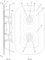
- Figure 4a shows the sealing assembly 15 of Figure 3b , before being mounted on a pair of sensor ports 4, each provided with a boss 12 of the same dimensions.
- the outer wall 11 is here provided with one large opening 13 that surrounds the two adjacent sensor ports 4.
- the tube portions 27 of the assembly are dimensioned in correspondence with the bosses 12, in such a manner that the tube portions 27 can be closely fitted onto said bosses 12, as illustrated in Figures 5a and 5b .
- the assembly is mounted onto the sensor ports 4, by placing the tube portions 27 around the bosses 12 until the outer plate 21 contacts the outer wall 11 of the muffler shell.
- the outer plate 21 is larger than the opening 13 and fully overlaps this opening.
- the opening 13, the inner plate 20 and the planar portions 25 of the washers 22 are shown in dotted lines in the frontal view of the mounted assembly in Figure 5b .
- the inner plate 20 is smaller than the opening 13 and is positioned inside this opening, but this is not a requirement of the invention (see further).
- the outer plate 21 can be attached to the outer wall 11 by roll spot seam welding or by any other suitable attachment means.
- the tube portions 27 are fitted closely around the bosses 12 so that the assembly effectively closes off the gap between the bosses 12 and the edge of the large opening 13. Nevertheless, the 'close fit' of the tube portions 27 still allows a movement of the bosses 12 relative to the tube portions 27 in a direction perpendicular to the plates 20 and 21, i.e. in a radial direction of the muffler. Radial displacements of the bosses 12 relative to the outer wall 11 are thereby allowed without subjecting the sealing assembly to stress.
- lateral displacements of the bosses 12 relative to the outer wall 11 are allowed without any danger to the sealing function of the assembly because of the close fit of the tube portions 27 around the bosses 12 and the fact that the washers 22 are moveable relative to the plates 20 and 21 in any direction parallel to these plates.
- Any lateral movement of the bosses 12 relative to the outer wall 11 is followed by the washers 22, i.e. the washers 22 move along with the bosses 12 by shifting relative to the plates 20 and 21, so that the planar portion 25 of the washers 22 continues to close off the gap between the tube portion 27 and the opening 23 in the inner plate 20, as well as the gap between the boss (and a sensor mounted thereon) and the opening 24 in the outer plate 21.
- planar portions 25 are large enough so that the gap between the bosses 12 and the opening 13 in the outer wall 11 is closed off by said planar portions 25 and by the plates 20 and 21, regardless of the position of the boss 12 relative to the outer wall 11.
- the sealing function as described above implies that the common opening defined by openings 23 and 24 is sufficiently large compared to the cross section of the bosses 12 and the tubular portions 27, and possibly of the sensors mounted onto the bosses 12, so that the bosses 12 and the tubular portions 27 as well as the sensors remain at a distance from the edge of either of the openings 23 and 24 as the bosses are displaced laterally with respect to these openings.
- This condition holds regardless of whether the openings 23 and 24 are the same size and shape and fully overlapping (as in the embodiment shown), or whether they are different in size and/or shape.
- FIG. 6 A detail (rectangle R indicated in Figure 5a ) of the mounted sealing assembly is shown in Figure 6 , indicating the various components described above.
- Figure 7 illustrates an alternative configuration, but others are possible, as is clear to the skilled person.
- the inner and outer plates 20 and 21 have the same outer dimensions.
- the inner plate 20 is now attached to the outer wall 11 of the muffler. It is seen that the outer plate 21 is slightly bent towards the inner plate 20 in the area outside the washers 22, due to the fact that both plates are formed of thin material.
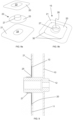
- FIGS 8a and 8b illustrate a sealing assembly according to the invention, that is suitable for sealing off a single sensor port.
- the various components described above are present here as well and are indicated in Figures 8a and 8b by the same reference numerals. The characteristics and possible alternatives described above are applicable also to this single-port embodiment.
- assemblies according to the invention may be designed for a group of any number of ports higher than 2, by adapting the dimensions and the number of the various components described above.
- Such embodiments could include higher numbers of cover plates, for example one single outer cover plate 21 and a separate inner cover plate 20 for each sensor port. If the sensor ports are sufficiently close together, a single washer 22 could be provided that is fitted to multiple bosses 12, the washer comprising a single planar portion 25, multiple apertures 26 and multiple tube portions 27 protruding from said apertures 26.
- Figure 9 illustrates an alternative configuration, according to which the sealing assembly is mounted with the tube portion 27 oriented away from the muffler, and fitted to a boss 12 that protrudes outward from the outer wall 11 of the muffler. This is possible only when the boss 12 is effectively realised in this way, i.e. protruding sufficiently beyond the outer wall 11.
- This embodiment illustrates that the tube portion 27 may protrude through the opening 23 of the inner plate 20 (as in the previous embodiment), or through the opening 24 in the outer plate 21 (as in the embodiment of Figure 9 ).
- all the components as well as the characteristics and functionalities described above are applicable also to the embodiment shown in Figure 9 .
- the inner and the outer cover plates 20 and 21 are not directly attached to each other.
- the inner plate 20 is maintained in place only by the outer plate 21.
- the outer plate 21 must be larger than the inner plate 20 and fully overlap the inner plate, and the inner plate 20 must be considerably larger than the opening 13 in the outer wall 11 of the muffler 1.
- the outer plate 21 is then fixed to the muffler's outer wall 11, for example by roll spot seam welding in a peripheral area of the outer plate 21, and thereby holds the inner plate 20 against said outer wall 11.
- the inner plate 20 is maintained essentially immobile, for example by the fact that the spot seam welds are applied close to the outer circumference of the inner plate 20, and possibly aided by high friction forces between the plates 20 and 21, to avoid that the inner plate 20 becomes displaced relative to the outer plate 21 to such a degree that the sealing function is lost.
- This process comprises : attaching the inner plate 20 to the muffler wall 11, for example by spot seam welds, placing the washer 22 over the boss 12 of the sensor port, and attaching the outer plate 21 to the muffler wall 11, for example also by spot seam welds, so that the washer 22 is mounted between the two plates 20 and 21, thereby realizing the sealing functionality as described above.
- a further alternative embodiment of the sealing assembly comprises not two plates, but a single cover plate.
- the outer plate 21 plays the role of the single cover plate, having an opening 24 that overlaps the opening 13 in the outer muffler wall 11.
- This embodiment is illustrated in Figure 10 .
- the planar portion 25 of the washer 22 is now held between the single cover plate 21 and the outer wall 11 of the muffler.
- the cover plate 21 is attached to the muffler wall for example by spot seam welds, indicated by the dotted lines 31, in a peripheral area of the plate 21. This leaves sufficient area between the plate 21 and the muffler wall 11 for the washer 22 to move relative to said muffler wall 11 and relative to the plate 21, in a direction parallel to the wall 11.
- the tube portion 27 of the washer 22 is fitted to the boss 12 in the same way as described above for the embodiments comprising two cover plates.
- the single plate embodiment is equally preferably assembled as it is being attached to the muffler, by the steps of: fitting the washer 22 over the boss 12, and placing the planar portion 25 of the washer against the outer wall 11 of the muffler, followed by placing the single cover plate 21 over the washer 22 and attaching the plate 21 to the outer wall 11, for example by spot seam welds 31.
- the latter embodiment can also be applied to seal off a group of closely spaced sensor ports 4, by providing a single cover plate 21 and a separate washer 22 for each sensor port, when each sensor port is provided with its own opening 13 around the boss 12.
- a single cover plate 21 and one or more washers 22 that comprise a single planar portion 25 having multiple apertures 26 with multiple tube portions 27 protruding from the apertures of the single planar portion 25.
- the outer cover plate 21 is attached to the outer wall 11 of the muffler. In most embodiments said outer cover plate 21 is attached directly to said wall.
- the outer plate 21 is smaller than the inner plate 20, the outer plate is directly attached to the inner plate 20, said inner plate being directly attached to the muffler wall. So in this case the outer plate 21 is attached to the muffler wall 11 via the inner plate, which also represents an embodiment of the outer plate being 'attached to the outer wall of the muffler'.
- the planar portion 25 of the washer 22 is mounted between the outer cover plate 21 and the muffler.
- the sealing assembly comprises an inner plate as well, the planar portion 25 is mounted between the plates 20 and 21, and is thereby still 'between the outer plate and the muffler'.
Landscapes
- Engineering & Computer Science (AREA)
- Chemical & Material Sciences (AREA)
- General Engineering & Computer Science (AREA)
- Mechanical Engineering (AREA)
- Combustion & Propulsion (AREA)
- Analytical Chemistry (AREA)
- Chemical Kinetics & Catalysis (AREA)
- Exhaust Silencers (AREA)
Description
- The present invention is related to acoustic mufflers, primarily to engine exhaust mufflers, in particular to the mounting of sensors on a double-walled muffler. Such sensors may be used to measure operational parameters of the muffler, such as NOx concentration, NH3 concentration, temperature, pressure, etc.
- It is well-known to design an engine exhaust muffler in the form of an elongated cylinder with a double-walled shell formed of an inner wall and an outer wall, preferably with a thermal insulation material between the two, in order to limit the temperature of the muffler's outer surface and/or to raise the temperature inside for optimizing the exhaust gas conversion process. When a sensor is mounted on the muffler, this sensor is mounted in a sensor port comprising a boss that is usually welded inside an opening provided in the inner wall. The boss may be provided with an inner thread into which the sensor casing can be screwed so that the sensing portion of the sensor is inserted in the inner volume of the muffler. On the opposite side, the sensor must be accessible in order to connect it to a measurement unit. To this aim, an opening is provided through the outer wall.
- Due to the gap between the walls and even more so when the gap is filled with insulation material, an important temperature difference appears between the inner and outer walls of the muffler, once the muffler reaches an operational temperature. As a consequence of this, the inner and outer wall undergo important dimensional shifts with respect to each other, both in the axial direction and in the radial direction of the muffler. The opening provided in the outer wall therefore needs to be considerably larger than the area required for accessing the sensor, so that the relative shift of the walls can take place without damaging the sensor or its connection towards the measurement unit.
- Especially in large mufflers, such as the ones used in large agricultural machines, for example combine or forage harvesters, the relative shifts between the inner and outer walls can be in the order of several millimetres, requiring therefore a large gap between the sensor and the outer wall, i.e. a large opening in the outer wall surrounding the boss of the sensor port.
- This opening gives access to dirt or debris, leading to a fire hazard as dirt or dust particles come into contact with the high temperature of the muffler's inner wall. This problem is particularly acute in working environments containing high amounts of dirt or debris particles, such as in an agricultural context.
-
US 2015/059457 A1 describes an aftertreatment module including a conduit defining a flow path, with a shield arranged at least partway around the conduit and spaced therefrom, and with a boss provided on the conduit. A sensor is disposed within the boss so as to extend at least partway into the flow path and a spacer is arranged around the boss. - The invention is related to a muffler in which the above-described problems have been resolved. The present invention is related to a sealing assembly for a sensor port of a double-walled muffler, and to a muffler provided with such a sealing assembly, as disclosed in the appended claims. The sealing assembly comprises at least an outer plate and a washer-type element, preferably all made of thin steel plate material, for example stainless steel plate of about 0.3 mm thickness. According to an embodiment, the assembly further comprises an inner plate. In that case, the plates are assembled one on top of the other and have overlapping openings. The washer-type element has a planar portion provided with an aperture, and a tube portion protruding from the edge of the aperture. The planar portion is caught between the plates or between the single outer plate and the muffler. The assembly is configured in a manner that allows a lateral movement of the washer-type element relative to the plate or plates. The assembly is mounted on a sensor port that is provided with a boss fixed to the inner wall of the double muffler wall, and with an opening in the outer wall surrounding the boss. The tube portion is fitted over the boss and the single plate or the assembly of the plates is fixed to the outer wall of the muffler, thereby closing off the sensor port from the exterior of the muffler. Any radial or lateral movement of the boss relative to the outer wall is able to take place without losing the sealing function, due to the lateral freedom of movement of the washer-type element relative to the plate or plates, and due to the fact that the boss is able to move relative to the tube portion in a direction perpendicular to the plate or plates, i.e. in a radial direction of the muffler.
- The sealing assembly thereby effectively closes off the sensor port, while still allowing any movement of the boss relative to the outer wall, as a consequence of the temperature difference between the inner and outer wall.
-
-
Figure 1 is an image of a prior art muffler that is suitable for use in an agricultural machine such as a combine harvester. -
Figure 2a is a detail of a sensor port in the muffler shown inFigure 1. Figure 2b is a section view of the sensor port. -
Figure 3a shows the components of a sealing assembly applicable in a muffler according to the invention. -
Figure 3b is an image of the sealing assembly in the assembled state. -
Figure 4a is a section view of the sealing assembly and of two sensor ports, prior to mounting the assembly onto these ports. -
Figure 4b is a frontal view of the two sensor ports. -
Figure 5a is a section view of the sealing assembly and the sensor ports, with the assembly mounted thereon. -
Figure 5b is a frontal view of the sensor ports with the assembly mounted thereon. -
Figure 6 is a detail of the mounted sealing assembly shown inFigure 5b , which allows a more detailed view of the positions of the various constituent components. -
Figure 7 is a detail of an alternative configuration in terms of the dimensions of the inner and outer plate of the sealing assembly and of the openings provided therein. -
Figures 8a and 8b are views prior and after assembling the components, of a sealing assembly according to the invention, configured to close off a single sensor port. -
Figure 9 illustrates an embodiment wherein the tube portion of the movable washer of the sealing assembly is oriented away from the muffler's outer wall. -
Figure 10 illustrates an embodiment wherein the sealing assembly comprises a single cover plate. - Preferred embodiments will now be described with reference to the drawings. The detailed description is not limiting the scope of the invention, which is defined only by the appended claims.
-
Figure 1 shows an example of a largeengine exhaust muffler 1 as known in the prior art, and in use today in large agricultural machines such as combine harvesters. Themuffler 1 has a tubular shape having a length of about 1.2 m and an outer shell havingstraight side walls 2 and curved upper andlower sections 3. Inside the muffler is an exhaust trajectory that may be in accordance with any known design. - A pair of
sensor ports 4 is provided near the inlet and another pair ofsensor ports 4 is provided near the outlet of themuffler 1.Figure 2a shows a detailed image of either one of thesesensor ports 4, with asensor 5 mounted therein.Figure 2b shows a section view in the vertical symmetry plane of theport 4, but without the sensor. - The images in
Figure 2a and 2b are included in order to illustrate the problems highlighted in the introductory paragraphs, and which are related to the fact that themuffler 1 comprises a double outer shell, as best visible inFigure 2b . The shell comprises aninner wall 10 and theouter wall 11. Preferably, thermal insulation material (not shown) is present in the space between thesewalls sensor port 4 comprises aboss 12 that is fixed, preferably welded inside an opening in theinner wall 10 of the shell. Theboss 12 comprises acentral opening 14, preferably a threaded opening, into which thesensor 5 can be screwed tight. - As seen in the drawings, the
outer wall 11 comprises anopening 13 around theboss 12 and thesensor 5 that is considerably larger than the cross-section of theboss 12, in order to allow a movement of the inner andouter walls sensor 5. Theseopenings 13 are present around all thesensor ports 4 and represent access locations for dirt, dust or other debris entering the area between thewalls - In a
muffler 1 according to the present invention,such openings 13 are closed off from the environment by a sealing assembly as described hereafter. First an embodiment of the sealing assembly is described that is designed to cover a 2-sensor port arrangement similar to the pairs ofsensor ports 4 shown inFigure 1 . The invention is however not limited to this particular arrangement, and alternative embodiments will be described further in this specification. -
Figure 3a shows the components of the sealing assembly before these components are assembled together. The assembly comprises aninner cover plate 20, anouter cover plate 21 and two washer-type elements 22. The term 'washer-type element' is used in the appended claims in order to distinguish these elements from what is technically understood to be a 'washer', i.e. a ring-shaped element used for example for securing bolts. For the sake of brevity, the term 'washer' will nevertheless be used in the detailed description, when referring to the 'washer-type elements' 22. - The terms 'inner plate' and 'outer plate' refer to the position of the cover plates relative to the muffler when the assembly is mounted thereon : the
inner plate 20 is closer to the muffler than theouter plate 21. - Both cover
plates - In the embodiment shown, the
inner plate 20 is smaller than theouter plate 21 and placed inside the outer circumference of the outer plate, but this is not a requirement. Both plates may have the same outer dimensions or theinner plate 20 could be larger than theouter plate 21, even though it is preferable that only theouter plate 21 is visible when the assembly is mounted on the muffler. - The
plates inner plate outer plate 21, and placed relative to each other at a distance corresponding to the distance between two sensor ports onto which the assembly is to be mounted. In the embodiment shown, theopenings plates - The
washers 22 each comprise aplanar portion 25 provided with acentral aperture 26 and atube portion 27 protruding from the edge of thecentral aperture 26. Thewashers 22 are equally preferably formed of thin stainless steel plate material, preferably having the same thickness as theplates - When these various components are assembled together, as seen in
Figure 3b , to obtain the sealingassembly 15, theplanar portions 25 of thewashers 22 are inserted between the inner andouter plates tube portions 27 protruding through theopenings 23 of theinner plate 20. The inner andouter plates spot welds 30 along the circumference of theinner plate 20, as shown inFigure 3b . This may also be a continuous weld or any other suitable attachment means. Preferably, theplates plates openings plates washers 22 to shift laterally relative to the plates, i.e. in a direction parallel to the plates. This is enabled also by the fact that the cross section of the outer surface of thetube portion 27 is considerably smaller than the area of theopening 23 in theinner plate 20, through whichopening 23 thetube portion 27 is protruding, i.e. there is a considerable gap between thetube portion 27 and the edge of theopening 23. - As noted above, the overlapping
openings openings plates opening 24 in theouter plate 21 that is larger or smaller than theopening 23 in theinner plate 20 with the openings placed one inside the other, or the openings in the outer and inner plates could partially overlap, so that the common opening is defined by the intersection between the overlapping openings. The common opening is however subjected to conditions related to the dimensions of the boss and/or the sensor, as described hereafter. -
Figure 4a shows the sealingassembly 15 ofFigure 3b , before being mounted on a pair ofsensor ports 4, each provided with aboss 12 of the same dimensions. As best seen in the frontal view inFigure 4b , theouter wall 11 is here provided with onelarge opening 13 that surrounds the twoadjacent sensor ports 4. Thetube portions 27 of the assembly are dimensioned in correspondence with thebosses 12, in such a manner that thetube portions 27 can be closely fitted onto saidbosses 12, as illustrated inFigures 5a and 5b . The assembly is mounted onto thesensor ports 4, by placing thetube portions 27 around thebosses 12 until theouter plate 21 contacts theouter wall 11 of the muffler shell. Theouter plate 21 is larger than theopening 13 and fully overlaps this opening. Theopening 13, theinner plate 20 and theplanar portions 25 of thewashers 22 are shown in dotted lines in the frontal view of the mounted assembly inFigure 5b . In this particular embodiment, theinner plate 20 is smaller than theopening 13 and is positioned inside this opening, but this is not a requirement of the invention (see further). Theouter plate 21 can be attached to theouter wall 11 by roll spot seam welding or by any other suitable attachment means. - The
tube portions 27 are fitted closely around thebosses 12 so that the assembly effectively closes off the gap between thebosses 12 and the edge of thelarge opening 13. Nevertheless, the 'close fit' of thetube portions 27 still allows a movement of thebosses 12 relative to thetube portions 27 in a direction perpendicular to theplates bosses 12 relative to theouter wall 11 are thereby allowed without subjecting the sealing assembly to stress. Also, lateral displacements of thebosses 12 relative to theouter wall 11 are allowed without any danger to the sealing function of the assembly because of the close fit of thetube portions 27 around thebosses 12 and the fact that thewashers 22 are moveable relative to theplates bosses 12 relative to theouter wall 11 is followed by thewashers 22, i.e. thewashers 22 move along with thebosses 12 by shifting relative to theplates planar portion 25 of thewashers 22 continues to close off the gap between thetube portion 27 and theopening 23 in theinner plate 20, as well as the gap between the boss (and a sensor mounted thereon) and theopening 24 in theouter plate 21. This requires of course that the dimensions of theplanar portions 25 are large enough so that the gap between thebosses 12 and theopening 13 in theouter wall 11 is closed off by saidplanar portions 25 and by theplates boss 12 relative to theouter wall 11. - The sealing function as described above implies that the common opening defined by
openings bosses 12 and thetubular portions 27, and possibly of the sensors mounted onto thebosses 12, so that thebosses 12 and thetubular portions 27 as well as the sensors remain at a distance from the edge of either of theopenings openings - A detail (rectangle R indicated in
Figure 5a ) of the mounted sealing assembly is shown inFigure 6 , indicating the various components described above. As stated, alternative configurations are possible, for instance in terms of the dimensions of the inner andouter plates outer wall 11 of the muffler.Figure 7 illustrates an alternative configuration, but others are possible, as is clear to the skilled person. In the embodiment ofFigure 7 , the inner andouter plates inner plate 20 is now attached to theouter wall 11 of the muffler. It is seen that theouter plate 21 is slightly bent towards theinner plate 20 in the area outside thewashers 22, due to the fact that both plates are formed of thin material. This however does not obstruct the lateral movement of thewashers 22 relative to the plates, which is ensured preferably by welding theplates spot welds 30, as illustrated inFigure 7 . Another difference with the first embodiment, illustrated inFigure 7 , and applicable independently of changes in the relative outer dimensions of the plates, is that theopening 23 in theinner plate 20 is larger than theopening 24 in theouter plate 21. Theopening 24 therefore defines the common opening obtained by the overlappingopenings -
Figures 8a and 8b illustrate a sealing assembly according to the invention, that is suitable for sealing off a single sensor port. The various components described above are present here as well and are indicated inFigures 8a and 8b by the same reference numerals. The characteristics and possible alternatives described above are applicable also to this single-port embodiment. Likewise, assemblies according to the invention may be designed for a group of any number of ports higher than 2, by adapting the dimensions and the number of the various components described above. Such embodiments could include higher numbers of cover plates, for example one singleouter cover plate 21 and a separateinner cover plate 20 for each sensor port. If the sensor ports are sufficiently close together, asingle washer 22 could be provided that is fitted tomultiple bosses 12, the washer comprising a singleplanar portion 25,multiple apertures 26 andmultiple tube portions 27 protruding from saidapertures 26. -
Figure 9 illustrates an alternative configuration, according to which the sealing assembly is mounted with thetube portion 27 oriented away from the muffler, and fitted to aboss 12 that protrudes outward from theouter wall 11 of the muffler. This is possible only when theboss 12 is effectively realised in this way, i.e. protruding sufficiently beyond theouter wall 11. This embodiment illustrates that thetube portion 27 may protrude through theopening 23 of the inner plate 20 (as in the previous embodiment), or through theopening 24 in the outer plate 21 (as in the embodiment ofFigure 9 ). Apart from this difference, all the components as well as the characteristics and functionalities described above are applicable also to the embodiment shown inFigure 9 . - According to alternative embodiments of the invention, the inner and the
outer cover plates inner plate 20 is maintained in place only by theouter plate 21. In this case, theouter plate 21 must be larger than theinner plate 20 and fully overlap the inner plate, and theinner plate 20 must be considerably larger than theopening 13 in theouter wall 11 of themuffler 1. Theouter plate 21 is then fixed to the muffler'souter wall 11, for example by roll spot seam welding in a peripheral area of theouter plate 21, and thereby holds theinner plate 20 against saidouter wall 11. Preferably theinner plate 20 is maintained essentially immobile, for example by the fact that the spot seam welds are applied close to the outer circumference of theinner plate 20, and possibly aided by high friction forces between theplates inner plate 20 becomes displaced relative to theouter plate 21 to such a degree that the sealing function is lost. - When the
inner plate 20 is smaller than theouter plate 21 and placed fully within the circumference of theouter plate 21, while being larger than theopening 13 in theouter muffler wall 11, it is also possible to attach both the inner and the outer plate to themuffler wall 11, without attaching them directly to each other. This last embodiment of the sealing assembly cannot be assembled fully before attaching it to the muffler, but it is assembled in the course of attaching it to the muffler. This process comprises : attaching theinner plate 20 to themuffler wall 11, for example by spot seam welds, placing thewasher 22 over theboss 12 of the sensor port, and attaching theouter plate 21 to themuffler wall 11, for example also by spot seam welds, so that thewasher 22 is mounted between the twoplates - A further alternative embodiment of the sealing assembly comprises not two plates, but a single cover plate. In this case, the
outer plate 21 plays the role of the single cover plate, having anopening 24 that overlaps theopening 13 in theouter muffler wall 11. This embodiment is illustrated inFigure 10 . Theplanar portion 25 of thewasher 22 is now held between thesingle cover plate 21 and theouter wall 11 of the muffler. Thecover plate 21 is attached to the muffler wall for example by spot seam welds, indicated by the dottedlines 31, in a peripheral area of theplate 21. This leaves sufficient area between theplate 21 and themuffler wall 11 for thewasher 22 to move relative to saidmuffler wall 11 and relative to theplate 21, in a direction parallel to thewall 11. Thetube portion 27 of thewasher 22 is fitted to theboss 12 in the same way as described above for the embodiments comprising two cover plates. The single plate embodiment is equally preferably assembled as it is being attached to the muffler, by the steps of: fitting thewasher 22 over theboss 12, and placing theplanar portion 25 of the washer against theouter wall 11 of the muffler, followed by placing thesingle cover plate 21 over thewasher 22 and attaching theplate 21 to theouter wall 11, for example by spot seam welds 31. - The latter embodiment can also be applied to seal off a group of closely spaced
sensor ports 4, by providing asingle cover plate 21 and aseparate washer 22 for each sensor port, when each sensor port is provided with itsown opening 13 around theboss 12. When oneopening 13 surroundsmultiple bosses 12, it would be possible to provide asingle cover plate 21 and one ormore washers 22 that comprise a singleplanar portion 25 havingmultiple apertures 26 withmultiple tube portions 27 protruding from the apertures of the singleplanar portion 25. - According to any embodiment of the sealing assembly (single plate or inner/outer plate), the
outer cover plate 21 is attached to theouter wall 11 of the muffler. In most embodiments saidouter cover plate 21 is attached directly to said wall. When theouter plate 21 is smaller than theinner plate 20, the outer plate is directly attached to theinner plate 20, said inner plate being directly attached to the muffler wall. So in this case theouter plate 21 is attached to themuffler wall 11 via the inner plate, which also represents an embodiment of the outer plate being 'attached to the outer wall of the muffler'. - Also according to any embodiment, the
planar portion 25 of thewasher 22 is mounted between theouter cover plate 21 and the muffler. When the sealing assembly comprises an inner plate as well, theplanar portion 25 is mounted between theplates
Claims (11)
- A muffler (1) comprising an inner wall (10) and an outer wall (11), and comprising at least one sensor port (4), the sensor port comprising a boss (12) suitable for receiving a sensor (5), wherein the boss is fixed to the inner wall (10), and wherein the outer wall (11) is provided with an opening (13) around the boss (12),characterised in that the muffler further comprises a sealing assembly (15) comprising :- one or more cover plates (20,21) comprising at least an outer cover plate (21) attached to the outer wall (11) and provided with an opening (24) that overlaps the opening (13) around the boss (12) and- at least one washer-type element (22) that comprises a planar portion (25) provided with an aperture (26) and a tube portion (27) protruding from the edge of the aperture (26),and wherein :- the planar portion (25) of the washer-type element (22) is mounted between the muffler (1) and the outer cover plate (21), in a way that allows movement of the washer-type element (22) relative to the outer cover plate (21) in a direction parallel to said cover plate,- the tube portion (27) of the washer-type element protrudes through the opening (24) of the outer cover plate (21) or through the opening (13) in the outer wall (11) of the muffler,- the tube portion (27) of the washer-type element (22) is fitted around the boss (12) in such a way that :∘ the boss (12) is movable relative to the tube portion (27) in a direction perpendicular to the planar portion (25) of the washer-type element (22),∘ when the boss (12) moves in a direction parallel to the outer wall (11), and relative to said outer wall (11), the tube portion (27) and thereby the washer-type element (22) as a whole undergoes the same movement, relative to the outer wall (11) and relative to the cover plate (21),- the dimensions of the planar portion (25) of the washer-type element (22) are such that the gap between the boss (12) and the opening (13) in the outer wall (11) is closed off by said planar portion (25) and by the one or more cover plates (20,21), regardless of the position of the boss (12) relative to the outer wall (11).
- The muffler according to claim 1, wherein the sealing assembly comprises only said outer cover plate (21) and wherein the washer-type element (22) is held against the outer muffler wall (11) by the outer cover plate (21).
- The muffler (1) according to claim 2, comprising two or more sensor ports (4) placed in a group and each comprising a boss (12), wherein the outer wall (11) of the muffler is provided with a separate opening (13) for each boss, or at least one opening (13) placed around multiple bosses (12), wherein the sealing assembly (15) comprises :- a single outer plate (21), provided with multiple openings (23,24) corresponding to the number of ports (4),- multiple washer-type elements (22), the number of said elements corresponding to the number of ports (4), or one or more washer-type elements comprising a single planar portion (25) and multiple apertures (26) and tube portions (27).
- The muffler according to claim 1, wherein the sealing assembly comprises said outer cover plate (21) and an inner cover plate (20) and wherein :- the plates (20,21) are assembled one on top of the other and comprise openings (23,24) that mutually overlap,- the plates (20,21) have either a common outer edge or one plate is smaller than the other and placed inside the outer edge of the other,- the planar portion (25) of the washer-type element is mounted between the two plates (20,21) with the tube portion (27) protruding :∘ either through the opening (23) of the inner plate (20) and the opening (13) in the outer wall (11) of the muffler, or∘ through the opening (24) of the outer plate (21),- the plates (20,21) are arranged relative to each other in a way that allows movement of the washer-type element (22) relative to the plates in a direction parallel to the plates, wherein said movement is also enabled by the dimensions of the overlapping openings (23,24),- the sealing assembly (15) is attached to the outer wall (11) of the muffler (1) with the outer plate (21) facing away from the muffler, wherein depending on the relative dimensions of the plates one of the following cases applies :∘ only the outer plate (21) is directly attached to the outside wall (11) of the muffler, or∘ only the inner plate (20) is directly attached to the outside wall (11) of the muffler and the outer plate (21) is directly attached to the inner plate (20), or∘ both the inner plate (20) and the outer plate (21) are directly attached to the outside wall (11) of the muffler.
- The muffler (1) according to claim 4, wherein the mutually overlapping openings (23,24) of the plates (20,21) have the same size and shape and are aligned to each other.
- The muffler (1) according to claim 4 or 5, wherein the inner plate (20) and the outer plate (21) are attached to each other.
- The muffler (1) according to claim 6, wherein the inner plate (20) and the outer plate (21) are attached to each other only along their common outer edge or only along the edge of the smaller of the two plates.
- The muffler (1) according to any one of claims 4 to 7, wherein the inner plate (20) is situated inside the circumference of the opening (13) in the outer wall (11) of the muffler (1) and wherein only the outer plate (21) is directly attached to the outer wall (11) of the muffler.
- The muffler (1) according to any one of claims 4 to 7, wherein the inner plate (20) is larger than and fully overlaps the opening (13) in the outer wall (11).
- The muffler (1) according to any one of claims 4 to 9, comprising two or more sensor ports (4) placed in a group and each comprising a boss (12), wherein the outer wall (11) of the muffler is provided with a separate opening (13) for each boss, or at least one opening (13) placed around multiple bosses (12), and wherein the sealing assembly (15) comprises:- a single inner plate (20) and a single outer plate (21), each provided with multiple openings (23,24) corresponding to the number of ports (4), or a single outer plate (21) and multiple inner plates (20),- multiple washer-type elements (22), the number of said elements corresponding to the number of ports (4) or one or more washer-type elements (22) comprising a single planar portion (25), multiple apertures (26) and multiple tube portions (27).
- The muffler (1) according to any one of the preceding claims, wherein the one or more cover plates (20,21) and the washer-type element (22) are formed of thin plate material, preferably of plate material having a thickness lower than 1 mm.
Priority Applications (4)
| Application Number | Priority Date | Filing Date | Title |
|---|---|---|---|
| EP21183001.3A EP4112891B1 (en) | 2021-06-30 | 2021-06-30 | A muffler comprising one or more sensor ports |
| BR102022012822-7A BR102022012822A2 (en) | 2021-06-30 | 2022-06-27 | SILENCER AND SEALING ASSEMBLY |
| CN202210755228.6A CN115539184B (en) | 2021-06-30 | 2022-06-29 | Muffler including one or more sensor ports |
| US17/855,783 US12065952B2 (en) | 2021-06-30 | 2022-06-30 | Muffler comprising one or more sensor ports |
Applications Claiming Priority (1)
| Application Number | Priority Date | Filing Date | Title |
|---|---|---|---|
| EP21183001.3A EP4112891B1 (en) | 2021-06-30 | 2021-06-30 | A muffler comprising one or more sensor ports |
Publications (2)
| Publication Number | Publication Date |
|---|---|
| EP4112891A1 EP4112891A1 (en) | 2023-01-04 |
| EP4112891B1 true EP4112891B1 (en) | 2025-03-05 |
Family
ID=76744620
Family Applications (1)
| Application Number | Title | Priority Date | Filing Date |
|---|---|---|---|
| EP21183001.3A Active EP4112891B1 (en) | 2021-06-30 | 2021-06-30 | A muffler comprising one or more sensor ports |
Country Status (4)
| Country | Link |
|---|---|
| US (1) | US12065952B2 (en) |
| EP (1) | EP4112891B1 (en) |
| CN (1) | CN115539184B (en) |
| BR (1) | BR102022012822A2 (en) |
Family Cites Families (32)
| Publication number | Priority date | Publication date | Assignee | Title |
|---|---|---|---|---|
| DE4100935A1 (en) | 1991-01-15 | 1992-07-16 | Bayerische Motoren Werke Ag | Double skinned catalytic converter housing with insulation - has one skin layer folded over insulation at lambda probe insertion point |
| JP3355807B2 (en) * | 1994-09-19 | 2002-12-09 | 日産自動車株式会社 | Catalytic converter device with oxygen sensor for internal combustion engine |
| JPH08246863A (en) | 1995-01-13 | 1996-09-24 | Toyota Motor Corp | Exhaust pipe of internal combustion engine |
| JP3329358B2 (en) | 1995-04-24 | 2002-09-30 | カルソニックカンセイ株式会社 | Exhaust gas purification equipment |
| JP4604267B2 (en) * | 2001-03-23 | 2011-01-05 | 株式会社三五 | Exhaust pipe |
| US6996976B2 (en) | 2002-04-03 | 2006-02-14 | Cleaire Advanced Emmision Controls | Apparatus and method for mounting a device to a pipe |
| JP2007023850A (en) | 2005-07-14 | 2007-02-01 | Calsonic Kansei Corp | Boss part structure for sensor attachment |
| US8110154B2 (en) * | 2006-02-01 | 2012-02-07 | Katcon Global S.A. | Exhaust treatment device with sensor and method of making |
| DE102008017625B4 (en) | 2008-04-04 | 2013-05-16 | Tenneco Gmbh | Section for an exhaust system of an internal combustion engine and method for its production |
| JP2011052605A (en) | 2009-09-02 | 2011-03-17 | Yamaha Motor Co Ltd | Exhaust system, saddle type vehicle having the same, and method of manufacturing and mounting exhaust pipe |
| WO2011118527A1 (en) * | 2010-03-23 | 2011-09-29 | ヤンマー株式会社 | Exhaust gas purification device |
| DE102010060071A1 (en) | 2010-10-20 | 2012-05-10 | Dr. Ing. H.C. F. Porsche Aktiengesellschaft | Exhaust system component for internal combustion engine of vehicle, comprises exhaust gas-conducting unit and insulation for exhaust gas-conducting unit, where sensor unit is mounted in area of insulation in exhaust gas-conducting unit |
| JP2012107591A (en) * | 2010-11-18 | 2012-06-07 | Suzuki Motor Corp | Structure for mounting component to exhaust pipe |
| JP5671366B2 (en) | 2011-02-19 | 2015-02-18 | 本田技研工業株式会社 | Saddle riding |
| US9217355B2 (en) * | 2011-12-12 | 2015-12-22 | Caterpillar Inc. | Sensor mounting arrangement |
| GB201207201D0 (en) * | 2012-04-24 | 2012-06-06 | Perkins Engines Co Ltd | Emissions cleaning module for a diesel engine |
| WO2014084959A1 (en) | 2012-11-30 | 2014-06-05 | Cnh America Llc | Exhaust system for an off-road vehicle |
| DE102013222594A1 (en) * | 2013-03-12 | 2014-09-18 | Robert Bosch Gmbh | Special sealing geometry for exhaust gas sensors to create a high level of tightness |
| US9057315B2 (en) | 2013-07-08 | 2015-06-16 | Honda Motor Co., Ltd. | Oxygen sensor heat sinking boss |
| US9382832B2 (en) * | 2014-04-17 | 2016-07-05 | Honda Motor Co., Ltd. | Sensor heat shield structure for a vehicle exhaust system |
| JP6704246B2 (en) * | 2015-12-18 | 2020-06-03 | 川崎重工業株式会社 | Saddle type vehicle |
| US10895190B2 (en) * | 2016-03-24 | 2021-01-19 | Faurecia Emissions Control Technologies, Usa, Llc | Insulated heat shield for vehicle exhaust system |
| US10519842B2 (en) | 2016-05-17 | 2019-12-31 | Ford Global Technologies, Llc | Exhaust sensor module shield |
| JP6420803B2 (en) | 2016-09-23 | 2018-11-07 | 本田技研工業株式会社 | Exhaust gas purification catalyst heating device |
| US20180274468A1 (en) | 2017-03-24 | 2018-09-27 | GM Global Technology Operations LLC | Vehicle exhaust system |
| CN108150266B (en) | 2017-11-27 | 2020-09-15 | 北汽福田汽车股份有限公司 | Exhaust silencing system, backflow prevention method of exhaust silencing system and vehicle |
| DE102018104244A1 (en) * | 2018-02-26 | 2019-08-29 | Eberspächer Exhaust Technology GmbH & Co. KG | exhaust system |
| US10934923B2 (en) * | 2019-01-09 | 2021-03-02 | Caterpillar Inc. | Heat shield assembly for shielding a wire harness |
| BR112021016709A2 (en) | 2019-02-27 | 2021-10-13 | Tvs Motor Company Limited | UNLOAD SYSTEM AND ENGINE VEHICLE OF THE SAME |
| JP6866420B2 (en) | 2019-06-03 | 2021-04-28 | 本田技研工業株式会社 | Saddle-riding vehicle |
| US10823036B1 (en) * | 2019-06-25 | 2020-11-03 | Faurecia Emissions Control Technologies, Usa, Llc | Method and apparatus to accommodate sensors on an exhaust component |
| US11560825B2 (en) | 2019-10-17 | 2023-01-24 | Honda Motor Co., Ltd. | Muffler heat protection assembly |
-
2021
- 2021-06-30 EP EP21183001.3A patent/EP4112891B1/en active Active
-
2022
- 2022-06-27 BR BR102022012822-7A patent/BR102022012822A2/en not_active Application Discontinuation
- 2022-06-29 CN CN202210755228.6A patent/CN115539184B/en active Active
- 2022-06-30 US US17/855,783 patent/US12065952B2/en active Active
Also Published As
| Publication number | Publication date |
|---|---|
| CN115539184B (en) | 2025-08-19 |
| US12065952B2 (en) | 2024-08-20 |
| EP4112891A1 (en) | 2023-01-04 |
| CN115539184A (en) | 2022-12-30 |
| US20230003148A1 (en) | 2023-01-05 |
| BR102022012822A2 (en) | 2023-01-31 |
Similar Documents
| Publication | Publication Date | Title |
|---|---|---|
| EP2065579B1 (en) | Collecting portion structure of exhaust manifold | |
| US6155046A (en) | Heat-insulation type exhaust manifold | |
| KR101244724B1 (en) | Exhaust gas purifying device | |
| US7870777B2 (en) | Gas sensor | |
| US8328203B2 (en) | Sealing system for exhaust-gas lines | |
| US5927724A (en) | Cylinder head gasket | |
| US3940927A (en) | Internal combustion engine having a reactor for afterburning of unburned exhaust gas constituents | |
| US20160290212A1 (en) | Attachment assembly for heat-shield arrangement | |
| JP2005163623A (en) | Exhaust manifold | |
| EP2551483A1 (en) | Exhaust gas purification device | |
| US12065952B2 (en) | Muffler comprising one or more sensor ports | |
| KR20000064242A (en) | Gas sensor | |
| KR19990081953A (en) | Gas sensor | |
| US20050166584A1 (en) | Gasket and heat shield assembly for a flanged joint | |
| JPH0318611A (en) | Exhaust device for internal combustion engine | |
| US6485007B1 (en) | Diaphragm bellows device | |
| US12091998B2 (en) | Muffler | |
| CN110005506B (en) | Silencing system | |
| US11015612B2 (en) | Turbine housing | |
| JP5141647B2 (en) | Exhaust gas guide device to sensor element and engine exhaust system structure | |
| US20030006301A1 (en) | Double pipe exhaust manifold | |
| US7131433B1 (en) | Positive crankcase ventilation valve assembly | |
| US6668973B2 (en) | Transverse partition for exhaust volume | |
| JP2002285838A (en) | Exhaust pipe | |
| JP3424433B2 (en) | Dual protector structure of oxygen sensor |
Legal Events
| Date | Code | Title | Description |
|---|---|---|---|
| PUAI | Public reference made under article 153(3) epc to a published international application that has entered the european phase |
Free format text: ORIGINAL CODE: 0009012 |
|
| STAA | Information on the status of an ep patent application or granted ep patent |
Free format text: STATUS: THE APPLICATION HAS BEEN PUBLISHED |
|
| AK | Designated contracting states |
Kind code of ref document: A1 Designated state(s): AL AT BE BG CH CY CZ DE DK EE ES FI FR GB GR HR HU IE IS IT LI LT LU LV MC MK MT NL NO PL PT RO RS SE SI SK SM TR |
|
| STAA | Information on the status of an ep patent application or granted ep patent |
Free format text: STATUS: REQUEST FOR EXAMINATION WAS MADE |
|
| 17P | Request for examination filed |
Effective date: 20230704 |
|
| RBV | Designated contracting states (corrected) |
Designated state(s): AL AT BE BG CH CY CZ DE DK EE ES FI FR GB GR HR HU IE IS IT LI LT LU LV MC MK MT NL NO PL PT RO RS SE SI SK SM TR |
|
| GRAP | Despatch of communication of intention to grant a patent |
Free format text: ORIGINAL CODE: EPIDOSNIGR1 |
|
| STAA | Information on the status of an ep patent application or granted ep patent |
Free format text: STATUS: GRANT OF PATENT IS INTENDED |
|
| RIC1 | Information provided on ipc code assigned before grant |
Ipc: F01N 13/14 20100101ALI20240829BHEP Ipc: F01N 13/00 20100101ALI20240829BHEP Ipc: F01N 1/00 20060101AFI20240829BHEP |
|
| INTG | Intention to grant announced |
Effective date: 20240924 |
|
| GRAS | Grant fee paid |
Free format text: ORIGINAL CODE: EPIDOSNIGR3 |
|
| GRAA | (expected) grant |
Free format text: ORIGINAL CODE: 0009210 |
|
| STAA | Information on the status of an ep patent application or granted ep patent |
Free format text: STATUS: THE PATENT HAS BEEN GRANTED |
|
| AK | Designated contracting states |
Kind code of ref document: B1 Designated state(s): AL AT BE BG CH CY CZ DE DK EE ES FI FR GB GR HR HU IE IS IT LI LT LU LV MC MK MT NL NO PL PT RO RS SE SI SK SM TR |
|
| REG | Reference to a national code |
Ref country code: GB Ref legal event code: FG4D |
|
| REG | Reference to a national code |
Ref country code: CH Ref legal event code: EP |
|
| REG | Reference to a national code |
Ref country code: IE Ref legal event code: FG4D |
|
| REG | Reference to a national code |
Ref country code: DE Ref legal event code: R096 Ref document number: 602021027032 Country of ref document: DE |
|
| PG25 | Lapsed in a contracting state [announced via postgrant information from national office to epo] |
Ref country code: RS Free format text: LAPSE BECAUSE OF FAILURE TO SUBMIT A TRANSLATION OF THE DESCRIPTION OR TO PAY THE FEE WITHIN THE PRESCRIBED TIME-LIMIT Effective date: 20250605 |
|
| PG25 | Lapsed in a contracting state [announced via postgrant information from national office to epo] |
Ref country code: FI Free format text: LAPSE BECAUSE OF FAILURE TO SUBMIT A TRANSLATION OF THE DESCRIPTION OR TO PAY THE FEE WITHIN THE PRESCRIBED TIME-LIMIT Effective date: 20250305 |
|
| REG | Reference to a national code |
Ref country code: NL Ref legal event code: MP Effective date: 20250305 |
|
| PG25 | Lapsed in a contracting state [announced via postgrant information from national office to epo] |
Ref country code: ES Free format text: LAPSE BECAUSE OF FAILURE TO SUBMIT A TRANSLATION OF THE DESCRIPTION OR TO PAY THE FEE WITHIN THE PRESCRIBED TIME-LIMIT Effective date: 20250305 |
|
| REG | Reference to a national code |
Ref country code: LT Ref legal event code: MG9D |
|
| PG25 | Lapsed in a contracting state [announced via postgrant information from national office to epo] |
Ref country code: NO Free format text: LAPSE BECAUSE OF FAILURE TO SUBMIT A TRANSLATION OF THE DESCRIPTION OR TO PAY THE FEE WITHIN THE PRESCRIBED TIME-LIMIT Effective date: 20250605 |
|
| PG25 | Lapsed in a contracting state [announced via postgrant information from national office to epo] |
Ref country code: HR Free format text: LAPSE BECAUSE OF FAILURE TO SUBMIT A TRANSLATION OF THE DESCRIPTION OR TO PAY THE FEE WITHIN THE PRESCRIBED TIME-LIMIT Effective date: 20250305 |
|
| PG25 | Lapsed in a contracting state [announced via postgrant information from national office to epo] |
Ref country code: LV Free format text: LAPSE BECAUSE OF FAILURE TO SUBMIT A TRANSLATION OF THE DESCRIPTION OR TO PAY THE FEE WITHIN THE PRESCRIBED TIME-LIMIT Effective date: 20250305 |
|
| PG25 | Lapsed in a contracting state [announced via postgrant information from national office to epo] |
Ref country code: GR Free format text: LAPSE BECAUSE OF FAILURE TO SUBMIT A TRANSLATION OF THE DESCRIPTION OR TO PAY THE FEE WITHIN THE PRESCRIBED TIME-LIMIT Effective date: 20250606 Ref country code: BG Free format text: LAPSE BECAUSE OF FAILURE TO SUBMIT A TRANSLATION OF THE DESCRIPTION OR TO PAY THE FEE WITHIN THE PRESCRIBED TIME-LIMIT Effective date: 20250305 |
|
| REG | Reference to a national code |
Ref country code: AT Ref legal event code: MK05 Ref document number: 1773107 Country of ref document: AT Kind code of ref document: T Effective date: 20250305 |
|
| PG25 | Lapsed in a contracting state [announced via postgrant information from national office to epo] |
Ref country code: NL Free format text: LAPSE BECAUSE OF FAILURE TO SUBMIT A TRANSLATION OF THE DESCRIPTION OR TO PAY THE FEE WITHIN THE PRESCRIBED TIME-LIMIT Effective date: 20250305 |
|
| PG25 | Lapsed in a contracting state [announced via postgrant information from national office to epo] |
Ref country code: SE Free format text: LAPSE BECAUSE OF FAILURE TO SUBMIT A TRANSLATION OF THE DESCRIPTION OR TO PAY THE FEE WITHIN THE PRESCRIBED TIME-LIMIT Effective date: 20250305 |
|
| PG25 | Lapsed in a contracting state [announced via postgrant information from national office to epo] |
Ref country code: SM Free format text: LAPSE BECAUSE OF FAILURE TO SUBMIT A TRANSLATION OF THE DESCRIPTION OR TO PAY THE FEE WITHIN THE PRESCRIBED TIME-LIMIT Effective date: 20250305 |
|
| PG25 | Lapsed in a contracting state [announced via postgrant information from national office to epo] |
Ref country code: PT Free format text: LAPSE BECAUSE OF FAILURE TO SUBMIT A TRANSLATION OF THE DESCRIPTION OR TO PAY THE FEE WITHIN THE PRESCRIBED TIME-LIMIT Effective date: 20250707 |
|
| PG25 | Lapsed in a contracting state [announced via postgrant information from national office to epo] |
Ref country code: PL Free format text: LAPSE BECAUSE OF FAILURE TO SUBMIT A TRANSLATION OF THE DESCRIPTION OR TO PAY THE FEE WITHIN THE PRESCRIBED TIME-LIMIT Effective date: 20250305 |
|
| PG25 | Lapsed in a contracting state [announced via postgrant information from national office to epo] |
Ref country code: AT Free format text: LAPSE BECAUSE OF FAILURE TO SUBMIT A TRANSLATION OF THE DESCRIPTION OR TO PAY THE FEE WITHIN THE PRESCRIBED TIME-LIMIT Effective date: 20250305 |
|
| PG25 | Lapsed in a contracting state [announced via postgrant information from national office to epo] |
Ref country code: CZ Free format text: LAPSE BECAUSE OF FAILURE TO SUBMIT A TRANSLATION OF THE DESCRIPTION OR TO PAY THE FEE WITHIN THE PRESCRIBED TIME-LIMIT Effective date: 20250305 Ref country code: EE Free format text: LAPSE BECAUSE OF FAILURE TO SUBMIT A TRANSLATION OF THE DESCRIPTION OR TO PAY THE FEE WITHIN THE PRESCRIBED TIME-LIMIT Effective date: 20250305 |
|
| PG25 | Lapsed in a contracting state [announced via postgrant information from national office to epo] |
Ref country code: RO Free format text: LAPSE BECAUSE OF FAILURE TO SUBMIT A TRANSLATION OF THE DESCRIPTION OR TO PAY THE FEE WITHIN THE PRESCRIBED TIME-LIMIT Effective date: 20250305 |
|
| PG25 | Lapsed in a contracting state [announced via postgrant information from national office to epo] |
Ref country code: SK Free format text: LAPSE BECAUSE OF FAILURE TO SUBMIT A TRANSLATION OF THE DESCRIPTION OR TO PAY THE FEE WITHIN THE PRESCRIBED TIME-LIMIT Effective date: 20250305 |
|
| PG25 | Lapsed in a contracting state [announced via postgrant information from national office to epo] |
Ref country code: IS Free format text: LAPSE BECAUSE OF FAILURE TO SUBMIT A TRANSLATION OF THE DESCRIPTION OR TO PAY THE FEE WITHIN THE PRESCRIBED TIME-LIMIT Effective date: 20250705 |
|
| REG | Reference to a national code |
Ref country code: DE Ref legal event code: R097 Ref document number: 602021027032 Country of ref document: DE |
|
| PLBE | No opposition filed within time limit |
Free format text: ORIGINAL CODE: 0009261 |
|
| STAA | Information on the status of an ep patent application or granted ep patent |
Free format text: STATUS: NO OPPOSITION FILED WITHIN TIME LIMIT |
|
| PG25 | Lapsed in a contracting state [announced via postgrant information from national office to epo] |
Ref country code: DK Free format text: LAPSE BECAUSE OF FAILURE TO SUBMIT A TRANSLATION OF THE DESCRIPTION OR TO PAY THE FEE WITHIN THE PRESCRIBED TIME-LIMIT Effective date: 20250305 |
|
| REG | Reference to a national code |
Ref country code: CH Ref legal event code: L10 Free format text: ST27 STATUS EVENT CODE: U-0-0-L10-L00 (AS PROVIDED BY THE NATIONAL OFFICE) Effective date: 20260114 |
|
| REG | Reference to a national code |
Ref country code: CH Ref legal event code: H13 Free format text: ST27 STATUS EVENT CODE: U-0-0-H10-H13 (AS PROVIDED BY THE NATIONAL OFFICE) Effective date: 20260127 |
|
| PG25 | Lapsed in a contracting state [announced via postgrant information from national office to epo] |
Ref country code: MC Free format text: LAPSE BECAUSE OF FAILURE TO SUBMIT A TRANSLATION OF THE DESCRIPTION OR TO PAY THE FEE WITHIN THE PRESCRIBED TIME-LIMIT Effective date: 20250305 |
|
| 26N | No opposition filed |
Effective date: 20251208 |
|
| PG25 | Lapsed in a contracting state [announced via postgrant information from national office to epo] |
Ref country code: LU Free format text: LAPSE BECAUSE OF NON-PAYMENT OF DUE FEES Effective date: 20250630 |
|
| GBPC | Gb: european patent ceased through non-payment of renewal fee |
Effective date: 20250630 |
|
| REG | Reference to a national code |
Ref country code: BE Ref legal event code: MM Effective date: 20250630 |
|
| PG25 | Lapsed in a contracting state [announced via postgrant information from national office to epo] |
Ref country code: GB Free format text: LAPSE BECAUSE OF NON-PAYMENT OF DUE FEES Effective date: 20250630 |
|
| PG25 | Lapsed in a contracting state [announced via postgrant information from national office to epo] |
Ref country code: IE Free format text: LAPSE BECAUSE OF NON-PAYMENT OF DUE FEES Effective date: 20250630 |
|
| PG25 | Lapsed in a contracting state [announced via postgrant information from national office to epo] |
Ref country code: BE Free format text: LAPSE BECAUSE OF NON-PAYMENT OF DUE FEES Effective date: 20250630 |
|
| PG25 | Lapsed in a contracting state [announced via postgrant information from national office to epo] |
Ref country code: CH Free format text: LAPSE BECAUSE OF NON-PAYMENT OF DUE FEES Effective date: 20250630 |
|
| PG25 | Lapsed in a contracting state [announced via postgrant information from national office to epo] |
Ref country code: LT Free format text: LAPSE BECAUSE OF FAILURE TO SUBMIT A TRANSLATION OF THE DESCRIPTION OR TO PAY THE FEE WITHIN THE PRESCRIBED TIME-LIMIT Effective date: 20250305 |
|
| PGFP | Annual fee paid to national office [announced via postgrant information from national office to epo] |
Ref country code: IT Payment date: 20260623 Year of fee payment: 6 |
|
| PGFP | Annual fee paid to national office [announced via postgrant information from national office to epo] |
Ref country code: DE Payment date: 20260623 Year of fee payment: 6 |
|
| PGFP | Annual fee paid to national office [announced via postgrant information from national office to epo] |
Ref country code: FR Payment date: 20260622 Year of fee payment: 6 |
|
| PG25 | Lapsed in a contracting state [announced via postgrant information from national office to epo] |
Ref country code: CY Free format text: LAPSE BECAUSE OF FAILURE TO SUBMIT A TRANSLATION OF THE DESCRIPTION OR TO PAY THE FEE WITHIN THE PRESCRIBED TIME-LIMIT Effective date: 20250305 |