EP4112889A1 - Outside fit flange for aircraft engine - Google Patents
Outside fit flange for aircraft engine Download PDFInfo
- Publication number
- EP4112889A1 EP4112889A1 EP22182403.0A EP22182403A EP4112889A1 EP 4112889 A1 EP4112889 A1 EP 4112889A1 EP 22182403 A EP22182403 A EP 22182403A EP 4112889 A1 EP4112889 A1 EP 4112889A1
- Authority
- EP
- European Patent Office
- Prior art keywords
- radially
- component
- extending
- radially outer
- annular wall
- Prior art date
- Legal status (The legal status is an assumption and is not a legal conclusion. Google has not performed a legal analysis and makes no representation as to the accuracy of the status listed.)
- Withdrawn
Links
- 239000000463 material Substances 0.000 claims description 12
- 238000000034 method Methods 0.000 claims description 12
- 238000005304 joining Methods 0.000 claims description 9
- 230000013011 mating Effects 0.000 claims description 8
- 238000005516 engineering process Methods 0.000 description 3
- 208000016261 weight loss Diseases 0.000 description 3
- PXHVJJICTQNCMI-UHFFFAOYSA-N Nickel Chemical compound [Ni] PXHVJJICTQNCMI-UHFFFAOYSA-N 0.000 description 2
- 239000003570 air Substances 0.000 description 2
- 230000000712 assembly Effects 0.000 description 2
- 238000000429 assembly Methods 0.000 description 2
- 239000000567 combustion gas Substances 0.000 description 2
- 239000007789 gas Substances 0.000 description 2
- 238000003754 machining Methods 0.000 description 2
- 238000012986 modification Methods 0.000 description 2
- 230000004048 modification Effects 0.000 description 2
- 230000000717 retained effect Effects 0.000 description 2
- 238000004513 sizing Methods 0.000 description 2
- 230000004580 weight loss Effects 0.000 description 2
- 229910000831 Steel Inorganic materials 0.000 description 1
- RTAQQCXQSZGOHL-UHFFFAOYSA-N Titanium Chemical compound [Ti] RTAQQCXQSZGOHL-UHFFFAOYSA-N 0.000 description 1
- 239000012080 ambient air Substances 0.000 description 1
- 238000005452 bending Methods 0.000 description 1
- 238000004891 communication Methods 0.000 description 1
- 238000010586 diagram Methods 0.000 description 1
- 239000000446 fuel Substances 0.000 description 1
- 238000003698 laser cutting Methods 0.000 description 1
- 230000014759 maintenance of location Effects 0.000 description 1
- 238000003801 milling Methods 0.000 description 1
- 229910052759 nickel Inorganic materials 0.000 description 1
- 230000002093 peripheral effect Effects 0.000 description 1
- 238000000926 separation method Methods 0.000 description 1
- 239000010959 steel Substances 0.000 description 1
- 239000010936 titanium Substances 0.000 description 1
- 229910052719 titanium Inorganic materials 0.000 description 1
- 239000013585 weight reducing agent Substances 0.000 description 1
Images





Classifications
-
- F—MECHANICAL ENGINEERING; LIGHTING; HEATING; WEAPONS; BLASTING
- F01—MACHINES OR ENGINES IN GENERAL; ENGINE PLANTS IN GENERAL; STEAM ENGINES
- F01D—NON-POSITIVE DISPLACEMENT MACHINES OR ENGINES, e.g. STEAM TURBINES
- F01D25/00—Component parts, details, or accessories, not provided for in, or of interest apart from, other groups
- F01D25/24—Casings; Casing parts, e.g. diaphragms, casing fastenings
- F01D25/246—Fastening of diaphragms or stator-rings
-
- B—PERFORMING OPERATIONS; TRANSPORTING
- B64—AIRCRAFT; AVIATION; COSMONAUTICS
- B64D—EQUIPMENT FOR FITTING IN OR TO AIRCRAFT; FLIGHT SUITS; PARACHUTES; ARRANGEMENT OR MOUNTING OF POWER PLANTS OR PROPULSION TRANSMISSIONS IN AIRCRAFT
- B64D27/00—Arrangement or mounting of power plants in aircraft; Aircraft characterised by the type or position of power plants
- B64D27/40—Arrangements for mounting power plants in aircraft
- B64D27/402—Arrangements for mounting power plants in aircraft comprising box like supporting frames, e.g. pylons or arrangements for embracing the power plant
-
- B—PERFORMING OPERATIONS; TRANSPORTING
- B64—AIRCRAFT; AVIATION; COSMONAUTICS
- B64D—EQUIPMENT FOR FITTING IN OR TO AIRCRAFT; FLIGHT SUITS; PARACHUTES; ARRANGEMENT OR MOUNTING OF POWER PLANTS OR PROPULSION TRANSMISSIONS IN AIRCRAFT
- B64D29/00—Power-plant nacelles, fairings or cowlings
- B64D29/06—Attaching of nacelles, fairings or cowlings
-
- F—MECHANICAL ENGINEERING; LIGHTING; HEATING; WEAPONS; BLASTING
- F01—MACHINES OR ENGINES IN GENERAL; ENGINE PLANTS IN GENERAL; STEAM ENGINES
- F01D—NON-POSITIVE DISPLACEMENT MACHINES OR ENGINES, e.g. STEAM TURBINES
- F01D25/00—Component parts, details, or accessories, not provided for in, or of interest apart from, other groups
- F01D25/24—Casings; Casing parts, e.g. diaphragms, casing fastenings
- F01D25/243—Flange connections; Bolting arrangements
-
- F—MECHANICAL ENGINEERING; LIGHTING; HEATING; WEAPONS; BLASTING
- F02—COMBUSTION ENGINES; HOT-GAS OR COMBUSTION-PRODUCT ENGINE PLANTS
- F02C—GAS-TURBINE PLANTS; AIR INTAKES FOR JET-PROPULSION PLANTS; CONTROLLING FUEL SUPPLY IN AIR-BREATHING JET-PROPULSION PLANTS
- F02C7/00—Features, components parts, details or accessories, not provided for in, or of interest apart form groups F02C1/00 - F02C6/00; Air intakes for jet-propulsion plants
- F02C7/20—Mounting or supporting of plant; Accommodating heat expansion or creep
-
- F—MECHANICAL ENGINEERING; LIGHTING; HEATING; WEAPONS; BLASTING
- F05—INDEXING SCHEMES RELATING TO ENGINES OR PUMPS IN VARIOUS SUBCLASSES OF CLASSES F01-F04
- F05D—INDEXING SCHEME FOR ASPECTS RELATING TO NON-POSITIVE-DISPLACEMENT MACHINES OR ENGINES, GAS-TURBINES OR JET-PROPULSION PLANTS
- F05D2220/00—Application
- F05D2220/30—Application in turbines
- F05D2220/32—Application in turbines in gas turbines
- F05D2220/323—Application in turbines in gas turbines for aircraft propulsion, e.g. jet engines
-
- F—MECHANICAL ENGINEERING; LIGHTING; HEATING; WEAPONS; BLASTING
- F05—INDEXING SCHEMES RELATING TO ENGINES OR PUMPS IN VARIOUS SUBCLASSES OF CLASSES F01-F04
- F05D—INDEXING SCHEME FOR ASPECTS RELATING TO NON-POSITIVE-DISPLACEMENT MACHINES OR ENGINES, GAS-TURBINES OR JET-PROPULSION PLANTS
- F05D2230/00—Manufacture
- F05D2230/10—Manufacture by removing material
-
- F—MECHANICAL ENGINEERING; LIGHTING; HEATING; WEAPONS; BLASTING
- F05—INDEXING SCHEMES RELATING TO ENGINES OR PUMPS IN VARIOUS SUBCLASSES OF CLASSES F01-F04
- F05D—INDEXING SCHEME FOR ASPECTS RELATING TO NON-POSITIVE-DISPLACEMENT MACHINES OR ENGINES, GAS-TURBINES OR JET-PROPULSION PLANTS
- F05D2230/00—Manufacture
- F05D2230/10—Manufacture by removing material
- F05D2230/13—Manufacture by removing material using lasers
-
- F—MECHANICAL ENGINEERING; LIGHTING; HEATING; WEAPONS; BLASTING
- F05—INDEXING SCHEMES RELATING TO ENGINES OR PUMPS IN VARIOUS SUBCLASSES OF CLASSES F01-F04
- F05D—INDEXING SCHEME FOR ASPECTS RELATING TO NON-POSITIVE-DISPLACEMENT MACHINES OR ENGINES, GAS-TURBINES OR JET-PROPULSION PLANTS
- F05D2240/00—Components
- F05D2240/90—Mounting on supporting structures or systems
-
- F—MECHANICAL ENGINEERING; LIGHTING; HEATING; WEAPONS; BLASTING
- F05—INDEXING SCHEMES RELATING TO ENGINES OR PUMPS IN VARIOUS SUBCLASSES OF CLASSES F01-F04
- F05D—INDEXING SCHEME FOR ASPECTS RELATING TO NON-POSITIVE-DISPLACEMENT MACHINES OR ENGINES, GAS-TURBINES OR JET-PROPULSION PLANTS
- F05D2260/00—Function
- F05D2260/30—Retaining components in desired mutual position
- F05D2260/31—Retaining bolts or nuts
-
- F—MECHANICAL ENGINEERING; LIGHTING; HEATING; WEAPONS; BLASTING
- F05—INDEXING SCHEMES RELATING TO ENGINES OR PUMPS IN VARIOUS SUBCLASSES OF CLASSES F01-F04
- F05D—INDEXING SCHEME FOR ASPECTS RELATING TO NON-POSITIVE-DISPLACEMENT MACHINES OR ENGINES, GAS-TURBINES OR JET-PROPULSION PLANTS
- F05D2260/00—Function
- F05D2260/30—Retaining components in desired mutual position
- F05D2260/37—Retaining components in desired mutual position by a press fit connection
Definitions
- the disclosure relates generally to aircraft engines and, more particularly, to mating assemblies with annular flanges in aircraft engines.
- Flanges are used in mating assemblies of aircraft engines for joining two adjacent components, at least one of which includes the flange.
- the two components are often together by threaded fasteners (for instance bolts) passing through holes in the flange and by an interference fit created by the flange and the second component.
- inside-fit flanges whereby the interference fit is formed at a radially-inner portion of the flange, may be conducive to traditional weight-loss techniques such as scalloping.
- outside-fit flanges whereby the interference fit is formed at a radially-outer portion of the flange, may not benefit from such weight-loss techniques.
- a constant circumference may be required to withstand the various stresses endured, preserve the flange's structural integrity and prevent the radially outer end or rim of the flange from bending, collapsing, or otherwise being damaged.
- a component of an aircraft engine having an annular flange disposed about a radially outer surface of the component, the annular flange comprising: an annular wall extending radially outwardly from the radially outer surface of the component, the annular wall including radially-extending supports circumferentially spaced apart and extending radially between the radially outer surface of the component and a circumferentially uninterrupted radially outer rim of the annular wall, the annular wall including one or more arcuate cutouts defined circumferentially between adjacent radially-extending supports and radially inwards of the radially outer rim of the annular wall, the radially-extending supports including fastener openings defined axially therethrough; and a spigot extending axially from the radially outer rim of the annular wall, the spigot extending circumferentially about an entire circumference of the radially outer rim of the annular wall.
- the component as defined above and described herein may also include one or more of the following features, in whole or in part, and in any combination.
- one or more radially-extending webs circumferentially subdivide the one or more arcuate cutouts, the radially-extending webs extending from radially-inner edges of the one or more arcuate cutouts to radially-outer edges of the one or more arcuate cutouts.
- the radially-extending webs subdivide the one or more of the arcuate cutouts into two equal portions.
- each of the one or more arcuate cutouts include two radially inner corners and two radially outer corners, the two radially outer corners having tighter radii than the two radially inner corners.
- a first group of the radially-extending supports each include a single fastener opening defined axially therethrough and a second group of the radially-extending supports each include a pair of fastener openings defined axially therethrough.
- the pairs of fastener openings on the second group of radially-extending supports are circumferentially adjacent.
- all of the one or more arcuate cutouts have equivalent arc lengths.
- all of the radially extending supports have equivalent widths.
- the spigot includes a radially inner spigot surface, a radially outer spigot surface parallel to the radially inner spigot surface, an axial end face joining the radially inner spigot surface to the radially outer spigot surface, and a chamfered portion joining the radially outer spigot surface to the annular wall.
- the spigot further includes an additional chamfered portion joining the axial end face to the radially inner spigot surface.
- the one or more arcuate cutouts are machined or laser-cut into the annular wall.
- a mating assembly in an aircraft engine comprising: a first component having a first body defined about a center axis with an annular flange having an annular wall extending radially outwardly from the first body to a spigot extending axially from a circumferentially uninterrupted radially outer rim of the annular wall, the spigot disposed about an entire circumference of the radially outer rim of the annular wall, the annular flange having a first set of holes extending axially through radially-extending supports circumferentially spaced apart and extending radially between the first body and the radially outer rim of the annular wall with one or more arcuate cutouts defined circumferentially between adjacent radially-extending supports and radially inwards of the radially outer rim of the annular wall; a second component having an annular body with a radially-outer surface and an axial end face with a second set of holes disposed about a circumference
- the mating assembly as defined above and described herein may also include one or more of the following features, in whole or in part, and in any combination.
- the radially-outer surface of the second component includes a raised annular shoulder portion abutting a radially inner surface of the spigot.
- the first component further includes one or more radially-extending webs subdividing the one or more arcuate cutouts, the radially-extending webs extending from radially-inner edges of the one or more arcuate cutouts to radially-outer edges of the one or more arcuate cutouts.
- each of the one or more arcuate cutouts include two radially inner corners and two radially outer corners, the two radially outer corners having tighter radii than the two radially inner corners.
- the radially-extending webs subdivide the one or more of the arcuate cutouts into two equal portions.
- a first group of the radially-extending supports each include a single of the first set of holes extending axially therethrough and a second group of the radially-extending supports each include a pair of the first set of holes extending axially therethrough.
- the pairs of the first set of holes on the second group of radially-extending supports are circumferentially adjacent.
- all of the one or more arcuate cutouts have equivalent arc lengths.
- a method for forming an annular flange disposed about a radially outer surface of a component of an aircraft engine comprising: providing the component of the aircraft engine having the annular flange with an annular wall extending radially outwardly from the radially outer surface of the component to a radially outer rim of the annular wall from which a spigot extends axially and extends circumferentially about an entire circumference thereof; selectively removing material along a portion of a circumference of the annular flange to form one or more arcuate cutouts defined circumferentially between radially-extending supports and radially inwards of the radially outer rim, the radially-extending supports circumferentially spaced and extending radially between the radially outer surface of the component and the radially outer rim of the annular wall; and forming fastener openings through the radially-extending supports.
- FIG. 1 illustrates a gas turbine engine 10 of a type preferably provided for use in subsonic flight, generally comprising in serial flow communication a fan 12 through which ambient air is propelled, a compressor section 14 for pressurizing the air, a combustor 16 in which the compressed air is mixed with fuel and ignited for generating an annular stream of hot combustion gases, and a turbine section 18 for extracting energy from the combustion gases.
- FIG. 1 shows a turbofan-type engine, the present disclosure is also applicable to other types of aircrafts.
- Mounting assembly 20 for interconnecting or joining two components in engine 10 is shown.
- Mounting assembly 20, also referred to as a mating assembly 20 includes a first component 30 which is mated or joined to a second component 40, illustratively via threaded fasteners 50.
- first component 30 and second component 40 are additionally retained together via one or more annular flanges creating an interference or spigot-fit between radially outer circumferences of the one or more mating flanges.
- the mounting assembly 20 may be located at various locations within the engine 10, for instance at an inlet to the compressor section 14. Other locations for the mounting assembly 20 may be contemplated as well.
- the shown first component 30 includes an annular body 31 disposed about a center C.
- a central axis 11 of the engine 10 passes through the center C of the annular body 31.
- the annular body 31 includes a radially-inner circumferential surface 31a and a radially-outer circumferential surface 31b.
- the first component 30 includes an annular flange 32 protruding axially from the radially-outer circumferential surface 31b of the annular body 31 and is circumferentially disposed about the annular body 31.
- the annular flange 32 is operable to receive and abut against a corresponding surface of the second component 40, as shown in FIG. 2C and as will be discussed in further detail below.
- the annular flange 32 also referred to as an annular wall, divides the radially-outer circumferential surface 31b into a first side 31b1 and a second side 31b2.
- the first side 31b1 also referred to as the front side of the flange 32, is operable to receive the second component 40.
- the second side 31b2, also referred to as the rear side of the flange 32 illustratively includes additional radially-outward extending portions 33 and slots 34.
- Such radially-outward extending portions 33 and slots 34 may, for instance, be operable to allow the first component 30 engage with additional components of the engine 10. Additional or other features on the the first side 31b1 and/or second side 31b2 may be present as well.
- An axial width W of the annular body 31 may vary, for instance based on the location and nature of the mating assembly 20 within the engine 10.
- the first component 30 includes, at a radially outer rim 32a of the annular flange 32, a spigot 35.
- the spigot 35 also referred to as an outer peripheral rim, extends axially from the radially outer rim 32a of the annular flange 32, illustratively towards the first side 31b1.
- the shown spigot 35 includes a radially inner spigot surface 35a forming a ninety degree angle with an axial face 32b on a first side 31b1 surface of the annular flange 32. This corner may be curved, as shown in FIGS. 5A-5B .
- the spigot further includes a radially outer spigot surface 35b, and an angled or chamfered outer spigot portion 35c joining the radially outer spigot surface 35b with a second side 31b2 surface of the annular flange 32.
- the axial width of spigot 35 may vary.
- an additional chamfered portion 35d may join an axial face 35e at an axial end of the spigot 35 to the radially inner spigot surface 35a.
- the annular flange 32 further includes a first set of holes 36 operable to receive threaded fasteners 50 (hereinafter referred to as "fasteners 50") for retaining the first component 30 to the second component 40, as will be discussed in further detail below.
- the first set of holes 36 may also be referred to as fastener openings.
- the diameters of the various holes 36 may vary, for instance to receive fasteners 50 of varying sizes.
- the second component 40 may be any component within the engine 10 that engages and mates with the first component 30 via the annular flange 32.
- the second component 40 may form part of the inlet of the compressor section 14 of the engine 10.
- the second component 40 includes an annular body 41 that is operable to engage with the annular flange 32 and spigot 35 of the first component 30.
- the annular flange 32 is considered an 'outside fit' flange, and as such the annular body 41 is operable to engage with the radially outer rim 32a of the annular flange 32 for an interference fit.
- an axial end face 41a of the annular body 41 is operable to abut against the axial face 32b on the first side 31b1 of the annular flange 32, while the interference fit is created by a radially-outer surface 41b of the annular body 41 abutting or engaging with the radially inner spigot surface 35a.
- the radially-outer surface 41b may include a raised annular shoulder portion 41c to further increase the interference fit. The friction created by this interference fit may prevent the separation of the first component 30 and the second component 40.
- This interference fit may centralize the first component 30 and the second component 40 relative to each other relative to the central axis 11, while the contact between the axial end face 41a and the axial face 32b of the annular flange 32 may axially locate the first component 30 and the second component 40 relative to each other.
- the interference fit is maintained about the entire outer circumference of the annular flange 32, i.e. the radially outer rim 32a, in an uninterrupted fashion.
- the second component 40 further includes a second set of holes 42 passing axially through the axial end face 41a.
- the number, diameter and arrangement of the second set of holes 42 may correspond to the number, diameter and arrangement of the first set of holes 36 in the annular flange 32 of the first component 30.
- the fasteners 50 are operable to pass through corresponding first set of holes 36 and second set of holes 42, thus retaining the first component 30 to the second component 40 and holding or maintaining the interface between the flange 32 and the annular body 41.
- the second set of holes 42 may extend only partially through the second component 40. In such cases, the second set of holes 42 may be threaded and the fasteners 50 may be screws.
- the second set of holes 42 may be located on an annular flange (not shown) on the second component, the second set of holes 42 being through-holes.
- the fasteners 50 may be bolts that are retained with nuts on an opposite side of the flange of the second component 40.
- Other arrangements may be contemplated as well.
- the first component 30 includes one or more arcuate cutouts 37 about the circumference of the annular flange 32.
- the cutouts 37 may also be referred to as windows, as they pass through the annular flange 32 from the first side 31b1 to the second side 31b2.
- the cutouts 37 are each defined by a radial height H1 and an arc length L1 (see FIG. 3 ).
- the cutouts 37 may all be equal, i.e. having the same radial height H1 and arc length L1.
- the cutouts 37 may have different dimensions from one another.
- the cutouts 37 may have fully rounded corners 37a, as shown in FIG. 4 . In other cases, some or all of the corners 37a may be squared or angled.
- the cutouts 37 may be formed via material removal from the annular flange 32 to reduce the overall weight of the first component 30, as will be discussed in further detail below.
- Radially-extending supports 38 are circumferentially spaced apart between adjacent cutouts 37. These supports 38 extend radially between the annular body 31 and the radially outer rim 32a of the annular flange 32. As best shown in FIGS. 3-4 , the first set of holes 36 are located on the supports 38.
- the number of supports 38 may vary, and the supports 38 are each defined by a radial height H2 and a width or arc length L2 (see FIG. 3 ). In some cases, the supports 38 may all be equivalently sized, while in other cases the supports 38 may be dimensioned differently from one another. As best shown in FIG.
- some supports 38 may include lesser radial heights H2 than others.
- the arc lengths L2 may vary from one support 38 to the other. For instance, as shown in FIG. 4 , the number of holes 36 on a given support 38 may require a greater arc length L2.
- some supports 38 i.e. a first group of supports 38
- other supports i.e. a second group of supports 38
- Radially-aligned holes 36 on a given support 38 may be contemplated as well. Additionally or alternatively, the number and sizing of cutouts 37 may affect the number and arc lengths L2 of supports 38, as the supports 38 are formed by the leftover material that is not removed when the cutouts 37 are formed. Other factors affecting the number and sizing of the supports 38 may be contemplated as well.
- the mounting assembly 20, and in particular the annular flange 32 is subject to various stresses.
- the annular flange 32 may be able to withstand such stresses.
- the supports 38 and the consistent radially outer rim 32a may provide sufficient hoop strength to the annular flange 32 so that the radially outer rim 32a does not bend inward under stress.
- the consistent radially outer rim 32a additionally may provide a constant interference fit between the radially-outer surface 41b of the second component and the spigot 35.
- the cutouts 37 in the annular flange 32 may be contemplated. For instance, traditional machining techniques such as milling may be used. Alternatively, the cutouts 37 may be formed in the annular flange 32 via laser-cutting. Other techniques may be contemplated as well. As material is removed to form the cutouts 37 between the annular body 31 and the radially outer rim 32a, enough material is left at the radially outer rim 32a to provide sufficient strength to the radially outer rim 32a and to ensure that the radially outer rim 32a is circumferentially continuous or uninterrupted (i.e. the radial height H1 of each cutout 37 is defined).
- a bolt pattern is predetermined for the annular flange 32 and the first set of holes 36 are drilled. Then, material is removed from the annular flange 32 between adjacent holes 36 to create the cutouts 37.
- the arc lengths L1 of the various cutouts 37 may be selected based on required arc lengths L2 of supports 38, for instance based on the structural requirements of the annular flange 32. Other methods for forming the cutouts 37 may be contemplated as well.
- the bolt pattern and arrangement of cutouts 37 may be optimized for sufficient retention between the first component 30 and second component 40 and for adequate weight reduction of the annular flange 32.
- Various materials such as steel, nickel and titanium may be contemplated for the first and second components 30, 40, for instance based on their respective locations in the engine 10.
- the cutouts 37 include local webbings 39. These webbings 39, also referred to as webs, may provide additional stiffness to the annular flange 32, for instance in cases where respective cutouts 37 are relatively wide (i.e. with large arc lengths L1).
- the webbing 39 is an additional radial support subdividing a cutout 37 and extending between a radially-inner edge 37b of the cutout 37 to a radially-outer edge 37c of the cutout 37, although other types of local webbing 39 may be contemplated as well.
- a given cutout 37 may include more than one webbing 39.
- each intersected cutout 37 includes radially inner corners (i.e. along radially inner edges 37c) and two radially outer corners (i.e. along radially outer edges 37c), the two radially outer corners having tighter radii than the two radially inner corners.
- the webbings 39 may be narrower (i.e. in a circumferential direction) than the supports 38.
- the webbings 39 do not include holes 36 for fasteners 50.
- each of the cutouts 37 include webbings 39.
- some of the cutouts 37 may include webbings 39, for instance those that meet a minimum arc length L1 threshold, while other narrower cutouts 37 may not include webbings 39.
- the webbings 39 may be fashioned during the material removal process during which the cutouts 37 are formed. For instance, rather than machining a single cutout 37 between adjacent holes 36, adjacent cutouts 37 with webbing 39 therebetween may be formed. Other methods for forming the webbings 39 may be contemplated as well.
- an exemplary method 100 for forming one or more arcuate cutouts 37 in an annular flange 32 disposed about a radially outer surface 31b of a component 30 of an aircraft engine 10 is shown.
- the component 30 of the aircraft engine 10 is provided having the annular flange 32 with an annular wall extending radially outwardly from the radially outer surface 31b of the component 30 to a radially outer rim 32a of the annular wall from which a spigot 35 extends axially and extends circumferentially about an entire circumference thereof.
- step 104 material is selectively removed along a circumference of the annular flange 32 to form the one or more arcuate cutouts 37 defined circumferentially between radially-extending supports 38 and radially inwards of the radially outer rim 32a, the radially-extending supports 38 circumferentially spaced and extending radially between the radially outer surface 31b of the component 30 and the radially outer rim 32a of the annular wall.
- step 106 holes or fastener openings 36 are formed through the radially-extending supports 38. Additional and/or alternative steps may be contemplated as well.
Landscapes
- Engineering & Computer Science (AREA)
- Mechanical Engineering (AREA)
- General Engineering & Computer Science (AREA)
- Aviation & Aerospace Engineering (AREA)
- Chemical & Material Sciences (AREA)
- Combustion & Propulsion (AREA)
- Connection Of Plates (AREA)
Abstract
A component (30) of an aircraft engine (10) includes an annular flange (32) disposed about a radially outer surface (31b) of the component (30). The annular flange (32) includes an annular wall extending radially outwardly from the radially outer surface (31b) of the component (30). The annular wall includes radially-extending supports (38) circumferentially spaced apart and extending radially between the radially outer surface (31b) of the component (30) and a circumferentially uninterrupted radially outer rim (32a) of the annular wall. The annular wall includes one or more arcuate cutouts (37) defined circumferentially between adjacent radially-extending supports (38) and radially inwards of the radially outer rim (32a) of the annular wall. The radially-extending supports (38) include fastener openings (36) defined axially therethrough. A spigot (35) extends axially from the radially outer rim (32a) of the annular wall and circumferentially about an entire circumference of the radially outer rim (32a) of the annular wall.
Description
- The disclosure relates generally to aircraft engines and, more particularly, to mating assemblies with annular flanges in aircraft engines.
- Flanges are used in mating assemblies of aircraft engines for joining two adjacent components, at least one of which includes the flange. The two components are often together by threaded fasteners (for instance bolts) passing through holes in the flange and by an interference fit created by the flange and the second component.
- Inside-fit flanges, whereby the interference fit is formed at a radially-inner portion of the flange, may be conducive to traditional weight-loss techniques such as scalloping. However, outside-fit flanges, whereby the interference fit is formed at a radially-outer portion of the flange, may not benefit from such weight-loss techniques. As the interference or friction fit occurs at the radially-outer end of the flange, a constant circumference may be required to withstand the various stresses endured, preserve the flange's structural integrity and prevent the radially outer end or rim of the flange from bending, collapsing, or otherwise being damaged.
- In one aspect, there is accordingly provided a component of an aircraft engine having an annular flange disposed about a radially outer surface of the component, the annular flange comprising: an annular wall extending radially outwardly from the radially outer surface of the component, the annular wall including radially-extending supports circumferentially spaced apart and extending radially between the radially outer surface of the component and a circumferentially uninterrupted radially outer rim of the annular wall, the annular wall including one or more arcuate cutouts defined circumferentially between adjacent radially-extending supports and radially inwards of the radially outer rim of the annular wall, the radially-extending supports including fastener openings defined axially therethrough; and a spigot extending axially from the radially outer rim of the annular wall, the spigot extending circumferentially about an entire circumference of the radially outer rim of the annular wall.
- The component as defined above and described herein may also include one or more of the following features, in whole or in part, and in any combination.
- In certain embodiments, one or more radially-extending webs circumferentially subdivide the one or more arcuate cutouts, the radially-extending webs extending from radially-inner edges of the one or more arcuate cutouts to radially-outer edges of the one or more arcuate cutouts.
- In certain embodiments, the radially-extending webs subdivide the one or more of the arcuate cutouts into two equal portions.
- In certain embodiments, each of the one or more arcuate cutouts include two radially inner corners and two radially outer corners, the two radially outer corners having tighter radii than the two radially inner corners.
- In certain embodiments, a first group of the radially-extending supports each include a single fastener opening defined axially therethrough and a second group of the radially-extending supports each include a pair of fastener openings defined axially therethrough.
- In certain embodiments, the pairs of fastener openings on the second group of radially-extending supports are circumferentially adjacent.
- In certain embodiments, all of the one or more arcuate cutouts have equivalent arc lengths.
- In certain embodiments, all of the radially extending supports have equivalent widths.
- In certain embodiments, the spigot includes a radially inner spigot surface, a radially outer spigot surface parallel to the radially inner spigot surface, an axial end face joining the radially inner spigot surface to the radially outer spigot surface, and a chamfered portion joining the radially outer spigot surface to the annular wall.
- In certain embodiments, the spigot further includes an additional chamfered portion joining the axial end face to the radially inner spigot surface.
- In certain embodiments, the one or more arcuate cutouts are machined or laser-cut into the annular wall.
- In another aspect, there is provided a mating assembly in an aircraft engine, comprising: a first component having a first body defined about a center axis with an annular flange having an annular wall extending radially outwardly from the first body to a spigot extending axially from a circumferentially uninterrupted radially outer rim of the annular wall, the spigot disposed about an entire circumference of the radially outer rim of the annular wall, the annular flange having a first set of holes extending axially through radially-extending supports circumferentially spaced apart and extending radially between the first body and the radially outer rim of the annular wall with one or more arcuate cutouts defined circumferentially between adjacent radially-extending supports and radially inwards of the radially outer rim of the annular wall; a second component having an annular body with a radially-outer surface and an axial end face with a second set of holes disposed about a circumference of the annular body, the radially-outer surface engaging a radially inner surface of the spigot, the axial end face engaging an axial face of the annular flange with the second set of holes circumferentially aligned with the first set of holes; and threaded fasteners receivable through both the first set of holes and the second set of holes, the threaded fasteners operable for axially retaining the first component and the second component.
- The mating assembly as defined above and described herein may also include one or more of the following features, in whole or in part, and in any combination.
- In certain embodiments, the radially-outer surface of the second component includes a raised annular shoulder portion abutting a radially inner surface of the spigot.
- In certain embodiments, the first component further includes one or more radially-extending webs subdividing the one or more arcuate cutouts, the radially-extending webs extending from radially-inner edges of the one or more arcuate cutouts to radially-outer edges of the one or more arcuate cutouts.
- In certain embodiments, each of the one or more arcuate cutouts include two radially inner corners and two radially outer corners, the two radially outer corners having tighter radii than the two radially inner corners.
- In certain embodiments, the radially-extending webs subdivide the one or more of the arcuate cutouts into two equal portions.
- In certain embodiments, a first group of the radially-extending supports each include a single of the first set of holes extending axially therethrough and a second group of the radially-extending supports each include a pair of the first set of holes extending axially therethrough.
- In certain embodiments, the pairs of the first set of holes on the second group of radially-extending supports are circumferentially adjacent.
- In certain embodiments, all of the one or more arcuate cutouts have equivalent arc lengths.
- In a further aspect, there is provided a method for forming an annular flange disposed about a radially outer surface of a component of an aircraft engine, comprising: providing the component of the aircraft engine having the annular flange with an annular wall extending radially outwardly from the radially outer surface of the component to a radially outer rim of the annular wall from which a spigot extends axially and extends circumferentially about an entire circumference thereof; selectively removing material along a portion of a circumference of the annular flange to form one or more arcuate cutouts defined circumferentially between radially-extending supports and radially inwards of the radially outer rim, the radially-extending supports circumferentially spaced and extending radially between the radially outer surface of the component and the radially outer rim of the annular wall; and forming fastener openings through the radially-extending supports.
- Reference is now made to the accompanying figures in which:
-
FIG. 1 is a schematic cross sectional view of a gas turbine engine; -
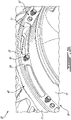
FIGS. 2A to 2C are rear perspective, rear schematic and cross sectional views, respectively, of a mounting assembly; -
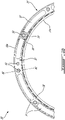
FIG. 3 is a rear schematic view of a component for a mounting assembly; -
FIG. 4 is a rear perspective view of a component for a mounting assembly; -
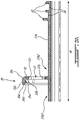
FIGS. 5A and5B are cross sectional views of a component for a mounting assembly taken along lines VA and VB, respectively, ofFIG. 3 ; -
FIG. 6 is an enlarged rear schematic view of a component for a mounting assembly; and -
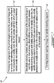
FIG. 7 is a flow diagram of an exemplary method for forming one or more arcuate cutouts in a component for a mounting assembly. -
FIG. 1 illustrates agas turbine engine 10 of a type preferably provided for use in subsonic flight, generally comprising in serial flow communication afan 12 through which ambient air is propelled, acompressor section 14 for pressurizing the air, acombustor 16 in which the compressed air is mixed with fuel and ignited for generating an annular stream of hot combustion gases, and aturbine section 18 for extracting energy from the combustion gases. AlthoughFIG. 1 shows a turbofan-type engine, the present disclosure is also applicable to other types of aircrafts. - Referring to
FIGS. 2A-2C , amounting assembly 20 for interconnecting or joining two components inengine 10 is shown.Mounting assembly 20, also referred to as amating assembly 20, includes afirst component 30 which is mated or joined to asecond component 40, illustratively via threadedfasteners 50. As will be discussed in further detail below, in various embodiments thefirst component 30 andsecond component 40 are additionally retained together via one or more annular flanges creating an interference or spigot-fit between radially outer circumferences of the one or more mating flanges. Themounting assembly 20 may be located at various locations within theengine 10, for instance at an inlet to thecompressor section 14. Other locations for themounting assembly 20 may be contemplated as well. - Referring additionally to
FIGS. 3-5B , the shownfirst component 30 includes anannular body 31 disposed about a center C. In the illustrated embodiment, although not necessarily the case in all embodiments, acentral axis 11 of the engine 10 (FIG. 1 ) passes through the center C of theannular body 31. Theannular body 31 includes a radially-innercircumferential surface 31a and a radially-outercircumferential surface 31b. Thefirst component 30 includes anannular flange 32 protruding axially from the radially-outercircumferential surface 31b of theannular body 31 and is circumferentially disposed about theannular body 31. Theannular flange 32 is operable to receive and abut against a corresponding surface of thesecond component 40, as shown inFIG. 2C and as will be discussed in further detail below. - The
annular flange 32, also referred to as an annular wall, divides the radially-outercircumferential surface 31b into a first side 31b1 and a second side 31b2. The first side 31b1, also referred to as the front side of theflange 32, is operable to receive thesecond component 40. The second side 31b2, also referred to as the rear side of theflange 32, illustratively includes additional radially-outward extendingportions 33 andslots 34. Such radially-outward extendingportions 33 andslots 34 may, for instance, be operable to allow thefirst component 30 engage with additional components of theengine 10. Additional or other features on the the first side 31b1 and/or second side 31b2 may be present as well. An axial width W of theannular body 31 may vary, for instance based on the location and nature of themating assembly 20 within theengine 10. - As best shown in
FIGS. 5A-5B , thefirst component 30 includes, at a radiallyouter rim 32a of theannular flange 32, aspigot 35. Thespigot 35, also referred to as an outer peripheral rim, extends axially from the radiallyouter rim 32a of theannular flange 32, illustratively towards the first side 31b1. The shownspigot 35 includes a radiallyinner spigot surface 35a forming a ninety degree angle with anaxial face 32b on a first side 31b1 surface of theannular flange 32. This corner may be curved, as shown inFIGS. 5A-5B . The spigot further includes a radiallyouter spigot surface 35b, and an angled or chamferedouter spigot portion 35c joining the radiallyouter spigot surface 35b with a second side 31b2 surface of theannular flange 32. The axial width ofspigot 35 may vary. In addition, as shown inFIGS. 5A-5B , an additional chamferedportion 35d may join anaxial face 35e at an axial end of thespigot 35 to the radiallyinner spigot surface 35a. Theannular flange 32 further includes a first set ofholes 36 operable to receive threaded fasteners 50 (hereinafter referred to as "fasteners 50") for retaining thefirst component 30 to thesecond component 40, as will be discussed in further detail below. The first set ofholes 36 may also be referred to as fastener openings. The diameters of thevarious holes 36 may vary, for instance to receivefasteners 50 of varying sizes. - Referring to
FIGS. 2A and2C , thesecond component 40 may be any component within theengine 10 that engages and mates with thefirst component 30 via theannular flange 32. For instance, thesecond component 40 may form part of the inlet of thecompressor section 14 of theengine 10. As shown inFIGS. 2A and2C , thesecond component 40 includes anannular body 41 that is operable to engage with theannular flange 32 andspigot 35 of thefirst component 30. Theannular flange 32 is considered an 'outside fit' flange, and as such theannular body 41 is operable to engage with the radiallyouter rim 32a of theannular flange 32 for an interference fit. In particular, anaxial end face 41a of theannular body 41 is operable to abut against theaxial face 32b on the first side 31b1 of theannular flange 32, while the interference fit is created by a radially-outer surface 41b of theannular body 41 abutting or engaging with the radiallyinner spigot surface 35a. In the embodiment shown inFIG. 2C , although not necessarily the case in all embodiments, the radially-outer surface 41b may include a raisedannular shoulder portion 41c to further increase the interference fit. The friction created by this interference fit may prevent the separation of thefirst component 30 and thesecond component 40. This interference fit may centralize thefirst component 30 and thesecond component 40 relative to each other relative to thecentral axis 11, while the contact between theaxial end face 41a and theaxial face 32b of theannular flange 32 may axially locate thefirst component 30 and thesecond component 40 relative to each other. The interference fit is maintained about the entire outer circumference of theannular flange 32, i.e. the radiallyouter rim 32a, in an uninterrupted fashion. - The
second component 40 further includes a second set ofholes 42 passing axially through theaxial end face 41a. The number, diameter and arrangement of the second set ofholes 42 may correspond to the number, diameter and arrangement of the first set ofholes 36 in theannular flange 32 of thefirst component 30. As such, thefasteners 50 are operable to pass through corresponding first set ofholes 36 and second set ofholes 42, thus retaining thefirst component 30 to thesecond component 40 and holding or maintaining the interface between theflange 32 and theannular body 41. In some cases, the second set ofholes 42 may extend only partially through thesecond component 40. In such cases, the second set ofholes 42 may be threaded and thefasteners 50 may be screws. In other cases, the second set ofholes 42 may be located on an annular flange (not shown) on the second component, the second set ofholes 42 being through-holes. In such cases, thefasteners 50 may be bolts that are retained with nuts on an opposite side of the flange of thesecond component 40. Other arrangements may be contemplated as well. - Referring to
FIGS. 3-5B , thefirst component 30 includes one or morearcuate cutouts 37 about the circumference of theannular flange 32. Thecutouts 37 may also be referred to as windows, as they pass through theannular flange 32 from the first side 31b1 to the second side 31b2. Thecutouts 37 are each defined by a radial height H1 and an arc length L1 (seeFIG. 3 ). In some embodiments, thecutouts 37 may all be equal, i.e. having the same radial height H1 and arc length L1. In other embodiments, for instance in thefirst component 30 shown inFIG. 2B , thecutouts 37 may have different dimensions from one another. In some cases, thecutouts 37 may have fully roundedcorners 37a, as shown inFIG. 4 . In other cases, some or all of thecorners 37a may be squared or angled. Thecutouts 37 may be formed via material removal from theannular flange 32 to reduce the overall weight of thefirst component 30, as will be discussed in further detail below. - Radially-extending
supports 38 are circumferentially spaced apart betweenadjacent cutouts 37. These supports 38 extend radially between theannular body 31 and the radiallyouter rim 32a of theannular flange 32. As best shown inFIGS. 3-4 , the first set ofholes 36 are located on thesupports 38. The number ofsupports 38 may vary, and thesupports 38 are each defined by a radial height H2 and a width or arc length L2 (seeFIG. 3 ). In some cases, thesupports 38 may all be equivalently sized, while in other cases thesupports 38 may be dimensioned differently from one another. As best shown inFIG. 4 , in the radial heights H2 of the depicted supports 38 are all equal, as they each extend from theannular body 31 to the radiallyouter rim 32a. In other cases, for instance where theannular body 31 included a raised shoulder portion (not shown), somesupports 38 may include lesser radial heights H2 than others. The arc lengths L2 may vary from onesupport 38 to the other. For instance, as shown inFIG. 4 , the number ofholes 36 on a givensupport 38 may require a greater arc length L2. As shown inFIG. 4 , some supports 38 (i.e. a first group of supports 38) may include asingle hole 36 while other supports (i.e. a second group of supports 38) may include two adjacent or side-by-side holes 36. Radially-alignedholes 36 on a givensupport 38 may be contemplated as well. Additionally or alternatively, the number and sizing ofcutouts 37 may affect the number and arc lengths L2 ofsupports 38, as thesupports 38 are formed by the leftover material that is not removed when thecutouts 37 are formed. Other factors affecting the number and sizing of thesupports 38 may be contemplated as well. - In an assembled configuration and while the
engine 10 is powered on, the mountingassembly 20, and in particular theannular flange 32, is subject to various stresses. As such, by maintaining a constant outer periphery at the interference fit at the radiallyouter rim 32a, theannular flange 32 may be able to withstand such stresses. For instance, despite the removal of material for thecutouts 37, thesupports 38 and the consistent radiallyouter rim 32a may provide sufficient hoop strength to theannular flange 32 so that the radiallyouter rim 32a does not bend inward under stress. The consistent radiallyouter rim 32a additionally may provide a constant interference fit between the radially-outer surface 41b of the second component and thespigot 35. - Various methods for removing material to create the
cutouts 37 in theannular flange 32 may be contemplated. For instance, traditional machining techniques such as milling may be used. Alternatively, thecutouts 37 may be formed in theannular flange 32 via laser-cutting. Other techniques may be contemplated as well. As material is removed to form thecutouts 37 between theannular body 31 and the radiallyouter rim 32a, enough material is left at the radiallyouter rim 32a to provide sufficient strength to the radiallyouter rim 32a and to ensure that the radiallyouter rim 32a is circumferentially continuous or uninterrupted (i.e. the radial height H1 of eachcutout 37 is defined). In an embodiment, a bolt pattern is predetermined for theannular flange 32 and the first set ofholes 36 are drilled. Then, material is removed from theannular flange 32 betweenadjacent holes 36 to create thecutouts 37. The arc lengths L1 of thevarious cutouts 37 may be selected based on required arc lengths L2 ofsupports 38, for instance based on the structural requirements of theannular flange 32. Other methods for forming thecutouts 37 may be contemplated as well. For instance, the bolt pattern and arrangement ofcutouts 37 may be optimized for sufficient retention between thefirst component 30 andsecond component 40 and for adequate weight reduction of theannular flange 32. Various materials such as steel, nickel and titanium may be contemplated for the first andsecond components engine 10. - Referring to
FIG. 6 , in some embodiments thecutouts 37 includelocal webbings 39. Thesewebbings 39, also referred to as webs, may provide additional stiffness to theannular flange 32, for instance in cases whererespective cutouts 37 are relatively wide (i.e. with large arc lengths L1). In the embodiment shown inFIG. 6 , thewebbing 39 is an additional radial support subdividing acutout 37 and extending between a radially-inner edge 37b of thecutout 37 to a radially-outer edge 37c of thecutout 37, although other types oflocal webbing 39 may be contemplated as well. For instance, in some embodiments a givencutout 37 may include more than onewebbing 39. The number of support webbings 39 in a givencutout 37 may vary based on the arc length L1 of thatcutout 37, wherein awider cutout 37 may require a greater number ofwebbings 39 for sufficient support. In other embodiments, thewebbings 39 may be angled rather than extending in a radial direction. In some embodiments, webbings 39 in a givencutout 37 may intersect as well.Other webbing 39 patterns may be contemplated as well. In the embodiment shown inFIG. 6 , each intersectedcutout 37 includes radially inner corners (i.e. along radiallyinner edges 37c) and two radially outer corners (i.e. along radiallyouter edges 37c), the two radially outer corners having tighter radii than the two radially inner corners. - As shown in
FIG. 6 , thewebbings 39 may be narrower (i.e. in a circumferential direction) than thesupports 38. In addition, in the embodiment shown inFIG. 6 , thewebbings 39 do not includeholes 36 forfasteners 50. In some embodiments, each of thecutouts 37 includewebbings 39. In other embodiments, some of thecutouts 37 may includewebbings 39, for instance those that meet a minimum arc length L1 threshold, while othernarrower cutouts 37 may not includewebbings 39. Thewebbings 39 may be fashioned during the material removal process during which thecutouts 37 are formed. For instance, rather than machining asingle cutout 37 betweenadjacent holes 36,adjacent cutouts 37 withwebbing 39 therebetween may be formed. Other methods for forming thewebbings 39 may be contemplated as well. - Referring to
FIG. 7 , anexemplary method 100 for forming one or morearcuate cutouts 37 in anannular flange 32 disposed about a radiallyouter surface 31b of acomponent 30 of anaircraft engine 10 is shown. Atstep 102, thecomponent 30 of theaircraft engine 10 is provided having theannular flange 32 with an annular wall extending radially outwardly from the radiallyouter surface 31b of thecomponent 30 to a radiallyouter rim 32a of the annular wall from which aspigot 35 extends axially and extends circumferentially about an entire circumference thereof. Atstep 104, material is selectively removed along a circumference of theannular flange 32 to form the one or morearcuate cutouts 37 defined circumferentially between radially-extendingsupports 38 and radially inwards of the radiallyouter rim 32a, the radially-extendingsupports 38 circumferentially spaced and extending radially between the radiallyouter surface 31b of thecomponent 30 and the radiallyouter rim 32a of the annular wall. Atstep 106, holes orfastener openings 36 are formed through the radially-extendingsupports 38. Additional and/or alternative steps may be contemplated as well. - The embodiments described in this document provide non-limiting examples of possible implementations of the present technology. Upon review of the present disclosure, a person of ordinary skill in the art will recognize that changes may be made to the embodiments described herein without departing from the scope of the present technology. Yet further modifications could be implemented by a person of ordinary skill in the art in view of the present disclosure, which modifications would be within the scope of the present technology.
Claims (13)
- A component (30) of an aircraft engine (10) having an annular flange (32) disposed about a radially outer surface (31b) of the component (30), the annular flange (32) comprising:an annular wall extending radially outwardly from the radially outer surface (31b) of the component (30), the annular wall including radially-extending supports (38) circumferentially spaced apart and extending radially between the radially outer surface (31b) of the component (30) and a circumferentially uninterrupted radially outer rim (32a) of the annular wall, the annular wall including one or more arcuate cutouts (37) defined circumferentially between adjacent radially-extending supports (38) and radially inwards of the radially outer rim (32a) of the annular wall, the radially-extending supports (38) including fastener openings (36) defined axially therethrough; anda spigot (35) extending axially from the radially outer rim (32a) of the annular wall, the spigot (35) extending circumferentially about an entire circumference of the radially outer rim (32a) of the annular wall.
- The component (30) of an aircraft engine (10) as defined in claim 1, further comprising one or more radially-extending webs (39) circumferentially subdividing the one or more arcuate cutouts (37), the radially-extending webs (39) extending from radially-inner edges (37b) of the one or more arcuate cutouts (37) to radially-outer edges (37c) of the one or more arcuate cutouts (37).
- The component (30) of an aircraft engine (10) as defined in claim 2, wherein the radially-extending webs (39) subdivide the one or more of the arcuate cutouts (37) into two equal portions.
- The component (30) of an aircraft engine (10) as defined in any one of the preceding claims, wherein each of the one or more arcuate cutouts (37) include two radially inner corners and two radially outer corners, the two radially outer corners having tighter radii than the two radially inner corners.
- The component (30) of an aircraft engine (10) as defined in any one of the preceding claims, wherein a first group of the radially-extending supports (38) each include a single fastener opening (36) defined axially therethrough and a second group of the radially-extending supports (38) each include a pair of fastener openings (36) defined axially therethrough.
- The component (30) of an aircraft engine (10) as defined in claim 5, wherein the pairs of fastener openings (36) on the second group of radially-extending supports (38) are circumferentially adjacent.
- The component (30) of an aircraft engine (10) as defined in any one of the preceding claims, wherein all of the one or more arcuate cutouts (37) have equivalent arc lengths (L1).
- The component (30) of an aircraft engine (10) as defined in any one of the preceding claims, wherein all of the radially extending supports (38) have equivalent widths (L2).
- The component (30) of an aircraft engine (10) as defined in any one of the preceding claims, wherein the spigot (35) includes a radially inner spigot surface (35a), a radially outer spigot surface (35b) parallel to the radially inner spigot surface (35a), an axial end face (35e) joining the radially inner spigot surface (35a) to the radially outer spigot surface (35b), and a chamfered portion (35c) joining the radially outer spigot surface (35b) to the annular wall.
- The component (30) of an aircraft engine (10) as defined in claim 9, wherein the spigot (35) further includes an additional chamfered portion (35d) joining the axial end face (35e) to the radially inner spigot surface (35a).
- The component (30) of an aircraft engine (10) as defined in any one of the preceding claims, wherein the one or more arcuate cutouts (37) are machined or laser-cut into the annular wall.
- A mating assembly (20) in an aircraft engine (10), comprising:the component (30) as defined in any one of the preceding claims;a second component (40) having an annular body (41) with a radially-outer surface (41b) and an axial end face (41a) with a second set of holes (42) disposed about a circumference of the annular body (41), the radially-outer surface (41b) engaging a radially inner surface (35a) of the spigot (35) of the component (30), the axial end face (41a) engaging an axial face (32b) of the annular flange (32) of the component (30), with the second set of holes (42) circumferentially aligned with the fastener openings (36); andthreaded fasteners (50) received through the fastener openings (36) and the second set of holes (42), the threaded fasteners (50) axially retaining the component (30) and the second component (40) together.
- A method for forming an annular flange (32) disposed about a radially outer surface (31b) of a component (30) of an aircraft engine (10), comprising:providing the component (30) of the aircraft engine (10) having the annular flange (32) with an annular wall extending radially outwardly from the radially outer surface (31b) of the component (30) to a radially outer rim (32a) of the annular wall from which a spigot (35) extends axially and extends circumferentially about an entire circumference thereof;selectively removing material along a portion of a circumference of the annular flange (32) to form one or more arcuate cutouts (37) defined circumferentially between radially-extending supports (38) and radially inwards of the radially outer rim (32a), the radially-extending supports (38) circumferentially spaced and extending radially between the radially outer surface (31b) of the component (30) and the radially outer rim (32a) of the annular wall; andforming fastener openings (36) through the radially-extending supports (38).
Applications Claiming Priority (1)
| Application Number | Priority Date | Filing Date | Title |
|---|---|---|---|
| US17/363,384 US20230003141A1 (en) | 2021-06-30 | 2021-06-30 | Outside fit flange for aircraft engine |
Publications (1)
| Publication Number | Publication Date |
|---|---|
| EP4112889A1 true EP4112889A1 (en) | 2023-01-04 |
Family
ID=82493900
Family Applications (1)
| Application Number | Title | Priority Date | Filing Date |
|---|---|---|---|
| EP22182403.0A Withdrawn EP4112889A1 (en) | 2021-06-30 | 2022-06-30 | Outside fit flange for aircraft engine |
Country Status (3)
| Country | Link |
|---|---|
| US (1) | US20230003141A1 (en) |
| EP (1) | EP4112889A1 (en) |
| CA (1) | CA3159590A1 (en) |
Families Citing this family (1)
| Publication number | Priority date | Publication date | Assignee | Title |
|---|---|---|---|---|
| US12448904B1 (en) | 2024-09-27 | 2025-10-21 | Pratt & Whitney Canada Corp. | Seal assembly mating plate for aircraft powerplant |
Citations (4)
| Publication number | Priority date | Publication date | Assignee | Title |
|---|---|---|---|---|
| US20040033133A1 (en) * | 2002-08-15 | 2004-02-19 | General Electric Company | Compressor bleed case |
| EP1475515A2 (en) * | 2003-05-06 | 2004-11-10 | General Electric Company | Apparatus for controlling rotor blade tip clearances in a gas turbine engine |
| US20140260321A1 (en) * | 2013-03-15 | 2014-09-18 | United Technologies Corporation | Gas turbine engine static structure joint with undercuts |
| US20190128282A1 (en) * | 2016-02-18 | 2019-05-02 | Pratt & Whitney Canada Corp. | Intermittent spigot joint for gas turbine engine casing connection |
Family Cites Families (5)
| Publication number | Priority date | Publication date | Assignee | Title |
|---|---|---|---|---|
| BR0008359A (en) * | 1999-01-25 | 2001-11-27 | Elliott Turbo | Housing for rotating machines, method for manufacturing a portion of housing and high pressure housing |
| FR2857409B1 (en) * | 2003-07-11 | 2006-07-28 | Snecma Moteurs | DEVICE FOR PASSIVELY PILOTING THE THERMAL EXPANSION OF THE EXPANSION BOX OF A TURBOREACTOR |
| FR2978734B1 (en) * | 2011-08-05 | 2015-01-02 | Airbus Operations Sas | CONNECTION DEVICE PARTICULARLY ADAPTED TO ENSURE THE CONNECTION BETWEEN AN AIR INLET AND A MOTORIZATION OF AN AIRCRAFT NACELLE |
| FR2998546B1 (en) * | 2012-11-23 | 2016-01-01 | Airbus Operations Sas | AIRCRAFT NACELLE INCORPORATING AN IMPROVED CONNECTION BETWEEN AN AIR INLET AND A MOTORIZATION |
| DE102015219954A1 (en) * | 2015-10-14 | 2017-04-20 | Rolls-Royce Deutschland Ltd & Co Kg | Assembly for the rotationally fixed connection of at least two rotating components in a gas turbine and balancing method |
-
2021
- 2021-06-30 US US17/363,384 patent/US20230003141A1/en not_active Abandoned
-
2022
- 2022-05-18 CA CA3159590A patent/CA3159590A1/en active Pending
- 2022-06-30 EP EP22182403.0A patent/EP4112889A1/en not_active Withdrawn
Patent Citations (4)
| Publication number | Priority date | Publication date | Assignee | Title |
|---|---|---|---|---|
| US20040033133A1 (en) * | 2002-08-15 | 2004-02-19 | General Electric Company | Compressor bleed case |
| EP1475515A2 (en) * | 2003-05-06 | 2004-11-10 | General Electric Company | Apparatus for controlling rotor blade tip clearances in a gas turbine engine |
| US20140260321A1 (en) * | 2013-03-15 | 2014-09-18 | United Technologies Corporation | Gas turbine engine static structure joint with undercuts |
| US20190128282A1 (en) * | 2016-02-18 | 2019-05-02 | Pratt & Whitney Canada Corp. | Intermittent spigot joint for gas turbine engine casing connection |
Also Published As
| Publication number | Publication date |
|---|---|
| CA3159590A1 (en) | 2022-12-30 |
| US20230003141A1 (en) | 2023-01-05 |
Similar Documents
| Publication | Publication Date | Title |
|---|---|---|
| CA2809987C (en) | Structural case for aircraft gas turbine engine | |
| US5438756A (en) | Method for assembling a turbine frame assembly | |
| US8506253B2 (en) | Balancing apparatus for rotor assembly | |
| US5222360A (en) | Apparatus for removably attaching a core frame to a vane frame with a stable mid ring | |
| CA2677372C (en) | Combustor liner with integrated anti-rotation and removal feature | |
| EP2096029A2 (en) | Nose cone assembly and gas turbine engine comprising such an assemby | |
| US11261757B2 (en) | Boss for gas turbine engine | |
| EP3026212B1 (en) | Blisk rim face undercut | |
| EP3279567A1 (en) | A method of assembling an annular combustion chamber assembly | |
| EP3276263B1 (en) | A combustion chamber | |
| EP1462664A2 (en) | Methods and apparatus for joining gas turbine parts together | |
| CA2958347A1 (en) | Intermittent spigot joint for gas turbine engine casing connection | |
| JP2008122068A (en) | Combustor dome mixer holding means | |
| CA3159590A1 (en) | Outside fit flange for aircraft engine | |
| EP2192268A2 (en) | Method and system for cooling turbine engine components | |
| EP4446565A1 (en) | Deswirl system for gas turbine engine | |
| JP4749313B2 (en) | Combustor dome repair method | |
| EP0516389B1 (en) | Apparatus for emovably attaching a core frame to a vane frame with a stable mid ring | |
| US11873725B2 (en) | Fastener cover for flanged joint | |
| EP3611346A1 (en) | Diffuser having platform vanes | |
| EP3971404A1 (en) | Exhaust duct of gas turbine engine | |
| EP3660272B1 (en) | Inter-compressor flow divider profiling | |
| EP2855896B1 (en) | Stator vane mistake proofing | |
| US12305528B2 (en) | Rotor assembly for gas turbine engines with replaceable balance weight bands | |
| EP4036372B1 (en) | Rotor balance assembly |
Legal Events
| Date | Code | Title | Description |
|---|---|---|---|
| PUAI | Public reference made under article 153(3) epc to a published international application that has entered the european phase |
Free format text: ORIGINAL CODE: 0009012 |
|
| STAA | Information on the status of an ep patent application or granted ep patent |
Free format text: STATUS: THE APPLICATION HAS BEEN PUBLISHED |
|
| AK | Designated contracting states |
Kind code of ref document: A1 Designated state(s): AL AT BE BG CH CY CZ DE DK EE ES FI FR GB GR HR HU IE IS IT LI LT LU LV MC MK MT NL NO PL PT RO RS SE SI SK SM TR |
|
| STAA | Information on the status of an ep patent application or granted ep patent |
Free format text: STATUS: THE APPLICATION IS DEEMED TO BE WITHDRAWN |
|
| 18D | Application deemed to be withdrawn |
Effective date: 20230705 |