EP4112803A1 - Pump and washing device including pump - Google Patents
Pump and washing device including pump Download PDFInfo
- Publication number
- EP4112803A1 EP4112803A1 EP22178488.7A EP22178488A EP4112803A1 EP 4112803 A1 EP4112803 A1 EP 4112803A1 EP 22178488 A EP22178488 A EP 22178488A EP 4112803 A1 EP4112803 A1 EP 4112803A1
- Authority
- EP
- European Patent Office
- Prior art keywords
- impeller chamber
- impeller
- fluid
- pipeline
- pump
- Prior art date
- Legal status (The legal status is an assumption and is not a legal conclusion. Google has not performed a legal analysis and makes no representation as to the accuracy of the status listed.)
- Granted
Links
Images


Classifications
-
- F—MECHANICAL ENGINEERING; LIGHTING; HEATING; WEAPONS; BLASTING
- F04—POSITIVE - DISPLACEMENT MACHINES FOR LIQUIDS; PUMPS FOR LIQUIDS OR ELASTIC FLUIDS
- F04D—NON-POSITIVE-DISPLACEMENT PUMPS
- F04D1/00—Radial-flow pumps, e.g. centrifugal pumps; Helico-centrifugal pumps
-
- F—MECHANICAL ENGINEERING; LIGHTING; HEATING; WEAPONS; BLASTING
- F04—POSITIVE - DISPLACEMENT MACHINES FOR LIQUIDS; PUMPS FOR LIQUIDS OR ELASTIC FLUIDS
- F04C—ROTARY-PISTON, OR OSCILLATING-PISTON, POSITIVE-DISPLACEMENT MACHINES FOR LIQUIDS; ROTARY-PISTON, OR OSCILLATING-PISTON, POSITIVE-DISPLACEMENT PUMPS
- F04C19/00—Rotary-piston pumps with fluid ring or the like, specially adapted for elastic fluids
- F04C19/005—Details concerning the admission or discharge
- F04C19/007—Port members in the form of side plates
-
- F—MECHANICAL ENGINEERING; LIGHTING; HEATING; WEAPONS; BLASTING
- F04—POSITIVE - DISPLACEMENT MACHINES FOR LIQUIDS; PUMPS FOR LIQUIDS OR ELASTIC FLUIDS
- F04D—NON-POSITIVE-DISPLACEMENT PUMPS
- F04D15/00—Control, e.g. regulation, of pumps, pumping installations or systems
- F04D15/0005—Control, e.g. regulation, of pumps, pumping installations or systems by using valves
-
- F—MECHANICAL ENGINEERING; LIGHTING; HEATING; WEAPONS; BLASTING
- F04—POSITIVE - DISPLACEMENT MACHINES FOR LIQUIDS; PUMPS FOR LIQUIDS OR ELASTIC FLUIDS
- F04D—NON-POSITIVE-DISPLACEMENT PUMPS
- F04D29/00—Details, component parts, or accessories
- F04D29/40—Casings; Connections of working fluid
- F04D29/42—Casings; Connections of working fluid for radial or helico-centrifugal pumps
- F04D29/426—Casings; Connections of working fluid for radial or helico-centrifugal pumps especially adapted for liquid pumps
- F04D29/4293—Details of fluid inlet or outlet
-
- D—TEXTILES; PAPER
- D06—TREATMENT OF TEXTILES OR THE LIKE; LAUNDERING; FLEXIBLE MATERIALS NOT OTHERWISE PROVIDED FOR
- D06F—LAUNDERING, DRYING, IRONING, PRESSING OR FOLDING TEXTILE ARTICLES
- D06F39/00—Details of washing machines not specific to a single type of machines covered by groups D06F9/00 - D06F27/00
- D06F39/08—Liquid supply or discharge arrangements
- D06F39/083—Liquid discharge or recirculation arrangements
- D06F39/085—Arrangements or adaptations of pumps
Definitions
- the present invention relates to a pump, and further, to a washing device including a pump.
- a pump is relatively widely applied as a fluid driving device, and is generally used for driving liquid to flow.
- the pump is also commonly used in the field of household appliances such as washing devices.
- the pump may be used for draining water or generating a circulating washing liquid flow path.
- the pump generally used for driving liquid cannot be used for driving an airflow simultaneously, especially because suction of the pump is not sufficient to perform air pumping on an enclosed space, thereby generating a negative pressure in the enclosed space.
- An objective of the present invention is to provide an improved pump.
- An embodiment of the present invention includes a pump, including a motor, an impeller driven to rotate by the motor, and an impeller chamber arranged around the impeller.
- the impeller chamber includes a peripheral wall located on an outer side of the impeller in a radial direction, and an end wall located on an outer side of the impeller in an axial direction and opposite to the motor, where a fluid inlet and a first fluid outlet spaced apart from each other are arranged on the end wall, and an edge of the first fluid outlet and the peripheral wall are kept an interval distance from each other in the radial direction.
- an inlet connection port is disposed on the fluid inlet, and a cross-section of the inlet connection port changes from small to large along a direction in which fluid flows into the impeller chamber.
- a first outlet connection port is disposed on the first fluid outlet, and a cross-section of the first outlet connection port changes from large to small along a direction in which the fluid flows out of the impeller chamber.
- An optional embodiment includes that, a second fluid outlet is arranged on the peripheral wall of the impeller chamber, a second outlet connection port is disposed on the second fluid outlet, and the second outlet connection port substantially extends along a tangential direction of the peripheral wall.
- the pump in the embodiments of the present invention can not only drive liquid to flow, but also may generate a water ring in the peripheral wall of the impeller chamber due to a high-speed rotation of the impeller and a reserved distance between the edge of the first fluid outlet and the peripheral wall of the impeller chamber.
- a width of the water ring is related to the distance between the first fluid outlet and the peripheral wall.
- An objective of the present invention further includes providing an improved washing device.
- An embodiment of the present invention further includes a washing device, including a control device and a washing drum, where the pump of the foregoing various embodiments and combinations is fluidly connected to the washing drum.
- An optional embodiment further includes that, the first fluid outlet is connected to a first pipeline, and a first valve is disposed on the first pipeline; the second fluid outlet is connected to a second pipeline, and a second valve is disposed on the second pipeline; and the control device is configured to switch on the first valve and the second valve alternatively or simultaneously.
- An embodiment of the present invention further includes that, a water supply unit and the impeller chamber are connected by a fourth pipeline, and the control device is configured to perform an air pumping process on the washing drum, where, during the air pumping process, in a direction in which fluid is released outward from the impeller chamber, the impeller chamber only keeps the first fluid outlet in fluid communication with the outside, and the water supply unit is intermittently switched on, so that the water supply unit intermittently supplies water to the impeller chamber and meanwhile the fluid inlet is kept in fluid communication with the washing drum.
- An optional embodiment further includes that, the fluid inlet is connected to the washing drum by a third pipeline, and the fourth pipeline is connected to the third pipeline and then connected to the impeller chamber.
- Another embodiment further includes that, an enclosed space is formable in the washing drum.
- An optional embodiment further includes that, the washing drum includes a wall made of a flexible material.
- An optional embodiment further includes that, a second fluid outlet is arranged on the peripheral wall of the impeller chamber, the second fluid outlet is connected to a second pipeline, a second valve is disposed on the second pipeline, and the control device switches off the second valve during the air pumping process.
- the washing device in various embodiments of the present invention may perform water pumping and/or air pumping on the washing drum, thereby forming a negative pressure in the washing drum, which is extremely advantageous for a situation in which the negative pressure needs to be formed in the washing drum.
- the water pumping and the air pumping may be simultaneously implemented with one pump. For example, when the washing drum is at least partially made of the flexible material, and the enclosed space is formed inside, the wall of the washing drum may be deformed, laundry is squeezed, a washing effect is enhanced, or the laundry is dehydrated.
- the water supply unit is connected to the impeller chamber, and is intermittently switched on during the air pumping process. Therefore, when the water supply unit is switched on, water enters the impeller chamber, and a water ring is generated under the driving of the impeller; or when the water ring already exists, replenished water breaks a balance of the water ring instantaneously, to generate a thicker water ring, and an air space in the impeller chamber is compressed, to generate a higher air pressure.
- a width of the water ring exceeds the edge of the first fluid outlet, so water of an added width part is discharged from the first fluid outlet under the action of a high air pressure, while a part of the water ring remains, and the space in the impeller chamber increases.
- the air space in the impeller chamber is continuously compressed and expanded alternately.
- the impeller chamber has a momentarily increased air pressure, which generates a strong propulsion force toward the first fluid outlet for the air.
- the pump may generate a strong air pumping effect on the washing drum.
- a washing device 1 includes a washing drum 2. Laundry is washed and/or undergoes other treatment in the washing drum 2.
- the washing device 1 further includes a control device 3, which controls an electrical element and an electronic element in the washing device 1, and executes a laundry treatment program.
- a pump 4 is fluidly connected to the washing drum 2, so that water pumping and/or air pumping may be performed in the washing drum 2.
- outward drainage is performed by using the pump 4; or a circulating water path is formed by using the pump 4; or the pump 4 continues to be kept switched on after the drainage is completed, so as to perform the air pumping outward; or the pump 4 is switched on when there is no water in the washing drum 2, and the air pumping process is performed independently.
- an enclosed space is formable in the washing drum 2.
- a negative pressure is formed in the washing drum 2 if the pump 4 performs the air pumping outward, which is advantageous for a function or an application that needs a negative pressure scenario.
- the washing drum 2 includes a wall 21 made of a flexible material. Then the pump performs the air pumping outward to deform the wall 21, to squeeze the laundry, which is advantageous for washing or dehydration.
- the enclosed space is not formed in the washing drum 2
- a small amount of water is still contained in the laundry after the pump completes or nearly completes the drainage.
- the pump 4 continues to be kept switched on, so that an airflow may pass through the laundry, and under the action of suction, the water in the laundry may be further dehydrated under the air pressure, and then be discharged as the airflow enters the pump 4.
- the pump 4 may be improved as described below.
- a pump 4 includes a motor 41, an impeller 42 driven to rotate by the motor 41, and an impeller chamber 43 arranged around the impeller 42.
- the impeller chamber 43 includes a peripheral wall 431 located on an outer side of the impeller 42 in a radial direction, and an end wall 432 located on an outer side of the impeller 42 in an axial direction and opposite to the motor 41.
- a fluid inlet 433 and a first fluid outlet 434 spaced apart from each other are arranged on end wall 432.
- An edge of the first fluid outlet 434 and the peripheral wall 431 are kept an interval distance D from each other in the radial direction.
- a second fluid outlet 435 may be further arranged on the peripheral wall 431 of the impeller chamber 43. Compared with the first fluid outlet 434, the second fluid outlet 435 arranged on the peripheral wall 431 is in a centrifugal direction of the impeller 42, so that a higher flow rate may be obtained.
- a specific embodiment further includes that an inlet connection port 436 is disposed on the fluid inlet 433.
- a cross-section of the inlet connection port 436 changes from small to large along a direction in which fluid flows into the impeller chamber 43. In this way, an impact force of a water flow on the impeller 42 may be reduced.
- a first outlet connection port 437 is disposed on the first fluid outlet 434.
- a cross-section of the first outlet connection port 437 changes from large to small along a direction in which the fluid flows out of the impeller chamber 43. In this way, the fluid may be accelerated to flow out of the first fluid outlet 434.
- a second outlet connection port 438 is disposed on the second fluid outlet 435. The second outlet connection port 438 substantially extends along a tangential direction of the peripheral wall 431.
- a washing device 1 further includes the following various embodiments.
- the first fluid outlet 434 of the pump 4 is connected to a first pipeline 51.
- a first valve 61 is disposed on the first pipeline 51.
- An end of the first pipeline 51 is connected to an external waste water receiving pipeline, or connected to a water consumption device, or connected to a water storage device, or connected to a washing drum 2 to form a circulation, or the like.
- the specific application manner is not limited.
- the second fluid outlet 435 of the pump is connected to a second pipeline 52.
- a second valve 62 is disposed on the second pipeline 52.
- An end of the second pipeline 52 is connected to the external waste water receiving pipeline, or connected to the water consumption device, or connected to the water storage device, or connected to the washing drum 2 to form a circulation, or the like.
- the specific application manner is not limited.
- the end of the second pipeline 52 may be connected to a foaming device, and then connected to the washing drum 2, so as to use circulating water to generate air bubbles and improve washing efficiency. This is particularly advantageous for the foaming device to generate air bubbles because fluid flows out of the second fluid outlet 435 at a higher flow rate.
- the foaming device may be in a Venturi structure.
- a control device 3 controls switching on or switching off of the first valve 61 and the second valve 62. According to an actual need, the control device 3 is configured to switch on the first valve 61 and the second valve 62 alternatively or simultaneously.
- the fluid inlet 433 is connected to the washing drum 2 by the third pipeline 53, preferably connected to the bottom of the washing drum 2.
- a third valve 63 controlled by the control device 3 is disposed on the third pipeline 53.
- An advantageous improvement further includes that a water supply unit 7 is connected to the impeller chamber 43 by a fourth pipeline 54.
- the control device 3 is configured to perform an air pumping process on the washing drum 2.
- the impeller chamber 43 only keeps the first fluid outlet 434 in fluid communication with the outside, and the water supply unit 7 is intermittently switched on, so that the water supply unit 7 intermittently supplies water to the impeller chamber 43 and meanwhile the fluid inlet 433 is kept in fluid communication with the washing drum 2.
- the water supply unit 7 includes a fourth valve 64.
- the water supply unit 7 further includes a water source 71.
- the water source 71 may be an external public water source, a water storage device, or another form of water source.
- the control device 3 controls switching on or switching off of the fourth valve 64.
- the fourth pipeline 54 is connected to the third pipeline 53, and then connected to the impeller chamber 43.
- the pump 4 When it is only necessary to drain the washing drum 2 or generate circulating water, the pump 4 is switched on, the fourth valve 64 is switched off, the third valve 63 is switched on, and meanwhile the first valve 61 and/or the second valve 62 are switched on.
- the pump 4 When it is only necessary to perform air pumping on the washing drum 2, the pump 4 is switched on, and the second valve 62 is switched off. This is because if the second valve 62 is switched on, a water ring cannot be formed in the impeller chamber 43.
- the first valve 61 and the third valve 63 are switched on. Meanwhile, the water supply unit 7 is switched on intermittently.
- the foregoing description does not contain a sequential relationship. As shown in FIG. 5A to FIG. 5C , before a water supply unit 7 is switched on, there may be no water in an impeller chamber 43, or there may be a small amount of accumulated water at the bottom. After the water supply unit 7 is switched on, a water ring 1A is formed in the impeller chamber 43.
- FIG. 5C schematically illustrates this process.
- a thickened sub-ring 1B is formed inside the water ring 1A.
- the water ring is still integrated, but the thickness is temporarily increased.
- FIG. 5C is only for ease of understanding. In this case, an air space in the impeller chamber 43 is compressed, to generate a higher air pressure.
- a width of the water ring exceeds an edge of the first fluid outlet 434, so water of an added width part is discharged from the first fluid outlet 434 under the action of a high air pressure, while a part of the water ring remains, and a space in the impeller chamber 43 increases instantaneously.
- the air space in the impeller chamber 43 is continuously compressed and expanded alternately.
- the impeller chamber 43 has a momentarily increased air pressure, which generates a strong propulsion force toward the first fluid outlet 434 for the air.
- the pump 4 may generate a strong air pumping effect on the washing drum 2.
- the pump 4 is switched on, the second valve 62 is switched off, and the first valve 61 and the third valve 63 are switched on. Meanwhile, the water supply unit 7 is switched on intermittently.
- the foregoing description does not contain a sequential relationship. A stable water ring 1A has been formed during the drainage phase.
- the water supply unit 7 supplies water intermittently, a same air pumping effect as that described above is achieved.
- the control device 3 should be set to control an amount of supplied water, so that a thickened water ring is generated each time water is supplied, but the impeller chamber 43 is not filled up. If the impeller chamber is filled up, an air pumping path is blocked, to break continuity of the air pumping, and an increased air pressure cannot be formed in the impeller chamber 43.
- a relationship between an amount of water supplied each time and the impeller chamber 43 is related to a volume of the impeller chamber, a unit water flow rate, and a switching-on time of the water supply unit. Generally, it is only necessary to switch on the water supply unit 7 for a short time, for example, for no more than 3 seconds each time the water is supplied intermittently.
- a specific control scheme is designed according to an actual case and based on the foregoing principles.
- the water supply unit 7 may not be included. Compared with the embodiment with the water supply unit 7, an air pumping effect is somewhat weakened, but the air pumping may also be achieved.
Landscapes
- Engineering & Computer Science (AREA)
- Mechanical Engineering (AREA)
- General Engineering & Computer Science (AREA)
- Textile Engineering (AREA)
- Structures Of Non-Positive Displacement Pumps (AREA)
- Detail Structures Of Washing Machines And Dryers (AREA)
Abstract
Description
- The present invention relates to a pump, and further, to a washing device including a pump.
- A pump is relatively widely applied as a fluid driving device, and is generally used for driving liquid to flow. The pump is also commonly used in the field of household appliances such as washing devices. The pump may be used for draining water or generating a circulating washing liquid flow path.
- The pump generally used for driving liquid cannot be used for driving an airflow simultaneously, especially because suction of the pump is not sufficient to perform air pumping on an enclosed space, thereby generating a negative pressure in the enclosed space.
- Therefore, for an application scenario in which both liquid pumping and air pumping are needed, an additional air pumping device is needed in addition to the pump, which inevitably increases space costs and expense costs.
- An objective of the present invention is to provide an improved pump.
- An embodiment of the present invention includes a pump, including a motor, an impeller driven to rotate by the motor, and an impeller chamber arranged around the impeller. The impeller chamber includes a peripheral wall located on an outer side of the impeller in a radial direction, and an end wall located on an outer side of the impeller in an axial direction and opposite to the motor, where a fluid inlet and a first fluid outlet spaced apart from each other are arranged on the end wall, and an edge of the first fluid outlet and the peripheral wall are kept an interval distance from each other in the radial direction.
- In some embodiments, an inlet connection port is disposed on the fluid inlet, and a cross-section of the inlet connection port changes from small to large along a direction in which fluid flows into the impeller chamber.
- In some embodiments, a first outlet connection port is disposed on the first fluid outlet, and a cross-section of the first outlet connection port changes from large to small along a direction in which the fluid flows out of the impeller chamber.
- An optional embodiment includes that, a second fluid outlet is arranged on the peripheral wall of the impeller chamber, a second outlet connection port is disposed on the second fluid outlet, and the second outlet connection port substantially extends along a tangential direction of the peripheral wall.
- The pump in the embodiments of the present invention can not only drive liquid to flow, but also may generate a water ring in the peripheral wall of the impeller chamber due to a high-speed rotation of the impeller and a reserved distance between the edge of the first fluid outlet and the peripheral wall of the impeller chamber. A width of the water ring is related to the distance between the first fluid outlet and the peripheral wall. Then in a subsequent process, when liquid in the chamber connected to the fluid inlet is exhausted or only a small amount of liquid is left, air may be driven to be discharged from the first fluid outlet by using the pump. The water ring makes an air volume in the impeller chamber smaller, so that the impeller has a better effect of driving air.
- An objective of the present invention further includes providing an improved washing device.
- An embodiment of the present invention further includes a washing device, including a control device and a washing drum, where the pump of the foregoing various embodiments and combinations is fluidly connected to the washing drum.
- An optional embodiment further includes that, the first fluid outlet is connected to a first pipeline, and a first valve is disposed on the first pipeline; the second fluid outlet is connected to a second pipeline, and a second valve is disposed on the second pipeline; and the control device is configured to switch on the first valve and the second valve alternatively or simultaneously.
- An embodiment of the present invention further includes that, a water supply unit and the impeller chamber are connected by a fourth pipeline, and the control device is configured to perform an air pumping process on the washing drum, where, during the air pumping process, in a direction in which fluid is released outward from the impeller chamber, the impeller chamber only keeps the first fluid outlet in fluid communication with the outside, and the water supply unit is intermittently switched on, so that the water supply unit intermittently supplies water to the impeller chamber and meanwhile the fluid inlet is kept in fluid communication with the washing drum.
- An optional embodiment further includes that, the fluid inlet is connected to the washing drum by a third pipeline, and the fourth pipeline is connected to the third pipeline and then connected to the impeller chamber.
- Another embodiment further includes that, an enclosed space is formable in the washing drum.
- An optional embodiment further includes that, the washing drum includes a wall made of a flexible material.
- An optional embodiment further includes that, a second fluid outlet is arranged on the peripheral wall of the impeller chamber, the second fluid outlet is connected to a second pipeline, a second valve is disposed on the second pipeline, and the control device switches off the second valve during the air pumping process.
- The foregoing embodiments may be combined in any feasible manner.
- The washing device in various embodiments of the present invention may perform water pumping and/or air pumping on the washing drum, thereby forming a negative pressure in the washing drum, which is extremely advantageous for a situation in which the negative pressure needs to be formed in the washing drum. The water pumping and the air pumping may be simultaneously implemented with one pump. For example, when the washing drum is at least partially made of the flexible material, and the enclosed space is formed inside, the wall of the washing drum may be deformed, laundry is squeezed, a washing effect is enhanced, or the laundry is dehydrated.
- The water supply unit is connected to the impeller chamber, and is intermittently switched on during the air pumping process. Therefore, when the water supply unit is switched on, water enters the impeller chamber, and a water ring is generated under the driving of the impeller; or when the water ring already exists, replenished water breaks a balance of the water ring instantaneously, to generate a thicker water ring, and an air space in the impeller chamber is compressed, to generate a higher air pressure. In this case, a width of the water ring exceeds the edge of the first fluid outlet, so water of an added width part is discharged from the first fluid outlet under the action of a high air pressure, while a part of the water ring remains, and the space in the impeller chamber increases. During switching on and switching off of the water supply unit in each cycle, the air space in the impeller chamber is continuously compressed and expanded alternately. Especially in a compression process, the impeller chamber has a momentarily increased air pressure, which generates a strong propulsion force toward the first fluid outlet for the air. Thereby, the pump may generate a strong air pumping effect on the washing drum.
- Some specific embodiments of the present invention are exemplified below with reference to the accompanying drawings.
-
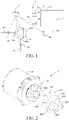
FIG. 1 is a schematic connection diagram of a partial component of a washing device; -
FIG. 2 is a schematic partial exploded diagram of a pump inFIG. 1 ; -
FIG. 3 is a three-dimensional view of an impeller chamber of the pump inFIG. 2 when viewed from the outside; -
FIG. 4 is a three-dimensional view of an impeller chamber of the pump inFIG. 2 when viewed from the inside;FIG. 5A is a front view of an initial state in an impeller chamber; -
FIG. 5B is a front view of a stable water ring formed in an impeller chamber; and -
FIG. 5C is a schematic diagram of an instantaneous state in which an impeller chamber forms a thickened water ring after water enters in the state inFIG. 5B . - As shown in
FIG. 1 , awashing device 1 includes awashing drum 2. Laundry is washed and/or undergoes other treatment in thewashing drum 2. Thewashing device 1 further includes acontrol device 3, which controls an electrical element and an electronic element in thewashing device 1, and executes a laundry treatment program. Apump 4 is fluidly connected to thewashing drum 2, so that water pumping and/or air pumping may be performed in thewashing drum 2. - During a washing process of the laundry in the
washing drum 2 or when a washing program is close to the end, outward drainage is performed by using thepump 4;
or a circulating water path is formed by using thepump 4; or thepump 4 continues to be kept switched on after the drainage is completed, so as to perform the air pumping outward; or thepump 4 is switched on when there is no water in thewashing drum 2, and the air pumping process is performed independently. - In some embodiments, an enclosed space is formable in the
washing drum 2. A negative pressure is formed in thewashing drum 2 if thepump 4 performs the air pumping outward, which is advantageous for a function or an application that needs a negative pressure scenario. Meanwhile, in some embodiments, thewashing drum 2 includes awall 21 made of a flexible material. Then the pump performs the air pumping outward to deform thewall 21, to squeeze the laundry, which is advantageous for washing or dehydration. In the embodiment in which the enclosed space is not formed in thewashing drum 2, a small amount of water is still contained in the laundry after the pump completes or nearly completes the drainage. In this case, thepump 4 continues to be kept switched on, so that an airflow may pass through the laundry, and under the action of suction, the water in the laundry may be further dehydrated under the air pressure, and then be discharged as the airflow enters thepump 4. - To enable the
pump 4 to effectively achieve functions of water pumping and air pumping, preferably thepump 4 may be improved as described below. - For example, as shown in
FIG. 2 to FIG. 4 , apump 4 includes amotor 41, animpeller 42 driven to rotate by themotor 41, and animpeller chamber 43 arranged around theimpeller 42. Theimpeller chamber 43 includes aperipheral wall 431 located on an outer side of theimpeller 42 in a radial direction, and anend wall 432 located on an outer side of theimpeller 42 in an axial direction and opposite to themotor 41. Afluid inlet 433 and afirst fluid outlet 434 spaced apart from each other are arranged onend wall 432. An edge of thefirst fluid outlet 434 and theperipheral wall 431 are kept an interval distance D from each other in the radial direction. - Under a high-speed rotation of the
impeller 42, due to the interval distance D between the edge of thefirst fluid outlet 434 and theperipheral wall 431 of theimpeller chamber 43, when water enters theimpeller chamber 43 from thefluid inlet 433, a water ring with a width close to D is generated in theperipheral wall 431 of theimpeller chamber 43. Then in a subsequent process, when water in awashing drum 2 is exhausted or only a small amount of water is left, air may be driven to be discharged from thefirst fluid outlet 434 by using thepump 4. The water ring makes an air volume in theimpeller chamber 43 smaller, so that theimpeller 42 has a better effect of driving air. - In some embodiments of the present invention, a second
fluid outlet 435 may be further arranged on theperipheral wall 431 of theimpeller chamber 43. Compared with the firstfluid outlet 434, the secondfluid outlet 435 arranged on theperipheral wall 431 is in a centrifugal direction of theimpeller 42, so that a higher flow rate may be obtained. - A specific embodiment further includes that an
inlet connection port 436 is disposed on thefluid inlet 433. A cross-section of theinlet connection port 436 changes from small to large along a direction in which fluid flows into theimpeller chamber 43. In this way, an impact force of a water flow on theimpeller 42 may be reduced. A firstoutlet connection port 437 is disposed on the firstfluid outlet 434. A cross-section of the firstoutlet connection port 437 changes from large to small along a direction in which the fluid flows out of theimpeller chamber 43. In this way, the fluid may be accelerated to flow out of the firstfluid outlet 434. A secondoutlet connection port 438 is disposed on the secondfluid outlet 435. The secondoutlet connection port 438 substantially extends along a tangential direction of theperipheral wall 431. - A
washing device 1 further includes the following various embodiments. - The first
fluid outlet 434 of thepump 4 is connected to afirst pipeline 51. Afirst valve 61 is disposed on thefirst pipeline 51. An end of thefirst pipeline 51 is connected to an external waste water receiving pipeline, or connected to a water consumption device, or connected to a water storage device, or connected to awashing drum 2 to form a circulation, or the like. The specific application manner is not limited. - The second
fluid outlet 435 of the pump is connected to asecond pipeline 52. Asecond valve 62 is disposed on thesecond pipeline 52. An end of thesecond pipeline 52 is connected to the external waste water receiving pipeline, or connected to the water consumption device, or connected to the water storage device, or connected to thewashing drum 2 to form a circulation, or the like. The specific application manner is not limited. The end of thesecond pipeline 52 may be connected to a foaming device, and then connected to thewashing drum 2, so as to use circulating water to generate air bubbles and improve washing efficiency. This is particularly advantageous for the foaming device to generate air bubbles because fluid flows out of the secondfluid outlet 435 at a higher flow rate. The foaming device may be in a Venturi structure. - A
control device 3 controls switching on or switching off of thefirst valve 61 and thesecond valve 62. According to an actual need, thecontrol device 3 is configured to switch on thefirst valve 61 and thesecond valve 62 alternatively or simultaneously. - The
fluid inlet 433 is connected to thewashing drum 2 by thethird pipeline 53, preferably connected to the bottom of thewashing drum 2. - A
third valve 63 controlled by thecontrol device 3 is disposed on thethird pipeline 53. - An advantageous improvement further includes that a
water supply unit 7 is connected to theimpeller chamber 43 by afourth pipeline 54. Thecontrol device 3 is configured to perform an air pumping process on thewashing drum 2. During the air pumping process, in a direction in which a fluid is released outward from theimpeller chamber 43, theimpeller chamber 43 only keeps the firstfluid outlet 434 in fluid communication with the outside, and thewater supply unit 7 is intermittently switched on, so that thewater supply unit 7 intermittently supplies water to theimpeller chamber 43 and meanwhile thefluid inlet 433 is kept in fluid communication with thewashing drum 2. - The
water supply unit 7 includes afourth valve 64. Thewater supply unit 7 further includes awater source 71. Thewater source 71 may be an external public water source, a water storage device, or another form of water source. Thecontrol device 3 controls switching on or switching off of thefourth valve 64. - In a preferable embodiment, the
fourth pipeline 54 is connected to thethird pipeline 53, and then connected to theimpeller chamber 43. - When it is only necessary to drain the
washing drum 2 or generate circulating water, thepump 4 is switched on, thefourth valve 64 is switched off, thethird valve 63 is switched on, and meanwhile thefirst valve 61 and/or thesecond valve 62 are switched on. - When it is only necessary to perform air pumping on the
washing drum 2, thepump 4 is switched on, and thesecond valve 62 is switched off. This is because if thesecond valve 62 is switched on, a water ring cannot be formed in theimpeller chamber 43. Thefirst valve 61 and thethird valve 63 are switched on. Meanwhile, thewater supply unit 7 is switched on intermittently. The foregoing description does not contain a sequential relationship. As shown inFIG. 5A to FIG. 5C , before awater supply unit 7 is switched on, there may be no water in animpeller chamber 43, or there may be a small amount of accumulated water at the bottom. After thewater supply unit 7 is switched on, awater ring 1A is formed in theimpeller chamber 43. When water is supplied next time, replenished water breaks a balance of thewater ring 1A instantaneously, to form a thicker water ring.FIG. 5C schematically illustrates this process. A thickenedsub-ring 1B is formed inside thewater ring 1A. In fact, there is no distinguishingwater ring 1A and sub-ring 1B, the water ring is still integrated, but the thickness is temporarily increased.FIG. 5C is only for ease of understanding. In this case, an air space in theimpeller chamber 43 is compressed, to generate a higher air pressure. In this case, a width of the water ring exceeds an edge of the firstfluid outlet 434, so water of an added width part is discharged from the firstfluid outlet 434 under the action of a high air pressure, while a part of the water ring remains, and a space in theimpeller chamber 43 increases instantaneously. During switching on and switching off of thewater supply unit 7 in each cycle, the air space in theimpeller chamber 43 is continuously compressed and expanded alternately. Especially in a compression process, theimpeller chamber 43 has a momentarily increased air pressure, which generates a strong propulsion force toward the firstfluid outlet 434 for the air. Thereby, thepump 4 may generate a strong air pumping effect on thewashing drum 2. - When the
washing drum 2 needs to be drained, and the air pumping is further performed after the drainage, thepump 4 is switched on, thesecond valve 62 is switched off, and thefirst valve 61 and thethird valve 63 are switched on. Meanwhile, thewater supply unit 7 is switched on intermittently. The foregoing description does not contain a sequential relationship. Astable water ring 1A has been formed during the drainage phase. When thewater supply unit 7 supplies water intermittently, a same air pumping effect as that described above is achieved. - In an intermittent water supply process of the
water supply unit 7 after thewater ring 1A has been stabilized, thecontrol device 3 should be set to control an amount of supplied water, so that a thickened water ring is generated each time water is supplied, but theimpeller chamber 43 is not filled up. If the impeller chamber is filled up, an air pumping path is blocked, to break continuity of the air pumping, and an increased air pressure cannot be formed in theimpeller chamber 43. A relationship between an amount of water supplied each time and theimpeller chamber 43 is related to a volume of the impeller chamber, a unit water flow rate, and a switching-on time of the water supply unit. Generally, it is only necessary to switch on thewater supply unit 7 for a short time, for example, for no more than 3 seconds each time the water is supplied intermittently. A specific control scheme is designed according to an actual case and based on the foregoing principles. - In some embodiments, the
water supply unit 7 may not be included. Compared with the embodiment with thewater supply unit 7, an air pumping effect is somewhat weakened, but the air pumping may also be achieved. - The various specific implementations described above and shown in the accompanying drawings are only used to illustrate the present invention. Any variation made by a person of ordinary skill in the art to the present invention within the scope of the basic technical concept of the present invention shall fall within the protection scope of the present invention.
Claims (11)
- A pump, comprising a motor (41), an impeller (42) driven to rotate by the motor, and an impeller chamber (43) arranged around the impeller, characterized in that the impeller chamber comprises a peripheral wall (431) located on an outer side of the impeller in a radial direction, and an end wall (432) located on an outer side of the impeller in an axial direction and opposite to the motor, wherein a fluid inlet (433) and a first fluid outlet (434) spaced apart from each other are arranged on the end wall, and an edge of the first fluid outlet and the peripheral wall are kept an interval distance (D) from each other in the radial direction.
- The pump according to claim 1, characterized in that an inlet connection port (436) is disposed on the fluid inlet (433), and a cross-section of the inlet connection port changes from small to large along a direction in which fluid flows into the impeller chamber.
- The pump according to claim 2, characterized in that a first outlet connection port (437) is disposed on the first fluid outlet (434), and a cross-section of the first outlet connection port changes from large to small along a direction in which the fluid flows out of the impeller chamber.
- The pump according to claim 1, characterized in that a second fluid outlet (435) is arranged on the peripheral wall of the impeller chamber, a second outlet connection port (438) is disposed on the second fluid outlet, and the second outlet connection port substantially extends along a tangential direction of the peripheral wall.
- A washing device, comprising a control device (3) and a washing drum (2), characterized in that the pump (4) according to any one of claims 1 to 4 is fluidly connected to the washing drum (2).
- The washing device according to claim 5, characterized in that the first fluid outlet (434) is connected to a first pipeline (51), and a first valve (61) is disposed on the first pipeline; the second fluid outlet (435) is connected to a second pipeline (52), and a second valve (62) is disposed on the second pipeline; and the control device is configured to switch on the first valve and the second valve alternatively or simultaneously.
- The washing device according to claim 5, characterized in that a water supply unit (7) and the impeller chamber (43) are connected by a fourth pipeline (54), and the control device is configured to perform an air pumping process on the washing drum (2), wherein, during the air pumping process, in a direction in which fluid is released outward from the impeller chamber, the impeller chamber only keeps the first fluid outlet (434) in fluid communication with the outside, and the water supply unit is intermittently switched on, so that the water supply unit intermittently supplies water to the impeller chamber and meanwhile the fluid inlet (433) is kept in fluid communication with the washing drum.
- The washing device according to claim 7, characterized in that the fluid inlet (433) is connected to the washing drum (2) by a third pipeline (53), and the fourth pipeline (54) is connected to the third pipeline and then connected to the impeller chamber (43).
- The washing device according to claim 7, characterized in that an enclosed space is formable in the washing drum (2).
- The washing device according to claim 9, characterized in that the washing drum (2) comprises a wall (21) made of a flexible material.
- The washing device according to claim 7, characterized in that a second fluid outlet (435) is arranged on the peripheral wall (431) of the impeller chamber, the second fluid outlet is connected to a second pipeline (52), a second valve (62) is disposed on the second pipeline, and the control device switches off the second valve during the air pumping process.
Applications Claiming Priority (1)
| Application Number | Priority Date | Filing Date | Title |
|---|---|---|---|
| CN202110727023.2A CN115538120A (en) | 2021-06-29 | 2021-06-29 | Pump and washing device with same |
Publications (2)
| Publication Number | Publication Date |
|---|---|
| EP4112803A1 true EP4112803A1 (en) | 2023-01-04 |
| EP4112803B1 EP4112803B1 (en) | 2025-08-20 |
Family
ID=82019913
Family Applications (1)
| Application Number | Title | Priority Date | Filing Date |
|---|---|---|---|
| EP22178488.7A Active EP4112803B1 (en) | 2021-06-29 | 2022-06-10 | Pump and washing device including pump |
Country Status (2)
| Country | Link |
|---|---|
| EP (1) | EP4112803B1 (en) |
| CN (1) | CN115538120A (en) |
Citations (3)
| Publication number | Priority date | Publication date | Assignee | Title |
|---|---|---|---|---|
| US3851993A (en) * | 1973-04-16 | 1974-12-03 | Franklin Mfg Co | Washing machine pump |
| EP0466167A2 (en) * | 1990-07-12 | 1992-01-15 | A. Ahlstrom Corporation | Method and apparatus for pumping a medium |
| JP2017038752A (en) * | 2015-08-19 | 2017-02-23 | 日立アプライアンス株式会社 | Washing and drying machine |
Family Cites Families (3)
| Publication number | Priority date | Publication date | Assignee | Title |
|---|---|---|---|---|
| DE2650509A1 (en) * | 1976-11-04 | 1978-05-18 | Emanuel Alder | Washing machine employing a vacuum-operated diaphragm - to force liquid through the clothes and then squeeze them damp-dry |
| US4392783A (en) * | 1980-12-12 | 1983-07-12 | The Nash Engineering Company | Liquid ring pump employing discharged pumping liquid for discharge port control |
| DE20105625U1 (en) * | 2001-03-31 | 2001-11-22 | Pracht Pumpen GmbH, 15907 Lübben | Liquid ring machine |
-
2021
- 2021-06-29 CN CN202110727023.2A patent/CN115538120A/en active Pending
-
2022
- 2022-06-10 EP EP22178488.7A patent/EP4112803B1/en active Active
Patent Citations (3)
| Publication number | Priority date | Publication date | Assignee | Title |
|---|---|---|---|---|
| US3851993A (en) * | 1973-04-16 | 1974-12-03 | Franklin Mfg Co | Washing machine pump |
| EP0466167A2 (en) * | 1990-07-12 | 1992-01-15 | A. Ahlstrom Corporation | Method and apparatus for pumping a medium |
| JP2017038752A (en) * | 2015-08-19 | 2017-02-23 | 日立アプライアンス株式会社 | Washing and drying machine |
Also Published As
| Publication number | Publication date |
|---|---|
| CN115538120A (en) | 2022-12-30 |
| EP4112803B1 (en) | 2025-08-20 |
Similar Documents
| Publication | Publication Date | Title |
|---|---|---|
| JP6956318B2 (en) | Washing machine | |
| EP2009165A1 (en) | Operating cycle for the drain pump of a household washing appliance | |
| JP6480796B2 (en) | Washing machine | |
| CN108342877B (en) | Laundry care appliances with controls | |
| WO2004084699A3 (en) | Washing machine with a dispenser for a diversified dispensing of washing agents, and a device and method for implementation thereof | |
| JP6092014B2 (en) | Washing machine | |
| EP4112803B1 (en) | Pump and washing device including pump | |
| US3867821A (en) | Transmissionless washing machine with modulated recirculation | |
| US3043125A (en) | Clothes washing machine | |
| BRPI0905459A2 (en) | method and washing machine provided with controlled flow recirculation | |
| US6470716B1 (en) | Washing machine with a suppressed discharge-pump noise | |
| KR200464783Y1 (en) | Washing machine and drain pump | |
| EP4112804A1 (en) | Washing device | |
| CN114622373B (en) | Washing control method of cleaning device and cleaning device | |
| CN218492029U (en) | Washing apparatus | |
| JP2016043180A (en) | Washing machine | |
| JP6427759B2 (en) | Washing machine | |
| CN103789971B (en) | Washing machine | |
| JP2005103180A (en) | Washing machine | |
| JP2016043181A (en) | Washing machine | |
| KR20000001877A (en) | Washing machine and washing methodv | |
| JP3125784B2 (en) | Washing machine | |
| JPH0810494A (en) | Washing machine | |
| CN216998928U (en) | Cleaning device | |
| KR200344937Y1 (en) | Washing machine eccentricity correction device of washing machine |
Legal Events
| Date | Code | Title | Description |
|---|---|---|---|
| PUAI | Public reference made under article 153(3) epc to a published international application that has entered the european phase |
Free format text: ORIGINAL CODE: 0009012 |
|
| STAA | Information on the status of an ep patent application or granted ep patent |
Free format text: STATUS: THE APPLICATION HAS BEEN PUBLISHED |
|
| AK | Designated contracting states |
Kind code of ref document: A1 Designated state(s): AL AT BE BG CH CY CZ DE DK EE ES FI FR GB GR HR HU IE IS IT LI LT LU LV MC MK MT NL NO PL PT RO RS SE SI SK SM TR |
|
| STAA | Information on the status of an ep patent application or granted ep patent |
Free format text: STATUS: REQUEST FOR EXAMINATION WAS MADE |
|
| 17P | Request for examination filed |
Effective date: 20230704 |
|
| RBV | Designated contracting states (corrected) |
Designated state(s): AL AT BE BG CH CY CZ DE DK EE ES FI FR GB GR HR HU IE IS IT LI LT LU LV MC MK MT NL NO PL PT RO RS SE SI SK SM TR |
|
| STAA | Information on the status of an ep patent application or granted ep patent |
Free format text: STATUS: EXAMINATION IS IN PROGRESS |
|
| 17Q | First examination report despatched |
Effective date: 20241121 |
|
| REG | Reference to a national code |
Ipc: F04C0019000000 Ref country code: DE Ref legal event code: R079 Ref document number: 602022019677 Country of ref document: DE Free format text: PREVIOUS MAIN CLASS: D06F0039080000 Ipc: F04C0019000000 |
|
| GRAP | Despatch of communication of intention to grant a patent |
Free format text: ORIGINAL CODE: EPIDOSNIGR1 |
|
| STAA | Information on the status of an ep patent application or granted ep patent |
Free format text: STATUS: GRANT OF PATENT IS INTENDED |
|
| RIC1 | Information provided on ipc code assigned before grant |
Ipc: D06F 39/08 20060101ALN20250321BHEP Ipc: F04D 29/42 20060101ALI20250321BHEP Ipc: F04D 15/00 20060101ALI20250321BHEP Ipc: F04D 1/00 20060101ALI20250321BHEP Ipc: F04C 19/00 20060101AFI20250321BHEP |
|
| INTG | Intention to grant announced |
Effective date: 20250411 |
|
| GRAS | Grant fee paid |
Free format text: ORIGINAL CODE: EPIDOSNIGR3 |
|
| GRAA | (expected) grant |
Free format text: ORIGINAL CODE: 0009210 |
|
| STAA | Information on the status of an ep patent application or granted ep patent |
Free format text: STATUS: THE PATENT HAS BEEN GRANTED |
|
| AK | Designated contracting states |
Kind code of ref document: B1 Designated state(s): AL AT BE BG CH CY CZ DE DK EE ES FI FR GB GR HR HU IE IS IT LI LT LU LV MC MK MT NL NO PL PT RO RS SE SI SK SM TR |
|
| REG | Reference to a national code |
Ref country code: GB Ref legal event code: FG4D |
|
| REG | Reference to a national code |
Ref country code: CH Ref legal event code: EP |
|
| REG | Reference to a national code |
Ref country code: DE Ref legal event code: R096 Ref document number: 602022019677 Country of ref document: DE |
|
| REG | Reference to a national code |
Ref country code: IE Ref legal event code: FG4D |
|
| REG | Reference to a national code |
Ref country code: NL Ref legal event code: MP Effective date: 20250820 |
|
| PG25 | Lapsed in a contracting state [announced via postgrant information from national office to epo] |
Ref country code: IS Free format text: LAPSE BECAUSE OF FAILURE TO SUBMIT A TRANSLATION OF THE DESCRIPTION OR TO PAY THE FEE WITHIN THE PRESCRIBED TIME-LIMIT Effective date: 20251220 |
|
| PG25 | Lapsed in a contracting state [announced via postgrant information from national office to epo] |
Ref country code: NO Free format text: LAPSE BECAUSE OF FAILURE TO SUBMIT A TRANSLATION OF THE DESCRIPTION OR TO PAY THE FEE WITHIN THE PRESCRIBED TIME-LIMIT Effective date: 20251120 |
|
| REG | Reference to a national code |
Ref country code: LT Ref legal event code: MG9D |
|
| PG25 | Lapsed in a contracting state [announced via postgrant information from national office to epo] |
Ref country code: PT Free format text: LAPSE BECAUSE OF FAILURE TO SUBMIT A TRANSLATION OF THE DESCRIPTION OR TO PAY THE FEE WITHIN THE PRESCRIBED TIME-LIMIT Effective date: 20251222 |
|
| PG25 | Lapsed in a contracting state [announced via postgrant information from national office to epo] |
Ref country code: FI Free format text: LAPSE BECAUSE OF FAILURE TO SUBMIT A TRANSLATION OF THE DESCRIPTION OR TO PAY THE FEE WITHIN THE PRESCRIBED TIME-LIMIT Effective date: 20250820 |
|
| PG25 | Lapsed in a contracting state [announced via postgrant information from national office to epo] |
Ref country code: HR Free format text: LAPSE BECAUSE OF FAILURE TO SUBMIT A TRANSLATION OF THE DESCRIPTION OR TO PAY THE FEE WITHIN THE PRESCRIBED TIME-LIMIT Effective date: 20250820 Ref country code: NL Free format text: LAPSE BECAUSE OF FAILURE TO SUBMIT A TRANSLATION OF THE DESCRIPTION OR TO PAY THE FEE WITHIN THE PRESCRIBED TIME-LIMIT Effective date: 20250820 |
|
| PG25 | Lapsed in a contracting state [announced via postgrant information from national office to epo] |
Ref country code: GR Free format text: LAPSE BECAUSE OF FAILURE TO SUBMIT A TRANSLATION OF THE DESCRIPTION OR TO PAY THE FEE WITHIN THE PRESCRIBED TIME-LIMIT Effective date: 20251121 |
|
| PG25 | Lapsed in a contracting state [announced via postgrant information from national office to epo] |
Ref country code: SE Free format text: LAPSE BECAUSE OF FAILURE TO SUBMIT A TRANSLATION OF THE DESCRIPTION OR TO PAY THE FEE WITHIN THE PRESCRIBED TIME-LIMIT Effective date: 20250820 |
|
| PG25 | Lapsed in a contracting state [announced via postgrant information from national office to epo] |
Ref country code: LV Free format text: LAPSE BECAUSE OF FAILURE TO SUBMIT A TRANSLATION OF THE DESCRIPTION OR TO PAY THE FEE WITHIN THE PRESCRIBED TIME-LIMIT Effective date: 20250820 |
|
| PG25 | Lapsed in a contracting state [announced via postgrant information from national office to epo] |
Ref country code: BG Free format text: LAPSE BECAUSE OF FAILURE TO SUBMIT A TRANSLATION OF THE DESCRIPTION OR TO PAY THE FEE WITHIN THE PRESCRIBED TIME-LIMIT Effective date: 20250820 Ref country code: PL Free format text: LAPSE BECAUSE OF FAILURE TO SUBMIT A TRANSLATION OF THE DESCRIPTION OR TO PAY THE FEE WITHIN THE PRESCRIBED TIME-LIMIT Effective date: 20250820 |
|
| PG25 | Lapsed in a contracting state [announced via postgrant information from national office to epo] |
Ref country code: RS Free format text: LAPSE BECAUSE OF FAILURE TO SUBMIT A TRANSLATION OF THE DESCRIPTION OR TO PAY THE FEE WITHIN THE PRESCRIBED TIME-LIMIT Effective date: 20251120 |
|
| PG25 | Lapsed in a contracting state [announced via postgrant information from national office to epo] |
Ref country code: ES Free format text: LAPSE BECAUSE OF FAILURE TO SUBMIT A TRANSLATION OF THE DESCRIPTION OR TO PAY THE FEE WITHIN THE PRESCRIBED TIME-LIMIT Effective date: 20250820 |
|
| REG | Reference to a national code |
Ref country code: AT Ref legal event code: MK05 Ref document number: 1827552 Country of ref document: AT Kind code of ref document: T Effective date: 20250820 |
|
| PG25 | Lapsed in a contracting state [announced via postgrant information from national office to epo] |
Ref country code: SM Free format text: LAPSE BECAUSE OF FAILURE TO SUBMIT A TRANSLATION OF THE DESCRIPTION OR TO PAY THE FEE WITHIN THE PRESCRIBED TIME-LIMIT Effective date: 20250820 |
|
| PG25 | Lapsed in a contracting state [announced via postgrant information from national office to epo] |
Ref country code: DK Free format text: LAPSE BECAUSE OF FAILURE TO SUBMIT A TRANSLATION OF THE DESCRIPTION OR TO PAY THE FEE WITHIN THE PRESCRIBED TIME-LIMIT Effective date: 20250820 |
|
| PG25 | Lapsed in a contracting state [announced via postgrant information from national office to epo] |
Ref country code: AT Free format text: LAPSE BECAUSE OF FAILURE TO SUBMIT A TRANSLATION OF THE DESCRIPTION OR TO PAY THE FEE WITHIN THE PRESCRIBED TIME-LIMIT Effective date: 20250820 |
|
| PG25 | Lapsed in a contracting state [announced via postgrant information from national office to epo] |
Ref country code: IT Free format text: LAPSE BECAUSE OF FAILURE TO SUBMIT A TRANSLATION OF THE DESCRIPTION OR TO PAY THE FEE WITHIN THE PRESCRIBED TIME-LIMIT Effective date: 20250820 |
|
| PG25 | Lapsed in a contracting state [announced via postgrant information from national office to epo] |
Ref country code: CZ Free format text: LAPSE BECAUSE OF FAILURE TO SUBMIT A TRANSLATION OF THE DESCRIPTION OR TO PAY THE FEE WITHIN THE PRESCRIBED TIME-LIMIT Effective date: 20250820 |
|
| PG25 | Lapsed in a contracting state [announced via postgrant information from national office to epo] |
Ref country code: EE Free format text: LAPSE BECAUSE OF FAILURE TO SUBMIT A TRANSLATION OF THE DESCRIPTION OR TO PAY THE FEE WITHIN THE PRESCRIBED TIME-LIMIT Effective date: 20250820 Ref country code: SK Free format text: LAPSE BECAUSE OF FAILURE TO SUBMIT A TRANSLATION OF THE DESCRIPTION OR TO PAY THE FEE WITHIN THE PRESCRIBED TIME-LIMIT Effective date: 20250820 |