EP4112775A1 - Attachment, solid-phase particle collection device, and solid-phase particle collection system - Google Patents
Attachment, solid-phase particle collection device, and solid-phase particle collection system Download PDFInfo
- Publication number
- EP4112775A1 EP4112775A1 EP21759583.4A EP21759583A EP4112775A1 EP 4112775 A1 EP4112775 A1 EP 4112775A1 EP 21759583 A EP21759583 A EP 21759583A EP 4112775 A1 EP4112775 A1 EP 4112775A1
- Authority
- EP
- European Patent Office
- Prior art keywords
- solid phase
- spray nozzle
- base material
- opening
- phase particles
- Prior art date
- Legal status (The legal status is an assumption and is not a legal conclusion. Google has not performed a legal analysis and makes no representation as to the accuracy of the status listed.)
- Pending
Links
Images



Classifications
-
- B—PERFORMING OPERATIONS; TRANSPORTING
- B05—SPRAYING OR ATOMISING IN GENERAL; APPLYING FLUENT MATERIALS TO SURFACES, IN GENERAL
- B05B—SPRAYING APPARATUS; ATOMISING APPARATUS; NOZZLES
- B05B14/00—Arrangements for collecting, re-using or eliminating excess spraying material
- B05B14/10—Arrangements for collecting, re-using or eliminating excess spraying material the excess material being particulate
-
- C—CHEMISTRY; METALLURGY
- C23—COATING METALLIC MATERIAL; COATING MATERIAL WITH METALLIC MATERIAL; CHEMICAL SURFACE TREATMENT; DIFFUSION TREATMENT OF METALLIC MATERIAL; COATING BY VACUUM EVAPORATION, BY SPUTTERING, BY ION IMPLANTATION OR BY CHEMICAL VAPOUR DEPOSITION, IN GENERAL; INHIBITING CORROSION OF METALLIC MATERIAL OR INCRUSTATION IN GENERAL
- C23C—COATING METALLIC MATERIAL; COATING MATERIAL WITH METALLIC MATERIAL; SURFACE TREATMENT OF METALLIC MATERIAL BY DIFFUSION INTO THE SURFACE, BY CHEMICAL CONVERSION OR SUBSTITUTION; COATING BY VACUUM EVAPORATION, BY SPUTTERING, BY ION IMPLANTATION OR BY CHEMICAL VAPOUR DEPOSITION, IN GENERAL
- C23C24/00—Coating starting from inorganic powder
- C23C24/02—Coating starting from inorganic powder by application of pressure only
- C23C24/04—Impact or kinetic deposition of particles
-
- B—PERFORMING OPERATIONS; TRANSPORTING
- B05—SPRAYING OR ATOMISING IN GENERAL; APPLYING FLUENT MATERIALS TO SURFACES, IN GENERAL
- B05B—SPRAYING APPARATUS; ATOMISING APPARATUS; NOZZLES
- B05B1/00—Nozzles, spray heads or other outlets, with or without auxiliary devices such as valves, heating means
- B05B1/28—Nozzles, spray heads or other outlets, with or without auxiliary devices such as valves, heating means with integral means for shielding the discharged liquid or other fluent material, e.g. to limit area of spray; with integral means for catching drips or collecting surplus liquid or other fluent material
-
- B—PERFORMING OPERATIONS; TRANSPORTING
- B05—SPRAYING OR ATOMISING IN GENERAL; APPLYING FLUENT MATERIALS TO SURFACES, IN GENERAL
- B05B—SPRAYING APPARATUS; ATOMISING APPARATUS; NOZZLES
- B05B12/00—Arrangements for controlling delivery; Arrangements for controlling the spray area
- B05B12/16—Arrangements for controlling delivery; Arrangements for controlling the spray area for controlling the spray area
- B05B12/20—Masking elements, i.e. elements defining uncoated areas on an object to be coated
-
- B—PERFORMING OPERATIONS; TRANSPORTING
- B05—SPRAYING OR ATOMISING IN GENERAL; APPLYING FLUENT MATERIALS TO SURFACES, IN GENERAL
- B05B—SPRAYING APPARATUS; ATOMISING APPARATUS; NOZZLES
- B05B12/00—Arrangements for controlling delivery; Arrangements for controlling the spray area
- B05B12/16—Arrangements for controlling delivery; Arrangements for controlling the spray area for controlling the spray area
- B05B12/32—Shielding elements, i.e. elements preventing overspray from reaching areas other than the object to be sprayed
-
- B—PERFORMING OPERATIONS; TRANSPORTING
- B05—SPRAYING OR ATOMISING IN GENERAL; APPLYING FLUENT MATERIALS TO SURFACES, IN GENERAL
- B05B—SPRAYING APPARATUS; ATOMISING APPARATUS; NOZZLES
- B05B14/00—Arrangements for collecting, re-using or eliminating excess spraying material
- B05B14/30—Arrangements for collecting, re-using or eliminating excess spraying material comprising enclosures close to, or in contact with, the object to be sprayed and surrounding or confining the discharged spray or jet but not the object to be sprayed
-
- B—PERFORMING OPERATIONS; TRANSPORTING
- B05—SPRAYING OR ATOMISING IN GENERAL; APPLYING FLUENT MATERIALS TO SURFACES, IN GENERAL
- B05B—SPRAYING APPARATUS; ATOMISING APPARATUS; NOZZLES
- B05B7/00—Spraying apparatus for discharge of liquids or other fluent materials from two or more sources, e.g. of liquid and air, of powder and gas
- B05B7/14—Spraying apparatus for discharge of liquids or other fluent materials from two or more sources, e.g. of liquid and air, of powder and gas designed for spraying particulate materials
- B05B7/1481—Spray pistols or apparatus for discharging particulate material
- B05B7/1486—Spray pistols or apparatus for discharging particulate material for spraying particulate material in dry state
-
- C—CHEMISTRY; METALLURGY
- C23—COATING METALLIC MATERIAL; COATING MATERIAL WITH METALLIC MATERIAL; CHEMICAL SURFACE TREATMENT; DIFFUSION TREATMENT OF METALLIC MATERIAL; COATING BY VACUUM EVAPORATION, BY SPUTTERING, BY ION IMPLANTATION OR BY CHEMICAL VAPOUR DEPOSITION, IN GENERAL; INHIBITING CORROSION OF METALLIC MATERIAL OR INCRUSTATION IN GENERAL
- C23C—COATING METALLIC MATERIAL; COATING MATERIAL WITH METALLIC MATERIAL; SURFACE TREATMENT OF METALLIC MATERIAL BY DIFFUSION INTO THE SURFACE, BY CHEMICAL CONVERSION OR SUBSTITUTION; COATING BY VACUUM EVAPORATION, BY SPUTTERING, BY ION IMPLANTATION OR BY CHEMICAL VAPOUR DEPOSITION, IN GENERAL
- C23C24/00—Coating starting from inorganic powder
- C23C24/08—Coating starting from inorganic powder by application of heat or pressure and heat
-
- C—CHEMISTRY; METALLURGY
- C23—COATING METALLIC MATERIAL; COATING MATERIAL WITH METALLIC MATERIAL; CHEMICAL SURFACE TREATMENT; DIFFUSION TREATMENT OF METALLIC MATERIAL; COATING BY VACUUM EVAPORATION, BY SPUTTERING, BY ION IMPLANTATION OR BY CHEMICAL VAPOUR DEPOSITION, IN GENERAL; INHIBITING CORROSION OF METALLIC MATERIAL OR INCRUSTATION IN GENERAL
- C23C—COATING METALLIC MATERIAL; COATING MATERIAL WITH METALLIC MATERIAL; SURFACE TREATMENT OF METALLIC MATERIAL BY DIFFUSION INTO THE SURFACE, BY CHEMICAL CONVERSION OR SUBSTITUTION; COATING BY VACUUM EVAPORATION, BY SPUTTERING, BY ION IMPLANTATION OR BY CHEMICAL VAPOUR DEPOSITION, IN GENERAL
- C23C24/00—Coating starting from inorganic powder
- C23C24/08—Coating starting from inorganic powder by application of heat or pressure and heat
- C23C24/082—Coating starting from inorganic powder by application of heat or pressure and heat without intermediate formation of a liquid in the layer
- C23C24/085—Coating with metallic material, i.e. metals or metal alloys, optionally comprising hard particles, e.g. oxides, carbides or nitrides
-
- C—CHEMISTRY; METALLURGY
- C23—COATING METALLIC MATERIAL; COATING MATERIAL WITH METALLIC MATERIAL; CHEMICAL SURFACE TREATMENT; DIFFUSION TREATMENT OF METALLIC MATERIAL; COATING BY VACUUM EVAPORATION, BY SPUTTERING, BY ION IMPLANTATION OR BY CHEMICAL VAPOUR DEPOSITION, IN GENERAL; INHIBITING CORROSION OF METALLIC MATERIAL OR INCRUSTATION IN GENERAL
- C23C—COATING METALLIC MATERIAL; COATING MATERIAL WITH METALLIC MATERIAL; SURFACE TREATMENT OF METALLIC MATERIAL BY DIFFUSION INTO THE SURFACE, BY CHEMICAL CONVERSION OR SUBSTITUTION; COATING BY VACUUM EVAPORATION, BY SPUTTERING, BY ION IMPLANTATION OR BY CHEMICAL VAPOUR DEPOSITION, IN GENERAL
- C23C24/00—Coating starting from inorganic powder
- C23C24/08—Coating starting from inorganic powder by application of heat or pressure and heat
- C23C24/082—Coating starting from inorganic powder by application of heat or pressure and heat without intermediate formation of a liquid in the layer
- C23C24/085—Coating with metallic material, i.e. metals or metal alloys, optionally comprising hard particles, e.g. oxides, carbides or nitrides
- C23C24/087—Coating with metal alloys or metal elements only
-
- B—PERFORMING OPERATIONS; TRANSPORTING
- B05—SPRAYING OR ATOMISING IN GENERAL; APPLYING FLUENT MATERIALS TO SURFACES, IN GENERAL
- B05B—SPRAYING APPARATUS; ATOMISING APPARATUS; NOZZLES
- B05B7/00—Spraying apparatus for discharge of liquids or other fluent materials from two or more sources, e.g. of liquid and air, of powder and gas
- B05B7/16—Spraying apparatus for discharge of liquids or other fluent materials from two or more sources, e.g. of liquid and air, of powder and gas incorporating means for heating or cooling the material to be sprayed
- B05B7/1606—Spraying apparatus for discharge of liquids or other fluent materials from two or more sources, e.g. of liquid and air, of powder and gas incorporating means for heating or cooling the material to be sprayed the spraying of the material involving the use of an atomising fluid, e.g. air
- B05B7/1613—Spraying apparatus for discharge of liquids or other fluent materials from two or more sources, e.g. of liquid and air, of powder and gas incorporating means for heating or cooling the material to be sprayed the spraying of the material involving the use of an atomising fluid, e.g. air comprising means for heating the atomising fluid before mixing with the material to be sprayed
Definitions
- the present invention relates to an attachment, a solid phase particle collection device, and a solid phase particle collection system each of which is used in a solid phase particle deposition device.
- a solid phase particle deposition method is known as a technique of spraying solid phase particles (powder) onto a base material to form a film on the base material.
- the solid phase particle deposition method includes, for example, a cold spray method.
- the cold spray method is a technique for accelerating powder with high-pressure gas to form a film on a base material. After collision with the base material, the powder that has not form a film can have the following adverse effects: (1) adhesion to the periphery of the base material; (2) adhesion to an inner wall of a chamber; (3) adhesion to surrounding parts and the like; and/or (4) flying to the outside due to opening and closing of the chamber.
- a method for collecting flying powder during film formation is disclosed in, for example, Patent Literature 1.
- Patent Literature 1 discloses a suction member that sucks an aerosol that is not involved in the formation of a structure after the aerosol has collided with a base material.
- Patent Literature 1 a spray nozzle is not in motion, and a suction cylinder is not attached to the spray nozzle (see Fig. 3 ).
- the technique of Patent Literature 1 has a problem that flying powder is not collected from the suction cylinder in a case where the spray nozzle is in motion.
- An aspect of the present invention has been made in view of the above-described problem, and an object thereof is to provide an attachment, a solid phase particle collection device, and a solid phase particle collection system each of which is capable of efficiently collecting flying solid phase particles even in a case where a spray nozzle of a solid phase particle deposition device is in motion.
- an attachment in accordance with an aspect of the present disclosure includes: an engagement part to be engaged with a spray nozzle of a solid phase particle deposition device; and an opening part connected to the engagement part and having at least one opening to be connected to a collection section that is configured to collect solid phase particles which are sprayed through the spray nozzle onto a base material and are not involved in formation of a film on the base material.
- a solid phase particle collection device for use in a solid phase particle deposition device, including: an attachment set to a spray nozzle of the solid phase particle deposition device and having an opening; and a collection section connected to the opening and configured to collect, via the opening, solid phase particles which are sprayed through the spray nozzle onto a base material and are not involved in formation of a film on the base material.
- a solid phase particle collection system in accordance with an aspect of the present disclosure includes: an attachment set to a spray nozzle of a solid phase particle deposition device and having an opening; a collection section connected to the opening and configured to collect, via the opening, solid phase particles which are sprayed through the spray nozzle onto a base material and are not involved in formation of a film on the base material; and a guide member provided on the base material and configured to guide the solid phase particles toward the opening.
- An embodiment of the present invention can be applied to a solid phase particle deposition device.
- the solid phase particle deposition device includes, for example, cold spraying or aerosol deposition.
- the description of an embodiment of the present invention takes cold spraying as an example.
- the cold spraying is a method for (i) causing a carrier gas whose temperature is lower than a melting point or a softening temperature of a film material (solid phase particles) to flow at a high speed, (ii) introducing the solid phase particles into the flow of the carrier gas so as to increase the speed of the carrier gas into which the solid phase particles have been introduced, and (iii) causing the solid phase particles to collide with, for example, a base material at a high speed while the solid phase particles are in a solid phase so as to form a film.
- a collision speed of not less than a certain critical value is required for solid phase particles to adhere to and accumulate on a base material so as to form a film on the base material.
- a collision speed is referred to as a critical speed.
- the critical speed is changed in accordance with, for example, a material, a size, a shape, a temperature, and/or an oxygen content of the solid phase particles, or a material of the base material.
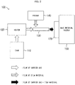
- Fig. 2 is a view schematically illustrating the cold spray device 100.
- the cold spray device 100 includes a tank 110, a heater 120, a spray nozzle 130, a feeder 140, a base material holder 150, and a control device (not illustrated).
- the tank 110 stores therein a carrier gas.
- the carrier gas is supplied from the tank 110 to the heater 120.
- the carrier gas include nitrogen, helium, air, and a mixed gas of nitrogen, helium, and air.
- a pressure of the carrier gas is adjusted so that the pressure of the carrier gas at the exit of the tank 110 is, for example, not less than 70 PSI and not more than 150 PSI (not less than approximately 0.48 Mpa and not more than approximately 1.03 Mpa). Note, however, that the pressure of the carrier gas at the exit of the tank 110 does not necessarily need to fall within the above range, and such pressure is appropriately adjusted in accordance with, for example, material(s) and/or a size of solid phase particles, or material(s) of a base material.
- the heater 120 heats the carrier gas which has been supplied from the tank 110. More specifically, the carrier gas is heated to a temperature that is lower than a melting point of the solid phase particles which are supplied from the feeder 140 to the spray nozzle 130. For example, the carrier gas is heated so that the temperature of the carrier gas at an exit of the heater 120 falls within the range of not less than 50°C and not more than 500°C. Note, however, that a heating temperature of the carrier gas at the exit of the heater 120 does not necessarily need to fall within the above range, and is appropriately adjusted in accordance with, for example, the material(s) and/or the size of the solid phase particles, or the material(s) of the base material.
- the carrier gas is heated by the heater 120 and is then supplied to the spray nozzle 130.
- the spray nozzle 130 (i) accelerates a speed of the carrier gas which has been heated by the heater 120 so that the speed falls within the range of not less than 300 m/s and not more than 1200 m/s, and then (ii) sprays the carrier gas therethrough onto a base material 170.
- the speed of the carrier gas does not necessarily need to fall within the above range, and is appropriately adjusted in accordance with, for example, the material(s) and/or the size of the solid phase particles, or the material(s) of the base material.
- the feeder 140 supplies the solid phase particles to the flow of the carrier gas whose speed is accelerated by the spray nozzle 130.
- the solid phase particles which are supplied from the feeder 140 have a particle size of, for example, not less than 1 ⁇ m and not more than 50 ⁇ m. Together with the carrier gas, the solid phase particles which have been supplied from the feeder 140 are sprayed through the spray nozzle 130 onto the base material 170.
- the base material holder 150 fixes the base material 170. Onto the base material 170 which has been fixed by the base material holder 150, the carrier gas and the solid phase particles are sprayed through the spray nozzle 130. A distance between a surface of the base material 170 and a tip of the spray nozzle 130 is adjusted so that the distance falls within the range of, for example, not less than 1 mm and not more than 30 mm. In a case where the distance between the surface of the base material 170 and the tip of the spray nozzle 130 is less than 1 mm, a spraying speed at which the solid phase particles are sprayed is decreased. This is because the carrier gas sprayed from the spray nozzle 130 flows back into the spray nozzle 130.
- a pressure generated when the carrier gas flows back can cause a member (e.g., a hose) connected to the spray nozzle 130 to be detached from the spray nozzle 130.
- a member e.g., a hose
- efficiency in film formation is decreased. This is because it becomes more difficult for the carrier gas and the solid phase particles which have been sprayed from the spray nozzle 130 to reach the base material 170.
- the distance between the surface of the base material 170 and the tip of the spray nozzle 130 does not necessarily need to fall within the above range, and is therefore appropriately adjusted in accordance with, for example, the material(s) and/or the size of the solid phase particles, or the material(s) of the base material.
- the control device controls the cold spray device 100 in accordance with information stored therein in advance and/or an input by an operator. More specifically, the control device controls, for example, (i) the pressure of the carrier gas which is supplied from the tank 110 to the heater 120, (ii) the temperature of the carrier gas which is heated by the heater 120, (iii) a kind and an amount of the solid phase particles which are supplied from the feeder 140, and (iv) the distance between the surface of the base material 170 and the spray nozzle 130.
- the cold spray device 100 may use well-known solid phase particles in order to perform the cold spraying.
- a material such as nickel powder, tin powder, or a mixed material of tin powder and zinc powder can be used as solid phase particles.
- the use of the cold spray device 100 allows enjoying advantages of cold spraying.
- the cold spraying brings about, for example, the following advantages: (1) prevention of oxidization of a film, (2) prevention of a change in quality of a film by heat, (3) formation of a dense film, (4) prevention of generation of fumes, (5) minimum masking, (6) film formation achieved by a simple device, and (7) formation of a thick metal film achieved in a short period of time.
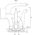
- Fig. 1 is a side view schematically illustrating the solid phase particle collection system 40 in accordance with an embodiment of the present invention.
- the solid phase particle collection system 40 is a system for collecting flying solid phase particles, which are not involved in the film formation on the base material 170, in the cold spray device 100 (solid phase particle deposition device).
- the solid phase particle collection system 40 includes a jig 10 (guide member) and a solid phase particle collection device 25.
- the solid phase particle collection device 25 includes an attachment 1 and a collection section 20.
- the attachment 1 is constituted by an engagement part 2 and an opening part 3.
- the engagement part 2 and the opening part 3 may be provided integrally. In a case where the engagement part 2 and the opening part 3 are provided integrally, no clear boundary is present between the engagement part 2 and the opening part 3.
- a connection between two different parts that have different functions can be considered to be a connection between the engagement part 2 and the opening part 3.
- the engagement part 2 and the opening part 3 may be provided as separate members and connected to each other. In a case where the engagement part 2 and the opening part 3 are provided as separate members, the engagement part 2 and the opening part 3 may be detached by any method.
- the opening part 3 has a hole corresponding to the outer shape of the engagement part 2 so that the engagement part 2 is fitted into the hole.
- the engagement part 2 is engaged with the spray nozzle 130.
- the engagement part 2 may be engaged with the spray nozzle 130 by any method.
- the engagement part 2 is engaged with the spray nozzle 130 by a method such as screwing, fitting, or bolting.
- the opening part 3 has one or more openings.
- the opening part 3 has two openings 3a and 3b.
- the openings 3a and 3b each have any shape that enables the openings 3a and 3b to be connected to a hose 22 (described later).
- the opening 3a is located above a jig 10a (described later)
- the opening 3b is located above a jig 10b (described later).
- the openings 3a and 3b are preferably positioned near the tip of the spray nozzle 130. Being positioned near the tip means that opening centers of the openings 3a and 3b are positioned at respectively corresponding positions that are not less than 5 mm and not more than 30 mm away from respectively corresponding side surfaces of the spray nozzle 130 in a lateral direction and that are at a height of not less than 5 mm and not more than 20 mm above the base material 170. This makes it possible to enhance the efficiency in collecting the solid phase particles 30b.
- the lateral direction refers to a direction that is parallel to a main surface of the base material 170 on which a film is to be formed.
- the opening centers refer to respectively corresponding centers of circles in a case where the openings 3a and 3b are circular, and refer to respectively corresponding intersections of diagonal lines in a case where the openings 3a and 3b are square or rectangular.
- the collection section 20 includes a dust collector 21 and a hose 22.
- the dust collector 21 collects, via the openings 3a and 3b, the solid phase particles 30b that are sprayed through the spray nozzle 130 onto the base material 170 and are not involved in the film formation on the base material 170.
- the dust collector 21 preferably has the ability to collect dust at an airflow rate that is equal to or higher than a predetermined airflow rate. In a case where the dust collector 21 has the ability to collect dust at an airflow rate that is equal to or higher than a predetermined airflow rate, it is possible for the dust collector 21 to enhance the efficiency in collecting the solid phase particles 30b. In a case where the dust collector 21 has the ability to collect dust at an airflow rate that is lower than the predetermined airflow rate, the efficiency in collecting the solid phase particles 30b decreases.
- the predetermined airflow rate is determined according to, for example, the shape of the openings 3a and 3b, the distance between the openings 3a and 3b and the base material 170, and/or the pressure of the carrier gas.
- the dust collector 21 may be realized by any other configuration (such as a cyclone or static electricity) capable of collecting the solid phase particles 30b.
- the hose 22 has a first end that is connected to the openings 3a and 3b, and has a second end that differs from the first end and that is connected to the dust collector 21.
- the hose 22 is connected to the openings 3a and 3b and/or the dust collector 21 by a method such as screwing or fitting.
- the hose 22 may be of any material and/or shape.
- the jig 10 is fixed to the base material 170. Alternatively, the jig 10 is detachably provided on the base material 170.
- the jig 10 includes one or more jigs.
- the jig 10 rectifies the flow of the carrier gas sprayed through the spray nozzle 130 and guides the solid phase particles 30b toward the openings 3a and 3b.
- the jig 10 preferably extends along a direction in which the spray nozzle 130 moves.
- a material of the jig 10 is not limited, provided that the material exhibits the above functions.
- the jig 10 includes a jig 10a and a jig 10b.
- the jig 10a and the jig 10b are provided on the base material 170 and guide the solid phase particles 30b toward the openings 3a and 3b, respectively.
- the jigs 10a and 10b are referred to simply as jigs 10.
- the solid phase particles 30a are solid phase particles that have been involved in the film formation on the base material 170.
- the solid phase particles 30b are solid phase particles that have not been involved in the film formation on the base material 170.
- Fig. 3 shows a photograph illustrating an example of the jig 10 in accordance with an embodiment of the present invention.
- the jig 10a and the jig 10b are provided on the base material 170.
- the jig 10a and the jig 10b extend along the direction in which the spray nozzle 130 (not illustrated) moves.
- the jig 10a has a surface 11a perpendicular to the base material 170 and has a surface 12a formed in the shape of an arc.
- the jig 10b has a surface 11b perpendicular to the base material 170 and has a surface 12b formed in the shape of an arc.
- the surfaces 11a and 11b are provided on a spray nozzle 130 side.
- Fig. 4 shows a photograph illustrating another example of the jig 10 in accordance with an embodiment of the present invention.
- the surface 12a and the surface 12b are provided on the spray nozzle 130 side.
- Figs. 3 and 4 merely illustrate examples, and the jig 10 may be configured in other shapes.
- Other examples of the shape of a cross section of the jig 10 include a square shape, a rectangular shape, a triangular shape, and a circular shape.
- FIG. 5 to 9 a state in which the solid phase particles 30b are collected will be described with reference to Figs. 5 to 9 .
- the attachment 1 and the collection section 20 are not illustrated for ease of viewing.
- the arrows illustrated in Figs. 7 to 9 indicate directions in which the solid phase particles 30b are collected.
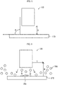
- Fig. 5 is a view schematically illustrating a positional relationship between the spray nozzle 130 and the base material 170.
- D indicates a distance between the spray nozzle 130 and the base material 170.
- D is set to, for example, not less than 5 mm and not more than 15 mm.
- ⁇ indicates an angle of the spray nozzle 130 with respect to the base material 170.
- ⁇ is set to 90 degrees.
- ⁇ is preferably not less than 75 degrees and not more than 90 degrees.
- Fig. 6 is a view illustrating a state in which the solid phase particles 30b fly from the spray nozzle 130. Normally, in the cold spray method, the solid phase particles 30b account for approximately 97% of all of the solid phase particles, and the remaining solid phase particles (solid phase particles 30a) are involved in the film formation on the base material 170.
- a carrier gas passage inside the spray nozzle 130 is such that fluid energy becomes lower toward an end portion of the carrier gas passage in a cross section of the spray nozzle 130 perpendicular to a direction in which the carrier gas passes.
- the solid phase particles that pass through the end portion of the carrier gas passage are likely to fly into the air without being involved in the film formation.
- Fig. 6 illustrates such a state.
- the solid phase particles 30b move in the vicinity of the base material 170 under the influence of the carrier gas.
- the solid phase particles 30b exhibit a high particle distribution in a region having a height of not more than 20 mm above the base material 170 (in a region such that H in Fig. 6 is not more than 20 mm).
- the region in which the solid phase particles 30b exhibit a high particle distribution is referred to as a "high distribution region”.
- Fig. 7 shows a view illustrating a state in which the solid phase particles 30b are collected.
- the openings 3a and 3b of the opening part 3 are preferably provided in the high distribution region. Positioning the openings 3a and 3b in the high distribution region enables enhancement of the efficiency in collecting the solid phase particles 30b.
- Fig. 8 shows a view illustrating a state in which the jigs 10a and 10b are provided on the base material 170.
- the jig 10a is located below the opening 3a, and the jig 10b is located below the opening 3b.
- the jigs 10a and 10b rectify the flow of the carrier gas sprayed through the spray nozzle 130 and guide the solid phase particles 30b toward the openings 3a and 3b. This makes it possible to further enhance the efficiency in collecting the solid phase particles 30b.
- Fig. 9 illustrates an example of the shape of the jig 10.
- a cross section of the jig 10a is in the shape of a circle
- a cross section of the jig 10b is in the shape of a square.
- the shape of the cross section of the jig 10 may be, for example, a square shape, a rectangular shape, a triangular shape, a circular shape, or an arc shape.
- the size of the jig 10 only need be a size such that the jig 10 does not come into contact with the tip of the spray nozzle 130.
- the jig 10 may be only one jig. However, the jig 10 preferably has two jigs 10a and 10b that extend along the direction in which the spray nozzle 130 moves. This makes it possible to further enhance the efficiency in collecting the solid phase particles 30b.
- the attachment 1 was used in all of the cases (1) to (3).
- Opening center of the opening part 3 is a first opening center of the opening part 3
- the above cases (2) and (3) are cases where the attachment 1 and the jig 10 were used. In these cases, it was found that the efficiency in collecting the solid phase particles further enhanced and was about three times that of the above case (1).
- the solid phase particle collection system 40, the solid phase particle collection device 25, and the attachment 1 in accordance with an embodiment of the present invention enable significant enhancement of the efficiency in collecting solid phase particles over the conventional techniques.
- This effect is greater in a case where the cross section of the carrier gas passage inside the spray nozzle 130 is rectangular.
- the attachment 1 in accordance with an embodiment of the present invention is set to the spray nozzle 130.
- the solid phase particle collection system 40, the solid phase particle collection device 25, and the attachment 1 in accordance with an embodiment of the present invention can be effectively used regardless of the shape of the cross section of the carrier gas passage inside the spray nozzle 130. Therefore, the solid phase particle collection system 40, the solid phase particle collection device 25, and the attachment 1 in accordance with an embodiment of the present invention can also solve the conventional problem that the flying of solid phase particles hinders mass production of products.
- Nickel is used as the solid phase particles in the above cases (1) to (3), but, as a matter of course, a similar effect can be expected even when other solid phase particles are used.
- An attachment in accordance with Aspect 1 of the present invention includes: an engagement part to be engaged with a spray nozzle of a solid phase particle deposition device; and an opening part connected to the engagement part and having at least one opening to be connected to a collection section that is configured to collect solid phase particles which are sprayed through the spray nozzle onto a base material and are not involved in formation of a film on the base material.
- the above configuration makes it possible to efficiently collect flying solid phase particles even in a case where a spray nozzle of a solid phase particle deposition device is in motion.
- the attachment in accordance with Aspect 1 above may be configured such that the opening part is integral with the engagement part.
- the above configuration facilitates the production of the attachment and eliminates the need to manually connect the engagement part and the opening part to each other.
- the attachment in accordance with Aspect 1 or 2 of the present invention may be configured such that the at least one opening includes two openings, and the two openings are provided such that the engagement part is interposed between the two openings.
- the above configuration allows flying solid phase particles to be collected from directions which extend with the engagement part interposed therebetween, and thus makes it possible to enhance the efficiency in collecting solid phase particles.
- a solid phase particle collection device in accordance with Aspect 4 of the present invention includes: an attachment set to a spray nozzle of the solid phase particle deposition device and having an opening; a collection section connected to the opening and configured to collect, via the opening, solid phase particles which are sprayed through the spray nozzle onto a base material and are not involved in formation of a film on the base material; and a guide member provided on the base material and configured to guide the solid phase particles toward the opening.
- a solid phase particle collection system in accordance with Aspect 5 of the present invention includes: an attachment set to a spray nozzle of a solid phase particle deposition device and having an opening; a collection section connected to the opening and configured to collect, via the opening, solid phase particles which are sprayed through the spray nozzle onto a base material and are not involved in formation of a film on the base material; and a guide member provided on the base material and configured to guide the solid phase particles toward the opening.
- the solid phase particle collection system in accordance with Aspect 5 of the present invention may be configured such that the guide member extends along a direction in which the spray nozzle moves.
- the above configuration makes it possible to maintain the efficiency in collecting the solid phase particles even in a case where the spray nozzle is in motion.
- the solid phase particle collection system in accordance with Aspect 5 or 6 of the present invention may be configured such that the guide member is located below the opening.
- the solid phase particle collection system in accordance with Aspect 7 of the present invention may be configured such that an opening center of the opening is positioned at a position that is not less than 5 mm and not more than 30 mm away from a side surface of the spray nozzle in a lateral direction and that is at a height of not less than 5 mm and not more than 20 mm above the base material.
- the solid phase particle collection system in accordance with any one of Aspects 5 to 8 of the present invention may be configured such that the guide member is in a shape of a rectangle, a square, a triangle, a circle, or an arc in cross section perpendicular to a direction in which the spray nozzle moves.
- the above configuration makes it possible to efficiently collect flying solid phase particles.
- the present invention is not limited to the embodiments, but can be altered by a skilled person in the art within the scope of the claims.
- the present invention also encompasses, in its technical scope, any embodiment derived by combining technical means disclosed in differing embodiments.
Landscapes
- Chemical & Material Sciences (AREA)
- Chemical Kinetics & Catalysis (AREA)
- Engineering & Computer Science (AREA)
- Materials Engineering (AREA)
- Mechanical Engineering (AREA)
- Metallurgy (AREA)
- Organic Chemistry (AREA)
- Other Surface Treatments For Metallic Materials (AREA)
- Transplanting Machines (AREA)
Abstract
Description
- The present invention relates to an attachment, a solid phase particle collection device, and a solid phase particle collection system each of which is used in a solid phase particle deposition device.
- A solid phase particle deposition method is known as a technique of spraying solid phase particles (powder) onto a base material to form a film on the base material. The solid phase particle deposition method includes, for example, a cold spray method.
- The cold spray method is a technique for accelerating powder with high-pressure gas to form a film on a base material. After collision with the base material, the powder that has not form a film can have the following adverse effects: (1) adhesion to the periphery of the base material; (2) adhesion to an inner wall of a chamber; (3) adhesion to surrounding parts and the like; and/or (4) flying to the outside due to opening and closing of the chamber. A method for collecting flying powder during film formation is disclosed in, for example, Patent Literature 1.
-
Japanese Patent Application Publication Tokukai No. 2003-119673 - Patent Literature 1 discloses a suction member that sucks an aerosol that is not involved in the formation of a structure after the aerosol has collided with a base material.
- However, in Patent Literature 1, a spray nozzle is not in motion, and a suction cylinder is not attached to the spray nozzle (see
Fig. 3 ). Thus, the technique of Patent Literature 1 has a problem that flying powder is not collected from the suction cylinder in a case where the spray nozzle is in motion. - An aspect of the present invention has been made in view of the above-described problem, and an object thereof is to provide an attachment, a solid phase particle collection device, and a solid phase particle collection system each of which is capable of efficiently collecting flying solid phase particles even in a case where a spray nozzle of a solid phase particle deposition device is in motion.
- In order to solve the above-described problem, an attachment in accordance with an aspect of the present disclosure includes: an engagement part to be engaged with a spray nozzle of a solid phase particle deposition device; and an opening part connected to the engagement part and having at least one opening to be connected to a collection section that is configured to collect solid phase particles which are sprayed through the spray nozzle onto a base material and are not involved in formation of a film on the base material.
- In order to solve the above-described problem, a solid phase particle collection device in accordance with an aspect of the present disclosure is a solid phase particle collection device for use in a solid phase particle deposition device, including: an attachment set to a spray nozzle of the solid phase particle deposition device and having an opening; and a collection section connected to the opening and configured to collect, via the opening, solid phase particles which are sprayed through the spray nozzle onto a base material and are not involved in formation of a film on the base material.
- In order to solve the above-described problem, a solid phase particle collection system in accordance with an aspect of the present disclosure includes: an attachment set to a spray nozzle of a solid phase particle deposition device and having an opening; a collection section connected to the opening and configured to collect, via the opening, solid phase particles which are sprayed through the spray nozzle onto a base material and are not involved in formation of a film on the base material; and a guide member provided on the base material and configured to guide the solid phase particles toward the opening.
- According to an aspect of the present disclosure, it is possible to efficiently collect flying solid phase particles even in a case where a spray nozzle of a solid phase particle deposition device is in motion.
-
- Fig. 1
- shows a side view schematically illustrating a solid phase particle collection system in accordance with an embodiment of the present invention.
- Fig. 2
- shows a view schematically illustrating a cold spray device in accordance with an embodiment of the present invention.
- Fig. 3
- shows a photograph illustrating an example of a jig in accordance with an embodiment of the present invention.
- Fig. 4
- shows a photograph illustrating another example of the jig in accordance with an embodiment of the present invention.
- Fig. 5
- shows a view schematically illustrating a positional relationship between a spray nozzle and a base material.
- Fig. 6
- shows a view illustrating a state in which solid phase particles fly from the spray nozzle.
- Fig. 7
- shows a view illustrating a state in which the solid phase particles are collected.
- Fig. 8
- shows a view illustrating a state in which the jig is provided on the base material, in accordance with an embodiment of the present invention.
- Fig. 9
- shows a view illustrating an example of the shape of the jig in accordance with an embodiment of the present invention.
- Embodiments are described below with reference to the drawings. In the following description, identical components and identical constituent elements are given respective identical reference signs. Such components and constituent elements are also identical in name and function. Thus, a specific description of those components and constituent elements is not repeated.
- An embodiment of the present invention can be applied to a solid phase particle deposition device. The solid phase particle deposition device includes, for example, cold spraying or aerosol deposition. The description of an embodiment of the present invention takes cold spraying as an example.
- In recent years, a film forming method, that is called "cold spraying", has been used. The cold spraying is a method for (i) causing a carrier gas whose temperature is lower than a melting point or a softening temperature of a film material (solid phase particles) to flow at a high speed, (ii) introducing the solid phase particles into the flow of the carrier gas so as to increase the speed of the carrier gas into which the solid phase particles have been introduced, and (iii) causing the solid phase particles to collide with, for example, a base material at a high speed while the solid phase particles are in a solid phase so as to form a film.
- A principle of film formation by the cold spraying is understood as below.
- A collision speed of not less than a certain critical value is required for solid phase particles to adhere to and accumulate on a base material so as to form a film on the base material. Such a collision speed is referred to as a critical speed. In a case where the solid phase particles collide with the base material at a speed that is lower than the critical speed, the base material is worn, so that small crater-shaped cavities are merely formed in the base material. The critical speed is changed in accordance with, for example, a material, a size, a shape, a temperature, and/or an oxygen content of the solid phase particles, or a material of the base material.
- In a case where the solid phase particles collide with the base material at a speed that is not less than the critical speed, plastic deformation caused by a great shearing force occurs near an interface between the solid phase particles and the base material (or the film which has already been formed). The plastic deformation and generation of a great shock wave in a solid due to the collision cause an increase in temperature near the interface, and in this process, solid phase bonding occurs (i) between the solid phase particles and the base material and (ii) between the solid phase particles and the film (or the solid phase particles which have already adhered to the base material).
-
Fig. 2 is a view schematically illustrating thecold spray device 100. As illustrated inFig. 2 , thecold spray device 100 includes atank 110, aheater 120, aspray nozzle 130, afeeder 140, abase material holder 150, and a control device (not illustrated). - The
tank 110 stores therein a carrier gas. The carrier gas is supplied from thetank 110 to theheater 120. Examples of the carrier gas include nitrogen, helium, air, and a mixed gas of nitrogen, helium, and air. A pressure of the carrier gas is adjusted so that the pressure of the carrier gas at the exit of thetank 110 is, for example, not less than 70 PSI and not more than 150 PSI (not less than approximately 0.48 Mpa and not more than approximately 1.03 Mpa). Note, however, that the pressure of the carrier gas at the exit of thetank 110 does not necessarily need to fall within the above range, and such pressure is appropriately adjusted in accordance with, for example, material(s) and/or a size of solid phase particles, or material(s) of a base material. - The
heater 120 heats the carrier gas which has been supplied from thetank 110. More specifically, the carrier gas is heated to a temperature that is lower than a melting point of the solid phase particles which are supplied from thefeeder 140 to thespray nozzle 130. For example, the carrier gas is heated so that the temperature of the carrier gas at an exit of theheater 120 falls within the range of not less than 50°C and not more than 500°C. Note, however, that a heating temperature of the carrier gas at the exit of theheater 120 does not necessarily need to fall within the above range, and is appropriately adjusted in accordance with, for example, the material(s) and/or the size of the solid phase particles, or the material(s) of the base material. - The carrier gas is heated by the
heater 120 and is then supplied to thespray nozzle 130. - The spray nozzle 130 (i) accelerates a speed of the carrier gas which has been heated by the
heater 120 so that the speed falls within the range of not less than 300 m/s and not more than 1200 m/s, and then (ii) sprays the carrier gas therethrough onto abase material 170. Note, however, that the speed of the carrier gas does not necessarily need to fall within the above range, and is appropriately adjusted in accordance with, for example, the material(s) and/or the size of the solid phase particles, or the material(s) of the base material. - The
feeder 140 supplies the solid phase particles to the flow of the carrier gas whose speed is accelerated by thespray nozzle 130. The solid phase particles which are supplied from thefeeder 140 have a particle size of, for example, not less than 1 µm and not more than 50 µm. Together with the carrier gas, the solid phase particles which have been supplied from thefeeder 140 are sprayed through thespray nozzle 130 onto thebase material 170. - The
base material holder 150 fixes thebase material 170. Onto thebase material 170 which has been fixed by thebase material holder 150, the carrier gas and the solid phase particles are sprayed through thespray nozzle 130. A distance between a surface of thebase material 170 and a tip of thespray nozzle 130 is adjusted so that the distance falls within the range of, for example, not less than 1 mm and not more than 30 mm. In a case where the distance between the surface of thebase material 170 and the tip of thespray nozzle 130 is less than 1 mm, a spraying speed at which the solid phase particles are sprayed is decreased. This is because the carrier gas sprayed from thespray nozzle 130 flows back into thespray nozzle 130. During the flowing back, a pressure generated when the carrier gas flows back can cause a member (e.g., a hose) connected to thespray nozzle 130 to be detached from thespray nozzle 130. Note, however, that in a case where the distance between the surface of thebase material 170 and the tip of thespray nozzle 130 is more than 30 mm, efficiency in film formation is decreased. This is because it becomes more difficult for the carrier gas and the solid phase particles which have been sprayed from thespray nozzle 130 to reach thebase material 170. - Note, however, that the distance between the surface of the
base material 170 and the tip of thespray nozzle 130 does not necessarily need to fall within the above range, and is therefore appropriately adjusted in accordance with, for example, the material(s) and/or the size of the solid phase particles, or the material(s) of the base material. - The control device controls the
cold spray device 100 in accordance with information stored therein in advance and/or an input by an operator. More specifically, the control device controls, for example, (i) the pressure of the carrier gas which is supplied from thetank 110 to theheater 120, (ii) the temperature of the carrier gas which is heated by theheater 120, (iii) a kind and an amount of the solid phase particles which are supplied from thefeeder 140, and (iv) the distance between the surface of thebase material 170 and thespray nozzle 130. - The
cold spray device 100 may use well-known solid phase particles in order to perform the cold spraying. For example, a material such as nickel powder, tin powder, or a mixed material of tin powder and zinc powder can be used as solid phase particles. - The use of the
cold spray device 100 allows enjoying advantages of cold spraying. The cold spraying brings about, for example, the following advantages: (1) prevention of oxidization of a film, (2) prevention of a change in quality of a film by heat, (3) formation of a dense film, (4) prevention of generation of fumes, (5) minimum masking, (6) film formation achieved by a simple device, and (7) formation of a thick metal film achieved in a short period of time. - The following will describe a solid phase
particle collection system 40 in accordance with an embodiment of the present invention with reference toFig. 1. Fig. 1 is a side view schematically illustrating the solid phaseparticle collection system 40 in accordance with an embodiment of the present invention. - The solid phase
particle collection system 40 is a system for collecting flying solid phase particles, which are not involved in the film formation on thebase material 170, in the cold spray device 100 (solid phase particle deposition device). The solid phaseparticle collection system 40 includes a jig 10 (guide member) and a solid phaseparticle collection device 25. The solid phaseparticle collection device 25 includes an attachment 1 and acollection section 20. - The attachment 1 is constituted by an
engagement part 2 and anopening part 3. Theengagement part 2 and theopening part 3 may be provided integrally. In a case where theengagement part 2 and theopening part 3 are provided integrally, no clear boundary is present between theengagement part 2 and theopening part 3. However, in the attachment 1, a connection between two different parts that have different functions can be considered to be a connection between theengagement part 2 and theopening part 3. - The
engagement part 2 and theopening part 3 may be provided as separate members and connected to each other. In a case where theengagement part 2 and theopening part 3 are provided as separate members, theengagement part 2 and theopening part 3 may be detached by any method. For example, theopening part 3 has a hole corresponding to the outer shape of theengagement part 2 so that theengagement part 2 is fitted into the hole. - The
engagement part 2 is engaged with thespray nozzle 130. Theengagement part 2 may be engaged with thespray nozzle 130 by any method. For example, theengagement part 2 is engaged with thespray nozzle 130 by a method such as screwing, fitting, or bolting. - The
opening part 3 has one or more openings. InFig. 1 , theopening part 3 has twoopenings openings openings opening 3a is located above ajig 10a (described later), and theopening 3b is located above ajig 10b (described later). - The
openings spray nozzle 130. Being positioned near the tip means that opening centers of theopenings spray nozzle 130 in a lateral direction and that are at a height of not less than 5 mm and not more than 20 mm above thebase material 170. This makes it possible to enhance the efficiency in collecting thesolid phase particles 30b. The lateral direction refers to a direction that is parallel to a main surface of thebase material 170 on which a film is to be formed. The opening centers refer to respectively corresponding centers of circles in a case where theopenings openings - The
collection section 20 includes adust collector 21 and ahose 22. Thedust collector 21 collects, via theopenings solid phase particles 30b that are sprayed through thespray nozzle 130 onto thebase material 170 and are not involved in the film formation on thebase material 170. - The
dust collector 21 preferably has the ability to collect dust at an airflow rate that is equal to or higher than a predetermined airflow rate. In a case where thedust collector 21 has the ability to collect dust at an airflow rate that is equal to or higher than a predetermined airflow rate, it is possible for thedust collector 21 to enhance the efficiency in collecting thesolid phase particles 30b. In a case where thedust collector 21 has the ability to collect dust at an airflow rate that is lower than the predetermined airflow rate, the efficiency in collecting thesolid phase particles 30b decreases. The predetermined airflow rate is determined according to, for example, the shape of theopenings openings base material 170, and/or the pressure of the carrier gas. Thedust collector 21 may be realized by any other configuration (such as a cyclone or static electricity) capable of collecting thesolid phase particles 30b. - The
hose 22 has a first end that is connected to theopenings dust collector 21. Thehose 22 is connected to theopenings dust collector 21 by a method such as screwing or fitting. Thehose 22 may be of any material and/or shape. - The
jig 10 is fixed to thebase material 170. Alternatively, thejig 10 is detachably provided on thebase material 170. Thejig 10 includes one or more jigs. Thejig 10 rectifies the flow of the carrier gas sprayed through thespray nozzle 130 and guides thesolid phase particles 30b toward theopenings jig 10 preferably extends along a direction in which thespray nozzle 130 moves. A material of thejig 10 is not limited, provided that the material exhibits the above functions. - In the example illustrated in
Fig. 1 , thejig 10 includes ajig 10a and ajig 10b. Thejig 10a and thejig 10b are provided on thebase material 170 and guide thesolid phase particles 30b toward theopenings jigs jigs - The
solid phase particles 30a are solid phase particles that have been involved in the film formation on thebase material 170. Thesolid phase particles 30b are solid phase particles that have not been involved in the film formation on thebase material 170. -
Fig. 3 shows a photograph illustrating an example of thejig 10 in accordance with an embodiment of the present invention. As illustrated inFig. 3 , thejig 10a and thejig 10b are provided on thebase material 170. Thejig 10a and thejig 10b extend along the direction in which the spray nozzle 130 (not illustrated) moves. - The
jig 10a has asurface 11a perpendicular to thebase material 170 and has asurface 12a formed in the shape of an arc. Thejig 10b has asurface 11b perpendicular to thebase material 170 and has asurface 12b formed in the shape of an arc. InFig. 3 , thesurfaces spray nozzle 130 side. -
Fig. 4 shows a photograph illustrating another example of thejig 10 in accordance with an embodiment of the present invention. InFig. 4 , thesurface 12a and thesurface 12b are provided on thespray nozzle 130 side. -
Figs. 3 and 4 merely illustrate examples, and thejig 10 may be configured in other shapes. Other examples of the shape of a cross section of thejig 10 include a square shape, a rectangular shape, a triangular shape, and a circular shape. - Next, a state in which the
solid phase particles 30b are collected will be described with reference toFigs. 5 to 9 . InFigs. 5 to 9 , the attachment 1 and thecollection section 20 are not illustrated for ease of viewing. The arrows illustrated inFigs. 7 to 9 indicate directions in which thesolid phase particles 30b are collected. -
Fig. 5 is a view schematically illustrating a positional relationship between thespray nozzle 130 and thebase material 170. D indicates a distance between thespray nozzle 130 and thebase material 170. D is set to, for example, not less than 5 mm and not more than 15 mm. θ indicates an angle of thespray nozzle 130 with respect to thebase material 170. InFig. 5 , θ is set to 90 degrees. Considering the film formation efficiency, θ is preferably not less than 75 degrees and not more than 90 degrees. -
Fig. 6 is a view illustrating a state in which thesolid phase particles 30b fly from thespray nozzle 130. Normally, in the cold spray method, thesolid phase particles 30b account for approximately 97% of all of the solid phase particles, and the remaining solid phase particles (solid phase particles 30a) are involved in the film formation on thebase material 170. - A carrier gas passage inside the
spray nozzle 130 is such that fluid energy becomes lower toward an end portion of the carrier gas passage in a cross section of thespray nozzle 130 perpendicular to a direction in which the carrier gas passes. Thus, the solid phase particles that pass through the end portion of the carrier gas passage are likely to fly into the air without being involved in the film formation.Fig. 6 illustrates such a state. - The
solid phase particles 30b move in the vicinity of thebase material 170 under the influence of the carrier gas. In a region extending not less than 10 mm from the side surface of thespray nozzle 130 in the lateral direction (in a region such that L inFig. 6 is not less than 10 mm), thesolid phase particles 30b exhibit a high particle distribution in a region having a height of not more than 20 mm above the base material 170 (in a region such that H inFig. 6 is not more than 20 mm). Hereinafter, the region in which thesolid phase particles 30b exhibit a high particle distribution is referred to as a "high distribution region". -
Fig. 7 shows a view illustrating a state in which thesolid phase particles 30b are collected. Although not illustrated inFig. 7 , theopenings opening part 3 are preferably provided in the high distribution region. Positioning theopenings solid phase particles 30b. -
Fig. 8 shows a view illustrating a state in which thejigs base material 170. Thejig 10a is located below theopening 3a, and thejig 10b is located below theopening 3b. Thejigs spray nozzle 130 and guide thesolid phase particles 30b toward theopenings solid phase particles 30b. -
Fig. 9 illustrates an example of the shape of thejig 10. InFig. 9 , a cross section of thejig 10a is in the shape of a circle, and a cross section of thejig 10b is in the shape of a square. These are merely examples, and the shape of the cross section of thejig 10 may be, for example, a square shape, a rectangular shape, a triangular shape, a circular shape, or an arc shape. The size of thejig 10 only need be a size such that thejig 10 does not come into contact with the tip of thespray nozzle 130. - The
jig 10 may be only one jig. However, thejig 10 preferably has twojigs spray nozzle 130 moves. This makes it possible to further enhance the efficiency in collecting thesolid phase particles 30b. - The following will show the efficiency in collecting the
solid phase particles 30b which efficiency was calculated for each of the following cases (1) to (3): - (1) Case with no use of the jig 10: 9.2%
- (2) Case illustrated in
Fig. 3 : 26.8% - (3) Case illustrated in
Fig. 4 : 24.3% (R = 20 mm) - The attachment 1 was used in all of the cases (1) to (3).
- Opening center of the opening part 3:
- 10 mm away from the side surface of the
spray nozzle 130 in the lateral direction and 20 mm high above thebase material 170 - Opening radius of the opening part 3: 7.5 mm
- Number of openings of the opening part 3: two
- Positions of the two openings: the two openings were located above the
jigs engagement part 2 was interposed between the two openings. - Airflow rate of the dust collector 21: 1.5 m3/min
- Scanning speed of the spray nozzle 130: 5 mm/sec
- Collection efficiency: calculated by "(collection amount / introduction amount) × 100"
- Each of the above values is a value obtained as a result of the operation performed once each.
- Distance between the
spray nozzle 130 and the base material 170: 10 mm - Angle of the
spray nozzle 130 with respect to the base material 170: 90 degrees - Solid phase particles: nickel
- Pressure of the carrier gas: adjusted so that the pressure of the carrier gas was not less than 70 PSI and not more than 150 PSI (not less than approximately 0.48 Mpa and not more than approximately 1.03 Mpa) at an exit of the
tank 110. - Normally, in the cold spray method, approximately 97% of introduced solid phase particles become flying solid phase particles. The above case (1) is a case where only the attachment 1 was used. Even in this case, it was shown that 9.2% of the introduced solid phase particles were collected. From this result, it is found that the efficiency in collecting the solid phase particles enhances even in a case where the
spray nozzle 130 is in motion. The higher the collection efficiency, the more resources and costs can be saved. - The above cases (2) and (3) are cases where the attachment 1 and the
jig 10 were used. In these cases, it was found that the efficiency in collecting the solid phase particles further enhanced and was about three times that of the above case (1). - In the solid phase particle deposition device (cold spraying or aerosol deposition), there may be cases where the spray nozzle is in motion. Even in this case, as described above, the solid phase
particle collection system 40, the solid phaseparticle collection device 25, and the attachment 1 in accordance with an embodiment of the present invention enable significant enhancement of the efficiency in collecting solid phase particles over the conventional techniques. - This effect is greater in a case where the cross section of the carrier gas passage inside the
spray nozzle 130 is rectangular. - Specifically, in a case where the cross section of the carrier gas passage inside the
spray nozzle 130 is rectangular, fluid energy becomes lower toward the end portion of the carrier gas passage in the cross section perpendicular to the direction in which the carrier gas passes. This tends to increase solid phase particles flying into the air. - In this respect, the attachment 1 in accordance with an embodiment of the present invention is set to the
spray nozzle 130. Thus, even in a case where the cross section of the carrier gas passage inside thespray nozzle 130 is rectangular, it is possible to maintain the efficiency in collecting the solid phase particles. That is, the solid phaseparticle collection system 40, the solid phaseparticle collection device 25, and the attachment 1 in accordance with an embodiment of the present invention can be effectively used regardless of the shape of the cross section of the carrier gas passage inside thespray nozzle 130. Therefore, the solid phaseparticle collection system 40, the solid phaseparticle collection device 25, and the attachment 1 in accordance with an embodiment of the present invention can also solve the conventional problem that the flying of solid phase particles hinders mass production of products. - Nickel is used as the solid phase particles in the above cases (1) to (3), but, as a matter of course, a similar effect can be expected even when other solid phase particles are used.
- Aspects of the present invention can also be expressed as follows:
An attachment in accordance with Aspect 1 of the present invention includes: an engagement part to be engaged with a spray nozzle of a solid phase particle deposition device; and an opening part connected to the engagement part and having at least one opening to be connected to a collection section that is configured to collect solid phase particles which are sprayed through the spray nozzle onto a base material and are not involved in formation of a film on the base material. - The above configuration makes it possible to efficiently collect flying solid phase particles even in a case where a spray nozzle of a solid phase particle deposition device is in motion.
- In
Aspect 2 of the present invention, the attachment in accordance with Aspect 1 above may be configured such that the opening part is integral with the engagement part. - The above configuration facilitates the production of the attachment and eliminates the need to manually connect the engagement part and the opening part to each other.
- In
Aspect 3 of the present invention, the attachment in accordance withAspect 1 or 2 of the present invention may be configured such that the at least one opening includes two openings, and the two openings are provided such that the engagement part is interposed between the two openings. - The above configuration allows flying solid phase particles to be collected from directions which extend with the engagement part interposed therebetween, and thus makes it possible to enhance the efficiency in collecting solid phase particles.
- A solid phase particle collection device in accordance with Aspect 4 of the present invention includes: an attachment set to a spray nozzle of the solid phase particle deposition device and having an opening; a collection section connected to the opening and configured to collect, via the opening, solid phase particles which are sprayed through the spray nozzle onto a base material and are not involved in formation of a film on the base material; and a guide member provided on the base material and configured to guide the solid phase particles toward the opening.
- The above configuration brings about the same effect as the effect brought about by the attachment.
- A solid phase particle collection system in accordance with Aspect 5 of the present invention includes: an attachment set to a spray nozzle of a solid phase particle deposition device and having an opening; a collection section connected to the opening and configured to collect, via the opening, solid phase particles which are sprayed through the spray nozzle onto a base material and are not involved in formation of a film on the base material; and a guide member provided on the base material and configured to guide the solid phase particles toward the opening.
- The above configuration brings about the same effect as the effects brought about by the attachment and the solid phase particle collection device.
- In Aspect 6 of the present invention, the solid phase particle collection system in accordance with Aspect 5 of the present invention may be configured such that the guide member extends along a direction in which the spray nozzle moves.
- The above configuration makes it possible to maintain the efficiency in collecting the solid phase particles even in a case where the spray nozzle is in motion.
- In Aspect 7 of the present invention, the solid phase particle collection system in accordance with Aspect 5 or 6 of the present invention may be configured such that the guide member is located below the opening.
- The above configuration makes it possible to further enhance the efficiency in collecting the solid phase particles.
- In Aspect 8 of the present invention, the solid phase particle collection system in accordance with Aspect 7 of the present invention may be configured such that an opening center of the opening is positioned at a position that is not less than 5 mm and not more than 30 mm away from a side surface of the spray nozzle in a lateral direction and that is at a height of not less than 5 mm and not more than 20 mm above the base material.
- According to the above configuration, enhancement of the efficiency in collecting the solid phase particles can be expected.
- In Aspect 9 of the present invention, the solid phase particle collection system in accordance with any one of Aspects 5 to 8 of the present invention may be configured such that the guide member is in a shape of a rectangle, a square, a triangle, a circle, or an arc in cross section perpendicular to a direction in which the spray nozzle moves.
- The above configuration makes it possible to efficiently collect flying solid phase particles.
- The present invention is not limited to the embodiments, but can be altered by a skilled person in the art within the scope of the claims. The present invention also encompasses, in its technical scope, any embodiment derived by combining technical means disclosed in differing embodiments.
-
- 1
- attachment
- 2
- engagement part
- 3
- opening part
- 3a, 3b
- opening
- 30a, 30b
- solid phase particle
- 10, 10a, 10b
- jig (guide member)
- 20
- collection section
- 21
- dust collector
- 22
- hose
- 25
- solid phase particle collection device
- 40
- solid phase particle collection system
- 100
- cold spray device
- 110
- tank
- 120
- heater
- 130
- spray nozzle
- 140
- feeder
- 150
- base material holder
- 170
- base material
Claims (9)
- An attachment comprising:- an engagement part to be engaged with a spray nozzle of a solid phase particle deposition device; and- an opening part connected to the engagement part and having at least one opening to be connected to a collection section that is configured to collect solid phase particles which are sprayed through the spray nozzle onto a base material and are not involved in formation of a film on the base material.
- The attachment according to claim 1, wherein the opening part is integral with the engagement part.
- The attachment according to claim 1 or 2, wherein the at least one opening includes two openings, and the two openings are provided such that the engagement part is interposed between the two openings.
- A solid phase particle collection device for use in a solid phase particle deposition device, comprising:- an attachment set to a spray nozzle of the solid phase particle deposition device and having an opening; and- a collection section connected to the opening and configured to collect, via the opening, solid phase particles which are sprayed through the spray nozzle onto a base material and are not involved in formation of a film on the base material.
- A solid phase particle collection system, comprising:- an attachment set to a spray nozzle of a solid phase particle deposition device and having an opening;- a collection section connected to the opening and configured to collect, via the opening, solid phase particles which are sprayed through the spray nozzle onto a base material and are not involved in formation of a film on the base material; and- a guide member provided on the base material and configured to guide the solid phase particles toward the opening.
- The solid phase particle collection system according to claim 5, wherein the guide member extends along a direction in which the spray nozzle moves.
- The solid phase particle collection system according to claim 5 or 6, wherein the guide member is located below the opening.
- The solid phase particle collection system according to claim 7, wherein an opening center of the opening is positioned at a position that is not less than 5 mm and not more than 30 mm away from a side surface of the spray nozzle in a lateral direction and that is at a height of not less than 5 mm and not more than 20 mm above the base material.
- The solid phase particle collection system according to any one of claims 5 to 8, wherein the guide member is in a shape of a rectangle, a square, a triangle, a circle, or an arc in cross section perpendicular to a direction in which the spray nozzle moves.
Applications Claiming Priority (2)
| Application Number | Priority Date | Filing Date | Title |
|---|---|---|---|
| JP2020030863 | 2020-02-26 | ||
| PCT/JP2021/007230 WO2021172483A1 (en) | 2020-02-26 | 2021-02-26 | Attachment, solid-phase particle collection device, and solid-phase particle collection system |
Publications (2)
| Publication Number | Publication Date |
|---|---|
| EP4112775A1 true EP4112775A1 (en) | 2023-01-04 |
| EP4112775A4 EP4112775A4 (en) | 2024-07-03 |
Family
ID=77491670
Family Applications (1)
| Application Number | Title | Priority Date | Filing Date |
|---|---|---|---|
| EP21759583.4A Pending EP4112775A4 (en) | 2020-02-26 | 2021-02-26 | ATTACHMENT, SOLID PHASE PARTICLE COLLECTION DEVICE AND SOLID PHASE PARTICLE COLLECTION SYSTEM |
Country Status (5)
| Country | Link |
|---|---|
| US (2) | US20230093928A1 (en) |
| EP (1) | EP4112775A4 (en) |
| JP (1) | JP7008166B2 (en) |
| CN (1) | CN115038812B (en) |
| WO (1) | WO2021172483A1 (en) |
Families Citing this family (1)
| Publication number | Priority date | Publication date | Assignee | Title |
|---|---|---|---|---|
| WO2024034222A1 (en) * | 2022-08-08 | 2024-02-15 | タツタ電線株式会社 | Masking jig, film formation method, and film formation device |
Family Cites Families (24)
| Publication number | Priority date | Publication date | Assignee | Title |
|---|---|---|---|---|
| US4291640A (en) * | 1977-09-09 | 1981-09-29 | The Continental Group, Inc. | Powder coating apparatus for two-piece cans |
| US4397671A (en) * | 1981-11-30 | 1983-08-09 | Ford Motor Company | Method of placing a metal oxide film on a surface of a heated glass substrate |
| US4401695A (en) * | 1982-06-01 | 1983-08-30 | Ppg Industries, Inc. | Method of and apparatus for applying powder coating reactants |
| US4705701A (en) * | 1984-11-14 | 1987-11-10 | Chronar Corporation | Conductive tin oxide methods |
| FR2626872B1 (en) * | 1988-02-09 | 1992-10-30 | Saint Gobain Vitrage | IMPROVED PROCESS AND DEVICE FOR COATING A SUBSTRATE, SUCH AS A GLASS TAPE WITH A POWDERY PRODUCT |
| US4910047A (en) * | 1988-08-11 | 1990-03-20 | Nordson Corporation | Apparatus for cleaning cartridge filters in a powder spray system |
| US4987001A (en) * | 1989-02-09 | 1991-01-22 | Nordson Corporation | Method and apparatus for coating the interior surface of hollow, tubular articles |
| US5474609A (en) * | 1992-06-30 | 1995-12-12 | Nordson Corporation | Methods and apparatus for applying powder to workpieces |
| US5356292A (en) * | 1993-12-23 | 1994-10-18 | Ho Phillip P | Dental sandblasting confiner |
| US5795626A (en) * | 1995-04-28 | 1998-08-18 | Innovative Technology Inc. | Coating or ablation applicator with a debris recovery attachment |
| JP2001079505A (en) * | 2000-07-03 | 2001-03-27 | Yokogawa Electric Corp | Suction nozzle device |
| JP2003119673A (en) | 2001-10-10 | 2003-04-23 | Unitica Fibers Ltd | Production of moisture-permeable and waterproof coated fabric |
| JP3863029B2 (en) * | 2002-02-07 | 2006-12-27 | 大成化工株式会社 | Powder coating apparatus and powder coating method on inner surface of container having shoulder |
| ATE552917T1 (en) * | 2005-08-24 | 2012-04-15 | Brother Ind Ltd | DEVICE AND METHOD FOR PRODUCING LAYERS |
| US7891315B2 (en) * | 2005-09-09 | 2011-02-22 | Sulzer Metco Ag | Powder supply system |
| HU0700639D0 (en) * | 2007-10-02 | 2007-11-28 | Hegedis Gyorgy | Method and apparatus for depositing powder onto a substrate |
| JP5308845B2 (en) | 2009-01-29 | 2013-10-09 | 株式会社日本マイクロニクス | Metal fine particle injection nozzle |
| JP5573046B2 (en) * | 2009-08-24 | 2014-08-20 | 富士通株式会社 | Film forming apparatus and film forming method |
| JP5886258B2 (en) * | 2012-10-10 | 2016-03-16 | 株式会社横河ブリッジ | Method for forming anti-rust coating on bridge |
| US9839932B2 (en) * | 2013-02-14 | 2017-12-12 | Shimadzu Corporation | Surface chemical treatment apparatus for drawing predetermined pattern by carrying out a chemical treatment |
| KR102111020B1 (en) * | 2013-05-02 | 2020-05-15 | 삼성디스플레이 주식회사 | Deposition apparatus |
| JP6181599B2 (en) * | 2014-05-02 | 2017-08-16 | 信越化学工業株式会社 | Method for producing surface-treated glass fiber film |
| KR101721898B1 (en) * | 2014-08-13 | 2017-03-31 | 주식회사 이엠따블유 | Metal powder spraying apparatus for forming metal pattern |
| WO2017026357A1 (en) * | 2015-08-10 | 2017-02-16 | シャープ株式会社 | Vapor deposition source, vapor deposition device, and method for forming film by vapor deposition |
-
2021
- 2021-02-26 US US17/801,626 patent/US20230093928A1/en not_active Abandoned
- 2021-02-26 EP EP21759583.4A patent/EP4112775A4/en active Pending
- 2021-02-26 CN CN202180013674.3A patent/CN115038812B/en active Active
- 2021-02-26 WO PCT/JP2021/007230 patent/WO2021172483A1/en not_active Ceased
- 2021-02-26 JP JP2021539084A patent/JP7008166B2/en active Active
-
2025
- 2025-06-18 US US19/242,561 patent/US20250319486A1/en active Pending
Also Published As
| Publication number | Publication date |
|---|---|
| CN115038812A (en) | 2022-09-09 |
| CN115038812B (en) | 2024-05-28 |
| JPWO2021172483A1 (en) | 2021-09-02 |
| US20230093928A1 (en) | 2023-03-30 |
| WO2021172483A1 (en) | 2021-09-02 |
| JP7008166B2 (en) | 2022-02-10 |
| US20250319486A1 (en) | 2025-10-16 |
| EP4112775A4 (en) | 2024-07-03 |
Similar Documents
| Publication | Publication Date | Title |
|---|---|---|
| EP1200200B1 (en) | Kinetic spray coating method and apparatus | |
| US20250319486A1 (en) | Solid phase particle collection system | |
| US7143967B2 (en) | Method and system for cold gas spraying | |
| US20220193782A1 (en) | Material deposition unit with multiple material focal zones, and method for build-up welding | |
| MXPA03009813A (en) | A apparatus and process for solid-state deposition and consolidation of high velocity powder particles using thermal plastic deformation. | |
| HUE028017T2 (en) | Integrated fluid jet system for etching, preparing and coating a component | |
| US6872427B2 (en) | Method for producing electrical contacts using selective melting and a low pressure kinetic spray process | |
| Ünal | Production of rapidly solidified aluminium alloy powders by gas atomisation and their applications | |
| EP4116460A1 (en) | Spray nozzle, nozzle tip part, and thermal spraying device | |
| CN107532284A (en) | Laser coating method and the equipment for performing the laser coating method | |
| US10279365B2 (en) | Thermal spray method integrating selected removal of particulates | |
| CN103302296A (en) | Titanium powder production apparatus and method | |
| KR20130132325A (en) | Method for manufacturing target with flange | |
| JP7226168B2 (en) | Composite member manufacturing method and composite member | |
| HK40072432A (en) | Attachment, solid-phase particle collection device, and solid-phase particle collection system | |
| US7959093B2 (en) | Apparatus for applying cold-spray to small diameter bores | |
| US20100260932A1 (en) | Cold spray method of applying aluminum seal strips | |
| Kosarev et al. | Recently patented facilities and applications in cold spray engineering | |
| US20050074560A1 (en) | Correcting defective kinetically sprayed surfaces | |
| JP2018508644A (en) | Thermal spraying method that integrates selective removal of particles | |
| EP1834727A2 (en) | Method of applying a coating to an article via magnetic pulse welding | |
| CN114393308A (en) | Double-wire electric arc composite laser cladding method and device | |
| JP2010137341A (en) | Blasting device | |
| US20070029370A1 (en) | Kinetic spray deposition of flux and braze alloy composite particles | |
| JPH0751871A (en) | Welding metal powder supply method and apparatus in overlay welding |
Legal Events
| Date | Code | Title | Description |
|---|---|---|---|
| STAA | Information on the status of an ep patent application or granted ep patent |
Free format text: STATUS: THE INTERNATIONAL PUBLICATION HAS BEEN MADE |
|
| PUAI | Public reference made under article 153(3) epc to a published international application that has entered the european phase |
Free format text: ORIGINAL CODE: 0009012 |
|
| STAA | Information on the status of an ep patent application or granted ep patent |
Free format text: STATUS: REQUEST FOR EXAMINATION WAS MADE |
|
| 17P | Request for examination filed |
Effective date: 20220819 |
|
| AK | Designated contracting states |
Kind code of ref document: A1 Designated state(s): AL AT BE BG CH CY CZ DE DK EE ES FI FR GB GR HR HU IE IS IT LI LT LU LV MC MK MT NL NO PL PT RO RS SE SI SK SM TR |
|
| DAV | Request for validation of the european patent (deleted) | ||
| DAX | Request for extension of the european patent (deleted) | ||
| A4 | Supplementary search report drawn up and despatched |
Effective date: 20240603 |
|
| RIC1 | Information provided on ipc code assigned before grant |
Ipc: C23C 24/04 20060101AFI20240527BHEP |