EP4112548A1 - Method for manufacturing porous silicon and secondary battery anode active material containing same - Google Patents
Method for manufacturing porous silicon and secondary battery anode active material containing same Download PDFInfo
- Publication number
- EP4112548A1 EP4112548A1 EP21774152.9A EP21774152A EP4112548A1 EP 4112548 A1 EP4112548 A1 EP 4112548A1 EP 21774152 A EP21774152 A EP 21774152A EP 4112548 A1 EP4112548 A1 EP 4112548A1
- Authority
- EP
- European Patent Office
- Prior art keywords
- porous silicon
- silicon
- secondary battery
- heat treatment
- heat
- Prior art date
- Legal status (The legal status is an assumption and is not a legal conclusion. Google has not performed a legal analysis and makes no representation as to the accuracy of the status listed.)
- Pending
Links
Images


Classifications
-
- C—CHEMISTRY; METALLURGY
- C01—INORGANIC CHEMISTRY
- C01B—NON-METALLIC ELEMENTS; COMPOUNDS THEREOF; METALLOIDS OR COMPOUNDS THEREOF NOT COVERED BY SUBCLASS C01C
- C01B33/00—Silicon; Compounds thereof
- C01B33/02—Silicon
- C01B33/021—Preparation
- C01B33/023—Preparation by reduction of silica or free silica-containing material
-
- C—CHEMISTRY; METALLURGY
- C01—INORGANIC CHEMISTRY
- C01B—NON-METALLIC ELEMENTS; COMPOUNDS THEREOF; METALLOIDS OR COMPOUNDS THEREOF NOT COVERED BY SUBCLASS C01C
- C01B33/00—Silicon; Compounds thereof
- C01B33/02—Silicon
- C01B33/021—Preparation
-
- C—CHEMISTRY; METALLURGY
- C01—INORGANIC CHEMISTRY
- C01B—NON-METALLIC ELEMENTS; COMPOUNDS THEREOF; METALLOIDS OR COMPOUNDS THEREOF NOT COVERED BY SUBCLASS C01C
- C01B33/00—Silicon; Compounds thereof
- C01B33/02—Silicon
- C01B33/037—Purification
-
- H—ELECTRICITY
- H01—ELECTRIC ELEMENTS
- H01M—PROCESSES OR MEANS, e.g. BATTERIES, FOR THE DIRECT CONVERSION OF CHEMICAL ENERGY INTO ELECTRICAL ENERGY
- H01M10/00—Secondary cells; Manufacture thereof
- H01M10/05—Accumulators with non-aqueous electrolyte
- H01M10/052—Li-accumulators
-
- H—ELECTRICITY
- H01—ELECTRIC ELEMENTS
- H01M—PROCESSES OR MEANS, e.g. BATTERIES, FOR THE DIRECT CONVERSION OF CHEMICAL ENERGY INTO ELECTRICAL ENERGY
- H01M10/00—Secondary cells; Manufacture thereof
- H01M10/05—Accumulators with non-aqueous electrolyte
- H01M10/052—Li-accumulators
- H01M10/0525—Rocking-chair batteries, i.e. batteries with lithium insertion or intercalation in both electrodes; Lithium-ion batteries
-
- H—ELECTRICITY
- H01—ELECTRIC ELEMENTS
- H01M—PROCESSES OR MEANS, e.g. BATTERIES, FOR THE DIRECT CONVERSION OF CHEMICAL ENERGY INTO ELECTRICAL ENERGY
- H01M4/00—Electrodes
- H01M4/02—Electrodes composed of, or comprising, active material
- H01M4/04—Processes of manufacture in general
- H01M4/0471—Processes of manufacture in general involving thermal treatment, e.g. firing, sintering, backing particulate active material, thermal decomposition, pyrolysis
-
- H—ELECTRICITY
- H01—ELECTRIC ELEMENTS
- H01M—PROCESSES OR MEANS, e.g. BATTERIES, FOR THE DIRECT CONVERSION OF CHEMICAL ENERGY INTO ELECTRICAL ENERGY
- H01M4/00—Electrodes
- H01M4/02—Electrodes composed of, or comprising, active material
- H01M4/13—Electrodes for accumulators with non-aqueous electrolyte, e.g. for lithium-accumulators; Processes of manufacture thereof
- H01M4/139—Processes of manufacture
-
- H—ELECTRICITY
- H01—ELECTRIC ELEMENTS
- H01M—PROCESSES OR MEANS, e.g. BATTERIES, FOR THE DIRECT CONVERSION OF CHEMICAL ENERGY INTO ELECTRICAL ENERGY
- H01M4/00—Electrodes
- H01M4/02—Electrodes composed of, or comprising, active material
- H01M4/36—Selection of substances as active materials, active masses, active liquids
- H01M4/362—Composites
- H01M4/366—Composites as layered products
-
- H—ELECTRICITY
- H01—ELECTRIC ELEMENTS
- H01M—PROCESSES OR MEANS, e.g. BATTERIES, FOR THE DIRECT CONVERSION OF CHEMICAL ENERGY INTO ELECTRICAL ENERGY
- H01M4/00—Electrodes
- H01M4/02—Electrodes composed of, or comprising, active material
- H01M4/36—Selection of substances as active materials, active masses, active liquids
- H01M4/38—Selection of substances as active materials, active masses, active liquids of elements or alloys
- H01M4/386—Silicon or alloys based on silicon
-
- H—ELECTRICITY
- H01—ELECTRIC ELEMENTS
- H01M—PROCESSES OR MEANS, e.g. BATTERIES, FOR THE DIRECT CONVERSION OF CHEMICAL ENERGY INTO ELECTRICAL ENERGY
- H01M4/00—Electrodes
- H01M4/02—Electrodes composed of, or comprising, active material
- H01M4/36—Selection of substances as active materials, active masses, active liquids
- H01M4/58—Selection of substances as active materials, active masses, active liquids of inorganic compounds other than oxides or hydroxides, e.g. sulfides, selenides, tellurides, halogenides or LiCoFy; of polyanionic structures, e.g. phosphates, silicates or borates
- H01M4/583—Carbonaceous material, e.g. graphite-intercalation compounds or CFx
- H01M4/587—Carbonaceous material, e.g. graphite-intercalation compounds or CFx for inserting or intercalating light metals
-
- H—ELECTRICITY
- H01—ELECTRIC ELEMENTS
- H01M—PROCESSES OR MEANS, e.g. BATTERIES, FOR THE DIRECT CONVERSION OF CHEMICAL ENERGY INTO ELECTRICAL ENERGY
- H01M4/00—Electrodes
- H01M4/02—Electrodes composed of, or comprising, active material
- H01M4/62—Selection of inactive substances as ingredients for active masses, e.g. binders, fillers
- H01M4/624—Electric conductive fillers
- H01M4/625—Carbon or graphite
-
- C—CHEMISTRY; METALLURGY
- C01—INORGANIC CHEMISTRY
- C01P—INDEXING SCHEME RELATING TO STRUCTURAL AND PHYSICAL ASPECTS OF SOLID INORGANIC COMPOUNDS
- C01P2004/00—Particle morphology
- C01P2004/60—Particles characterised by their size
- C01P2004/64—Nanometer sized, i.e. from 1-100 nanometer
-
- C—CHEMISTRY; METALLURGY
- C01—INORGANIC CHEMISTRY
- C01P—INDEXING SCHEME RELATING TO STRUCTURAL AND PHYSICAL ASPECTS OF SOLID INORGANIC COMPOUNDS
- C01P2006/00—Physical properties of inorganic compounds
- C01P2006/12—Surface area
-
- C—CHEMISTRY; METALLURGY
- C01—INORGANIC CHEMISTRY
- C01P—INDEXING SCHEME RELATING TO STRUCTURAL AND PHYSICAL ASPECTS OF SOLID INORGANIC COMPOUNDS
- C01P2006/00—Physical properties of inorganic compounds
- C01P2006/14—Pore volume
-
- C—CHEMISTRY; METALLURGY
- C01—INORGANIC CHEMISTRY
- C01P—INDEXING SCHEME RELATING TO STRUCTURAL AND PHYSICAL ASPECTS OF SOLID INORGANIC COMPOUNDS
- C01P2006/00—Physical properties of inorganic compounds
- C01P2006/40—Electric properties
-
- Y—GENERAL TAGGING OF NEW TECHNOLOGICAL DEVELOPMENTS; GENERAL TAGGING OF CROSS-SECTIONAL TECHNOLOGIES SPANNING OVER SEVERAL SECTIONS OF THE IPC; TECHNICAL SUBJECTS COVERED BY FORMER USPC CROSS-REFERENCE ART COLLECTIONS [XRACs] AND DIGESTS
- Y02—TECHNOLOGIES OR APPLICATIONS FOR MITIGATION OR ADAPTATION AGAINST CLIMATE CHANGE
- Y02E—REDUCTION OF GREENHOUSE GAS [GHG] EMISSIONS, RELATED TO ENERGY GENERATION, TRANSMISSION OR DISTRIBUTION
- Y02E60/00—Enabling technologies; Technologies with a potential or indirect contribution to GHG emissions mitigation
- Y02E60/10—Energy storage using batteries
Definitions
- the present disclosure relates to porous silicon, a secondary battery anode active material containing same, a manufacturing method therefor, and an electrode and a secondary battery, each containing the secondary battery anode active material for a secondary battery.
- graphite Since the commercialization of lithium secondary batteries, graphite has been used as an anode material. This material enjoys the advantages of low price, low driving voltage, and excellent lifetime stability. However, graphite has a low theoretical capacity of about 372 mAh/g and suffers from the disadvantage of being poor in rate capability due to its low storage (charging) rate of lithium ions, thereby being limited in application as an anode material for high-performance secondary batteries. With the development of high-capacity cathode materials, the graphite anode material needs to be coated more thickly, but when a high current density is applied to the graphite anode material, lithium metal is precipitated due to a slow storage rate of lithium ions to form dendrites, thereby increasing the risk of explosion.
- metals in IV and V groups such as Si, Sn, Ge, Pb, As, Bi, etc., which serve as an alternative anode material to form an electrochemical alloy with lithium, are extensively being studied.
- silicon which is a highly abundant resource on earth, is one of the most promising anode materials due to its relatively low driving voltage ( ⁇ 0.4 V) and high theoretical capacity ( ⁇ 3,579 mAh/g).
- silicon is low in electric conductivity.
- silicon reacts with up to about four lithium ions per silicon atom during repeated charge/discharge cycles, it expands in volume by about 280 %, causing electrode fracture.
- the reaction between the newly created silicon surface and the electrolyte in this process continuously creates a solid electrolyte interface (SEI) and provokes high initial irreversible capacity, high resistance formation, and drastic capacity reduction, giving rise to a decrease in the lifespan of the secondary batteries.
- SEI solid electrolyte interface
- porous silicon particles so that the volume expansion is absorbed inside the silicon particles.
- Various porous silicon manufacturing methods such as chemical or electrochemical etching methods for silicon wafers, etching methods induced by metals doped to commercially available silicon particles, etc. have been reported, but they have limitations in their use as economical mass production methods due to the use of expensive raw materials, low silicon yield, high-cost process, and excessive use of harmful chemicals such as hydrofluoric acid.
- Non-patent literature 1 discloses a method for manufacturing porous silicon through magnesiothermic reduction of various forms of silica ( Z. Bao et al., Nature, 2007, 446, 172 ).
- the reduction of silica using magnesium as a reductant can be expressed as Equation 1, below.
- This reaction is conducted at as low as 650°C with the concomitant generation of very great heat.
- the high heat generated induces intra- and interparticle sintering, which increases the size of primary silicon particles and causes a problem in maintaining the porous structure.
- magnesium oxide (MgO) produced according to Equation 1 can be removed by pickling with a hydrochloric acid (HCl) solution.
- HCl hydrochloric acid
- the by-product Mg 2 Si in Equations 3 and 4 is easily removed in the form of MgCl 2 when washed with a hydrochloric acid solution, but SiO 2 is regenerated in this process, thereby reducing the conversion rate of the silicon precursor and the yield of porous silicon.
- Mg 2 SiO 4 generated in Equation 2 is stable, even when hydrofluoric acid etching is performed, stable MgF 2 is formed according to Equation 8 below to lower the purity of the finally obtained silicon.
- MgO + 2 HCl ⁇ MgCl 2 + H 2 O Mg 2 Si + 4 HCl + 2 H 2 O ⁇ 2 MgCl 2 + SiO 2 + 4 H 2 SiO 2 + 6 HF ⁇ H 2 SiF 6 + 2 H 2 O
- the high reaction heat generated in the magnesiothermic reduction provokes the side reactions of Equations 2 to 4 and sinters silicon particles, increasing the size of the silicon primary particles for porous silicon and limiting the development of pores.
- Related art patent literatures 1 and 2 disclose a method for producing porous silicon and a secondary battery using same. More specifically, conditions of temperatures and time for the step of thermally treating a silicon precursor and alkaline earth metal/magnesium powder mixtures are disclosed. However, the mixtures are thermally treated in a stagnant state. This thermal treatment is unable to control the reaction heat as in the closed reaction system under an inert gas atmosphere, shown in FIG. 1(b) , and thus suffers from the problem of side reactions and sintering phenomena between silicon particles.
- a rotatable reaction chamber and an optimal mixing order of ingredients fed thereto are applied to the magnesiothermic reaction, leading to the development of a method for manufacturing porous silicon, which can suppress the side reactions of Equations 2 to 4, achieve a high conversion rate of silicon precursors, and remarkably increase the yield of porous silicon through a simple purification process.
- An aspect of the present disclosure is to provide a method for manufacturing porous silicon with high purity and high yield and a method for producing a secondary battery anode active material containing the porous silicon, whereby the problems with silicon as a secondary battery anode material, including volume expansion and resultant short lifespan characteristics, can be solved.
- Another aspect of the present disclosure is to provide a secondary battery anode active material with high capacity and long lifespan characteristics, produced by the production method, which exhibits excellent charge/discharge cycle efficiency and effectively absorbs volumetric changes with charging and discharging.
- a further aspect of the present disclosure is to provide a secondary battery anode containing the secondary battery anode active material and an electrode, a secondary battery, a power storage device, and an electronic device, each including the anode.
- the present disclosure provides a method for manufacturing porous silicon, the method including the steps of: (1) conducting primary heat treatment on a first mixture containing a silicon precursor and a heat dispersant; (2) feeding a metal reducing agent to the first mixture and stirring same to form a second mixture; (3) subjecting the second mixture to a secondary heat treatment in a rotary reaction chamber; and (4) washing the secondarily heat-treated second mixture with a solvent to recover porous silicon particles.
- the silicon precursor may be in various forms with various particle sizes and may be any one of silicon dioxide (SiO 2 ), silicon oxide (SiOx, 0 ⁇ x ⁇ 2), silica gel, sand, glass, quartz, zeolite, and fumed silica.
- the heat dispersant may be any one of sodium chloride (NaCl), potassium chloride (KCl), calcium chloride (CaCl 2 ), and magnesium chloride (MgCl 2 ).
- the heat dispersant may be contained at an amount of 100 to 1,200 parts by weight, based on 100 parts by weight of the silicon precursor.
- the primary heat treatment is conducted at a temperature of 550 to 800°C for 1 to 5 hours.
- the metal dispersant may be selected from sodium (Na), magnesium (Mg), aluminum (Al), and a combination thereof.
- the metal reducing agent may be used at an amount of 50 to 200 parts by weight, based on 100 parts by weight of the silicon precursor.
- the secondary heat treatment is carried out at a temperature of 300 to 1,000°C for 1 to 24 hours under a pressure of 10 -3 to 5 bar in a non-oxidative atmosphere.
- the secondary heat treatment is carried out while the rotary reaction chamber revolves 1 to 1,000 times per minute.
- Step (4) is carried out by the sub-steps of: (4-1) washing the secondarily heat-treated reaction product with distilled water to remove the heat dispersant; (4-2) washing the heat dispersant-removed reaction product with a first acid solution to remove the oxidized metal reducing agent and recover the porous silicon; and (4-3) etching the recovered porous silicon with a second acid solution to remove impurities therefrom.
- the porous silicon particles recovered in step (4) have a specific surface area of 20 to 200 m 2 /g and a total pore volume of 0.1 cm 3 /g to 1.0 cm 3 /g as measured by a BET method; and individual primary silicon particles as constituents in the porous silicon particles have an average size of 10 to 50 nm.
- a method for producing a secondary battery anode active material according to the present disclosure may employ the porous silicon manufactured using the method for manufacturing porous silicon.
- the method for producing a secondary battery anode active material further includes a carbon coating step (5).
- the carbon coating step (5) may be carried out just after step (4-1) or (4-3) wherein when the carbon coating step (5) is carried out just after step (4-1), a tertiary heat treatment is conducted before steps (4-2) to (4-3).
- the carbon coating step (5) includes conducting a tertiary heat treatment on a third mixture of the recovery reaction product and a carbon precursor.
- the secondary battery anode active material containing the porous silicon according to the present disclosure may be produced by the method for producing a secondary battery anode active material.
- the electrode for a secondary battery according to the present disclosure may include the secondary battery anode active material.
- the secondary battery of the present disclosure may include the electrode for a secondary battery.
- the power supply system may employ the secondary battery.
- a mixture of the silicon precursor coated uniformly with a heat dispersant and the metal reducing agent is thermally treated in a rotation state to decrease the reaction heat accumulated in the porous silicon, whereby the silicon particles can be restrained from being sintered and the melted metal reducing agent can diffuse over the silicon precursor at an increased rate while a uniform admixture therebetween is allowed.
- the secondary battery anode active material provided by the present disclosure has a cavity inside the silicon particles and/or the carbon layer and thus can buffer the volumetric change generated during charging/discharging when used as an anode material, exhibiting high capacity and long lifespan characteristics.
- the use of the secondary battery anode active material provided by the present disclosure can guarantee high capacity and long lifespan characteristics for an electrode for a secondary battery, a secondary battery, a power storage device, and an electronic device.
- performing a step “after” or “subsequent to” a specific step means that it is performed with any subordinate order in time series, which should not be construed to be conducted successively or just after the step unless otherwise specified, such as “immediately after”, etc.
- performing step (b) "after” or “subsequent to” step (a) means that step (b) is performed immediately following performing step (a), or step (b) may be performed after any step (c) is performed subsequent to step (a).
- FIG. 2 is a block diagram explaining a method for manufacturing porous silicon according to Examples 1 to 5 and Comparative Example 3.
- the method for manufacturing porous silicon of the present disclosure includes the steps of: (1) conducting primary heat treatment on a first mixture containing a silicon precursor and a heat dispersant; (2) feeding a metal reducing agent to the first mixture and stirring same to form a second mixture; (3) subjecting the second mixture to a secondary heat treatment in a rotary reaction chamber; and (4) washing the secondarily heat-treated second mixture with a solvent to recover porous silicon particles.
- Step (1) is set forth to primarily treat a first mixture containing a silicon precursor and a heat dispersant with heat to remove moisture and hydroxyl groups inside the pores of the silicon precursor and coat the silicon precursor with the heat dispersant.
- the silicon precursor which is a raw material used in the method for manufacturing porous silicon of the present disclosure, may be in various forms with various particle sizes and may be at least one of the well-known materials containing Si, such as silicon dioxide (SiO 2 ), silicon oxide (SiOx, 0 ⁇ x ⁇ 2), silica gel, sand, glass, quartz, zeolite, fumed silica, and so on.
- the heat dispersant functions to restrain the aggregation and sintering of the primary silicon particles from the high reaction heat generated during the heat treatment of the silicon precursor and the metal reducing agent and suppress side reactions caused by the high heat.
- the heat dispersant may be at least one of sodium chloride (NaCl), potassium chloride (KCl), calcium chloride (CaCl 2 ), and magnesium chloride (MgCl 2 ) and may be contained at an amount of 100 to 1,200 parts by weight and preferably at an amount of 300 to 1,000 parts by weight, based on 100 parts by weight of the silicon precursor. Less than 100 parts by weight of the heat dispersant result in a non-uniform coating over the entire silicon precursor particles whereas more than 1,200 parts by weight do not bring about an increase in the coating effect.
- NaCl sodium chloride
- KCl potassium chloride
- CaCl 2 calcium chloride
- MgCl 2 magnesium chloride
- the mixing of the silicon precursor and heat dispersant contained in the first mixture may be carried out in a dry or wet mixing manner, but is not limited thereto. Any well-known mixing method may be taken.
- the primary heat treatment step is performed to remove moisture and hydroxyl groups (-OH) inside the pores of the silicon precursor as well as coating the silicon precursor with the heat dispersant.
- the step may be carried out in a moisture-free gas atmosphere at a temperature of 550°C to 800°C for 3 to 7 hours and particularly at a temperature of 650 to 750°C for 4 to 6 hours.
- the temperature of the primary heat treatment is less than 550°C, the removal of moisture and hydroxyl group (-OH) inside the pores is insignificant.
- a temperature exceeding 800°C does not further increase the effect of removing moisture and hydroxyl group (-OH) inside the pores.
- step (2) a metal reducing agent is added to and mixed with the heat dispersant-coated silicon precursor to form a second mixture.
- the metal reducing agent may be one or a mixture of metal elements in groups 1A, 2A, and 3A of the periodic table.
- the metal reducing agent may be selected from sodium (Na), magnesium (Mg), calcium (Ca), aluminum (Al), and a combination thereof.
- the mixing ratio is determined depending on the types of the metal reducing agent and the silicon precursor in consideration of the reaction molar ratios of Equations 1 to 4.
- the metal reducing agent and the silicon precursor are magnesium and silicon dioxide, respectively, magnesium may be mixed at an amount of 50 to 200 parts by weight and particularly at an amount of 70 to 90 parts by weight per 100 parts by weight of silicon dioxide in consideration with Equation 1.
- the method may further include a step of drying the second mixture of the first mixture and the metal reducing agent in a vacuum.
- This vacuum drying step is to remove moisture contained in the second mixture and may be carried out at a temperature of 80 to 300°C for 2 to 20 hours and particularly at a temperature of 200 to 300°C for 3 to 7 hours.
- step (3) the silicon precursor is reduced into porous silicon through the secondary heat treatment with the concomitant oxidation of the metal reducing agent into a metal oxide.
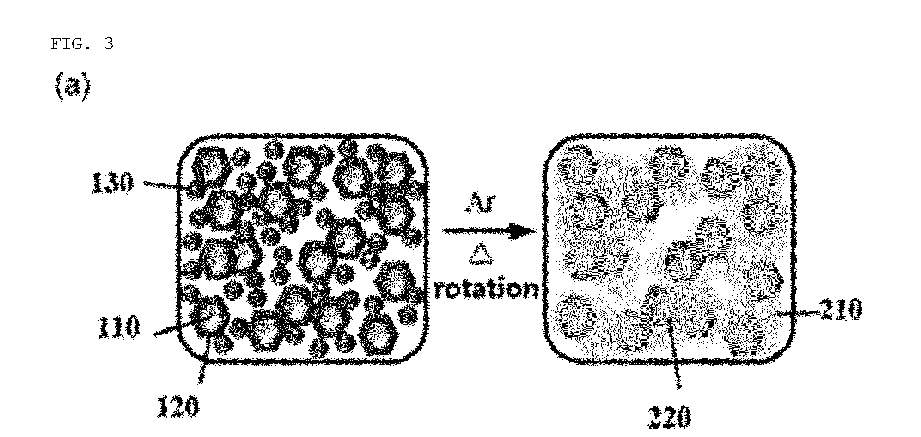
- FIG. 3 illustrates step (3) in which the second mixture is fed into a rotary reaction chamber, followed by reducing the silicon precursor through secondary heat treatment while rotating the chamber.
- the rotary reaction chamber may be a closed or open type, with a preference for a closed type in terms of the efficiency of the reducing agent.
- the chamber revolves at a speed of 1 to 1,000 revolutions per minute and more particularly at a speed of 10 to 100 revolutions per minute.
- revolution speed is less than one rpm, the mixing and reducing reaction effects attributed to the revolution are insignificant.
- Revolution at more than 1,000 rpm generates an excessive centrifugal force that acts on the mixture in the chamber, giving rise to the problems of failing to draw forth uniform mixing and reduction reactions and causing mechanical defects in the chamber.
- rotary reactors including rotary kiln reactors may be used without limitations.
- the second heat treatment may be carried out at a temperature of 300 to 1,000°C for 1 to 24 hours under a pressure of 10 -3 to 5 bar and particularly at a temperature of 650 to 800°C under a pressure of 10 -2 to 2 bar for 2 to 5 hours in a non-oxidative atmosphere.
- a temperature less than n 300°C for the secondary heat treatment does not melt the metal reducing agent and fails in uniform reduction and reaction heat control, with a resultant decrease in the reduction rate of the silicon precursor and the yield of the porous silicon.
- the secondary heat treatment is carried out at higher than 1,000°C, the particles undergo sintering to increase the diameter of the primary silicon particles and the pores are not sufficiently formed. At such a temperature, side reactions occur to decrease the purity of the porous silicon.
- the heat treatment temperature may be set forth in a suitable range depending on the metal reducing agent used and, in consideration of the melting point (Tm) of the metal reducing agent, may particularly range from T m to T m + 250°C.
- the reducing agent may participate in metallothermic reduction as a vapor or liquid phase.
- the non-oxidative atmosphere may be an oxygen-free atmosphere like inert gas, such as argon, etc., or a mixture of inert gas and hydrogen. Under this condition, the silicon precursor can be reduced by the metal reducing agent in a liquid- or gas-phase state.
- step (4) the reduction product obtained by the secondary heat treatment is washed to recover porous silicon.
- the reaction product obtained by the secondary heat treatment may include unreacted silicon precursor and metal reducing agent and by-products such as magnesium silicide (Mg 2 Si), etc. in addition to porous silicon and oxidized metal reducing agent.
- a washing process with water and an acidic solution removes the heat dispersant, by-products, and unreacted silicon precursors from the reaction product while recovering the porous silicon.
- the step of washing and etching the reaction product to recover porous silicon may include the sub-steps of: (4-1) washing the reaction product with distilled water to remove the heat dispersant; (4-2) washing the reaction product with a first acidic solution to remove by-products; and etching the reaction product with a second acid solution to remove remaining silicon precursors.
- the first and the second acidic solution may each be independently hydrochloric acid (HCl), acetic acid, hydrofluoric acid (HF), or a combination thereof.
- the water used in the washing step (4-1) is distilled water. This washing step is carried out for 1 to 10 hours and particularly for 4 to 6 hours.
- the first acidic solution used in the washing step (4-2) is limited to specific types, but may be particularly hydrochloric acid. This step may be carried out for 1 to 10 hours using the first acid solution at a concentration of 0.01 to 8 M and particularly for 4 to 6 hours using the first acid solution at a concentration of 0.05 to 5 M. when the concentration of the first acidic solution is less than 0.01 M, the by-products are insufficiently removed. At higher than 8 M, the first acidic solution vaporizes to generate harmful gas which corrodes the working environment and is hazardous to the worker.
- Preferable is hydrofluoric acid (HF).
- This step may be carried out for 1 to 10 hours using the secondary acidic solution at a concentration of 0.1 to 40 v/v% based on the total volume thereof and particularly for 4 to 6 hours using the secondary acidic solution at a concentration of 0.5 to 20 v/v% based on the total volume thereof.
- the second acidic solution has a concentration of less than 0.1 v/v%, the remaining silicon precursor is insufficiently removed.
- the second acidic solution vaporizes to form harmful gas that corrodes the working environment and is hazardous to the worker.
- the porous silicon recovered after the washing and etching processes suggested in steps (4-2) to (4-3) has a specific surface area of 20 to 200 m 2 /g and a total pore volume of 0.1 to 1.0 cm 3 /g as measured by a BET method, and the primary silicon particles as a constituent for the porous silicon may range in average diameter from 10 to 50 nm.
- the present disclosure provides a method for producing a secondary battery anode active material including a porous silicon-carbon composite in which the porous silicon manufactured by the porous silicon manufacturing method is coated with carbon.
- a method for producing a secondary battery anode active material including the porous silicon-carbon composite is illustrated according to an embodiment, the method, after sequentially conducting the steps (4-1) to (4-2) on the porous silicon manufactured through the steps (1) to (3), including the steps of (5) mixing the porous silicon with a carbon precursor to form a third mixture; and (6) subjecting the third mixture to tertiary heat treatment.
- the porous silicon recovered in step (4) is coated with a carbonaceous material through mixing and heat treatment.
- FIG. 5 is a view showing the structural stability of a porous silicon-carbon composite manufactured according to an embodiment of the present disclosure in a secondary battery including the porous silicon-carbon composite during charging (lithiation) and discharging (de-lithiation).
- volumetric expansion of the porous silicon-carbon composite is absorbed by cavity 1 inside the porous silicon and cavity 2 in the carbon while the carbon coat on the porous silicon increases electric conductivity and allows for reversible lithiation and de-lithiation, whereby the porous silicon-carbon composite exhibits excellent lifespan characteristics as an electrode material for secondary batteries.
- the primary silicon particles minimize the overall volumetric expansion of the porous silicon-carbon composite.
- the carbon precursor applied on the porous silicon may include at least one of pitch, sucrose, glucose, resorcinolformaldehyde, phenol-formaldehyde, a phenolic resin, polydopamine, graphite, carbon black, carbon nanotubes, and graphene.
- the tertiary heat treatment may be carried out at 600 to 1000°C and particularly at 700 to 900°C in an inert gas atmosphere or in a mixed atmosphere of inert gas and hydrogen.
- the carbon precursor which is a constituent of the secondary battery electrode, forms underdeveloped carbon hexahedrons and carbon layers so that the battery exhibits a poor cycle characteristic although increasing in capacity.
- the carbon precursor increases in crystallinity with the removal of hydrogen atoms therefrom, causing the battery to increase in cycle characteristic but to decrease in capacity.
- the content of the porous silicon in the porous silicon-carbon composite may be 10 to 80 wt%, based on the total weight of the porous silicon-carbon.
- FIG. 4 a method for producing a secondary battery anode active material is illustrated according to another embodiment of the present disclosure, the method, after conducting the step (4-1) on the porous silicon manufactured through the steps (1) to (3), including the steps of: (5) mixing the porous silicon with a carbon precursor to form a third mixture; (6) subjecting the third mixture to tertiary heat treatment to afford the secondary battery anode active material containing a porous silicon-carbon composite; (4-2) washing the secondary battery anode active material with a first acidic solution to remove by-products; (4-3) etching the secondary battery anode active material with a second acidic solution to remove remaining silicon precursors; and (7) subjecting the secondary battery anode active material containing the porous silicon-carbon composite to a quaternary heat treatment to additionally reduce the surface of the active material.
- the quaternary heat treatment in step (7) may be conducted at 600 to 1,000°C and particularly at 700°C to 900°C in an inert gas atmosphere or a mixed atmosphere of inert gas and hydrogen.
- the quaternary heat treatment is conducted at less than 600°C, the reduction is insufficient.
- a temperature higher than 1,000°C causes side reactions.
- the content of the porous silicon in the porous silicon-carbon composite may range from 10 to 80 wt%, based on the total weight of the porous silicon-carbon composite.
- the porous silicon-carbon composite-containing secondary battery anode active material according to the present disclosure can be used as an electrode for a secondary battery.
- the electrode can be also a constituent in power storage devices and electric devices in addition to secondary batteries.
- the use of the porous silicon-carbon composite-containing secondary battery anode active material is not limited to those described in the specification. No particular limitations are imparted into the uses of the anode active material if the secondary battery inclusive of an electrode containing the anode active material is a component in power supply systems.
- the electronic device may be a mobile device such as an electric vehicle, a smartphone, a watch, etc.
- the electronic device may include electronic parts such as microprocessors, etc., and may be designed to operate the electronic parts while receiving power from the secondary battery.
- Step (1) Mixing zeolite as silicon precursor and sodium chloride as heat dispersant, followed by heat treatment
- Steps (2) to (4-3) Recovery of porous silicon through washing and etching subsequent to rotary thermal reduction
- This mixture was loaded into a reaction chamber made of a closed Swagelok tube under an argon atmosphere in a glove box and subjected to secondary heat treatment at 750°C for 2 hours to perform magenesiothermic reduction while rotating the chamber at a speed of 3.5 rpm under 1 bar in a nitrogen atmosphere.
- the reaction product obtained as a brown powder by the heat treatment was primarily washed with distilled water to remove the heat dispersant sodium chloride and then with 1 M HCl for an additional 5 hours to remove by-products such as magnesium oxide (MgO) or magnesium silicide (Mg 2 Si).
- the silicon precursor remaining incompletely reduced was removed by etching with 5 v/v% HF for 5 hours to recover porous silicon.
- Steps (5) to (6) Production of secondary battery anode active material containing porous silicon-carbon composite obtained by coating porous silicon with carbon
- the recovered porous silicon was completely dispersed in tetrahydrofuran (THF) by ultrasonic vibration.
- Pitch carbon was completely dissolved in THF by ultrasonic vibration and stirring and then added with the dispersion of the porous silicon in THF.
- the mixture was stirred at room temperature for 3 hours and then at 70 to 80°C until the solvent completely vaporized.
- the porous silicon-carbon precursor mixture thus obtained was dried at 80°C for 12 hours in a drier, subjected to tertiary heat treatment at 800°C for 4 hours under a flow of argon gas in a tube heater, and then let to be cooled spontaneously.
- the porous silicon-carbon composite was made to have a silicon content of 41 wt%.
- a porous silicon-carbon composite was produced in the same manner as in Example 1, with the exception that the secondary heat treatment in step (3) was carried out at 750°C for 5 hours.
- a porous silicon-carbon composite was produced in the same manner as in Example 1, with the exception that the secondary heat treatment was carried out while the rotary reaction chamber in step (3) was rotated at a speed of 17 rpm.
- a porous silicon-carbon composite was produced in the same manner as in Example 1, with the exception that the secondary heat treatment was carried out at 750°C for 5 hours while the rotary reaction chamber in step (3) was rotated at 17 rpm, and the etching process with hydrochloric acid solution in step (4) was not conducted.
- a porous silicon-carbon composite was produced in the same manner as in Example 1, with the exception that the secondary heat treatment was carried out at 750°C for 5 hours while the rotary reaction chamber in step (3) was rotated at a speed of 17 rpm.
- Step (1) Mixing zeolite as silicon precursor and sodium chloride as heat dispersant, followed by heat treatment
- Steps (2) to (4-1) Recovery of porous silicon through rotary thermal reduction and washing with water
- This mixture was loaded into a reaction chamber made of a closed Swagelok tube under an argon atmosphere in a glove box and subjected to secondary heat treatment at 750°C for 2 hours to perform magenesiothermic reduction while rotating the chamber at a speed of 3.5 rpm under 1 bar in a nitrogen atmosphere.
- the reaction product obtained as a brown powder by the heat treatment was primarily washed with distilled water to remove the heat dispersant sodium chloride.
- Steps (5) to (6) Preparation of porous silicon-carbon composite by coating porous silicon with carbon
- porous silicon-containing brown mixture deprived of the heat dispersant was completely dispersed in tetrahydrofuran (THF) by ultrasonic vibration.
- Pitch carbon was completely dissolved in THF by ultrasonic vibration and stirring and then added with the dispersion of the porous silicon in THF.
- the mixture was stirred at room temperature for 3 hours and then at 70 to 80°C until the solvent completely vaporized.
- the porous silicon-carbon precursor mixture thus obtained was dried at 80°C for 12 hours in a drier.
- the dried powder was input into a jar and subjected to tertiary heat treatment at 650°C for 5 hours under a flow of argon gas in a tube heater, and then let to be cooled spontaneously.
- the porous silicon-carbon composite was made to have a silicon content of 41 wt%.
- the silicon-carbon composite obtained above was pickled with 2 M HCl to remove by-products such as magnesium oxide (MgO) or magnesium silicide (Mg 2 Si).
- the silicon precursor remaining incompletely reduced was removed by etching with 5 v/v% HF for 5 hours to recover porous silicon.
- Step (7) Surface reduction of porous silicon-carbon composite
- the washed and etched porous silicon-carbon composite was loaded into a jar and then subjected to quaternary heat treatment at 800°C for 4 hours under a flow of argon gas in a tube heater, followed by spontaneously cooling.
- the surface-reduced porous silicon-carbon composite obtained in Example 6 and graphite were mixed at a weight ratio of 50 : 50 wt% to prepare a secondary battery anode active material containing the porous silicon-carbon composite.
- porous silicon-carbon composite of Example 4 As an anode active material for a secondary battery, carbon black as a conductive material, and a 5 wt% polyvinyl acetate (PVA) solution in dimethyl sulfoxide (DMSO) as a polymer binder.
- the porous silicon-carbon composite, the conductive material, and the polymer binder were mixed at a weight ratio of 70:20:10 to give a mixture in a slurry state.
- the mixture in a slurry state was applied at a thickness of 30 ⁇ m to a 10 ⁇ m-thick copper plate as a copper current collector, dried at 80°C for 2 hours, and compressed into a thickness of 10 ⁇ m.
- the compressed current collector was dried at 80°C for 2 hours in a vacuum to afford an anode active material-containing secondary battery anode with an area of 1.54 cm 2 .
- the secondary battery anode and the lithium metal reference electrode were deposited on a 2032 coin cell, with a 2.54cm 2 polypropylene (PP) separator inserted therebetween.
- PP polypropylene
- a lithium secondary battery was fabricated using as an electrolyte a 10 vol% fluoroethylene carbonate-added solution in which ethylene carbonate, ethylmethyl carbonate, and diethyl carbonate were mixed at a volume ratio of 30:40:30 in an organic solvent containing 1.2M LiPF 6 salt.
- a lithium secondary battery was fabricated in the same manner as in Example 8, with the exception that the porous silicon-carbon composite of Example 6 was used, instead of that of Example 4, as an anode active material for a secondary battery.
- a lithium secondary battery was fabricated in the same manner as in Example 8, with the exception that the porous silicon-carbon composite of Example 7 was used, instead of that of Example 4, as an anode active material for a secondary battery.
- a porous silicon-carbon composite-containing secondary battery anode active material was produced in the same manner as in Example 2, with the exception that the magnesiothermic reduction was carried out by the secondary heat treatment while the rotary reaction chamber was not rotated, but in a stagnant state.
- the porous silicon-carbon composite was made to have a silicon content of 60 wt%.
- a porous silicon-carbon composite-containing secondary battery anode active material was produced in the same manner as in Example 2, with the exception that the magnesiothermic reduction was carried out in a vacuum by the secondary heat treatment while the rotary reaction chamber was not rotated, but in a stagnant state.
- a porous silicon-carbon composite-containing secondary battery anode active material was produced in the same manner as in Example 3, with the exception that the magnesiothermic reduction was carried out by physically mixing sodium chloride and magnesium powder after the primary heat treatment on zeolite Y alone at 700°C for 5 hours.
- a commercially available porous silicon-carbon composite-containing secondary battery anode active material was produced in the same manner as in Example 1, with the exception that commercially available silicon nanoparticles with a particle size of 70 to 100 nm were used instead of the porous silicon.
- the porous silicon-carbon composite was made to have a silicon content of 56 wt%.
- a lithium secondary battery was fabricated in the same manner as in Example 8, with the exception that the commercially available silicon-carbon composite of Comparative Example 4 was used, instead of the porous silicon-carbon composite of Example 4, as an anode active material for a secondary battery.
- FE-SEM field emission scanning electron microscope
- TEM transmission electron microscope
- HP-XPS high-performance X-ray photoelectron spectrophotometer
- XRD X-ray diffraction
- FIG. 6 shows an SEM image of the silicon precursor zeolite Y (a) and a TEM image of the porous silicon particles of Example 4 (b).
- zeolite Y used as a raw material had a particle diameter of 500 nm to 1 ⁇ m and exhibited a smooth surface and the porous silicon manufactured in Example 4 retained well-developed porous structures with the primary silicon particles thereof being small in size.
- magnesiothermic reduction products obtained in Examples 2 to 4 and Comparative Example 1 were washed with distilled water to remove the heat dispersant and then subjected to XPS Mg 2p spectrometry. Along with the analysis results, conversion rates are depicted in FIG. 7 . In addition, conversion rates into individual components in the magnesiothermic reduction products were calculated according Equations 9 to 11 and are shown, together with the experimental yields and the sizes of primary silicon particles, in Table 3 and FIG. 8 . Reaction conversion rates were calculated using the Mg 2p analysis results highly sensitive for the mixtures obtained in Examples 2 to 4 and Comparative Example 1 and the Mg 1s analysis results highly sensitive for Mg 2 SiO 4 for Comparative Example 3.
- Mg 1s analysis results of Example 4 and Comparative Example 1 are depicted in FIG. 7 .
- Conversion rate into Mg 2 p reference magnesium oxide MgO unit : % Mg f ⁇ Mg p / Mg f ⁇ MgO p / MgO p + Mg 2 Si p ⁇ 100 %
- the conversion rate of Comparative Example 1 in which zeolite Y, the heat dispersant (sodium chloride), and the metal reducing agent (magnesium powder) were mixed together and subjected to the reduction was 64.9%, as measured by the Mg 1s analysis method, which was lower by more than 30% than the conversion rate 97.2% of Example 4 in which a mixture of zeolite Y and the heat dispersant was thermally treated and then mixed with the metal reducing agent before the reduction. This is considered to be attributed to the fact that the mixing order of the silicon precursor, the heat dispersant, and the metal reducing agent affected by-product formation during the reduction process.
- the experimental yield for porous silicon in Comparative Example 3 was 70.6%, which was higher than the conversion rate into magnesium oxide (MgO) due to the fact that stable MgF 2 was incorporated into the calculation for the yield of the final product after being formed from Mg 2 SiO 4 by etching treatment with hydrofluoric acid (HF), as shown in Equation 8.
- MgF 2 remained as an impurity in the final porous silicon obtained by pickling, thereby decreasing the purity of the final porous silicon product.
- X-ray diffraction (XRD) profiles obtained according to washing step in Examples 2 and 4 and Comparative Examples 1 and 2 are depicted in FIG. 9 .
- HF hydrochloric acid
- the XRD analysis data indicate that the reduction product washed with distilled water in Comparative Example 1 where the reaction chamber was not rotated contained a larger amount of Mg 2 Si, compared to the Examples where the reaction chamber was rotated.
- MgO and Mg 2 Si were more abundant in Example 2 where the rotation speed was 3.5 rpm, compared to Examples 4 and 5 where the rotation speed was 17 rpm.
- Example 3 In contrast to Example 3 in which the silicon precursor (zeolite Y) and the heat dispersant (sodium chloride) were mixed with other and then with magnesium powder, which the silicon precursor, sodium chloride, and magnesium powder were mixed simultaneously in Comparative Example 3.
- the mixing order of the silicon precursor, the heat dispersant, and the metal reducing agent or whether the heat dispersant is pretreated or not is considered to affect the formation of by-products in the reduction process.
- FIG. 10 TEM images of focused ion beam (FIB)-cut cross sections of the porous silicon particles obtained in Example 4 and Si element mapping images are shown in FIG. 10 .
- FIGS. 10(a) and 10(b) porous silicon particles were observed to have pores formed therein.
- FIG. 10(c) showing a TEM image of high magnification, the primary silicon particles were observed to have a diameter of 30 to 40 nm.
- FIG. 10(d) showing a Si element mapping image for FIG. 10(c)
- small primary silicon particles aggregated and were connected to each other to form large particles which had pores developed therein.
- zeolite Y which was used as a silicon precursor, is a micropore material with a large BET surface area and pore volume.
- the porous silicon-carbon composite prepared in Example 6 had a BET surface area of 113.9 m 2 /g and a pore volume of 0.43 cm 3 /g, which were larger than the surface areas and pore volumes of the porous silicon of Examples 3 and 5.
- the enlargement in surface area and pore volume is construed to result from the formation of pores in the carbon layer as well as the porous silicon in the washing and etching processes after carbon coating.
- the average pore size of the porous silicon-carbon composite was decreased to 18.2 nm due to the carbon coating.
- the porous silicon-carbon composites in Examples 2, 4, and 6 were analyzed by TGA in an air atmosphere and the results are depicted in FIG. 11 .
- the composites in Examples 2 and 4 both had a silicon content of 41.0% while the composite prepared in Example 6 includes silicon at a content of 39.1%.
- the porous silicon-carbon composite obtained in Example 4 was examined for the distribution of silicon and carbon over the inside and outside thereof.
- the composite was cut with FIB and the cross sections thus exposed were analyzed by TEM and subjected to element mapping. The results are depicted.
- FIG. 12(d) there is an image obtained after carbon (C) and silicon (Si) were simultaneously mapped. As shown, the porous silicon-carbon composite is uniformly coated with carbon across the inside and outside thereof.
- Example 6 The cross sections of the composite obtained in Example 6 were analyzed using TEM in the same manner as for Example 4. The results are depicted in FIG. 13 .
- Example 6 unlike Example 4, the reduction product was washed with distilled water to remove only the heat dispersant, followed by carbon coating. That is, the porous silicon and the reduction product MgO were present in the mixture and after carbon coating, pickling with HCl removed MgO.
- FIGS. 13(a) to 13(c) which are images of the porous silicon-carbon composite after carbon coating, the carbon coat layer was distributed mainly over the outer surface of the composite while MgO, a constituent of the oxidized metal reducing agent, was uniformly distributed in the inside. As shown in FIGS.
- the porous silicon-carbon composite pickled with hydrochloric acid solution after carbon coating retained the carbon coat layer and the porous silicon while MgO distributed inside the particles was removed. Accordingly, the carbon coat layer was distributed mainly on the outside of the particles while the porous silicon was found predominantly inside the particles. In other words, the porous silicon-carbon composite prepared in Example 6 had more pores distributed therein, compared to that prepared in Example 4 where carbon coating was performed after preparation of the porous silicon.
- charge/discharge cycles were measured in the voltage range of 0.01 to 1.5 V by a constant current method.
- FIG. 14 shows a comparison of charge/discharge cycle characteristics between lithium secondary batteries of Example 8 and Comparative Examples 5.
- Charge/discharge cycle tests started with one cycle at a current density of 50 mA/g and proceeded with five cycles at a current density of 100 mA/g, and subsequent cycles were performed at a current density of 500 - 1,000 mA/g.
- the capacity of the lithium secondary battery of Comparative Example 5 that included commercially available silicon nanoparticles declined drastically during the first 6 cycles at a current density of 100 mA/g or less, then rapidly during about 20 cycles at a current density of 500 mA/g, gradually during 300 cycles, and finally to 182 mAh/g in the next 300 cycles.
- the porous silicon-carbon composite of Example 8 retained a capacity of 1,290 mAh/g at a current density of 100 mA/g or less.
- the capacity in the composite decreased to 985 mAh/g at a current density of 500 mA/g and then was maintained at 800 mAh/g or more until 100 cycles.
- the capacity decreased to 600 mAh/g at a current density of 1,000 mA/g and was then stably maintained until 300 cycles.
- the final capacity after 300 cycles was 300% higher than that of Comparative Example 5, with the charge/discharge efficiency recorded at 99.9% or higher. Therefore, the secondary battery of Example 8 according to the present disclosure exhibited remarkably high capacity and long lifespan characteristics, compared to the secondary battery containing the commercially available silicon nanoparticle-carbon composite of Comparative Example 5.
- FIG. 15 shows the charge/discharge cycle performance of the lithium secondary batteries (half-cell fabricated with lithium metal serving as a reference electrode) including electrodes made of the anode active materials containing the porous silicon-carbon composites prepared in Examples 9 and 10.
- the lithium secondary battery which employed the anode active material containing the porous silicon-carbon composite in Example 9 was measured to have a capacity of 1,170 to 1,240 mAh/g at a current density of 100 mA/g.
- the capacity drastically decreased to 690 mAh/g at a current density of 500 mAh/g in the initial phase and then was stably maintained at a level of 570 mAh/g until 250 cycles, with the charge/discharge efficiency recorded at 99.5%.
- the secondary battery of Example 9 was superior to that of Comparative Example 5 in terms of capacity and cycle lifespan, but inferior to that of Example 8 where magnesiothermic reduction was conducted while the chamber was rotated at a speed of 17 rpm. This is construed to result from the fact that the porous silicon-carbon composite of Example 6 contained in the secondary battery of Example 9 had many pores distributed therein (see FIG. 13d ), which is advantageous for absorbing volumetric expansion, but decreases conductivity and charge mobility within the inside of the electrode.
- the secondary battery of Example 10 was fabricated with the porous silicon-carbon composite of Example 7 in which the porous silicon-carbon composite of Example 6 was mixed with graphite at a weight ratio of 50:50 and analyzed for electrochemical characteristics. The results are depicted in FIG. 15(b) .
- the capacity of the secondary battery decreased to 900 to 910 mAh/g at a current density of 100 mA/g and drastically to 540 mAh/g at a current density of 500 mA/g until 11 cycles.
- the secondary battery stably retained a capacity of about 607 mAh/g until 450 cycles, with an excellent charge/discharge efficiency recorded at 99.9% or higher.
- the secondary batteries of Examples 8 to 10 were at least 10% higher in discharge capacity and capacity retention at the same density current, which are both indices for rate capability. Therefore, the application of an anode active material containing the porous silicon according to the Examples of the present disclosure to a secondary battery guarantees the secondary battery highcapacity and long lifespan characteristics.
- the secondary batteries of Examples 8 to 10 and Comparative Example 5 were measured for cross-sectional thickness changes in the electrodes used therein after the charge/discharge cycle tests of Experimental Example 9 by SEM analysis. The results are depicted in FIG. 16 .
- the secondary battery of Comparative Example 5 which employed a commercially silicon nanoparticle-carbon composite underwent volumetric expansion leading to cracking the cross section of the electrode.
- the electrode thickened to 161 ⁇ m which increased by 494% compared to 32.6 ⁇ m, which was the thickness before the cycle test ( FIG. 16 (a) ).
- the accumulation of charge/discharge cycles caused electrode destruction and lost the conductive network.
- the capacity drastically decreased as the cycle proceeded, as shown in FIG. 14 .
- the secondary battery of Example 8 which employed the porous silicon nanoparticle-carbon composite of the present disclosure, was measured to have an electrode thickness of 15.63 ⁇ m after 200 cycles, which increased by only 7.6 %, compared to 14.53 ⁇ m, the thickness before the cycle test ( FIG. 16(b) ).
- the secondary battery of Example 10 which employed the porous silicon nanoparticle-carbon composite of the present disclosure was measured to have an electrode thickness of 20.82 ⁇ m after 250 cycles, which increased by 55 %, compared to 13.51 ⁇ m, the thickness before the cycle test ( FIG. 16(c) ). Therefore, the structure of the porous silicon effectively absorbs the volumetric expansion of silicon caused by charge/discharge. When an anode active material containing the porous silicon is applied thereto, the secondary battery can exhibit high capacity and long lifespan characteristics.
Landscapes
- Chemical & Material Sciences (AREA)
- Chemical Kinetics & Catalysis (AREA)
- Electrochemistry (AREA)
- General Chemical & Material Sciences (AREA)
- Organic Chemistry (AREA)
- Inorganic Chemistry (AREA)
- Engineering & Computer Science (AREA)
- Composite Materials (AREA)
- Manufacturing & Machinery (AREA)
- Materials Engineering (AREA)
- Battery Electrode And Active Subsutance (AREA)
- Silicon Compounds (AREA)
Abstract
Description
- The present disclosure relates to porous silicon, a secondary battery anode active material containing same, a manufacturing method therefor, and an electrode and a secondary battery, each containing the secondary battery anode active material for a secondary battery.
- To improve the efficiency of electric vehicles and largecapacity energy storage systems, extensive research is being actively conducted on lithium secondary batteries. With the increase in the need for secondary batteries as storage devices with high energy density (Wh/kg or Wh/l), high power density (W/kg or W/l), and high stability, research and development have been focused on cathode and anode materials, separators, and electrolytes, which are all key elements of secondary batteries.
- Since the commercialization of lithium secondary batteries, graphite has been used as an anode material. This material enjoys the advantages of low price, low driving voltage, and excellent lifetime stability. However, graphite has a low theoretical capacity of about 372 mAh/g and suffers from the disadvantage of being poor in rate capability due to its low storage (charging) rate of lithium ions, thereby being limited in application as an anode material for high-performance secondary batteries. With the development of high-capacity cathode materials, the graphite anode material needs to be coated more thickly, but when a high current density is applied to the graphite anode material, lithium metal is precipitated due to a slow storage rate of lithium ions to form dendrites, thereby increasing the risk of explosion.
- As the need for developing a high-capacity anode material capable of replacing low-capacity and low-power graphite is emerging, metals in IV and V groups, such as Si, Sn, Ge, Pb, As, Bi, etc., which serve as an alternative anode material to form an electrochemical alloy with lithium, are extensively being studied.
- Among them, silicon, which is a highly abundant resource on earth, is one of the most promising anode materials due to its relatively low driving voltage (~0.4 V) and high theoretical capacity (~3,579 mAh/g). However, silicon is low in electric conductivity. Moreover, as silicon reacts with up to about four lithium ions per silicon atom during repeated charge/discharge cycles, it expands in volume by about 280 %, causing electrode fracture. In addition, the reaction between the newly created silicon surface and the electrolyte in this process continuously creates a solid electrolyte interface (SEI) and provokes high initial irreversible capacity, high resistance formation, and drastic capacity reduction, giving rise to a decrease in the lifespan of the secondary batteries.
- To solve the problems caused by the volume expansion of silicon, many attempts have been made to form porous silicon particles so that the volume expansion is absorbed inside the silicon particles. Various porous silicon manufacturing methods, such as chemical or electrochemical etching methods for silicon wafers, etching methods induced by metals doped to commercially available silicon particles, etc. have been reported, but they have limitations in their use as economical mass production methods due to the use of expensive raw materials, low silicon yield, high-cost process, and excessive use of harmful chemicals such as hydrofluoric acid.
- Non-patent
literature 1 discloses a method for manufacturing porous silicon through magnesiothermic reduction of various forms of silica (Z. Bao et al., Nature, 2007, 446, 172). The reduction of silica using magnesium as a reductant can be expressed asEquation 1, below. This reaction is conducted at as low as 650°C with the concomitant generation of very great heat. The high heat generated induces intra- and interparticle sintering, which increases the size of primary silicon particles and causes a problem in maintaining the porous structure. As an alternative,non-patent literature 2 discloses a method in which inorganic mineral additives with large heat capacity, such as sodium chloride (NaCl, △Hfus=28.8 kJ/mol), etc., are used as a heat dispersant (W. Luo, et al., Sci. Rep., 2013, 3, 2222). If the reduction temperature remains high or the high heat generation is not controlled despite the addition of a heat dispersant, Mg2SiO4 with a very stable structure is generated according toEquation 2. Under the condition that the molar ratio of Mg to SiO2 deviates from the stoichiometric ratio of 2:1, Mg2Si is by-produced according toEquations 


- As illustrated in
Equation 5, magnesium oxide (MgO) produced according toEquation 1 can be removed by pickling with a hydrochloric acid (HCl) solution. In addition, as described inEquation 6, the by-product Mg2Si inEquations - High purity and high yield of porous silicon are achieved by removing SiO2 through etching with an aqueous hydrofluoric acid (HF) solution as shown in
Equation 7. To avoid the poisonous hydrofluoric acid etching process or to minimize the amount of hydrofluoric acid used, it is preferable to increase the conversion rate of the silicon precursor in the magnesium reduction reaction ofEquation 1 and suppress the Mg2Si side reaction ofEquations - In addition, since Mg2SiO4 generated in
Equation 2 is stable, even when hydrofluoric acid etching is performed, stable MgF2 is formed according toEquation 8 below to lower the purity of the finally obtained silicon. Thus, it is preferable to also suppress the production of Mg2SiO4.


- However, in the conventional magnesium thermal reduction method shown in
FIG. 1 , an open reaction system under an inert gas flow (FIG. 1(a) ) or a closed reaction system under an inert gas atmosphere (FIG. 1(b) ) is applied, and the reaction proceeds while the reaction chamber is kept in a fixed state. - With reference to
FIGS. 1(a) and 1(b) , in the case of an open reaction system under an inert gas flow, magnesium which is used as a metal reducing agent undergoes evaporative loss or it is difficult to uniformly mix magnesium and silicon precursors. In addition, since the molar ratio of Mg and SiO2 cannot form a stoichiometric ratio of 2:1 at all points inside the reaction chamber, side reactions ofEquations 2 to 4 are unavoidable so that the yield of porous silicon is mostly lowered to 50% or less. Furthermore, the system requires a complex purification process such as etching with harmful hydrofluoric acid (HF) for attaining highly pure silicon. - If not controlled, the high reaction heat generated in the magnesiothermic reduction provokes the side reactions of
Equations 2 to 4 and sinters silicon particles, increasing the size of the silicon primary particles for porous silicon and limiting the development of pores. - Related
art patent literatures FIG. 1(b) , and thus suffers from the problem of side reactions and sintering phenomena between silicon particles. - To solve the problems raised upon the production of porous silicon particles through magnesiothermic reaction, a rotatable reaction chamber, and an optimal mixing order of ingredients fed thereto are applied to the magnesiothermic reaction, leading to the development of a method for manufacturing porous silicon, which can suppress the side reactions of
Equations 2 to 4, achieve a high conversion rate of silicon precursors, and remarkably increase the yield of porous silicon through a simple purification process. -
- (Patent literature 1)
Korean Patent Number 10-0493960 (issued June 10, 2005 - (Patent literature 2)
Korean Patent Number 10-1573423 (issued December 02, 2015 -
- (Non-Patent literature 1) Z. Bao et al., Nature, 2007, 446, 172-175
- (Non-Patent literature 2) W. Luo et al., Sci. Rep., 2013, 3, 2222
- An aspect of the present disclosure is to provide a method for manufacturing porous silicon with high purity and high yield and a method for producing a secondary battery anode active material containing the porous silicon, whereby the problems with silicon as a secondary battery anode material, including volume expansion and resultant short lifespan characteristics, can be solved.
- Another aspect of the present disclosure is to provide a secondary battery anode active material with high capacity and long lifespan characteristics, produced by the production method, which exhibits excellent charge/discharge cycle efficiency and effectively absorbs volumetric changes with charging and discharging.
- A further aspect of the present disclosure is to provide a secondary battery anode containing the secondary battery anode active material and an electrode, a secondary battery, a power storage device, and an electronic device, each including the anode.
- In accordance with an aspect thereof, the present disclosure provides a method for manufacturing porous silicon, the method including the steps of: (1) conducting primary heat treatment on a first mixture containing a silicon precursor and a heat dispersant; (2) feeding a metal reducing agent to the first mixture and stirring same to form a second mixture; (3) subjecting the second mixture to a secondary heat treatment in a rotary reaction chamber; and (4) washing the secondarily heat-treated second mixture with a solvent to recover porous silicon particles.
- In an embodiment of the present disclosure, the silicon precursor may be in various forms with various particle sizes and may be any one of silicon dioxide (SiO2), silicon oxide (SiOx, 0<x<2), silica gel, sand, glass, quartz, zeolite, and fumed silica.
- In another embodiment of the present disclosure, the heat dispersant may be any one of sodium chloride (NaCl), potassium chloride (KCl), calcium chloride (CaCl2), and magnesium chloride (MgCl2).
- The heat dispersant may be contained at an amount of 100 to 1,200 parts by weight, based on 100 parts by weight of the silicon precursor.
- The primary heat treatment is conducted at a temperature of 550 to 800°C for 1 to 5 hours.
- In an embodiment of the present disclosure, the metal dispersant may be selected from sodium (Na), magnesium (Mg), aluminum (Al), and a combination thereof.
- The metal reducing agent may be used at an amount of 50 to 200 parts by weight, based on 100 parts by weight of the silicon precursor.
- The secondary heat treatment is carried out at a temperature of 300 to 1,000°C for 1 to 24 hours under a pressure of 10-3 to 5 bar in a non-oxidative atmosphere.
- The secondary heat treatment is carried out while the rotary reaction chamber revolves 1 to 1,000 times per minute.
- Step (4) is carried out by the sub-steps of: (4-1) washing the secondarily heat-treated reaction product with distilled water to remove the heat dispersant; (4-2) washing the heat dispersant-removed reaction product with a first acid solution to remove the oxidized metal reducing agent and recover the porous silicon; and (4-3) etching the recovered porous silicon with a second acid solution to remove impurities therefrom.
- In an embodiment of the present disclosure, the porous silicon particles recovered in step (4) have a specific surface area of 20 to 200 m2/g and a total pore volume of 0.1 cm3/g to 1.0 cm3/g as measured by a BET method; and individual primary silicon particles as constituents in the porous silicon particles have an average size of 10 to 50 nm.
- A method for producing a secondary battery anode active material according to the present disclosure may employ the porous silicon manufactured using the method for manufacturing porous silicon.
- The method for producing a secondary battery anode active material further includes a carbon coating step (5).
- In an embodiment of the present disclosure, the carbon coating step (5) may be carried out just after step (4-1) or (4-3) wherein when the carbon coating step (5) is carried out just after step (4-1), a tertiary heat treatment is conducted before steps (4-2) to (4-3).
- The carbon coating step (5) includes conducting a tertiary heat treatment on a third mixture of the recovery reaction product and a carbon precursor.
- The secondary battery anode active material containing the porous silicon according to the present disclosure may be produced by the method for producing a secondary battery anode active material.
- In addition, the electrode for a secondary battery according to the present disclosure may include the secondary battery anode active material.
- Furthermore, the secondary battery of the present disclosure may include the electrode for a secondary battery.
- Moreover, the power supply system may employ the secondary battery.
- In the method for manufacturing porous silicon according to the present disclosure, a mixture of the silicon precursor coated uniformly with a heat dispersant and the metal reducing agent is thermally treated in a rotation state to decrease the reaction heat accumulated in the porous silicon, whereby the silicon particles can be restrained from being sintered and the melted metal reducing agent can diffuse over the silicon precursor at an increased rate while a uniform admixture therebetween is allowed.
- Also, approximation of the reaction molar ratio of Mg and SiO2 in
Equation 1 to the stoichiometric ratio of Mg: SiO2 = 2: 1 increases the conversion rate of the silicon precursor, decreases the size of the primary silicon particles, and represses the production of by-products such as Mg2Si and Mg2SiO4, thereby allowing for mass production of porous silicon particles with high yield and high purity. - As a porous silicon-carbon composite, the secondary battery anode active material provided by the present disclosure has a cavity inside the silicon particles and/or the carbon layer and thus can buffer the volumetric change generated during charging/discharging when used as an anode material, exhibiting high capacity and long lifespan characteristics.
- In addition, the use of the secondary battery anode active material provided by the present disclosure can guarantee high capacity and long lifespan characteristics for an electrode for a secondary battery, a secondary battery, a power storage device, and an electronic device.
-
-
FIG. 1 shows conventional magensiothermic reduction methods in an open reaction system under a flow of inert gas (a) and in a closed reaction system under an inert gas atmosphere (b). -
FIG. 2 is a block diagram illustrating a method for manufacturing porous silicon according to the present disclosure. -
FIG. 3 schematically shows compositions of reactants used in a method for manufacturing porous silicon according to the present disclosure and distribution of the reactants in a rotary reaction chamber (a) and a rotary reaction chamber used in magnesiothermic reduction (b). -
FIG. 4 illustrates a method for producing anode active materials including porous silicon-carbon composites according to Examples 1 to 7 and Comparative Examples 1 to 3. -
FIG. 5 is a schematic view illustrating the structural stability of the porous silicon-carbon composite used as a lithium secondary battery anode active material wherein pores (pore 1) in the porous silicon particles and pores (pore 2) in the carbon layer effectively absorb volumetric expansion during repeated cycles of charging (lithiation) and discharging (de-lithiation). -
FIG. 6 shows an SEM image of the silicon precursor zeolite Y used as a silicon precursor in Examples 1 to 7 and Comparative Examples 1 to 3 (a) and a TEM image of theporous silicon particles 4 in Example 4 (b). -
FIG. 7 shows profiles of mixtures of silicon precursors and metal reducing agents after removal of heat dispersants by heat treatment and washing with distilled water, as analyzed by high-performance X-ray photoelectron spectroscopy for dissolving Mg 2p spectra and peaks into MgO, Mg, and Mg2Si peaks for (a) Example 2, (b) Example 3, (c) Example 4, and (d) Comparative Example 1 and for dissolving Mg 1s peaks into MgO, Mg, and Mg2SiO4 peaks for (e) Example 4, (f) Comparative Example 1, and (g) Comparative Example 3. -
FIG. 8 shows yields of porous silicon as measured by XPS Mg 2P analysis, yields recovered in the experiments, and sizes of primary silicon particles as measured by XRD analysis in Examples 1 to 5 and Comparative Examples 1 to 3. -
FIG. 9 shows X-ray diffraction (XRD) profiles of porous silicon samples according to manufacturing steps in the Examples and the Comparative Examples [(a) Example 2, (b) Example 3, (c) Example 4, (d) Comparative Example 1, (e) Comparative Example 2, and (f) Comparative Example 3].FIG. 9(g) is an enlarged view of the section 2θ = 15~30° in the XRD profiles for Example 2 and Comparative Example 1. -
FIG. 10 shows TEM images of focused ion beam (FIB)-cut cross sections of the porous silicon particles obtained in Example 4 (a-c) and a Si element mapping image for the TEM image (d). -
FIG. 11 shows thermogravimetric analysis (TGA) profiles of porous silicon-carbon composites in Examples 2, 4, and 6. -
FIG. 12 shows focused ion beam (FIB)-cut cross sections of the porous silicon-carbon composite particles of Example 4 in terms of a TEM image (a), mapping images of carbon (C) (b) and silicon (Si) (c) for the TEM image, and a mapping image of both C and Si elements (d). -
FIG. 13 shows focused ion beam (FIB)-cut cross sections of the porous silicon-carbon composite particles after removal of the heat dispersant by washing the reduction product with distilled water and coating same with carbon in Example 6, in terms of a TEM image (a), a mapping image of all of carbon (C), magnesium (Mg), and silicon (Si) elements (b), a mapping image of both magnesium (Mg) and oxygen (O) elements (c), and a mapping image of both carbon (C) and silicon (Si) elements (d) for the TEM image, and a TEM image (e) and a mapping image of both carbon (C) and silicon (Si) (f) after removal of MgO with hydrochloric acid solution. -
FIG. 14 is a graph showing charge/discharge cycle performance of the lithium secondary batteries of Example 8 and Comparative Examples 5. -
FIG. 15 is a graph showing charge/discharge cycle performance of the lithium secondary batteries of Examples 9 and 10. -
FIG. 16 shows SEM images of cross sections of the electrodes in the secondary batteries of Examples 8 and 10 and Comparative Example 5 before and after charge/discharge cycles. - Below, a detailed description will be given of the present disclosure. In each drawing of the present disclosure, sizes or scales of components may be enlarged or reduced from their actual sizes or scales for better illustration, and known components may not be depicted therein to clearly show features of the present disclosure. Therefore, the present disclosure is not limited to the drawings. When describing the principle of the embodiments of the present disclosure in detail, details of well-known functions and features may be omitted to avoid unnecessarily obscuring the presented embodiments.
- Unless otherwise defined, all technical and scientific terms used herein have the same meanings as those typically understood by those skilled in the art to which the present disclosure belongs. In general, the nomenclature used herein is well known in the art and is typical.
- Throughout the specification, when a portion may "include" a certain constituent element, unless explicitly described to the contrary, it may not be construed to exclude another constituent element but may be construed to further include other constituent elements.
- In addition, throughout this specification, the expression of performing a step "after" or "subsequent to" a specific step means that it is performed with any subordinate order in time series, which should not be construed to be conducted successively or just after the step unless otherwise specified, such as "immediately after", etc. For instance, performing step (b) "after" or "subsequent to" step (a) means that step (b) is performed immediately following performing step (a), or step (b) may be performed after any step (c) is performed subsequent to step (a).
- Below, a detailed description will be given of a method for manufacturing porous silicon according to the present disclosure with reference to the drawings.
-
FIG. 2 is a block diagram explaining a method for manufacturing porous silicon according to Examples 1 to 5 and Comparative Example 3. Referring toFIG. 2 , the method for manufacturing porous silicon of the present disclosure includes the steps of: (1) conducting primary heat treatment on a first mixture containing a silicon precursor and a heat dispersant; (2) feeding a metal reducing agent to the first mixture and stirring same to form a second mixture; (3) subjecting the second mixture to a secondary heat treatment in a rotary reaction chamber; and (4) washing the secondarily heat-treated second mixture with a solvent to recover porous silicon particles. - Step (1) is set forth to primarily treat a first mixture containing a silicon precursor and a heat dispersant with heat to remove moisture and hydroxyl groups inside the pores of the silicon precursor and coat the silicon precursor with the heat dispersant.
- In step (1), the silicon precursor, which is a raw material used in the method for manufacturing porous silicon of the present disclosure, may be in various forms with various particle sizes and may be at least one of the well-known materials containing Si, such as silicon dioxide (SiO2), silicon oxide (SiOx, 0<x<2), silica gel, sand, glass, quartz, zeolite, fumed silica, and so on.
- Being applied to the silicon precursor, the heat dispersant functions to restrain the aggregation and sintering of the primary silicon particles from the high reaction heat generated during the heat treatment of the silicon precursor and the metal reducing agent and suppress side reactions caused by the high heat.
- The heat dispersant may be at least one of sodium chloride (NaCl), potassium chloride (KCl), calcium chloride (CaCl2), and magnesium chloride (MgCl2) and may be contained at an amount of 100 to 1,200 parts by weight and preferably at an amount of 300 to 1,000 parts by weight, based on 100 parts by weight of the silicon precursor. Less than 100 parts by weight of the heat dispersant result in a non-uniform coating over the entire silicon precursor particles whereas more than 1,200 parts by weight do not bring about an increase in the coating effect.
- The mixing of the silicon precursor and heat dispersant contained in the first mixture may be carried out in a dry or wet mixing manner, but is not limited thereto. Any well-known mixing method may be taken.
- The primary heat treatment step is performed to remove moisture and hydroxyl groups (-OH) inside the pores of the silicon precursor as well as coating the silicon precursor with the heat dispersant. Specifically, the step may be carried out in a moisture-free gas atmosphere at a temperature of 550°C to 800°C for 3 to 7 hours and particularly at a temperature of 650 to 750°C for 4 to 6 hours. When the temperature of the primary heat treatment is less than 550°C, the removal of moisture and hydroxyl group (-OH) inside the pores is insignificant. A temperature exceeding 800°C does not further increase the effect of removing moisture and hydroxyl group (-OH) inside the pores.
- In step (2), a metal reducing agent is added to and mixed with the heat dispersant-coated silicon precursor to form a second mixture.
- The metal reducing agent may be one or a mixture of metal elements in groups 1A, 2A, and 3A of the periodic table. In a particular embodiment, the metal reducing agent may be selected from sodium (Na), magnesium (Mg), calcium (Ca), aluminum (Al), and a combination thereof.
- When the metal reducing agent is a mixture of the metal elements, the mixing ratio is determined depending on the types of the metal reducing agent and the silicon precursor in consideration of the reaction molar ratios of
Equations 1 to 4. As an example of determining the mixing ratio, when the metal reducing agent and the silicon precursor are magnesium and silicon dioxide, respectively, magnesium may be mixed at an amount of 50 to 200 parts by weight and particularly at an amount of 70 to 90 parts by weight per 100 parts by weight of silicon dioxide in consideration withEquation 1. When the content of the metal reducing agent is less than 50 parts by weight or more than 200 parts by weight, the reaction molar ratio does not meet the stoichiometric ratio Mg: SiO2 = 2: 1 so that reactions of producing by-products proceed, thus decreasing the conversion rate of the silicon precursor and the yield of the porous silicon. - Prior to step (3) of subjecting the second mixture to a secondary heat treatment for reducing the silicon precursor into a reaction product, the method may further include a step of drying the second mixture of the first mixture and the metal reducing agent in a vacuum. This vacuum drying step is to remove moisture contained in the second mixture and may be carried out at a temperature of 80 to 300°C for 2 to 20 hours and particularly at a temperature of 200 to 300°C for 3 to 7 hours.
- In step (3), the silicon precursor is reduced into porous silicon through the secondary heat treatment with the concomitant oxidation of the metal reducing agent into a metal oxide.
-
FIG. 3 illustrates step (3) in which the second mixture is fed into a rotary reaction chamber, followed by reducing the silicon precursor through secondary heat treatment while rotating the chamber. Referring toFIG. 3 , the chamber is rotated to allow the silicon precursor, the heat dispersant, and the metal reducing agent to be mixed uniformly with each other, whereby the reaction molar ratio of the metal reducing agent and the silicon precursor approximates the stoichiometric ratio of Mg: SiO2 = 2: 1 throughout the reaction chamber and the side reactions are restraint, and an improvement in the conversion rate of the silicon precursor and the yield of the porous silicon is made, compared to the reaction in a stagnant state. In this regard, the rotary reaction chamber may be a closed or open type, with a preference for a closed type in terms of the efficiency of the reducing agent. - The chamber revolves at a speed of 1 to 1,000 revolutions per minute and more particularly at a speed of 10 to 100 revolutions per minute. When the revolution speed is less than one rpm, the mixing and reducing reaction effects attributed to the revolution are insignificant. Revolution at more than 1,000 rpm generates an excessive centrifugal force that acts on the mixture in the chamber, giving rise to the problems of failing to draw forth uniform mixing and reduction reactions and causing mechanical defects in the chamber.
- As the rotary chamber, various types of rotary reactors including rotary kiln reactors may be used without limitations.
- The second heat treatment may be carried out at a temperature of 300 to 1,000°C for 1 to 24 hours under a pressure of 10-3 to 5 bar and particularly at a temperature of 650 to 800°C under a pressure of 10-2 to 2 bar for 2 to 5 hours in a non-oxidative atmosphere. A temperature less than
n 300°C for the secondary heat treatment does not melt the metal reducing agent and fails in uniform reduction and reaction heat control, with a resultant decrease in the reduction rate of the silicon precursor and the yield of the porous silicon. When the secondary heat treatment is carried out at higher than 1,000°C, the particles undergo sintering to increase the diameter of the primary silicon particles and the pores are not sufficiently formed. At such a temperature, side reactions occur to decrease the purity of the porous silicon. The heat treatment temperature may be set forth in a suitable range depending on the metal reducing agent used and, in consideration of the melting point (Tm) of the metal reducing agent, may particularly range from Tm to Tm+ 250°C. - According to temperature and pressure conditions, the reducing agent may participate in metallothermic reduction as a vapor or liquid phase.
- The non-oxidative atmosphere may be an oxygen-free atmosphere like inert gas, such as argon, etc., or a mixture of inert gas and hydrogen. Under this condition, the silicon precursor can be reduced by the metal reducing agent in a liquid- or gas-phase state.
- In step (4), the reduction product obtained by the secondary heat treatment is washed to recover porous silicon. The reaction product obtained by the secondary heat treatment may include unreacted silicon precursor and metal reducing agent and by-products such as magnesium silicide (Mg2Si), etc. in addition to porous silicon and oxidized metal reducing agent. A washing process with water and an acidic solution removes the heat dispersant, by-products, and unreacted silicon precursors from the reaction product while recovering the porous silicon.
- In an embodiment according to the present disclosure, the step of washing and etching the reaction product to recover porous silicon may include the sub-steps of: (4-1) washing the reaction product with distilled water to remove the heat dispersant; (4-2) washing the reaction product with a first acidic solution to remove by-products; and etching the reaction product with a second acid solution to remove remaining silicon precursors.
- The first and the second acidic solution may each be independently hydrochloric acid (HCl), acetic acid, hydrofluoric acid (HF), or a combination thereof.
- The water used in the washing step (4-1) is distilled water. This washing step is carried out for 1 to 10 hours and particularly for 4 to 6 hours.
- The first acidic solution used in the washing step (4-2) is limited to specific types, but may be particularly hydrochloric acid. This step may be carried out for 1 to 10 hours using the first acid solution at a concentration of 0.01 to 8 M and particularly for 4 to 6 hours using the first acid solution at a concentration of 0.05 to 5 M. when the concentration of the first acidic solution is less than 0.01 M, the by-products are insufficiently removed. At higher than 8 M, the first acidic solution vaporizes to generate harmful gas which corrodes the working environment and is hazardous to the worker.
- No limitations are imparted to the second acidic solution used in the etching step (4-3). Preferable is hydrofluoric acid (HF). This step may be carried out for 1 to 10 hours using the secondary acidic solution at a concentration of 0.1 to 40 v/v% based on the total volume thereof and particularly for 4 to 6 hours using the secondary acidic solution at a concentration of 0.5 to 20 v/v% based on the total volume thereof. When the second acidic solution has a concentration of less than 0.1 v/v%, the remaining silicon precursor is insufficiently removed. At a concentration of 40 v/v% or higher, the second acidic solution vaporizes to form harmful gas that corrodes the working environment and is hazardous to the worker. The porous silicon recovered after the washing and etching processes suggested in steps (4-2) to (4-3) has a specific surface area of 20 to 200 m2/g and a total pore volume of 0.1 to 1.0 cm3/g as measured by a BET method, and the primary silicon particles as a constituent for the porous silicon may range in average diameter from 10 to 50 nm.
- In addition, the present disclosure provides a method for producing a secondary battery anode active material including a porous silicon-carbon composite in which the porous silicon manufactured by the porous silicon manufacturing method is coated with carbon.
- With reference to
FIG. 4 , a method for producing a secondary battery anode active material including the porous silicon-carbon composite is illustrated according to an embodiment, the method, after sequentially conducting the steps (4-1) to (4-2) on the porous silicon manufactured through the steps (1) to (3), including the steps of (5) mixing the porous silicon with a carbon precursor to form a third mixture; and (6) subjecting the third mixture to tertiary heat treatment. - In the method for manufacturing a secondary battery anode active material including a porous silicon-carbon composite, the porous silicon recovered in step (4) is coated with a carbonaceous material through mixing and heat treatment.
-
FIG. 5 is a view showing the structural stability of a porous silicon-carbon composite manufactured according to an embodiment of the present disclosure in a secondary battery including the porous silicon-carbon composite during charging (lithiation) and discharging (de-lithiation). Referring toFIG. 5 , volumetric expansion of the porous silicon-carbon composite is absorbed bycavity 1 inside the porous silicon andcavity 2 in the carbon while the carbon coat on the porous silicon increases electric conductivity and allows for reversible lithiation and de-lithiation, whereby the porous silicon-carbon composite exhibits excellent lifespan characteristics as an electrode material for secondary batteries. Even when changing in volume during charging and discharging, the primary silicon particles minimize the overall volumetric expansion of the porous silicon-carbon composite. - The carbon precursor applied on the porous silicon may include at least one of pitch, sucrose, glucose, resorcinolformaldehyde, phenol-formaldehyde, a phenolic resin, polydopamine, graphite, carbon black, carbon nanotubes, and graphene.
- The tertiary heat treatment may be carried out at 600 to 1000°C and particularly at 700 to 900°C in an inert gas atmosphere or in a mixed atmosphere of inert gas and hydrogen. When the tertiary heat treatment is conducted at less than 600°C, the carbon precursor, which is a constituent of the secondary battery electrode, forms underdeveloped carbon hexahedrons and carbon layers so that the battery exhibits a poor cycle characteristic although increasing in capacity. In contrast, at a temperature higher than 1,000°C for the tertiary heat treatment, the carbon precursor increases in crystallinity with the removal of hydrogen atoms therefrom, causing the battery to increase in cycle characteristic but to decrease in capacity.
- The content of the porous silicon in the porous silicon-carbon composite may be 10 to 80 wt%, based on the total weight of the porous silicon-carbon.
- Turning to
FIG. 4 , a method for producing a secondary battery anode active material is illustrated according to another embodiment of the present disclosure, the method, after conducting the step (4-1) on the porous silicon manufactured through the steps (1) to (3), including the steps of: (5) mixing the porous silicon with a carbon precursor to form a third mixture; (6) subjecting the third mixture to tertiary heat treatment to afford the secondary battery anode active material containing a porous silicon-carbon composite; (4-2) washing the secondary battery anode active material with a first acidic solution to remove by-products; (4-3) etching the secondary battery anode active material with a second acidic solution to remove remaining silicon precursors; and (7) subjecting the secondary battery anode active material containing the porous silicon-carbon composite to a quaternary heat treatment to additionally reduce the surface of the active material. - The quaternary heat treatment in step (7) may be conducted at 600 to 1,000°C and particularly at 700°C to 900°C in an inert gas atmosphere or a mixed atmosphere of inert gas and hydrogen. When the quaternary heat treatment is conducted at less than 600°C, the reduction is insufficient. A temperature higher than 1,000°C causes side reactions.
- The content of the porous silicon in the porous silicon-carbon composite may range from 10 to 80 wt%, based on the total weight of the porous silicon-carbon composite.
- The porous silicon-carbon composite-containing secondary battery anode active material according to the present disclosure can be used as an electrode for a secondary battery. The electrode can be also a constituent in power storage devices and electric devices in addition to secondary batteries. However, the use of the porous silicon-carbon composite-containing secondary battery anode active material is not limited to those described in the specification. No particular limitations are imparted into the uses of the anode active material if the secondary battery inclusive of an electrode containing the anode active material is a component in power supply systems. In detail, the electronic device may be a mobile device such as an electric vehicle, a smartphone, a watch, etc. The electronic device may include electronic parts such as microprocessors, etc., and may be designed to operate the electronic parts while receiving power from the secondary battery.
- A better understanding of the present disclosure may be obtained through the following Examples in which the steps were performed in the order of descriptions. In order to help the understanding of the temporal execution order in the examples, a series of numbers in parentheses are given according to the execution order, indicating performing specific steps described therein.
- A uniform mixture was made at a ratio of 10 parts by weight of zeolite Y (SiO2/Al2O3=80) to 100 parts by weight of sodium chloride powder in an aqueous state, and then the solvent was evaporated. To remove moisture and hydroxyl groups (-OH) inside the pores of the zeolite, a primary heat treatment was carried out at 700°C for 5 hours. As a result, a first mixture of zeolite and sodium chloride was obtained.
- Together with 0.8 g of magnesium powder, 11 g of the mixture of zeolite Y and sodium chloride (weight ratio of zeolite: sodium chloride = 1: 10 wt%) obtained in step (1) was physically mixed and the mixture was dried at 250°C for 15 hours in a vacuum.
- This mixture was loaded into a reaction chamber made of a closed Swagelok tube under an argon atmosphere in a glove box and subjected to secondary heat treatment at 750°C for 2 hours to perform magenesiothermic reduction while rotating the chamber at a speed of 3.5 rpm under 1 bar in a nitrogen atmosphere.
- The reaction product obtained as a brown powder by the heat treatment was primarily washed with distilled water to remove the heat dispersant sodium chloride and then with 1 M HCl for an additional 5 hours to remove by-products such as magnesium oxide (MgO) or magnesium silicide (Mg2Si). The silicon precursor remaining incompletely reduced was removed by etching with 5 v/v% HF for 5 hours to recover porous silicon.
- The recovered porous silicon was completely dispersed in tetrahydrofuran (THF) by ultrasonic vibration. Pitch carbon was completely dissolved in THF by ultrasonic vibration and stirring and then added with the dispersion of the porous silicon in THF.
- The mixture was stirred at room temperature for 3 hours and then at 70 to 80°C until the solvent completely vaporized. The porous silicon-carbon precursor mixture thus obtained was dried at 80°C for 12 hours in a drier, subjected to tertiary heat treatment at 800°C for 4 hours under a flow of argon gas in a tube heater, and then let to be cooled spontaneously. In this regard, the porous silicon-carbon composite was made to have a silicon content of 41 wt%.
- A porous silicon-carbon composite was produced in the same manner as in Example 1, with the exception that the secondary heat treatment in step (3) was carried out at 750°C for 5 hours.
- A porous silicon-carbon composite was produced in the same manner as in Example 1, with the exception that the secondary heat treatment was carried out while the rotary reaction chamber in step (3) was rotated at a speed of 17 rpm.
- A porous silicon-carbon composite was produced in the same manner as in Example 1, with the exception that the secondary heat treatment was carried out at 750°C for 5 hours while the rotary reaction chamber in step (3) was rotated at 17 rpm, and the etching process with hydrochloric acid solution in step (4) was not conducted.
- A porous silicon-carbon composite was produced in the same manner as in Example 1, with the exception that the secondary heat treatment was carried out at 750°C for 5 hours while the rotary reaction chamber in step (3) was rotated at a speed of 17 rpm.
- A uniform mixture was made at a ratio of 10 parts by weight of zeolite Y (SiO2/Al2O3=80) to 100 parts by weight of sodium chloride powder in an aqueous state, and then the solvent was evaporated. To remove moisture and hydroxyl groups (-OH) inside the pores of the zeolite, a primary heat treatment was carried out at 700°C for 5 hours. As a result, a first mixture of zeolite and sodium chloride was obtained.
- Together with 0.8 g of magnesium powder, 11 g of the mixture of zeolite Y and sodium chloride (weight ratio of zeolite: sodium chloride = 1: 10 wt%) obtained above was physically mixed and the mixture was dried at 250°C for 15 hours in a vacuum.
- This mixture was loaded into a reaction chamber made of a closed Swagelok tube under an argon atmosphere in a glove box and subjected to secondary heat treatment at 750°C for 2 hours to perform magenesiothermic reduction while rotating the chamber at a speed of 3.5 rpm under 1 bar in a nitrogen atmosphere.
- The reaction product obtained as a brown powder by the heat treatment was primarily washed with distilled water to remove the heat dispersant sodium chloride.
- The porous silicon-containing brown mixture deprived of the heat dispersant was completely dispersed in tetrahydrofuran (THF) by ultrasonic vibration. Pitch carbon was completely dissolved in THF by ultrasonic vibration and stirring and then added with the dispersion of the porous silicon in THF.
- The mixture was stirred at room temperature for 3 hours and then at 70 to 80°C until the solvent completely vaporized. The porous silicon-carbon precursor mixture thus obtained was dried at 80°C for 12 hours in a drier. The dried powder was input into a jar and subjected to tertiary heat treatment at 650°C for 5 hours under a flow of argon gas in a tube heater, and then let to be cooled spontaneously. In this regard, the porous silicon-carbon composite was made to have a silicon content of 41 wt%.
- While being stirred at 60°C for 15 hours in silicon oil, the silicon-carbon composite obtained above was pickled with 2 M HCl to remove by-products such as magnesium oxide (MgO) or magnesium silicide (Mg2Si). The silicon precursor remaining incompletely reduced was removed by etching with 5 v/v% HF for 5 hours to recover porous silicon.
- The washed and etched porous silicon-carbon composite was loaded into a jar and then subjected to quaternary heat treatment at 800°C for 4 hours under a flow of argon gas in a tube heater, followed by spontaneously cooling.
- The surface-reduced porous silicon-carbon composite obtained in Example 6 and graphite were mixed at a weight ratio of 50 : 50 wt% to prepare a secondary battery anode active material containing the porous silicon-carbon composite.
- Use was made of the porous silicon-carbon composite of Example 4 as an anode active material for a secondary battery, carbon black as a conductive material, and a 5 wt% polyvinyl acetate (PVA) solution in dimethyl sulfoxide (DMSO) as a polymer binder. The porous silicon-carbon composite, the conductive material, and the polymer binder were mixed at a weight ratio of 70:20:10 to give a mixture in a slurry state.
- The mixture in a slurry state was applied at a thickness of 30 µm to a 10 µm-thick copper plate as a copper current collector, dried at 80°C for 2 hours, and compressed into a thickness of 10 µm. The compressed current collector was dried at 80°C for 2 hours in a vacuum to afford an anode active material-containing secondary battery anode with an area of 1.54 cm2.
- Under an argon atmosphere in a glove box, the secondary battery anode and the lithium metal reference electrode were deposited on a 2032 coin cell, with a 2.54cm2 polypropylene (PP) separator inserted therebetween.
- A lithium secondary battery was fabricated using as an electrolyte a 10 vol% fluoroethylene carbonate-added solution in which ethylene carbonate, ethylmethyl carbonate, and diethyl carbonate were mixed at a volume ratio of 30:40:30 in an organic solvent containing 1.2M LiPF6 salt.
- A lithium secondary battery was fabricated in the same manner as in Example 8, with the exception that the porous silicon-carbon composite of Example 6 was used, instead of that of Example 4, as an anode active material for a secondary battery.
- A lithium secondary battery was fabricated in the same manner as in Example 8, with the exception that the porous silicon-carbon composite of Example 7 was used, instead of that of Example 4, as an anode active material for a secondary battery.
- A porous silicon-carbon composite-containing secondary battery anode active material was produced in the same manner as in Example 2, with the exception that the magnesiothermic reduction was carried out by the secondary heat treatment while the rotary reaction chamber was not rotated, but in a stagnant state. In this regard, the porous silicon-carbon composite was made to have a silicon content of 60 wt%.
- A porous silicon-carbon composite-containing secondary battery anode active material was produced in the same manner as in Example 2, with the exception that the magnesiothermic reduction was carried out in a vacuum by the secondary heat treatment while the rotary reaction chamber was not rotated, but in a stagnant state.
- A porous silicon-carbon composite-containing secondary battery anode active material was produced in the same manner as in Example 3, with the exception that the magnesiothermic reduction was carried out by physically mixing sodium chloride and magnesium powder after the primary heat treatment on zeolite Y alone at 700°C for 5 hours.
- A commercially available porous silicon-carbon composite-containing secondary battery anode active material was produced in the same manner as in Example 1, with the exception that commercially available silicon nanoparticles with a particle size of 70 to 100 nm were used instead of the porous silicon. In this regard, the porous silicon-carbon composite was made to have a silicon content of 56 wt%.
- A lithium secondary battery was fabricated in the same manner as in Example 8, with the exception that the commercially available silicon-carbon composite of Comparative Example 4 was used, instead of the porous silicon-carbon composite of Example 4, as an anode active material for a secondary battery.
- Compositions of raw materials, magnesiothermic reduction conditions, and carbon composite manufacturing conditions in the Examples are summarized in Table 1 while those in the Comparative Examples are given in Table 2, below.
TABLE 1 Example 1 2 3 4 5 6 7 Condition for manufacuring porous silicon Pressure in reaction chamber (at room temperature) 1 bar Revolution speed of reaction chamber (rpm) 3.5 3.5 17 17 17 3.5 3.5 Rxn. Temp (°C) 750 Rxn. Time (h) 2 5 2 5 Primary Si particle size (nm) 36.3 48.4 34.1 32.6 35.6 43.6 43.6 Experimental Yield (%) 53.1 65.7 75.5 89.5 71.9 65.7 65.7 MgO conversion rate (%) - 76.6 81.3 92.9 92.9 76.6 76.6 Condition for producting porous silicon-carbon composite Silicon type porous silicon Carbon precursor type Carbon pitch Si content in composite (wt%) 40 39 40 40 40 39 39 Weight ratio of electrode active materials (wt%) Porous silicon-carbon composite (A) 100 100 100 100 100 100 50 Graphite (B) - - - - - - 50 Sum (A+B) 100 100 100 100 100 100 100 Si content in electrode active material 40 39 40 40 40 39 19.5 TABLE 2 Comparative Example 1 2 3 4 Condition for manufacuring porous silicon Pressure in reaction chamber (at room temperature) 1 bar Vacuum 1 bar - Revolution speed of reaction chamber (rpm) - - 17 - Rxn. Temp (°C) 750 750 750 - Rxn. Time (h) 5 5 5 - Primary Si particle size (nm) 30.3 12.2 26.9 11.5 Experimental Yield (%) 33.7 4.0 70.6 - MgO conversion rate (%) 36.9 - 64.9 - Condition for producting porous silicon-carbon composite Silicon type Porous silicon Commercially available Si nanoparticles Carbon precursor type Carbon pitch Si content in composite (wt%) 60 60 60 56 Weight ratio of electrode active materials (wt%) Porous silicon-carbon composite (A) 100 100 100 100 Graphite (B) - - - - Sum (A+B) 100 100 100 100 Si content in electrode active material 60 60 60 56 - The porous silicon and porous silicon-carbon composites in the Examples and Comparative Examples were analyzed for physical properties including particle diameter and structure, using a field emission scanning electron microscope (FE-SEM, JEOL JSM-35CF operated at 10 kV), a transmission electron microscope (TEM, JEOL JEM-2010, 200.0kV), a BET specific surface area analyzer, a high-performance X-ray photoelectron spectrophotometer (HP-XPS), and an X-ray diffraction (XRD, Rigaku model D/MAX-50kV, Cu-Kα radiation, λ=1.5418Å) instrument.
-
FIG. 6 shows an SEM image of the silicon precursor zeolite Y (a) and a TEM image of the porous silicon particles of Example 4 (b). - Referring to
FIGS. 6(a) and 6(b) , it was found that zeolite Y used as a raw material had a particle diameter of 500 nm to 1 µm and exhibited a smooth surface and the porous silicon manufactured in Example 4 retained well-developed porous structures with the primary silicon particles thereof being small in size. - The magnesiothermic reduction products obtained in Examples 2 to 4 and Comparative Example 1 were washed with distilled water to remove the heat dispersant and then subjected to XPS Mg 2p spectrometry. Along with the analysis results, conversion rates are depicted in
FIG. 7 . In addition, conversion rates into individual components in the magnesiothermic reduction products were calculated accordingEquations 9 to 11 and are shown, together with the experimental yields and the sizes of primary silicon particles, in Table 3 andFIG. 8 . Reaction conversion rates were calculated using the Mg 2p analysis results highly sensitive for the mixtures obtained in Examples 2 to 4 and Comparative Example 1 and the Mg 1s analysis results highly sensitive for Mg2SiO4 for Comparative Example 3. For comparison therebetween, Mg 1s analysis results of Example 4 and Comparative Example 1 are depicted inFIG. 7 .
- [Mgf: reactant Mg (at%), Mgp: product Mg (at%), MgOp: product MgO (at%), Mg2Sip: product Mg2Si (at%)]

- [Mgf: reactant Mg(at%), Mgp: product Mg(at%), MgOp: product MgO(at%), Mg2SiO4p: product Mg2Si (at%)]

TABLE 3 XPS Mg2p Yield(%) Exp. Yield(%) Size (nm) Example 1 - 53.1 36.3 Example 2 76.6 65.7 48.4 Example 3 81.3 75.5 34.1 Example 4 92.9 89.5 32.6 Example 5 92.9 71.9 35.6 C. Example 1 36.9 33.7 30.3 C. Example 2 - 4.2 12.2 C. Example 3 64.9 70.6 26.9 - With reference to
FIGS. 7 (a), 7 (c), and 7 (d) , when the reaction chamber was rotated at speeds of 3.5 rpm and 17 rpm, the conversion rates to magnesium oxide (MgO) were measured to 76.6% and 92.9% in Examples 2 and 4, respectively, which were 2- to 2.5-fold larger than the conversion rate of 36.9 % in Comparative Example 1 where the magnesiothermic reduction was conducted in a stagnant condition. It is understood from the XPS analysis data that the thermic reduction in the rotary reaction chamber is superior to that in a stagnant condition in terms of conversion rate into magnesium oxide (MgO) and represses side reactions. - Referring to
FIGS. 7(b) and 7(c) , when the rotation speed of the reaction chamber was increased to 17 rpm, the conversion rates into magnesium oxide (MgO) in Examples 3 and 4 were measured to be 81.3% and 92.9%, respectively, which were increased by 5% to 16%, compared to Example 2. - As shown in
FIG. 8 , experimental yields of the porous silicon recovered in the Examples and the Comparative Examples were measured to be lower than the conversion rates into magnesium oxide (MgO) due to the loss in the washing steps, etc. When the magnesiothermic reduction was performed while rotating the reaction chamber, the primary silicon particles in the porous silicon were observed to be at least 7% larger than those after the reduction in a stagnant condition, as measured by XRD analysis. - Turning to
FIGS. 7(e) and 7(g) , the conversion rate of Comparative Example 1 in which zeolite Y, the heat dispersant (sodium chloride), and the metal reducing agent (magnesium powder) were mixed together and subjected to the reduction was 64.9%, as measured by the Mg 1s analysis method, which was lower by more than 30% than the conversion rate 97.2% of Example 4 in which a mixture of zeolite Y and the heat dispersant was thermally treated and then mixed with the metal reducing agent before the reduction. This is considered to be attributed to the fact that the mixing order of the silicon precursor, the heat dispersant, and the metal reducing agent affected by-product formation during the reduction process. - In addition, the experimental yield for porous silicon in Comparative Example 3 was 70.6%, which was higher than the conversion rate into magnesium oxide (MgO) due to the fact that stable MgF2 was incorporated into the calculation for the yield of the final product after being formed from Mg2SiO4 by etching treatment with hydrofluoric acid (HF), as shown in
Equation 8. Hence, MgF2 remained as an impurity in the final porous silicon obtained by pickling, thereby decreasing the purity of the final porous silicon product. - X-ray diffraction (XRD) profiles obtained according to washing step in Examples 2 and 4 and Comparative Examples 1 and 2 are depicted in
FIG. 9 . - With reference to
FIGS. 9(a) and 9(b) , a small amount of Mg2Si was formed as analyzed by XRD for the distilled waterwashed reduction product of Example 2 in which the reaction chamber was rotated at a speed of 3.5 rpm (9(a)) while almost little Mg2Si was formed in Example 4 in which the reaction chamber was rotated at the higher speed of 17 rpm (9(b)). For the porous silicon-carbon composite washed with distilled water and HCl in Example 4, only diffraction peaks for pure silicon crystals (2θ = 28.4°, 47.3°, 56.1°, 69.1°, 76.3°) were observed because the oxidized metal reducing agent (MgO) and by-product (Mg2Si) were removed. - Referring to
FIG. 9(g) in which the section 2θ = 15~30° inFIGS. 9(a) and 9(d) is enlarged, the oxidized metal reducing agent in Example 2 and Comparative Example 1 was removed by pickling with hydrochloric acid (HCl) solution, but since SiO2 was converted from the by-product Mg2Si according toEquation 6, peaks appeared at 2θ = 15~25° for amorphous residual silica as measured by XRD for the silica and the silicon precursor remaining unreacted in the thermic reduction. However, no peaks for amorphous silica were observed in the XRD after treatment with hydrochloric acid. In this case, therefore, the amorphous silica was completely removed after the additional etching treatment with hydrochloric acid (HF). - Referring to
FIGS. 9(a) to 9(d) , the XRD analysis data indicate that the reduction product washed with distilled water in Comparative Example 1 where the reaction chamber was not rotated contained a larger amount of Mg2Si, compared to the Examples where the reaction chamber was rotated. In addition, MgO and Mg2Si were more abundant in Example 2 where the rotation speed was 3.5 rpm, compared to Examples 4 and 5 where the rotation speed was 17 rpm. That is, when magnesiothermic reduction is performed through heat treatment under the condition that the reaction chamber is not rotated but stagnant, the conversion rate of the silicon precursor becomes low throughout the inside of the reaction chamber and the reaction molar ratio of Mg/SiO2 exceeds thestoichiometric ratio 2 locally, resulting in the formation of the by-product Mg2Si. In contrast, the rotation of the reaction chamber under the same condition increases the conversion rate of the silicon precursor and makes the reaction molar ratio of Mg/SiO2 uniform across the inside of the chamber, thus repressing the side reaction responsible for the formation of Mg2Si. This effect is considered to be true of the case of increasing the rotation speed. - Referring to
FIG. 9(e) , Comparative Example 2 where the reduction was performed in a stagnant state under a vacuum condition exhibited diffraction peaks (2θ = 28.4°, 47.3°, 56.1°, 69.1°, 76.3°) for silicon crystals at low intensities, but the diffraction peaks at 2θ = 15~25° for amorphous silica appeared with high intensity according to washing steps, indicating that the conversion rate of the silicon precursor is very poor. - Referring to
FIGS. 9(c) and 9(f) , peaks were observed for the by-product Mg2SiO4 in the product of Comparative Example 3 where the silicon precursor, the heat dispersant, and the metal reducing agent were simultaneously mixed together, as opposed to the product of Example 4 where the silicon precursor and the heat dispersant were mixed and then subjected to the primary heat treatment before mixing with the metal reducing agent. The peaks were consistent with the XPS data ofFIG. 7(g) accounting for the conversion rate of 31.2% of Mg2SiO4. This was supported by the observation of peaks for MgF2 instead of Mg2SiO4 as HCl pickling and HF etching processes were conducted. In contrast to Example 3 in which the silicon precursor (zeolite Y) and the heat dispersant (sodium chloride) were mixed with other and then with magnesium powder, which the silicon precursor, sodium chloride, and magnesium powder were mixed simultaneously in Comparative Example 3. Thus, the mixing order of the silicon precursor, the heat dispersant, and the metal reducing agent or whether the heat dispersant is pretreated or not is considered to affect the formation of by-products in the reduction process. - TEM images of focused ion beam (FIB)-cut cross sections of the porous silicon particles obtained in Example 4 and Si element mapping images are shown in
FIG. 10 . Referring toFIGS. 10(a) and 10(b) , porous silicon particles were observed to have pores formed therein. With reference toFIG. 10(c) showing a TEM image of high magnification, the primary silicon particles were observed to have a diameter of 30 to 40 nm. - In addition, turning to
FIG. 10(d) showing a Si element mapping image forFIG. 10(c) , it was observed that small primary silicon particles aggregated and were connected to each other to form large particles which had pores developed therein. - BET analysis results for the porous silicon-carbon composites obtained in Examples 3, 5, and 6 and the silicon precursor zeolite Y are summarized in Table 4, below.
TABLE 4 Example 3 Example 5 Example 6 Zeolite Y BET surface area (m2/g) 30.6 29.9 113.9 871.0 Pore volume (cm3/g) 0.17 0.17 0.43 0.52 Adsorption average pore diameter (nm) 23.3 26.6 18.2 4.4 - As shown in Table 4, zeolite Y, which was used as a silicon precursor, is a micropore material with a large BET surface area and pore volume. The porous silicon produced from zeolite Y through magnesiothermic reduction in Examples 3 and 5 included mesopores having a BET surface area of 30 m2/g, a pore volume of 0.17 cm3/g, and a mean pore size of 23 to 27 nm.
- On the other hand, the porous silicon-carbon composite prepared in Example 6 had a BET surface area of 113.9 m2/g and a pore volume of 0.43 cm3/g, which were larger than the surface areas and pore volumes of the porous silicon of Examples 3 and 5. The enlargement in surface area and pore volume is construed to result from the formation of pores in the carbon layer as well as the porous silicon in the washing and etching processes after carbon coating. In addition, the average pore size of the porous silicon-carbon composite was decreased to 18.2 nm due to the carbon coating.
- The porous silicon-carbon composites in Examples 2, 4, and 6 were analyzed by TGA in an air atmosphere and the results are depicted in
FIG. 11 . The composites in Examples 2 and 4 both had a silicon content of 41.0% while the composite prepared in Example 6 includes silicon at a content of 39.1%. - The porous silicon-carbon composite obtained in Example 4 was examined for the distribution of silicon and carbon over the inside and outside thereof. In this regard, the composite was cut with FIB and the cross sections thus exposed were analyzed by TEM and subjected to element mapping. The results are depicted. With reference to
FIG. 12(d) , there is an image obtained after carbon (C) and silicon (Si) were simultaneously mapped. As shown, the porous silicon-carbon composite is uniformly coated with carbon across the inside and outside thereof. - The cross sections of the composite obtained in Example 6 were analyzed using TEM in the same manner as for Example 4. The results are depicted in
FIG. 13 . In Example 6, unlike Example 4, the reduction product was washed with distilled water to remove only the heat dispersant, followed by carbon coating. That is, the porous silicon and the reduction product MgO were present in the mixture and after carbon coating, pickling with HCl removed MgO. Referring toFIGS. 13(a) to 13(c) , which are images of the porous silicon-carbon composite after carbon coating, the carbon coat layer was distributed mainly over the outer surface of the composite while MgO, a constituent of the oxidized metal reducing agent, was uniformly distributed in the inside. As shown inFIGS. 13(e) and 13(f) , the porous silicon-carbon composite pickled with hydrochloric acid solution after carbon coating retained the carbon coat layer and the porous silicon while MgO distributed inside the particles was removed. Accordingly, the carbon coat layer was distributed mainly on the outside of the particles while the porous silicon was found predominantly inside the particles. In other words, the porous silicon-carbon composite prepared in Example 6 had more pores distributed therein, compared to that prepared in Example 4 where carbon coating was performed after preparation of the porous silicon. - To analyze electrochemical characteristics of the lithium secondary battery, charge/discharge cycles were measured in the voltage range of 0.01 to 1.5 V by a constant current method.
-
FIG. 14 shows a comparison of charge/discharge cycle characteristics between lithium secondary batteries of Example 8 and Comparative Examples 5. Charge/discharge cycle tests started with one cycle at a current density of 50 mA/g and proceeded with five cycles at a current density of 100 mA/g, and subsequent cycles were performed at a current density of 500 - 1,000 mA/g. - Referring to
FIG. 14 , the capacity of the lithium secondary battery of Comparative Example 5 that included commercially available silicon nanoparticles (mean particle size = 50 nm) declined drastically during the first 6 cycles at a current density of 100 mA/g or less, then rapidly during about 20 cycles at a current density of 500 mA/g, gradually during 300 cycles, and finally to 182 mAh/g in the next 300 cycles. - In contrast, the porous silicon-carbon composite of Example 8 retained a capacity of 1,290 mAh/g at a current density of 100 mA/g or less. The capacity in the composite decreased to 985 mAh/g at a current density of 500 mA/g and then was maintained at 800 mAh/g or more until 100 cycles. Subsequently, the capacity decreased to 600 mAh/g at a current density of 1,000 mA/g and was then stably maintained until 300 cycles. The final capacity after 300 cycles was 300% higher than that of Comparative Example 5, with the charge/discharge efficiency recorded at 99.9% or higher. Therefore, the secondary battery of Example 8 according to the present disclosure exhibited remarkably high capacity and long lifespan characteristics, compared to the secondary battery containing the commercially available silicon nanoparticle-carbon composite of Comparative Example 5.
- With refe
FIG. 15 shows the charge/discharge cycle performance of the lithium secondary batteries (half-cell fabricated with lithium metal serving as a reference electrode) including electrodes made of the anode active materials containing the porous silicon-carbon composites prepared in Examples 9 and 10.
rence toFIG. 15(a) , the lithium secondary battery which employed the anode active material containing the porous silicon-carbon composite in Example 9 was measured to have a capacity of 1,170 to 1,240 mAh/g at a current density of 100 mA/g. The capacity drastically decreased to 690 mAh/g at a current density of 500 mAh/g in the initial phase and then was stably maintained at a level of 570 mAh/g until 250 cycles, with the charge/discharge efficiency recorded at 99.5%. The secondary battery of Example 9 was superior to that of Comparative Example 5 in terms of capacity and cycle lifespan, but inferior to that of Example 8 where magnesiothermic reduction was conducted while the chamber was rotated at a speed of 17 rpm. This is construed to result from the fact that the porous silicon-carbon composite of Example 6 contained in the secondary battery of Example 9 had many pores distributed therein (seeFIG. 13d ), which is advantageous for absorbing volumetric expansion, but decreases conductivity and charge mobility within the inside of the electrode. - To solve the problem with the formation of pores inside the porous silicon-carbon composite, the secondary battery of Example 10 was fabricated with the porous silicon-carbon composite of Example 7 in which the porous silicon-carbon composite of Example 6 was mixed with graphite at a weight ratio of 50:50 and analyzed for electrochemical characteristics. The results are depicted in
FIG. 15(b) . The capacity of the secondary battery decreased to 900 to 910 mAh/g at a current density of 100 mA/g and drastically to 540 mAh/g at a current density of 500 mA/g until 11 cycles. Afterward, the secondary battery stably retained a capacity of about 607 mAh/g until 450 cycles, with an excellent charge/discharge efficiency recorded at 99.9% or higher. - In Table 5, below, capacity according to current density, and capacity retention are listed for the secondary batteries of Examples 8, 9, and 10 and Comparative Example 5, which were fabricated with the anode active materials respectively produced in Examples 4, 6, and 7 and Comparative Example 4.
TABLE 5 Current Density (mA/g) Comparison of Cycle Characteristic (unit) Ex. 8 Ex. 9 Ex. 10 C. Ex. 5 100 Discharge capacity (3rd cycle) (mAh/g) 1,273 1,206 898 1250 500 Discharge capacity (15th cycle) (mAh/g) 984 878 557 470 500/100 Discharge capacity ratio (%) by current density (15th cycle /3rd cycle) 77.3 72.8 62.0 37.6 500 Discharge capacity (100th cycle) (mAh/g) 869 738 719 343 500 Capacity retention (%) at 15~100 cycles 88.3 84.1 129.1 71.6 500 Discharge capacity (250th cycle) (mAh/g) - 570 687 207 500 Capacity retention (%) at 15~250 cycles - 64.9 123.3 43.2 1000 Discharge capacity (120th cycle) (mAh/g) 599 - - - 1000 Discharge capacity (300th cycle) (mAh/g) 562 - - - 1000 Cycle retention (%) at 120~300 cycles 93.8 - - - - Compared to the secondary battery of Comparative Example 5, which employed a commercially available silicon nanoparticle-carbon composite, the secondary batteries of Examples 8 to 10 were at least 10% higher in discharge capacity and capacity retention at the same density current, which are both indices for rate capability. Therefore, the application of an anode active material containing the porous silicon according to the Examples of the present disclosure to a secondary battery guarantees the secondary battery highcapacity and long lifespan characteristics.
- The secondary batteries of Examples 8 to 10 and Comparative Example 5 were measured for cross-sectional thickness changes in the electrodes used therein after the charge/discharge cycle tests of Experimental Example 9 by SEM analysis. The results are depicted in
FIG. 16 . - After 100 cycles, the secondary battery of Comparative Example 5 which employed a commercially silicon nanoparticle-carbon composite underwent volumetric expansion leading to cracking the cross section of the electrode. The electrode thickened to 161 µm which increased by 494% compared to 32.6 µm, which was the thickness before the cycle test (
FIG. 16 (a) ). Like this, the accumulation of charge/discharge cycles caused electrode destruction and lost the conductive network. The capacity drastically decreased as the cycle proceeded, as shown inFIG. 14 . - In contrast, the secondary battery of Example 8, which employed the porous silicon nanoparticle-carbon composite of the present disclosure, was measured to have an electrode thickness of 15.63 µm after 200 cycles, which increased by only 7.6 %, compared to 14.53 µm, the thickness before the cycle test (
FIG. 16(b) ). In addition, the secondary battery of Example 10, which employed the porous silicon nanoparticle-carbon composite of the present disclosure was measured to have an electrode thickness of 20.82 µm after 250 cycles, which increased by 55 %, compared to 13.51 µm, the thickness before the cycle test (FIG. 16(c) ). Therefore, the structure of the porous silicon effectively absorbs the volumetric expansion of silicon caused by charge/discharge. When an anode active material containing the porous silicon is applied thereto, the secondary battery can exhibit high capacity and long lifespan characteristics.
Claims (19)
- A method for manufacturing porous silicon, the method comprising the steps of:(1) conducting primary heat treatment on a first mixture containing a silicon precursor and a heat dispersant;(2) feeding a metal reducing agent to the first mixture and stirring same to form a second mixture;(3) subjecting the second mixture to a secondary heat treatment in a rotary reaction chamber; and(4) washing the secondarily heat-treated second mixture with a solvent to recover porous silicon particles.
- The method of claim 1, wherein the silicon precursor is in various forms with various particle sizes and is any one of silicon dioxide (SiO2), silicon oxide (SiOx, 0<x<2), silica gel, sand, glass, quartz, zeolite, and fumed silica.
- The method of claim 1, wherein the heat dispersant is at least any one of sodium chloride (NaCl), potassium chloride (KCl), calcium chloride (CaCl2), and magnesium chloride (MgCl2).
- The method of claim 3, wherein the heat dispersant is contained at an amount of 100 to 1,200 parts by weight, based on 100 parts by weight of the silicon precursor.
- The method of claim 1, wherein the primary heat treatment is conducted at a temperature of 550 to 800°C for 1 to 5 hours.
- The method of claim 1, wherein the metal dispersant is selected from sodium (Na), magnesium (Mg), aluminum (Al), and a combination thereof.
- The method of claim 6, wherein the metal reducing agent is mixed at an amount of 50 to 200 parts by weight, based on 100 parts by weight of the silicon precursor.
- The method of claim 1, wherein the secondary heat treatment is carried out at a temperature of 300 to 1,000°C for 1 to 24 hours under a pressure of 10-3 to 5 bar in a nonoxidative atmosphere.
- The method of claim 8, wherein the secondary heat treatment is carried out while the rotary reaction chamber revolves 1 to 1,000 times per minute.
- The method of claim 1, wherein the step (4) is carried out by the sub-steps of:(4-1) washing the secondarily heat-treated reaction product with distilled water to remove the heat dispersant;(4-2) washing the heat dispersant-removed reaction product with a first acid solution to remove the oxidized metal reducing agent and recover the porous silicon; and(4-3) etching the recovered porous silicon with a second acid solution to remove impurities therefrom.
- The method of claim 1, wherein the porous silicon particles recovered in step (4) have a specific surface area of 20 to 200 m2/g and a total pore volume of 0.1 cm3/g to 1.0 cm3/g as measured by a BET method; and individual primary silicon particles as constituents in the porous silicon particles have an average size of 10 to 50 nm.
- A method for producing a secondary battery anode active material, wherein the method employs the porous silicon manufactured by the method for manufacturing porous silicon of any one of claims 1 to 11.
- The method of claim 12, further comprising a carbon coating step (5).
- The method of claim 13, wherein the carbon coating step (5) is carried out just after step (4-1) or (4-3) wherein when the carbon coating step (5) is carried out just after step (4-1), a tertiary heat treatment is conducted before steps (4-2) to (4-3).
- The method of claim 13, wherein the carbon coating step (5) is carried out by conducting a tertiary heat treatment on a third mixture of the recovery reaction product and a carbon precursor.
- A secondary battery anode active material, comprising the porous silicon manufactured by the method of any one of claims 1 to 11.
- An electrode for a secondary battery, wherein the electrode comprises the secondary battery anode active material of claim 16.
- A secondary battery, comprising the electrode for a secondary battery of claim 17.
- A power supply system, using the secondary battery of claim 18.
Applications Claiming Priority (2)
| Application Number | Priority Date | Filing Date | Title |
|---|---|---|---|
| KR1020200036981A KR102313157B1 (en) | 2020-03-26 | 2020-03-26 | Preparation Methods of Porous Silicon and Anode Material Containing the Same for Secondary Batteries |
| PCT/KR2021/003246 WO2021194149A1 (en) | 2020-03-26 | 2021-03-16 | Method for manufacturing porous silicon and secondary battery anode active material containing same |
Publications (2)
| Publication Number | Publication Date |
|---|---|
| EP4112548A1 true EP4112548A1 (en) | 2023-01-04 |
| EP4112548A4 EP4112548A4 (en) | 2024-06-12 |
Family
ID=77892405
Family Applications (1)
| Application Number | Title | Priority Date | Filing Date |
|---|---|---|---|
| EP21774152.9A Pending EP4112548A4 (en) | 2020-03-26 | 2021-03-16 | METHOD FOR PRODUCING POROUS SILICON AND ANODE ACTIVE MATERIAL FOR SECONDARY BATTERY THEREOF |
Country Status (4)
| Country | Link |
|---|---|
| US (1) | US20230142512A1 (en) |
| EP (1) | EP4112548A4 (en) |
| KR (1) | KR102313157B1 (en) |
| WO (1) | WO2021194149A1 (en) |
Cited By (3)
| Publication number | Priority date | Publication date | Assignee | Title |
|---|---|---|---|---|
| WO2025081149A1 (en) * | 2023-10-13 | 2025-04-17 | GRU Energy Lab Inc. | Electrochemically active-material structures comprising silicon and inert elements and methods of fabricating thereof |
| WO2026014474A1 (en) * | 2024-07-10 | 2026-01-15 | 株式会社豊田自動織機 | Silicon active material, negative electrode active material layer, all-solid-state battery, and method for producing silicon active material |
| US12580230B2 (en) | 2023-10-13 | 2026-03-17 | GRU Energy Lab Inc. | Porous electrochemically active-material structures with dispersed inert elements |
Families Citing this family (6)
| Publication number | Priority date | Publication date | Assignee | Title |
|---|---|---|---|---|
| CN112850716A (en) * | 2021-02-04 | 2021-05-28 | 昆明理工大学 | Method for preparing nano-scale porous crystal Si by magnesiothermic reduction |
| CN113998700B (en) * | 2021-10-12 | 2024-03-08 | 昆明理工大学 | A method for preparing Si/SiC@C negative electrode material using microsilica powder as raw material |
| US20240128441A1 (en) * | 2022-10-17 | 2024-04-18 | GRU Energy Lab Inc. | Carbon-silicon composite structures and methods of fabricating thereof |
| EP4512772A4 (en) * | 2022-12-16 | 2025-11-26 | Lg Energy Solution Ltd | METHOD FOR PRODUCING A NEGATIVE ELECTRODE ACTIVE MATERIAL, NEGATIVE ELECTRODE ACTIVE MATERIAL, NEGATIVE ELECTRODE AND SECONDARY BATTERY |
| CN118248850A (en) * | 2024-02-28 | 2024-06-25 | 高能时代(深圳)新能源科技有限公司 | A silicon/graphene negative electrode material and its preparation method and application |
| CN119370851B (en) * | 2024-10-28 | 2026-03-10 | 青岛阿莫斯资源科技有限公司 | Method and device for manufacturing high-purity quartz sand by liquid phase discharge method |
Family Cites Families (13)
| Publication number | Priority date | Publication date | Assignee | Title |
|---|---|---|---|---|
| KR100493960B1 (en) | 2003-03-20 | 2005-06-10 | 주식회사 엘지화학 | Preparation method for porous silicon and nano-sized silicon powder, and application for anode material in lithium secondary batteries |
| WO2008067391A2 (en) * | 2006-11-28 | 2008-06-05 | Cima Nano Tech Israel Ltd. | Process for producing ultra-fine powder of crystalline silicon |
| WO2009073258A2 (en) * | 2007-09-10 | 2009-06-11 | Tiax Llc | Nano-sized silicon |
| KR101124708B1 (en) * | 2008-10-24 | 2012-03-19 | 원형일 | Fabrication Method of Silicon Powder by Combustion Synthesis using Molten Salt |
| GB0917635D0 (en) * | 2009-10-08 | 2009-11-25 | Intrinsiq Materials Global Ltd | Process for the preparation of nano-scale particulate silicon |
| KR101573423B1 (en) | 2013-06-21 | 2015-12-02 | 국립대학법인 울산과학기술대학교 산학협력단 | Porous silicon based negative electrode active material, method for manufacturing the same, and rechargeable lithium battery including the same |
| WO2014209682A1 (en) * | 2013-06-25 | 2014-12-31 | Dow Corning Corporation | Porous silicon-metal silicide products, and methods for producing the same |
| KR101665104B1 (en) * | 2014-09-26 | 2016-10-13 | (주)에스제이신소재 | The porous silicon based negative active material for a secondary battery and manufacturing method, and rechargeable lithium ion battery including the same |
| WO2016201611A1 (en) * | 2015-06-15 | 2016-12-22 | Robert Bosch Gmbh | Porous silicon particles and a method for producing silicon particles |
| KR101636923B1 (en) * | 2015-11-13 | 2016-07-07 | 한국에너지기술연구원 | Mathod for manufacturing silicon using silica and silicon manufactured using the same |
| DE102016202889A1 (en) * | 2016-02-24 | 2017-08-24 | Wacker Chemie Ag | Process for the production of silicon |
| CN106191467A (en) * | 2016-07-12 | 2016-12-07 | 吉林市润成膜科技有限公司 | A kind of method that former Smelting magnesium prepares porous silicon simultaneously |
| KR102144771B1 (en) * | 2017-08-25 | 2020-08-18 | 동아대학교 산학협력단 | Method for manufacturing porous silicon-carbon composite, secondary-battery anode including the porous silicon-carbon composite and secondary-battery including the secondary-battery anode |
-
2020
- 2020-03-26 KR KR1020200036981A patent/KR102313157B1/en active Active
-
2021
- 2021-03-16 WO PCT/KR2021/003246 patent/WO2021194149A1/en not_active Ceased
- 2021-03-16 US US17/913,059 patent/US20230142512A1/en active Pending
- 2021-03-16 EP EP21774152.9A patent/EP4112548A4/en active Pending
Cited By (3)
| Publication number | Priority date | Publication date | Assignee | Title |
|---|---|---|---|---|
| WO2025081149A1 (en) * | 2023-10-13 | 2025-04-17 | GRU Energy Lab Inc. | Electrochemically active-material structures comprising silicon and inert elements and methods of fabricating thereof |
| US12580230B2 (en) | 2023-10-13 | 2026-03-17 | GRU Energy Lab Inc. | Porous electrochemically active-material structures with dispersed inert elements |
| WO2026014474A1 (en) * | 2024-07-10 | 2026-01-15 | 株式会社豊田自動織機 | Silicon active material, negative electrode active material layer, all-solid-state battery, and method for producing silicon active material |
Also Published As
| Publication number | Publication date |
|---|---|
| WO2021194149A1 (en) | 2021-09-30 |
| KR20210120365A (en) | 2021-10-07 |
| US20230142512A1 (en) | 2023-05-11 |
| KR102313157B1 (en) | 2021-10-14 |
| EP4112548A4 (en) | 2024-06-12 |
Similar Documents
| Publication | Publication Date | Title |
|---|---|---|
| EP4112548A1 (en) | Method for manufacturing porous silicon and secondary battery anode active material containing same | |
| Wu et al. | Silicon nanoparticles embedded in a porous carbon matrix as a high-performance anode for lithium-ion batteries | |
| Jiao et al. | Bismuth nanorod networks confined in a robust carbon matrix as long-cycling and high-rate potassium-ion battery anodes | |
| EP2989671B1 (en) | SiOx/Si/C COMPOSITE MATERIAL AND PROCESS OF PRODUCING THEREOF, AND ANODE FOR LITHIUM ION BATTERY COMPRISING SAID COMPOSITE MATERIAL | |
| Jung et al. | Unconventional capacity increase kinetics of a chemically engineered SnO 2 aerogel anode for long-term stable lithium-ion batteries | |
| JP7086063B2 (en) | Battery with low output voltage | |
| EP3215460B1 (en) | Sioc composite electrode material | |
| Kim et al. | Bi-MOF derived micro/meso-porous Bi@ C nanoplates for high performance lithium-ion batteries | |
| Cai et al. | Two-dimensional Nb-based M4C3Tx MXenes and their sodium storage performances | |
| KR20190022365A (en) | Method for manufacturing porous silicon-carbon composite, secondary-battery anode including the porous silicon-carbon composite and secondary-battery including the secondary-battery anode | |
| TW202226652A (en) | Porous silicon-carbon composite, preparation method thereof, and negative electrode active material comprising same | |
| EP4443552A1 (en) | Porous silicon-carbon composite, preparing method therefor, and anode active material comprising same | |
| KR101751787B1 (en) | Anodes active material containing Si composite for lithium secondary batteries and its preparation method and lithium secondary batteries comprising the same | |
| KR102590190B1 (en) | Porous silicon based composite, preparation method thereof, and negative electrode active material comprising same | |
| Cui et al. | Porous Al/Al2O3 two-phase nanonetwork to improve electrochemical properties of porous C/SiO2 as anode for Li-ion batteries | |
| KR101604003B1 (en) | Anodes active material containing Si composite for lithium secondary batteries and its preparation method and lithium secondary batteries comprising the same | |
| JP2023093466A (en) | Method for preparing immobilized selenium body and immobilized chalcogen body | |
| EP4269342A1 (en) | Porous silicon composite, porous silicon-carbon composite comprising same, and anode active material | |
| Yoon et al. | High-conversion reduction synthesis of porous silicon for advanced lithium battery anodes | |
| Wang et al. | A cage compound precursor-derived Sb/Sb 2 O 4/Fe 3 C nanocomposite anchored on reduced graphene oxide as an anode for potassium ion batteries | |
| Yang et al. | Preparation of a Sb/Cu 2 Sb/C composite as an anode material for lithium-ion batteries | |
| Kim et al. | Influence of oxidation on the electrochemical properties of silicon oxide-based carbon composites for anode materials of lithium-ion batteries | |
| Choi et al. | Dynamic magnesiothermic reduction of various silica to porous silicon structures for lithium battery anodes | |
| CN111936419B (en) | Silicon Lithium Ion Electrode Materials | |
| KR20230138929A (en) | Silicon-carbon composite, preparation method thereof, and negative electrode active material and lithium secondary battery comprising the same |
Legal Events
| Date | Code | Title | Description |
|---|---|---|---|
| STAA | Information on the status of an ep patent application or granted ep patent |
Free format text: STATUS: THE INTERNATIONAL PUBLICATION HAS BEEN MADE |
|
| PUAI | Public reference made under article 153(3) epc to a published international application that has entered the european phase |
Free format text: ORIGINAL CODE: 0009012 |
|
| STAA | Information on the status of an ep patent application or granted ep patent |
Free format text: STATUS: REQUEST FOR EXAMINATION WAS MADE |
|
| 17P | Request for examination filed |
Effective date: 20220929 |
|
| AK | Designated contracting states |
Kind code of ref document: A1 Designated state(s): AL AT BE BG CH CY CZ DE DK EE ES FI FR GB GR HR HU IE IS IT LI LT LU LV MC MK MT NL NO PL PT RO RS SE SI SK SM TR |
|
| DAV | Request for validation of the european patent (deleted) | ||
| DAX | Request for extension of the european patent (deleted) | ||
| A4 | Supplementary search report drawn up and despatched |
Effective date: 20240515 |
|
| RIC1 | Information provided on ipc code assigned before grant |
Ipc: C01B 33/037 20060101ALI20240508BHEP Ipc: H01M 10/0525 20100101ALI20240508BHEP Ipc: H01M 4/139 20100101ALI20240508BHEP Ipc: H01M 4/04 20060101ALI20240508BHEP Ipc: H01M 4/587 20100101ALI20240508BHEP Ipc: H01M 4/62 20060101ALI20240508BHEP Ipc: H01M 4/36 20060101ALI20240508BHEP Ipc: H01M 4/38 20060101ALI20240508BHEP Ipc: C01B 33/023 20060101AFI20240508BHEP |
|
| STAA | Information on the status of an ep patent application or granted ep patent |
Free format text: STATUS: EXAMINATION IS IN PROGRESS |
|
| 17Q | First examination report despatched |
Effective date: 20250930 |