EP4112506A1 - Storage shelf - Google Patents
Storage shelf Download PDFInfo
- Publication number
- EP4112506A1 EP4112506A1 EP21763225.6A EP21763225A EP4112506A1 EP 4112506 A1 EP4112506 A1 EP 4112506A1 EP 21763225 A EP21763225 A EP 21763225A EP 4112506 A1 EP4112506 A1 EP 4112506A1
- Authority
- EP
- European Patent Office
- Prior art keywords
- shelf
- module
- pipe
- main
- branch
- Prior art date
- Legal status (The legal status is an assumption and is not a legal conclusion. Google has not performed a legal analysis and makes no representation as to the accuracy of the status listed.)
- Pending
Links
Images
Classifications
-
- H—ELECTRICITY
- H10—SEMICONDUCTOR DEVICES; ELECTRIC SOLID-STATE DEVICES NOT OTHERWISE PROVIDED FOR
- H10P—GENERIC PROCESSES OR APPARATUS FOR THE MANUFACTURE OR TREATMENT OF DEVICES COVERED BY CLASS H10
- H10P72/00—Handling or holding of wafers, substrates or devices during manufacture or treatment thereof
- H10P72/10—Handling or holding of wafers, substrates or devices during manufacture or treatment thereof using carriers specially adapted therefor, e.g. front opening unified pods [FOUP]
- H10P72/19—Handling or holding of wafers, substrates or devices during manufacture or treatment thereof using carriers specially adapted therefor, e.g. front opening unified pods [FOUP] closed carriers
- H10P72/1924—Handling or holding of wafers, substrates or devices during manufacture or treatment thereof using carriers specially adapted therefor, e.g. front opening unified pods [FOUP] closed carriers characterised by atmosphere control
-
- B—PERFORMING OPERATIONS; TRANSPORTING
- B65—CONVEYING; PACKING; STORING; HANDLING THIN OR FILAMENTARY MATERIAL
- B65G—TRANSPORT OR STORAGE DEVICES, e.g. CONVEYORS FOR LOADING OR TIPPING, SHOP CONVEYOR SYSTEMS OR PNEUMATIC TUBE CONVEYORS
- B65G1/00—Storing articles, individually or in orderly arrangement, in warehouses or magazines
- B65G1/02—Storage devices
-
- B—PERFORMING OPERATIONS; TRANSPORTING
- B65—CONVEYING; PACKING; STORING; HANDLING THIN OR FILAMENTARY MATERIAL
- B65G—TRANSPORT OR STORAGE DEVICES, e.g. CONVEYORS FOR LOADING OR TIPPING, SHOP CONVEYOR SYSTEMS OR PNEUMATIC TUBE CONVEYORS
- B65G1/00—Storing articles, individually or in orderly arrangement, in warehouses or magazines
- B65G1/02—Storage devices
- B65G1/14—Stack holders or separators
-
- H—ELECTRICITY
- H10—SEMICONDUCTOR DEVICES; ELECTRIC SOLID-STATE DEVICES NOT OTHERWISE PROVIDED FOR
- H10P—GENERIC PROCESSES OR APPARATUS FOR THE MANUFACTURE OR TREATMENT OF DEVICES COVERED BY CLASS H10
- H10P72/00—Handling or holding of wafers, substrates or devices during manufacture or treatment thereof
- H10P72/10—Handling or holding of wafers, substrates or devices during manufacture or treatment thereof using carriers specially adapted therefor, e.g. front opening unified pods [FOUP]
-
- H—ELECTRICITY
- H10—SEMICONDUCTOR DEVICES; ELECTRIC SOLID-STATE DEVICES NOT OTHERWISE PROVIDED FOR
- H10P—GENERIC PROCESSES OR APPARATUS FOR THE MANUFACTURE OR TREATMENT OF DEVICES COVERED BY CLASS H10
- H10P72/00—Handling or holding of wafers, substrates or devices during manufacture or treatment thereof
- H10P72/10—Handling or holding of wafers, substrates or devices during manufacture or treatment thereof using carriers specially adapted therefor, e.g. front opening unified pods [FOUP]
- H10P72/19—Handling or holding of wafers, substrates or devices during manufacture or treatment thereof using carriers specially adapted therefor, e.g. front opening unified pods [FOUP] closed carriers
- H10P72/1924—Handling or holding of wafers, substrates or devices during manufacture or treatment thereof using carriers specially adapted therefor, e.g. front opening unified pods [FOUP] closed carriers characterised by atmosphere control
- H10P72/1926—Handling or holding of wafers, substrates or devices during manufacture or treatment thereof using carriers specially adapted therefor, e.g. front opening unified pods [FOUP] closed carriers characterised by atmosphere control characterised by the presence of atmosphere modifying elements inside or attached to the closed carrier
-
- H—ELECTRICITY
- H10—SEMICONDUCTOR DEVICES; ELECTRIC SOLID-STATE DEVICES NOT OTHERWISE PROVIDED FOR
- H10P—GENERIC PROCESSES OR APPARATUS FOR THE MANUFACTURE OR TREATMENT OF DEVICES COVERED BY CLASS H10
- H10P72/00—Handling or holding of wafers, substrates or devices during manufacture or treatment thereof
- H10P72/30—Handling or holding of wafers, substrates or devices during manufacture or treatment thereof for conveying, e.g. between different workstations
- H10P72/34—Handling or holding of wafers, substrates or devices during manufacture or treatment thereof for conveying, e.g. between different workstations the wafers being stored in a carrier, involving loading and unloading
- H10P72/3404—Storage means
-
- B—PERFORMING OPERATIONS; TRANSPORTING
- B65—CONVEYING; PACKING; STORING; HANDLING THIN OR FILAMENTARY MATERIAL
- B65G—TRANSPORT OR STORAGE DEVICES, e.g. CONVEYORS FOR LOADING OR TIPPING, SHOP CONVEYOR SYSTEMS OR PNEUMATIC TUBE CONVEYORS
- B65G2201/00—Indexing codes relating to handling devices, e.g. conveyors, characterised by the type of product or load being conveyed or handled
- B65G2201/02—Articles
- B65G2201/0297—Wafer cassette
-
- B—PERFORMING OPERATIONS; TRANSPORTING
- B65—CONVEYING; PACKING; STORING; HANDLING THIN OR FILAMENTARY MATERIAL
- B65G—TRANSPORT OR STORAGE DEVICES, e.g. CONVEYORS FOR LOADING OR TIPPING, SHOP CONVEYOR SYSTEMS OR PNEUMATIC TUBE CONVEYORS
- B65G2207/00—Indexing codes relating to constructional details, configuration and additional features of a handling device, e.g. Conveyors
- B65G2207/22—Heat or fire protection
-
- B—PERFORMING OPERATIONS; TRANSPORTING
- B65—CONVEYING; PACKING; STORING; HANDLING THIN OR FILAMENTARY MATERIAL
- B65G—TRANSPORT OR STORAGE DEVICES, e.g. CONVEYORS FOR LOADING OR TIPPING, SHOP CONVEYOR SYSTEMS OR PNEUMATIC TUBE CONVEYORS
- B65G2207/00—Indexing codes relating to constructional details, configuration and additional features of a handling device, e.g. Conveyors
- B65G2207/30—Modular constructions
Definitions
- One aspect of the present invention relates to a storage shelf.
- Storage shelves are known that store containers such as reticle pods or Front Opening Unified Pods (FOUPs) in which items to be stored such as semiconductor wafers or glass substrates are stored.
- Such storage shelves may be provided with a storage shelf including a purging facility configured to supply purge gas, such as inert gas or clean dry air, to containers in order to maintain the cleanliness of the items to be stored.
- a shelf module including three shelves, in each of which a supply nozzle configured to supply purge gas is disposed.
- Each of a plurality of the shelf modules is configured to be supplied with the purge gas through a sub pipe branched from a main pipe.
- Patent Document 1 Japanese Unexamined Patent Publication No. 2015-533026
- shelf module replacement In such storage shelves, components that are provided in a shelf module (e.g., a mass flow controller and a supply nozzle) may be replaced, or the shelf module itself may be replaced.
- shelf module replacement an operator closes a valve leading to a purge gas supply source to shut off distribution of purge gas flowing in the main pipe, and then removes the sub pipe from a branch. After removing the sub pipe, the operator seals a removal portion to prevent impurities from entering the main pipe from the removal portion.
- the impurities may be discharged not only from a replaced shelf module but also from a supply nozzle of another shelf module, and thus the operator needs to perform a task of removing a container placed on the other shelf module.
- the operator has heavy workload when replacing components that are provided in the shelf modules.
- an object of one aspect of the present invention is to provide a storage shelf that can reduce the workload the operator has when replacing components that are provided in the shelf module.
- a storage shelf includes: a main frame; a plurality of shelf modules each having a base plate detachably provided on the main frame, and a supply nozzle provided on the base plate; a main pipe through which purge gas supplied from a supply source flows, and a first branch that is provided in the main pipe and branches a flow path from the main pipe, in which the shelf modules are each provided with a mass flow controller configured to adjust the flow rate of the purge gas supplied to the supply nozzle, the first branch is connected to a module pipe via an open/close valve for opening/closing the flow path, and the mass flow controller is connected to the module pipe.
- the storage shelf with this configuration when replacing any one of the shelf modules, the operator does not need to shut off purge gas flowing through the main pipe or seal a removal portion, but only needs to remove the module pipe from the open/close valve after performing a simple task of closing the open/close valve.
- the storage shelf with this configuration prevents foreign matter from entering the main pipe when the open/close valve is closed before the module pipe is removed. Therefore, the operator does not need to perform aging for the main pipe, which was performed in the conventional storage shelf described above, but only needs to perform aging for the module pipe. This means that the operator does not need to remove containers disposed in other shelf modules during the aging, and after connecting the module pipe, but only needs to open the open/close valve and leave it open for a while.
- the storage shelf with this configuration can reduce the workload the operator has when replacing the components that are provided in the shelf modules.
- the shelf module may be provided with a plurality of the supply nozzles and a plurality of the mass flow controllers corresponding to the respective supply nozzles, the storage shelf may further include a second branch that is provided in the module pipe and branches the flow path from the module pipe, and each of the mass flow controllers may be connected to the module pipe via the second branch.
- the storage shelf with this configuration can reduce the workload the operator has when replacing the components that are provided in the shelf modules.
- the module pipe and/or the open/close valve may be supported by the main frame.
- the operator can easily remove only the shelf module because the module pipe and/or the open/close valve remains in the main frame after removing the connection between the module pipe and the open/close valve.
- the main frame may be a suspended member that is suspended from a ceiling or from a member fixed to the ceiling and be arranged in one direction
- the base plate may be bridged over the main frame arranged in the one direction
- the module pipe and/or the open/close valve may be supported by a straddle member that is a different member from the base plate and that is bridged over the main frame arranged in the one direction.
- the operator can easily remove only the shelf module because the module pipe and/or the open/close valve remains in the main frame after removing the connection between the module pipe and the open/close valve.
- the storage shelf according to the one aspect of the present invention may further include: a main wiring that is connected to a main controller or a power supply; a module wiring that is connected to the mass flow controller or the supply nozzle provided in the shelf module and that is connected to a detection sensor configured to detect a container; and a third branch that is provided in the main wiring, electrically branches from the main wiring, and detachably connects the module wiring.
- a main wiring that is connected to a main controller or a power supply
- a module wiring that is connected to the mass flow controller or the supply nozzle provided in the shelf module and that is connected to a detection sensor configured to detect a container
- a third branch that is provided in the main wiring, electrically branches from the main wiring, and detachably connects the module wiring.
- a storage shelf 1 illustrated in FIG. 1 is disposed along a track 5 of an overhead traveling car 3 that constitutes a semiconductor transfer system in a semiconductor manufacturing plant, for example.
- the storage shelf 1 temporarily stores a container F such as FOUPs or reticle pods in which items to be stored such as semiconductor wafers or glass substrates are stored.
- the storage shelf 1 includes a main frame 10, first shelf modules 30, second shelf modules (shelf modules) 40, the purge gas supply facility 60 (refer to FIG. 2 ), and the wiring facility 70 (refer to FIG. 4 ).
- the main frame 10 is a member that suspends the first shelf module 30 and the second shelf module 40 from a ceiling.
- a plurality of the main frames 10 are arranged at equal intervals along the extension direction (X direction) of the track 5.
- the main frame 10 has a pair of first suspending sections 11,11, a first shelf support 13, a first connection 15, a pair of second suspending sections 12, 12, second shelf supports 14, second connections 16, and fall prevention fences 18.
- the pair of first suspending sections 11, 11 are suspension members that extend from a fixed portion such as the ceiling.
- the first shelf support 13 connects lower ends of the pair of first suspending sections 11, 11.
- the first shelf support 13 extends along a short direction (Y direction) of the first shelf module 30 and supports the first shelf module 30 from below.
- the first connection 15 is connected at both ends thereof to the pair of first suspending sections 11, 11 and extends parallel (in the Y direction) to the first shelf support 13.
- the pair of second suspending sections 12, 12 are suspension members that extend from a fixed portion such as the ceiling.
- the pair of second suspending sections 12, 12 are disposed to sandwich the pair of first suspending sections 11, 11 in the opposite direction of the first suspending sections 11, 11.
- the second shelf support 14 connects one of the pair of first suspending sections 11, 11 to a lower end of one of the pair of second suspending sections 12, 12.
- the second shelf support 14 extends along the short direction (Y direction) of the second shelf module 40 and supports the second shelf module 40 from below.
- the second connection 16 is connected to the first suspending section 11 at one end thereof and to the second suspending section 12 at the other end thereof, and extends parallel (Y direction) to the second shelf support 14.
- the fall prevention fence 18 is a flat, straddle member that is hung between adjacent ones of the first suspending sections 11, 11 or between adjacent ones of the second suspending sections 12, 12.
- the fall prevention fences 18 are disposed to sandwich the container F placed on the first shelf module 30 or the second shelf module 40 from sides of the container F (Y direction). In other words, the fall prevention fences 18 are disposed to prevent the container F placed on the first shelf module 30 or the second shelf module 40 from falling from the first shelf module 30 or the second shelf module 40.
- the first shelf module 30 is a member on which the container F is placed.
- the first shelf module 30 is a unit that does not have any purge function, i.e., a unit that does not have any function to supply gas to the container F to be placed on the first shelf module 30.
- the first shelf module 30 is hung between adjacent ones of the first shelf supports 13, 13 or between adjacent ones of the second shelf supports 14, 14.
- the first shelf module 30 has a first shelf frame 31 and a first shelf plate 33.
- the first shelf frame 31 is hung between adjacent ones of the first shelf supports 13, 13 or between adjacent ones of the second shelf supports 14, 14 in the X direction.
- the first shelf frame 31 is a substantially rectangular plate-shaped member in plan view from the Z direction.
- the first shelf frame 31 is fixed to the first shelf support 13 or the second shelf support 14 by screws inserted from below into insertion holes in the first shelf support 13 or the second shelf support 14. Bolts and nuts may be used instead of the screws.
- the first shelf plate 33 is supported on an upper surface of the first shelf frame 31 via an elastic body 37.
- the first shelf plate 33 is a substantially rectangular plate-shaped member in plan view from the Z direction. Examples of materials for the elastic body 37 include rubber material, silicone gel material, urethane gel, and a metal spring.
- the first shelf plate 33 has a mounting surface on which the container F is placed, and the mounting surface is provided with pins 35. Each of the pins 35 protrudes upward from the mounting surface of the first shelf plate 33.
- the pin 35 is disposed in a position corresponding to a positioning groove (not illustrated) on a bottom of the container F.
- the second shelf module 40 is a member on which the container F is placed.
- the second shelf module 40 is a unit with a purge function, i.e., a unit that supplies gas to the container F to be placed on the second shelf module 40. Examples of the gas include nitrogen gas, dry air, and the like.
- the second shelf module 40 is hung between adjacent ones of the second shelf supports 14, 14.
- the second shelf module 40 has a second shelf frame (base plate) 41, a second shelf plate 43, and a purging facility 50.
- the second shelf frame 41 is hung between adjacent ones of the second shelf supports 14, 14 in the X direction.
- the second shelf frame 41 is a substantially rectangular plate-shaped member in plan view from the Z direction.
- the second shelf plate 43 is supported on the upper surface of the second shelf frame 41 via an elastic body 47.
- materials for the elastic body 47 include rubber material, silicone gel material, urethane gel, and a metal spring.
- the second shelf plate 43 is a substantially rectangular plate-shaped member in plan view from the Z direction.
- the two second shelf plates 43 are arranged along the X direction on the second shelf frame 41. That is, the second shelf module 40 has a plurality of supply nozzles 51 and a plurality of mass flow controllers (MFCs) 55.
- MFCs mass flow controllers
- the second shelf plate 43 has a mounting surface on which the container F is placed, and three pins 45 are provided for the single mounting surface. Each of the pins 45 protrudes upward from the mounting surface of the second shelf plate 43. The pin 45 is disposed in a position corresponding to a positioning groove (not illustrated) on the bottom of the container F.
- the purging facility 50 has the supply nozzle 51, a first pipe 52, a filter section 53, a second pipe 54, the MFC 55, a third pipe 56, and a detection sensor 59.
- the supply nozzle 51 is a nozzle that supplies gas to the interior of the container F.
- the supply nozzle 51 protrudes upward from the mounting surface of the second shelf plate 43 and is connected to an introduction hole on the bottom of the container F when the container F is placed on the supply nozzle 51.
- the first pipe 52 is a tubular member that connects the supply nozzle 51 to the filter section 53.
- the filter section 53 is a member housing a filter that removes foreign matter contained in gas that passes through the filter section 53, removing foreign matter contained in gas supplied from a supply source of the gas through the main pipe 61.
- the filter section 53 is fixed to the second shelf frame 41 by a suitable member.
- the second pipe 54 is a tubular member that connects the filter section 53 to the MFC 55.
- the MFC 55 is a device that measures a flow rate of the gas supplied from the main pipe 61 and controls the flow rate.
- the MFC 55 is controlled by the main controller, which is not illustrated.
- the MFC 55 is provided on each of the second shelf plates 43.
- the MFC 55 is connected to a main wiring 71, which is connected to the main controller via a module wiring 73.
- the main controller controls the MFC 55 to supply a predetermined flow rate of the gas to the container F when the container F is detected by the detection sensor 59, and controls the MFC 55 not to supply the gas to the container F when the container F is not detected by the detection sensor 59.
- the MFC 55 is fixed to an underside of the second shelf frame 41 by a suitable method.
- the third pipe 56 is a tubular member that connects the MFC 55 to a second branch 65.
- An end of the third pipe 56 that is connected to the second branch 65 is provided with a pipe connector 65A that enables connection to the second branch 65, which is described in detail later.
- the detection sensor 59 detects whether the container F is placed on the second shelf plate 43.
- the detection sensor 59 is provided on the mounting surface of the second shelf plate 43.
- the 59 detection sensor is controlled by the main controller, which is not illustrated.
- the detection sensor 59 is connected to the main wiring 71, which is connected to the main controller via the module wiring 73.
- the purge gas supply facility 60 has the main pipe 61, a first branch 62, a relay pipe 62A, a module pipe 63, an open/close valve 64, and the second branch 65.
- the main pipe 61 is connected to the supply source of the gas to be supplied to the purging facility 50.
- the main pipe 61 is a tubular member formed from metal, such as stainless steel, or from resin, such as fluorocarbon resin.
- the main pipe 61 is attached, via a mounting member 18A, to the fall prevention fence 18, which is hung between adjacent ones of the second suspending sections 12, 12.
- the first branch 62 is provided in the main pipe 61 to branch the flow path from the main pipe 61.
- the first branches 62 are provided, the number of which corresponds to the number of the second shelf modules 40 with the purging facilities 50.
- One end of the relay pipe 62A is connected to the first branch 62.
- the other end of the relay pipe 62A is connected to the module pipe 63 via the open/close valve 64.
- the relay pipe 62A relays the purge gas flowing in the main pipe 61 to the module pipe 63.
- the open/close valve 64 opens and closes the flow path from the relay pipe 62A to the module pipe 63.
- the module pipe 63 is connected to the first branch 62 via the open/close valve 64 that opens and closes the flow path.
- the module pipe 63 and the open/close valve 64 are supported by the fall prevention fence 18, which is hung between the adjacent ones of the second suspending sections 12, 12, via a bracket 18B.
- the second branch 65 is provided in the module pipe 63 to branch the flow path from the module pipe 63.
- the second shelf module 40 is provided with the plurality of MFCs 55.
- Each of the MFCs 55 is connected to the module pipe 63 via the second branch 65.
- the end of the second branch 65 which is disposed at the most downstream section in the module pipe 63, is sealed so that the purge gas flows only to the MFC 55.
- the module pipe 63 is provided with the second branches 65, the number of which corresponds to the number of the MFCs 55.
- Each of the MFCs 55 is connected to the second branch 65 via the third pipe 56.
- the second branches 65 are provided, the number of which corresponds to the number of MFCs 55, however, the second branches 65 the number of which is one less than the number of MFCs 55 may be disposed.
- the second branch 65 disposed at the most downstream section in the module pipe 63, is connected to the two MFCs 55 via the two third pipes 56.
- the wiring facility 70 has the main wiring 71, a third branch 72, and the module wiring 73.
- the main wiring 71 is connected to the main controller that intensively controls the purging facilities 50.
- the main wiring 71 is supported by the fall prevention fence 18, which is hung between adjacent ones of the second suspending sections 12, 12, via the bracket 18B.
- the main controller may be fixed to part of the storage shelf 1, for example, or may be provided away from the storage shelf 1 via a relay device or the like.
- the third branch 72 is provided in the main wiring 71, electrically branches from the main wiring 71, and detachably connects the module wiring 73.
- the third branches 72 are provided, the number of which is the same as the number of MFCs 55 (or the detection sensors 59) provided in the second shelf module 40.
- Each of the MFCs 55 (or the detection sensors 59) is connected to the module wiring 73 via the third branch 72.
- the module wiring 73 connects the third branch 72 to the MFC 55 and also connects the third branch 72 to the detection sensor 59.
- the module wiring 73 is connected to the third branch 72 of the main wiring 71.
- a wiring connector 73A is provided that enables connection to the third branch 72.
- the main wiring 71 and the module wiring 73 have a function not only as communication lines for exchanging information, but also as power lines for exchanging power.
- the operator bridges the second shelf module 40 to the second shelf support 14, and connects the module pipe 63 to the open/close valve 64 or connects the third pipe 56 to the second branch 65.
- the operator fastens the second shelf frame 41 to the second shelf support 14 with the bolts.
- the operator then opens the open/close valve 64 and leaves it open for a while. This completes the aging of the second shelf module 40 that has been replaced. In other words, installation of the second shelf module 40 on the main frame 10 is completed.
- the operator when replacing the second shelf module 40, the operator does not need to shut off the purge gas flowing through the main pipe 61 or seal the removal portion (in the present embodiment, the open/close valve 64 from which the module pipe 63 is removed or the second branch 65 from which the third pipe 56 is removed), but only needs to remove the module pipe 63 from the open/close valve 64 or remove the third pipe 56 from the second branch 65 after performing a simple task of closing the open/close valve 64.
- the storage shelf 1 with this configuration since the open/close valve 64 is closed to prevent foreign matter from entering the main pipe 61, the operator does not need to perform aging for the main pipe 61, which is performed in the above-described conventional storage shelf, but only needs to perform aging for the module pipe 63. This means that the operator does not need to remove the containers F disposed in the other second shelf module 40 during the aging, and after connecting the module pipe 63, only needs to open the open/close valve 64 and leave it open for a while.
- the storage shelf 1 with this configuration can reduce the workload the operator has when replacing the second shelf module 40 or the components that are provided in the second shelf module 40 (e.g., the supply nozzle 51 or the MFC 55, or the like).
- the storage shelf 1 of the above-described embodiment can reduce the workload the operator has when replacing the second shelf module 40 or the components that are provided in the second shelf module 40.
- the module pipe 63 and the open/close valve 64 are supported by the fall prevention fence 18, which is hung between the adjacent ones of the second suspending sections 12, 12 of the main frame 10, via the bracket 18B.
- the open/close valve 64 remains on the bracket 18B provided on the fall prevention fence 18 of the main frame 10, and thus the operator can easily remove only the second shelf module 40.
- the open/close valve 64 and the module pipe 63 remain on the bracket 18B provided on the fall prevention fence 18 of the main frame 10, and thus the operator can easily remove only the second shelf module 40.
- the operator can easily remove the second shelf module 40 by a simply task of removing the module wiring 73 from the third branch 72.
- the main frame 10 may have a configuration in which only the single second shelf plate 43 is provided on the main frame 10 via the second shelf frame 41.
- the single second branch 65 may be provided in the module pipe 63 to connect one of the branches to the MFC 55 and the other of the branches may be sealed.
- each of the two second shelf plates 43 is provided with the supply nozzles 51 and the MFC 55
- the purging facility 50 such as the supply nozzle 51 and the MFC 55 may be provided directly on the second shelf frame 41.
- the second shelf plate 43 may be removed from the second shelf frame 41. Even in this case, the same effects as in the above-described embodiment and modifications can be obtained.
- the second shelf plate 43 in this case functions as a base plate attached to the main frame 10 via the second shelf frame 41.
- the second shelf module 40 is detachably provided in the second shelf support 14 that connects the first suspending section 11 to the lower end of the second suspending section 12, the second shelf module 40 may be detachably installed in the first shelf support 13.
- first suspending section 11 and the second suspending section 12 are fixed to a fixed part such as a ceiling, but the present invention is not limited thereto.
- the respective upper ends of the first suspending section 11 and the second suspending section 12 may be fixed to a raceway or the like that allows each of the upper ends thereof to be able to slide by being unfastened.
- module pipe 63 and the open/close valve 64 are supported by the fall prevention fence 18 of the main frame 10, they may be supported in a state of bridging over the first suspending section 11 or the second suspending section 12.
Landscapes
- Engineering & Computer Science (AREA)
- Mechanical Engineering (AREA)
- Warehouses Or Storage Devices (AREA)
- Container, Conveyance, Adherence, Positioning, Of Wafer (AREA)
- Inorganic Insulating Materials (AREA)
- Memory System Of A Hierarchy Structure (AREA)
Abstract
Description
- One aspect of the present invention relates to a storage shelf.
- Storage shelves are known that store containers such as reticle pods or Front Opening Unified Pods (FOUPs) in which items to be stored such as semiconductor wafers or glass substrates are stored. Such storage shelves may be provided with a storage shelf including a purging facility configured to supply purge gas, such as inert gas or clean dry air, to containers in order to maintain the cleanliness of the items to be stored. For example, Patent Document 1 discloses a shelf module including three shelves, in each of which a supply nozzle configured to supply purge gas is disposed. Each of a plurality of the shelf modules is configured to be supplied with the purge gas through a sub pipe branched from a main pipe.
- [Patent Document 1]
Japanese Unexamined Patent Publication No. 2015-533026 - In such storage shelves, components that are provided in a shelf module (e.g., a mass flow controller and a supply nozzle) may be replaced, or the shelf module itself may be replaced. Hereafter in the present application specification, these replacements are collectively referred to simply as "shelf module replacement". In this case, an operator closes a valve leading to a purge gas supply source to shut off distribution of purge gas flowing in the main pipe, and then removes the sub pipe from a branch. After removing the sub pipe, the operator seals a removal portion to prevent impurities from entering the main pipe from the removal portion.
- Furthermore, after replacement work of a component is completed, it is necessary to allow purge gas to flow for a while to discharge impurities that may have been mixed in from the removal portion during the replacement (aging). In this case, the impurities may be discharged not only from a replaced shelf module but also from a supply nozzle of another shelf module, and thus the operator needs to perform a task of removing a container placed on the other shelf module. Thus, in the above-described conventional devices, the operator has heavy workload when replacing components that are provided in the shelf modules.
- Therefore, an object of one aspect of the present invention is to provide a storage shelf that can reduce the workload the operator has when replacing components that are provided in the shelf module.
- A storage shelf according to one aspect of the present invention includes: a main frame; a plurality of shelf modules each having a base plate detachably provided on the main frame, and a supply nozzle provided on the base plate; a main pipe through which purge gas supplied from a supply source flows, and a first branch that is provided in the main pipe and branches a flow path from the main pipe, in which the shelf modules are each provided with a mass flow controller configured to adjust the flow rate of the purge gas supplied to the supply nozzle, the first branch is connected to a module pipe via an open/close valve for opening/closing the flow path, and the mass flow controller is connected to the module pipe.
- In a storage shelf with this configuration, when replacing any one of the shelf modules, the operator does not need to shut off purge gas flowing through the main pipe or seal a removal portion, but only needs to remove the module pipe from the open/close valve after performing a simple task of closing the open/close valve. In addition, the storage shelf with this configuration prevents foreign matter from entering the main pipe when the open/close valve is closed before the module pipe is removed. Therefore, the operator does not need to perform aging for the main pipe, which was performed in the conventional storage shelf described above, but only needs to perform aging for the module pipe. This means that the operator does not need to remove containers disposed in other shelf modules during the aging, and after connecting the module pipe, but only needs to open the open/close valve and leave it open for a while. Thus, the storage shelf with this configuration can reduce the workload the operator has when replacing the components that are provided in the shelf modules.
- In the storage shelf according to the one aspect of the present invention, the shelf module may be provided with a plurality of the supply nozzles and a plurality of the mass flow controllers corresponding to the respective supply nozzles, the storage shelf may further include a second branch that is provided in the module pipe and branches the flow path from the module pipe, and each of the mass flow controllers may be connected to the module pipe via the second branch.
- In this configuration, even when each of the shelf modules is provided with the supply nozzles and the mass flow controllers, the operator only needs to disconnect the module pipe from the open/close valve after performing the simple task of closing the open/close valve, and after connecting the module pipe, only needs to open the open/close valve to simply leave it open for a while. Thus, the storage shelf with this configuration can reduce the workload the operator has when replacing the components that are provided in the shelf modules.
- In the storage shelf according to the one aspect of the present invention, the module pipe and/or the open/close valve may be supported by the main frame. In this configuration, the operator can easily remove only the shelf module because the module pipe and/or the open/close valve remains in the main frame after removing the connection between the module pipe and the open/close valve.
- In the storage shelf according to the one aspect of the present invention, the main frame may be a suspended member that is suspended from a ceiling or from a member fixed to the ceiling and be arranged in one direction, the base plate may be bridged over the main frame arranged in the one direction, and the module pipe and/or the open/close valve may be supported by a straddle member that is a different member from the base plate and that is bridged over the main frame arranged in the one direction. In this configuration, the operator can easily remove only the shelf module because the module pipe and/or the open/close valve remains in the main frame after removing the connection between the module pipe and the open/close valve.
- The storage shelf according to the one aspect of the present invention may further include: a main wiring that is connected to a main controller or a power supply; a module wiring that is connected to the mass flow controller or the supply nozzle provided in the shelf module and that is connected to a detection sensor configured to detect a container; and a third branch that is provided in the main wiring, electrically branches from the main wiring, and detachably connects the module wiring. In this configuration, the operator can easily remove the shelf module by a simple task of removing the module wiring from the third branch.
- According to the one aspect of the present invention, it is possible to reduce the workload the operator has when replacing the components that are provided in the shelf module.
-
- [
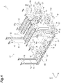
FIG. 1] FIG. 1 is a perspective view illustrating a storage shelf according to one embodiment. - [
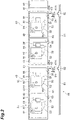
FIG. 2] FIG. 2 is a configuration schematic diagram of shelf modules included in the storage shelf inFIG. 1 . - [
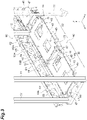
FIG. 3] FIG. 3 is a perspective view illustrating the shelf module bridged over the main unit. - [
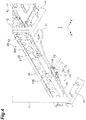
FIG. 4] FIG. 4 is a perspective view illustrating a state in which the shelf module bridged over the main unit is removed. - One suitable embodiment of the one aspect of the present invention will be described in detail below with reference to the drawings. It should be noted that, like or equivalent elements are designated by like reference signs in the description of the drawings, and duplicate description is omitted. Terms "X-direction," "Y-direction," and "Z-direction" are for convenience based on illustrated directions. It should be noted that, in
FIG. 1 , a purgegas supply facility 60 and a wiring facility 70 are omitted. - A storage shelf 1 illustrated in
FIG. 1 is disposed along atrack 5 of anoverhead traveling car 3 that constitutes a semiconductor transfer system in a semiconductor manufacturing plant, for example. The storage shelf 1 temporarily stores a container F such as FOUPs or reticle pods in which items to be stored such as semiconductor wafers or glass substrates are stored. The storage shelf 1 includes amain frame 10,first shelf modules 30, second shelf modules (shelf modules) 40, the purge gas supply facility 60 (refer toFIG. 2 ), and the wiring facility 70 (refer toFIG. 4 ). - As illustrated in
FIG. 1 andFIG. 3 , themain frame 10 is a member that suspends thefirst shelf module 30 and thesecond shelf module 40 from a ceiling. A plurality of themain frames 10 are arranged at equal intervals along the extension direction (X direction) of thetrack 5. - The
main frame 10 has a pair of first suspendingsections first shelf support 13, afirst connection 15, a pair of second suspendingsections second connections 16, andfall prevention fences 18. - The pair of first suspending
sections first shelf support 13 connects lower ends of the pair of firstsuspending sections first shelf support 13 extends along a short direction (Y direction) of thefirst shelf module 30 and supports thefirst shelf module 30 from below. Thefirst connection 15 is connected at both ends thereof to the pair of firstsuspending sections first shelf support 13. - The pair of second suspending
sections sections sections suspending sections second shelf support 14 connects one of the pair of firstsuspending sections suspending sections second shelf support 14 extends along the short direction (Y direction) of thesecond shelf module 40 and supports thesecond shelf module 40 from below. Thesecond connection 16 is connected to the first suspendingsection 11 at one end thereof and to the second suspendingsection 12 at the other end thereof, and extends parallel (Y direction) to thesecond shelf support 14. - The
fall prevention fence 18 is a flat, straddle member that is hung between adjacent ones of the first suspendingsections suspending sections fall prevention fences 18 are disposed to sandwich the container F placed on thefirst shelf module 30 or thesecond shelf module 40 from sides of the container F (Y direction). In other words, thefall prevention fences 18 are disposed to prevent the container F placed on thefirst shelf module 30 or thesecond shelf module 40 from falling from thefirst shelf module 30 or thesecond shelf module 40. - The
first shelf module 30 is a member on which the container F is placed. Thefirst shelf module 30 is a unit that does not have any purge function, i.e., a unit that does not have any function to supply gas to the container F to be placed on thefirst shelf module 30. Thefirst shelf module 30 is hung between adjacent ones of the first shelf supports 13, 13 or between adjacent ones of the second shelf supports 14, 14. - The
first shelf module 30 has afirst shelf frame 31 and afirst shelf plate 33. Thefirst shelf frame 31 is hung between adjacent ones of the first shelf supports 13, 13 or between adjacent ones of the second shelf supports 14, 14 in the X direction. Thefirst shelf frame 31 is a substantially rectangular plate-shaped member in plan view from the Z direction. Thefirst shelf frame 31 is fixed to thefirst shelf support 13 or thesecond shelf support 14 by screws inserted from below into insertion holes in thefirst shelf support 13 or thesecond shelf support 14. Bolts and nuts may be used instead of the screws. - The
first shelf plate 33 is supported on an upper surface of thefirst shelf frame 31 via anelastic body 37. Thefirst shelf plate 33 is a substantially rectangular plate-shaped member in plan view from the Z direction. Examples of materials for theelastic body 37 include rubber material, silicone gel material, urethane gel, and a metal spring. Thefirst shelf plate 33 has a mounting surface on which the container F is placed, and the mounting surface is provided withpins 35. Each of thepins 35 protrudes upward from the mounting surface of thefirst shelf plate 33. Thepin 35 is disposed in a position corresponding to a positioning groove (not illustrated) on a bottom of the container F. - As illustrated in
FIG. 1 to FIG. 3 , thesecond shelf module 40 is a member on which the container F is placed. Thesecond shelf module 40 is a unit with a purge function, i.e., a unit that supplies gas to the container F to be placed on thesecond shelf module 40. Examples of the gas include nitrogen gas, dry air, and the like. Thesecond shelf module 40 is hung between adjacent ones of the second shelf supports 14, 14. - The
second shelf module 40 has a second shelf frame (base plate) 41, asecond shelf plate 43, and apurging facility 50. Thesecond shelf frame 41 is hung between adjacent ones of the second shelf supports 14, 14 in the X direction. Thesecond shelf frame 41 is a substantially rectangular plate-shaped member in plan view from the Z direction. - The
second shelf plate 43 is supported on the upper surface of thesecond shelf frame 41 via anelastic body 47. Examples of materials for theelastic body 47 include rubber material, silicone gel material, urethane gel, and a metal spring. Thesecond shelf plate 43 is a substantially rectangular plate-shaped member in plan view from the Z direction. The twosecond shelf plates 43 are arranged along the X direction on thesecond shelf frame 41. That is, thesecond shelf module 40 has a plurality ofsupply nozzles 51 and a plurality of mass flow controllers (MFCs) 55. - The
second shelf plate 43 has a mounting surface on which the container F is placed, and threepins 45 are provided for the single mounting surface. Each of thepins 45 protrudes upward from the mounting surface of thesecond shelf plate 43. Thepin 45 is disposed in a position corresponding to a positioning groove (not illustrated) on the bottom of the container F. - The purging
facility 50 has thesupply nozzle 51, afirst pipe 52, afilter section 53, asecond pipe 54, theMFC 55, athird pipe 56, and adetection sensor 59. - The
supply nozzle 51 is a nozzle that supplies gas to the interior of the container F. Thesupply nozzle 51 protrudes upward from the mounting surface of thesecond shelf plate 43 and is connected to an introduction hole on the bottom of the container F when the container F is placed on thesupply nozzle 51. Thefirst pipe 52 is a tubular member that connects thesupply nozzle 51 to thefilter section 53. Thefilter section 53 is a member housing a filter that removes foreign matter contained in gas that passes through thefilter section 53, removing foreign matter contained in gas supplied from a supply source of the gas through themain pipe 61. Thefilter section 53 is fixed to thesecond shelf frame 41 by a suitable member. Thesecond pipe 54 is a tubular member that connects thefilter section 53 to theMFC 55. - The
MFC 55 is a device that measures a flow rate of the gas supplied from themain pipe 61 and controls the flow rate. TheMFC 55 is controlled by the main controller, which is not illustrated. TheMFC 55 is provided on each of thesecond shelf plates 43. TheMFC 55 is connected to amain wiring 71, which is connected to the main controller via amodule wiring 73. - The main controller controls the
MFC 55 to supply a predetermined flow rate of the gas to the container F when the container F is detected by thedetection sensor 59, and controls theMFC 55 not to supply the gas to the container F when the container F is not detected by thedetection sensor 59. TheMFC 55 is fixed to an underside of thesecond shelf frame 41 by a suitable method. - The
third pipe 56 is a tubular member that connects theMFC 55 to asecond branch 65. An end of thethird pipe 56 that is connected to thesecond branch 65 is provided with apipe connector 65A that enables connection to thesecond branch 65, which is described in detail later. - The
detection sensor 59 detects whether the container F is placed on thesecond shelf plate 43. Thedetection sensor 59 is provided on the mounting surface of thesecond shelf plate 43. The 59 detection sensor is controlled by the main controller, which is not illustrated. Thedetection sensor 59 is connected to themain wiring 71, which is connected to the main controller via themodule wiring 73. - As illustrated in
FIG. 2 andFIG. 3 , the purgegas supply facility 60 has themain pipe 61, afirst branch 62, arelay pipe 62A, amodule pipe 63, an open/close valve 64, and thesecond branch 65. - The
main pipe 61 is connected to the supply source of the gas to be supplied to thepurging facility 50. Themain pipe 61 is a tubular member formed from metal, such as stainless steel, or from resin, such as fluorocarbon resin. Themain pipe 61 is attached, via a mountingmember 18A, to thefall prevention fence 18, which is hung between adjacent ones of the second suspendingsections - The
first branch 62 is provided in themain pipe 61 to branch the flow path from themain pipe 61. In the present embodiment, thefirst branches 62 are provided, the number of which corresponds to the number of thesecond shelf modules 40 with thepurging facilities 50. One end of therelay pipe 62A is connected to thefirst branch 62. The other end of therelay pipe 62A is connected to themodule pipe 63 via the open/close valve 64. Therelay pipe 62A relays the purge gas flowing in themain pipe 61 to themodule pipe 63. - The open/
close valve 64 opens and closes the flow path from therelay pipe 62A to themodule pipe 63. In other words, themodule pipe 63 is connected to thefirst branch 62 via the open/close valve 64 that opens and closes the flow path. Themodule pipe 63 and the open/close valve 64 are supported by thefall prevention fence 18, which is hung between the adjacent ones of the second suspendingsections bracket 18B. - The
second branch 65 is provided in themodule pipe 63 to branch the flow path from themodule pipe 63. As described above, thesecond shelf module 40 is provided with the plurality ofMFCs 55. Each of theMFCs 55 is connected to themodule pipe 63 via thesecond branch 65. The end of thesecond branch 65, which is disposed at the most downstream section in themodule pipe 63, is sealed so that the purge gas flows only to theMFC 55. In the present embodiment, themodule pipe 63 is provided with thesecond branches 65, the number of which corresponds to the number of theMFCs 55. Each of theMFCs 55 is connected to thesecond branch 65 via thethird pipe 56. - In the above-described embodiment, an example is described in which the
second branches 65 are provided, the number of which corresponds to the number ofMFCs 55, however, thesecond branches 65 the number of which is one less than the number ofMFCs 55 may be disposed. In this case, thesecond branch 65, disposed at the most downstream section in themodule pipe 63, is connected to the twoMFCs 55 via the twothird pipes 56. - As illustrated in
FIG. 4 , the wiring facility 70 has themain wiring 71, athird branch 72, and themodule wiring 73. - The
main wiring 71 is connected to the main controller that intensively controls thepurging facilities 50. Themain wiring 71 is supported by thefall prevention fence 18, which is hung between adjacent ones of the second suspendingsections bracket 18B. The main controller may be fixed to part of the storage shelf 1, for example, or may be provided away from the storage shelf 1 via a relay device or the like. - The
third branch 72 is provided in themain wiring 71, electrically branches from themain wiring 71, and detachably connects themodule wiring 73. In the present embodiment, thethird branches 72 are provided, the number of which is the same as the number of MFCs 55 (or the detection sensors 59) provided in thesecond shelf module 40. Each of the MFCs 55 (or the detection sensors 59) is connected to themodule wiring 73 via thethird branch 72. - The
module wiring 73 connects thethird branch 72 to theMFC 55 and also connects thethird branch 72 to thedetection sensor 59. Themodule wiring 73 is connected to thethird branch 72 of themain wiring 71. At the end of themodule wiring 73 that is connected to thethird branch 72, awiring connector 73A is provided that enables connection to thethird branch 72. It should be noted that themain wiring 71 and themodule wiring 73 have a function not only as communication lines for exchanging information, but also as power lines for exchanging power. - Next, procedure for removing the
second shelf module 40 from themain frame 10 is described. The operator first closes the open/close valve 64 illustrated inFIG. 2 andFIG. 3 . The operator then releases the bolts that fasten thesecond shelf frame 41, which is bridged over thesecond shelf support 14, and thesecond shelf support 14. The operator then removes themodule pipe 63 from the open/close valve 64 or removes thethird pipe 56 from thesecond branch 65. This completes a process of removing thesecond shelf module 40 from themain frame 10. - Next, the procedure for attaching the
second shelf module 40 of the present embodiment to themain frame 10 will be described. The operator bridges thesecond shelf module 40 to thesecond shelf support 14, and connects themodule pipe 63 to the open/close valve 64 or connects thethird pipe 56 to thesecond branch 65. Next, the operator fastens thesecond shelf frame 41 to thesecond shelf support 14 with the bolts. The operator then opens the open/close valve 64 and leaves it open for a while. This completes the aging of thesecond shelf module 40 that has been replaced. In other words, installation of thesecond shelf module 40 on themain frame 10 is completed. - Functional effects of the storage shelf 1 according to the above-described embodiment will be described. In the storage shelf 1 of the above-described embodiment, when replacing the
second shelf module 40, the operator does not need to shut off the purge gas flowing through themain pipe 61 or seal the removal portion (in the present embodiment, the open/close valve 64 from which themodule pipe 63 is removed or thesecond branch 65 from which thethird pipe 56 is removed), but only needs to remove themodule pipe 63 from the open/close valve 64 or remove thethird pipe 56 from thesecond branch 65 after performing a simple task of closing the open/close valve 64. Moreover, in the storage shelf 1 with this configuration, since the open/close valve 64 is closed to prevent foreign matter from entering themain pipe 61, the operator does not need to perform aging for themain pipe 61, which is performed in the above-described conventional storage shelf, but only needs to perform aging for themodule pipe 63. This means that the operator does not need to remove the containers F disposed in the othersecond shelf module 40 during the aging, and after connecting themodule pipe 63, only needs to open the open/close valve 64 and leave it open for a while. Thus, the storage shelf 1 with this configuration can reduce the workload the operator has when replacing thesecond shelf module 40 or the components that are provided in the second shelf module 40 (e.g., thesupply nozzle 51 or theMFC 55, or the like). - In the configuration of the storage shelf 1 of the above-described embodiment, as illustrated in
FIG. 2 , even when each of thesecond shelf modules 40 is provided with a plurality of thesupply nozzles 51 and theMFCs 55, the operator, after performing the simple task of closing the open/close valve 64, only needs to remove themodule pipe 63 from the open/close valve 64 or remove thethird pipe 56 from thesecond branch 65, and after connecting themodule pipe 63, the operator only needs to open the open/close valve 64 to leave it open for a while. Thus, the storage shelf 1 with this configuration can reduce the workload the operator has when replacing thesecond shelf module 40 or the components that are provided in thesecond shelf module 40. - In the above-described configuration of the storage shelf 1, as illustrated in
FIG. 3 , themodule pipe 63 and the open/close valve 64 are supported by thefall prevention fence 18, which is hung between the adjacent ones of the second suspendingsections main frame 10, via thebracket 18B. In this configuration, after disconnecting the connection between themodule pipe 63 and the open/close valve 64, the open/close valve 64 remains on thebracket 18B provided on thefall prevention fence 18 of themain frame 10, and thus the operator can easily remove only thesecond shelf module 40. Moreover, in this configuration, after disconnecting the connection between thesecond branch 65 and thethird pipe 56, the open/close valve 64 and themodule pipe 63 remain on thebracket 18B provided on thefall prevention fence 18 of themain frame 10, and thus the operator can easily remove only thesecond shelf module 40. - In the configuration of the storage shelf 1 of the above-described embodiment, the operator can easily remove the
second shelf module 40 by a simply task of removing themodule wiring 73 from thethird branch 72. - Although one embodiment has been described above, one aspect of the present invention is not necessarily limited to the above-described embodiment, and various modifications may be made without departing from the gist of the invention.
- In the above-described embodiment, although an example is described in which the two second shelf plates 43 (i.e., a place to place the container F where the
supply nozzle 51 and theMFC 55 are provided) are provided on themain frame 10 via thesecond shelf frame 41, themain frame 10 may have a configuration in which only the singlesecond shelf plate 43 is provided on themain frame 10 via thesecond shelf frame 41. In a configuration according to this modification, it is not necessary to provide thesecond branch 65 in themodule pipe 63, and themodule pipe 63 may be directly connected to theMFC 55. As in the above-described embodiment, the singlesecond branch 65 may be provided in themodule pipe 63 to connect one of the branches to theMFC 55 and the other of the branches may be sealed. - In the above-described embodiment and modifications, although an example is described in which each of the two
second shelf plates 43 is provided with thesupply nozzles 51 and theMFC 55, the purgingfacility 50 such as thesupply nozzle 51 and theMFC 55 may be provided directly on thesecond shelf frame 41. - In the above-described embodiment and modifications, although the example is described in which the
second shelf frame 41 that is bridged over themain frame 10, thesecond shelf plate 43 may be removed from thesecond shelf frame 41. Even in this case, the same effects as in the above-described embodiment and modifications can be obtained. Thesecond shelf plate 43 in this case functions as a base plate attached to themain frame 10 via thesecond shelf frame 41. - In the above-described embodiment and modifications, although an example is described in which the
second shelf module 40 is detachably provided in thesecond shelf support 14 that connects the first suspendingsection 11 to the lower end of the second suspendingsection 12, thesecond shelf module 40 may be detachably installed in thefirst shelf support 13. - The above-described embodiment and modifications, although an example is described in which an upper end of each of the first suspending
section 11 and the second suspendingsection 12 is fixed to a fixed part such as a ceiling, but the present invention is not limited thereto. For example, the respective upper ends of the first suspendingsection 11 and the second suspendingsection 12 may be fixed to a raceway or the like that allows each of the upper ends thereof to be able to slide by being unfastened. - In the above-described embodiment and modifications, although an example is described in which the
module pipe 63 and the open/close valve 64 are supported by thefall prevention fence 18 of themain frame 10, they may be supported in a state of bridging over the first suspendingsection 11 or the second suspendingsection 12. -
- 1
- Storage shelf
- 10
- Main frame
- 18
- Fall prevention fence (straddle member)
- 30
- First shelf module
- 31
- First shelf frame
- 33
- First shelf plate
- 40
- Second shelf module
- 41
- Second shelf frame (base plate)
- 43
- Second shelf plate
- 50
- Purging facility
- 51
- Supply nozzle
- 55
- MFC (mass flow controller)
- 59
- Detection sensor
- 60
- Purge gas supply facility
- 61
- Main pipe
- 62
- First branch
- 62A
- Relay pipe
- 63
- Module pipe
- 64
- Open/close valve
- 65
- Second branch
- 70
- Wiring facility
- 71
- Main wiring
- 72
- Third branch
- 73
- Module wiring
- F
- Container.
Claims (5)
- A storage shelf comprising:a main frame;a plurality of shelf modules each having a base plate detachably provided on the main frame, and a supply nozzle provided on the base plate;a main pipe through which purge gas supplied from a supply source flows; anda first branch that is provided in the main pipe and branches a flow path from the main pipe, whereinthe shelf modules are each provided with a mass flow controller configured to adjust the flow rate of the purge gas supplied to the supply nozzle,the first branch is connected to a module pipe via an open/close valve for opening/closing the flow path, andthe mass flow controller is connected to the module pipe.
- The storage shelf according to claim 1, whereinthe shelf module is provided with a plurality of the supply nozzles and a plurality of the mass flow controllers corresponding to the respective supply nozzles,the storage shelf further includes a second branch that is provided in the module pipe and branches the flow path from the module pipe, andeach of the mass flow controllers is connected to the module pipe via the second branch.
- The storage shelf according to claim 1 or 2, wherein the module pipe and/or the open/close valve is supported by the main frame.
- The storage shelf according to any one of claims 1 to 3, wherein the main frame is a suspended member that is suspended from a ceiling or from a member fixed to the ceiling and is arranged in one direction,the base plate is bridged over the main frame arranged in the one direction, andthe module pipe and/or the open/close valve is supported by a straddle member that is a different member from the base plate and that is bridged over the main frame arranged in the one direction.
- The storage shelf according to any one of claims 1 to 4, further comprising;a main wiring that is connected to a main controller or a power supply;a module wiring that is connected to the mass flow controller or the supply nozzle provided in the shelf module and that is connected to a detection sensor configured to detect a container; anda third branch that is provided in the main wiring, electrically branches from the main wiring, and detachably connects the module wiring.
Applications Claiming Priority (2)
| Application Number | Priority Date | Filing Date | Title |
|---|---|---|---|
| JP2020037929 | 2020-03-05 | ||
| PCT/JP2021/001632 WO2021176865A1 (en) | 2020-03-05 | 2021-01-19 | Storage shelf |
Publications (2)
| Publication Number | Publication Date |
|---|---|
| EP4112506A1 true EP4112506A1 (en) | 2023-01-04 |
| EP4112506A4 EP4112506A4 (en) | 2024-04-03 |
Family
ID=77613098
Family Applications (1)
| Application Number | Title | Priority Date | Filing Date |
|---|---|---|---|
| EP21763225.6A Pending EP4112506A4 (en) | 2020-03-05 | 2021-01-19 | STORAGE SHELF |
Country Status (8)
| Country | Link |
|---|---|
| US (1) | US12322624B2 (en) |
| EP (1) | EP4112506A4 (en) |
| JP (1) | JP7231106B2 (en) |
| KR (1) | KR102764783B1 (en) |
| CN (1) | CN115175867B (en) |
| IL (1) | IL295872B2 (en) |
| TW (1) | TWI854103B (en) |
| WO (1) | WO2021176865A1 (en) |
Families Citing this family (1)
| Publication number | Priority date | Publication date | Assignee | Title |
|---|---|---|---|---|
| JP7529039B2 (en) * | 2020-11-12 | 2024-08-06 | 村田機械株式会社 | Storage shelf |
Family Cites Families (18)
| Publication number | Priority date | Publication date | Assignee | Title |
|---|---|---|---|---|
| US5307568A (en) * | 1991-09-09 | 1994-05-03 | Tokyo Electron Limited | Gas supply system |
| JP4144970B2 (en) * | 1999-05-18 | 2008-09-03 | 株式会社日立国際電気 | Semiconductor manufacturing method and apparatus |
| US6506009B1 (en) * | 2000-03-16 | 2003-01-14 | Applied Materials, Inc. | Apparatus for storing and moving a cassette |
| CN103086108A (en) * | 2011-11-08 | 2013-05-08 | 南通金恒不锈钢制管有限公司 | Improved goods shelf |
| WO2014030421A1 (en) * | 2012-08-21 | 2014-02-27 | 村田機械株式会社 | Stocker provided with purging functionality, stocker unit, and method for supplying cleaning gas |
| KR101418812B1 (en) | 2012-10-31 | 2014-07-16 | 크린팩토메이션 주식회사 | Apparatus for stocking and purging wafer at ceiling |
| US9257320B2 (en) * | 2013-06-05 | 2016-02-09 | GlobalFoundries, Inc. | Wafer carrier purge apparatuses, automated mechanical handling systems including the same, and methods of handling a wafer carrier during integrated circuit fabrication |
| JP5892113B2 (en) * | 2013-06-26 | 2016-03-23 | 株式会社ダイフク | Goods storage facility |
| US10325794B2 (en) * | 2014-04-28 | 2019-06-18 | Murata Machinery, Ltd. | Purge device and purge method |
| US9875921B2 (en) | 2015-05-07 | 2018-01-23 | Fabmatics Gmbh | Flexible purge management system |
| CN106477229A (en) * | 2015-08-26 | 2017-03-08 | 衡阳华瑞电气有限公司 | A kind of U-tube rack |
| JP6414525B2 (en) | 2015-09-02 | 2018-10-31 | 株式会社ダイフク | Storage facilities |
| JP6579067B2 (en) * | 2016-09-09 | 2019-09-25 | 株式会社ダイフク | Flow measuring device and flow measuring system |
| EP3584827B1 (en) | 2017-02-20 | 2022-02-16 | Murata Machinery, Ltd. | Purge stocker |
| JP6856015B2 (en) | 2017-12-20 | 2021-04-14 | 株式会社ダイフク | Storage equipment |
| WO2020017137A1 (en) | 2018-07-20 | 2020-01-23 | 村田機械株式会社 | Storage shelf, and method for installing storage shelf |
| KR102190920B1 (en) * | 2018-08-16 | 2020-12-16 | 세메스 주식회사 | Purge apparatus and purge method |
| JP7090513B2 (en) * | 2018-09-06 | 2022-06-24 | 東京エレクトロン株式会社 | Board processing equipment and purging method |
-
2021
- 2021-01-19 KR KR1020227021400A patent/KR102764783B1/en active Active
- 2021-01-19 US US17/908,145 patent/US12322624B2/en active Active
- 2021-01-19 CN CN202180016504.0A patent/CN115175867B/en active Active
- 2021-01-19 EP EP21763225.6A patent/EP4112506A4/en active Pending
- 2021-01-19 WO PCT/JP2021/001632 patent/WO2021176865A1/en not_active Ceased
- 2021-01-19 IL IL295872A patent/IL295872B2/en unknown
- 2021-01-19 JP JP2022505012A patent/JP7231106B2/en active Active
- 2021-03-02 TW TW110107230A patent/TWI854103B/en active
Also Published As
| Publication number | Publication date |
|---|---|
| KR20220103789A (en) | 2022-07-22 |
| US20230134774A1 (en) | 2023-05-04 |
| IL295872A (en) | 2022-10-01 |
| US12322624B2 (en) | 2025-06-03 |
| CN115175867B (en) | 2024-06-18 |
| TW202139334A (en) | 2021-10-16 |
| TWI854103B (en) | 2024-09-01 |
| CN115175867A (en) | 2022-10-11 |
| IL295872B2 (en) | 2025-11-01 |
| KR102764783B1 (en) | 2025-02-11 |
| JPWO2021176865A1 (en) | 2021-09-10 |
| IL295872B1 (en) | 2025-07-01 |
| WO2021176865A1 (en) | 2021-09-10 |
| JP7231106B2 (en) | 2023-03-01 |
| EP4112506A4 (en) | 2024-04-03 |
Similar Documents
| Publication | Publication Date | Title |
|---|---|---|
| US11631603B2 (en) | Storage shelf, and method for installing storage shelf | |
| US20230062287A1 (en) | Semiconductor stocker systems and methods | |
| KR101433729B1 (en) | Workpiece stocker with circular configuration | |
| US20040069226A1 (en) | Substrate processing method and substrate processing system | |
| CA2307663A1 (en) | Gas panel | |
| CN103171843A (en) | Goods storage equipment and goods storage method | |
| US9645000B2 (en) | Measurement device and purge gas flow rate measuring method | |
| US12322624B2 (en) | Storage shelf | |
| TW201418121A (en) | Storage device with clarification function, hopper unit and supply method of clean gas | |
| TWI715802B (en) | Flow measuring device and flow measuring system | |
| JP6217281B2 (en) | Automatic warehouse and gas supply method | |
| CN103171854A (en) | Article keeping apparatus and article keeping method | |
| KR20180092288A (en) | Flow rate measurement system | |
| US11056357B2 (en) | Substrate processing apparatus and substrate processing apparatus assembling method | |
| KR100549948B1 (en) | Clean System of Semiconductor Manufacturing Equipment | |
| US20210257239A1 (en) | Storage shelf | |
| KR101398440B1 (en) | Foup purge apparatus and substrate processing apparatus comprising the same | |
| KR20190070310A (en) | Apparatus for changing chemical filter automatically | |
| KR101999542B1 (en) | apparatus for changing chemical filter automatically | |
| TWI899511B (en) | Purification system | |
| CN113764320A (en) | Substrate processing equipment, reactor mover, and maintenance method | |
| TW202235339A (en) | storage rack | |
| CN221472865U (en) | Material box purification device and mechanism | |
| JPS60207337A (en) | Module plasma reactor having local contamination gas | |
| KR20100059358A (en) | Exhaust unit, and substrate processing apparatus and method using same |
Legal Events
| Date | Code | Title | Description |
|---|---|---|---|
| STAA | Information on the status of an ep patent application or granted ep patent |
Free format text: STATUS: THE INTERNATIONAL PUBLICATION HAS BEEN MADE |
|
| PUAI | Public reference made under article 153(3) epc to a published international application that has entered the european phase |
Free format text: ORIGINAL CODE: 0009012 |
|
| STAA | Information on the status of an ep patent application or granted ep patent |
Free format text: STATUS: REQUEST FOR EXAMINATION WAS MADE |
|
| 17P | Request for examination filed |
Effective date: 20220930 |
|
| AK | Designated contracting states |
Kind code of ref document: A1 Designated state(s): AL AT BE BG CH CY CZ DE DK EE ES FI FR GB GR HR HU IE IS IT LI LT LU LV MC MK MT NL NO PL PT RO RS SE SI SK SM TR |
|
| DAV | Request for validation of the european patent (deleted) | ||
| DAX | Request for extension of the european patent (deleted) | ||
| REG | Reference to a national code |
Ref country code: DE Ref legal event code: R079 Free format text: PREVIOUS MAIN CLASS: B65G0001140000 Ipc: H01L0021673000 |
|
| A4 | Supplementary search report drawn up and despatched |
Effective date: 20240304 |
|
| RIC1 | Information provided on ipc code assigned before grant |
Ipc: B65G 1/02 20060101ALI20240227BHEP Ipc: H01L 21/677 20060101ALI20240227BHEP Ipc: H01L 21/673 20060101AFI20240227BHEP |
|
| REG | Reference to a national code |
Ref country code: DE Ref legal event code: R079 Free format text: PREVIOUS MAIN CLASS: H01L0021673000 Ipc: B65G0001020000 |
|
| RIC1 | Information provided on ipc code assigned before grant |
Ipc: B65G 1/02 20060101AFI20260406BHEP Ipc: H10P 72/30 20260101ALI20260406BHEP Ipc: H10P 72/10 20260101ALI20260406BHEP |