EP4112485A1 - Pack for smoking products - Google Patents
Pack for smoking products Download PDFInfo
- Publication number
- EP4112485A1 EP4112485A1 EP22180483.4A EP22180483A EP4112485A1 EP 4112485 A1 EP4112485 A1 EP 4112485A1 EP 22180483 A EP22180483 A EP 22180483A EP 4112485 A1 EP4112485 A1 EP 4112485A1
- Authority
- EP
- European Patent Office
- Prior art keywords
- packets
- group
- adhesive tape
- lateral surface
- advance
- Prior art date
- Legal status (The legal status is an assumption and is not a legal conclusion. Google has not performed a legal analysis and makes no representation as to the accuracy of the status listed.)
- Pending
Links
Images


Classifications
-
- B—PERFORMING OPERATIONS; TRANSPORTING
- B65—CONVEYING; PACKING; STORING; HANDLING THIN OR FILAMENTARY MATERIAL
- B65B—MACHINES, APPARATUS OR DEVICES FOR, OR METHODS OF, PACKAGING ARTICLES OR MATERIALS; UNPACKING
- B65B19/00—Packaging rod-shaped or tubular articles susceptible to damage by abrasion or pressure, e.g. cigarettes, cigars, macaroni, spaghetti, drinking straws or welding electrodes
- B65B19/02—Packaging cigarettes
-
- B—PERFORMING OPERATIONS; TRANSPORTING
- B65—CONVEYING; PACKING; STORING; HANDLING THIN OR FILAMENTARY MATERIAL
- B65B—MACHINES, APPARATUS OR DEVICES FOR, OR METHODS OF, PACKAGING ARTICLES OR MATERIALS; UNPACKING
- B65B13/00—Bundling articles
- B65B13/02—Applying and securing binding material around articles or groups of articles, e.g. using strings, wires, strips, bands or tapes
- B65B13/04—Applying and securing binding material around articles or groups of articles, e.g. using strings, wires, strips, bands or tapes with means for guiding the binding material around the articles prior to severing from supply
-
- B—PERFORMING OPERATIONS; TRANSPORTING
- B65—CONVEYING; PACKING; STORING; HANDLING THIN OR FILAMENTARY MATERIAL
- B65B—MACHINES, APPARATUS OR DEVICES FOR, OR METHODS OF, PACKAGING ARTICLES OR MATERIALS; UNPACKING
- B65B11/00—Wrapping, e.g. partially or wholly enclosing, articles or quantities of material, in strips, sheets or blanks, of flexible material
- B65B11/06—Wrapping articles, or quantities of material, by conveying wrapper and contents in common defined paths
- B65B11/08—Wrapping articles, or quantities of material, by conveying wrapper and contents in common defined paths in a single straight path
- B65B11/10—Wrapping articles, or quantities of material, by conveying wrapper and contents in common defined paths in a single straight path to fold the wrappers in tubular form about contents
-
- B—PERFORMING OPERATIONS; TRANSPORTING
- B65—CONVEYING; PACKING; STORING; HANDLING THIN OR FILAMENTARY MATERIAL
- B65B—MACHINES, APPARATUS OR DEVICES FOR, OR METHODS OF, PACKAGING ARTICLES OR MATERIALS; UNPACKING
- B65B13/00—Bundling articles
- B65B13/02—Applying and securing binding material around articles or groups of articles, e.g. using strings, wires, strips, bands or tapes
-
- B—PERFORMING OPERATIONS; TRANSPORTING
- B65—CONVEYING; PACKING; STORING; HANDLING THIN OR FILAMENTARY MATERIAL
- B65B—MACHINES, APPARATUS OR DEVICES FOR, OR METHODS OF, PACKAGING ARTICLES OR MATERIALS; UNPACKING
- B65B13/00—Bundling articles
- B65B13/18—Details of, or auxiliary devices used in, bundling machines or bundling tools
- B65B13/24—Securing ends of binding material
- B65B13/32—Securing ends of binding material by welding, soldering, or heat-sealing; by applying adhesive
-
- B—PERFORMING OPERATIONS; TRANSPORTING
- B65—CONVEYING; PACKING; STORING; HANDLING THIN OR FILAMENTARY MATERIAL
- B65B—MACHINES, APPARATUS OR DEVICES FOR, OR METHODS OF, PACKAGING ARTICLES OR MATERIALS; UNPACKING
- B65B17/00—Other machines, apparatus, or methods for packaging articles or materials
- B65B17/02—Joining articles, e.g. cans, directly to each other for convenience of storage, transport, or handling
- B65B17/025—Joining articles, e.g. cans, directly to each other for convenience of storage, transport, or handling the articles being joined by a top carrier element
-
- B—PERFORMING OPERATIONS; TRANSPORTING
- B65—CONVEYING; PACKING; STORING; HANDLING THIN OR FILAMENTARY MATERIAL
- B65B—MACHINES, APPARATUS OR DEVICES FOR, OR METHODS OF, PACKAGING ARTICLES OR MATERIALS; UNPACKING
- B65B27/00—Bundling particular articles presenting special problems using string, wire, or narrow tape or band; Baling fibrous material, e.g. peat, not otherwise provided for
-
- B—PERFORMING OPERATIONS; TRANSPORTING
- B65—CONVEYING; PACKING; STORING; HANDLING THIN OR FILAMENTARY MATERIAL
- B65B—MACHINES, APPARATUS OR DEVICES FOR, OR METHODS OF, PACKAGING ARTICLES OR MATERIALS; UNPACKING
- B65B35/00—Supplying, feeding, arranging or orientating articles to be packaged
- B65B35/30—Arranging and feeding articles in groups
- B65B35/40—Arranging and feeding articles in groups by reciprocating or oscillatory pushers
-
- B—PERFORMING OPERATIONS; TRANSPORTING
- B65—CONVEYING; PACKING; STORING; HANDLING THIN OR FILAMENTARY MATERIAL
- B65B—MACHINES, APPARATUS OR DEVICES FOR, OR METHODS OF, PACKAGING ARTICLES OR MATERIALS; UNPACKING
- B65B51/00—Devices for, or methods of, sealing or securing package folds or closures; Devices for gathering or twisting wrappers, or necks of bags
- B65B51/04—Applying separate sealing or securing members, e.g. clips
- B65B51/06—Applying adhesive tape
-
- B—PERFORMING OPERATIONS; TRANSPORTING
- B65—CONVEYING; PACKING; STORING; HANDLING THIN OR FILAMENTARY MATERIAL
- B65D—CONTAINERS FOR STORAGE OR TRANSPORT OF ARTICLES OR MATERIALS, e.g. BAGS, BARRELS, BOTTLES, BOXES, CANS, CARTONS, CRATES, DRUMS, JARS, TANKS, HOPPERS, FORWARDING CONTAINERS; ACCESSORIES, CLOSURES, OR FITTINGS THEREFOR; PACKAGING ELEMENTS; PACKAGES
- B65D85/00—Containers, packaging elements or packages, specially adapted for particular articles or materials
- B65D85/07—Containers, packaging elements or packages, specially adapted for particular articles or materials for compressible or flexible articles
- B65D85/08—Containers, packaging elements or packages, specially adapted for particular articles or materials for compressible or flexible articles rod-shaped or tubular
- B65D85/10—Containers, packaging elements or packages, specially adapted for particular articles or materials for compressible or flexible articles rod-shaped or tubular for cigarettes
- B65D85/1072—Bundle of cigarette packs
-
- B—PERFORMING OPERATIONS; TRANSPORTING
- B65—CONVEYING; PACKING; STORING; HANDLING THIN OR FILAMENTARY MATERIAL
- B65B—MACHINES, APPARATUS OR DEVICES FOR, OR METHODS OF, PACKAGING ARTICLES OR MATERIALS; UNPACKING
- B65B13/00—Bundling articles
- B65B13/02—Applying and securing binding material around articles or groups of articles, e.g. using strings, wires, strips, bands or tapes
- B65B13/04—Applying and securing binding material around articles or groups of articles, e.g. using strings, wires, strips, bands or tapes with means for guiding the binding material around the articles prior to severing from supply
- B65B13/14—Pairs of carriers or guides movable around opposite sides of the articles
Definitions
- the present invention relates to a novel pack for smoking products.
- the pack described here belongs to the type of packs that comprise an ordered group of packets containing smoking products, positioned in contact with each other.
- a widespread known solution for packs of this type provides a container made of cardboard, in which an ordered group of packets is received, and an outer wrapper of plastic material which is wrapped completely round the container.
- the document WO2014 053515 A1 illustrates a solution in which a sheet of heat shrink film wraps the group of packets and presses them against each other to hold them together.
- the document DE29518315U1 illustrates a pack composed of a base and an upper cover, between which the group of packets is received, and a series of bands for holding the base and the upper cover together.
- the present invention is also intended to resolve the problem of reducing the amount of material used, by presenting a solution which is an improvement on the known solutions discussed above in various respects, including a further reduction in the amount of material used and a simplification of the corresponding production method.
- the present invention relates in a general way to a packaging method according to Claim 1.
- the present invention also relates to a machine according to Claim 6 and a pack according to Claim 9.
- the pack described here is a pack for smoking products, and, in particular, belongs to the type of packs comprising an ordered group of packets containing smoking products and positioned in contact with each other.
- the pack described here has been devised specifically for making multiple packs of cigarette packets, and reference is made below to this specific application. In all cases, the teachings provided here may also be used for making other types of packs.
- this shows two examples of groups of packets G that are commonly provided in multiple packs of cigarette packets
- the combination of the packets P forms a parallelepiped.
- the sides or lateral surfaces Gi of the parallelepiped are defined by the corresponding faces of all the packets that make up the group.
- the sides Gii are defined by the corresponding faces of a subset of packets of the group G.
- the group of packets G of view a) is formed by pairs of packets side by side and in contact, which are arranged in series and in mutual contact; in the illustrated example, the packets of a single pair are in contact on their respective major faces, although they could alternatively be placed in contact on their respective minor faces.
- the group of packets G of view b is formed by individual packets arranged in series and in mutual contact; in the illustrated example, the individual packets are in contact on their respective major faces, although they could alternatively be placed in contact on their respective minor faces.
- the lateral surface in question is unique and is formed by the four sides Gii of the group of packets G (these sides are denoted below by the references G1, G2, G3, G4 respectively).
- the surface S 1 extends around a reference axis I1 of the group of packets G.
- the pack 10 comprises a group G of packets P having a configuration corresponding to that shown in drawing A of Figure 3 .
- the pack 10 comprises an adhesive tape 2, applied to the closed lateral surface S1 of the group of packets G, which is wrapped completely around the latter, and which, on its own, holds together the packets P of the group.
- the pack 10 further comprises a second adhesive tape 4, also applied to the closed lateral surface S1 and wrapped completely around it. Even more preferably, the adhesive tape 4 extends parallel to the first adhesive tape 2.
- the pack described here is formed by the packets P and, additionally, the tape 2 or the tapes 2 and 4 only.
- the tape 2 and/or the tape 4 have respective opposite end tabs 2A and 4A that are superimposed on each other. Even more preferably, the opposite tabs 2A, 4A are superimposed over a length equal to at least half of the dimension of the group of packets G in the same direction.
- the tape 2 and/or the tape 4 have a width of less than 10 mm.
- the tapes 2, 4 are made of polymer material, even more preferably transparent or at least translucent polymer material, so that the underlying areas of the closed lateral surface S 1 are kept visible.
- the tapes 2, 4 are made of polypropylene.
- the inner sides of the two tapes are coated with a layer of adhesive material. This material may be of a known type commonly used in the relevant technical field.
- the solution described here also relates to a method for making a pack of the aforementioned type, and a machine for the implementation of said method.
- the method described here provides for unwinding the adhesive tape 2 or adhesive tapes 2, 4 from a reel and applying it/them to the closed lateral surface S1 of the group of packets G and completely around the latter, to hold the packets of the group together solely by means of the adhesive tape or the two adhesive tapes.
- the machine described here provides a unit for moving the group of packets G and a unit for applying the adhesive tape 2 or the adhesive tapes 2, 4 to the closed lateral surface S1 of the group of packets G.
- Figures 2A to 2H show successive steps of a preferred embodiment of the method described here, implemented by a preferred embodiment of the packaging machine described here.
- the method described here provides, in the first place, for causing the group of packets G to advance in a direction of advance K, in an arrangement in which the theoretical axis I1 of the group of packets G is orthogonal to the direction of advance K; the faces G1, G2, G3, G4, parallel to the theoretical axis I1, which form the closed lateral surface S 1, are arranged two by two, parallel to the direction of advance K or orthogonally thereto.
- the group of packets G is made to advance by means of a pushing member 108 (shown only in Figure 2A ).
- a continuous adhesive tape 200 is unwound from a reel and fed in a direction of feed Z, orthogonally to the direction of advance K and to the theoretical axis I1 of the group of packets G.
- the tape 200 is moved in the direction of feed Z by means of a driving member 101, which grips the end tab 200A of the tape 200 and draws it with itself in the feed direction Z ( Figure 2B ).
- the adhesive tape 200 is positioned in front of a first face G1 of the lateral surface S 1 of the group of packets G, with reference to the direction of advance K, and is interposed between the group of packets and a passage 104 which is defined by a first and a second stop element 102, 103, spaced apart from each other in the direction of feed Z.
- the tape 200 extends in the direction of feed Z beyond the passage 104 for a predetermined length, at least equal to the length of the face G2 of the lateral surface S1, preferably equal to about half of the perimeter of the lateral surface S1.
- the portion of the tape 200 that extends in the direction of feed Z is engaged by a suction plate 105 so as to be retained on a plane containing the same direction of feed Z.
- the suction plate 105 forms a single element that also defines the passage 104 and the two stop elements 102, 103 (the latter being identified by two opposite edges delimiting the passage 104).
- the plate 105 can be moved with an alternating motion in the direction of advance K, between a position shown in Figure 2C , in which its tape support surface 105A is coplanar with the direction of feed Z, and a position shown in Figure 2A , in which the surface 105A is displaced downstream with reference to the direction of advance K.
- the method provides for causing the group of packets G to advance in the direction of advance K, in order to bring it against the adhesive tape 200 positioned in front of it, and then in order to cause the group of packets G and the tape 200 engaged by it to advance through the passage 104 defined by the two stop elements 102, 103 ( Figures 2D and 2E ).
- the relative movement between the group of packets G and the two stop elements 102, 103 causes a gradual folding of the tape 200 into a U-shape against the opposite faces G2, G3 of the closed lateral surface S1 of the group of packets G.
- the relative movement between the group of packets G and the two stop elements 102, 103 is halted when the face G4 of the group of packets G becomes aligned with the direction of feed Z of the tape 200 ( Figure 2E ).
- the method provides for cutting the tape 200 by means of a cutting member 109, in a position along the direction of feed Z which is upstream of the plate 105, in order to separate the adhesive tape 2 that is partially wrapped around the group of packets G from the continuous tape 200 ( Figure 2F ).
- the position in which the tape 200 is cut must be such as to provide a sufficient length of the adhesive tape 2 to completely close the tape 2 around the group of packets G.
- the adhesive tape 2 separated from the continuous tape 200 is now folded in a U-shape around the group of packets G, and, preferably has two end tabs 2A extending beyond the faces G2, G3 of the group of packets and retained by corresponding portions of the plate 105 that are opposite each other with respect to the passage 104.
- the method described here then provides for folding the two tabs 2A of the tape 2 against the face G4 of the group of packets so as to close the tape 2 completely around said group of packets ( Figures 2G , 2H ).
- the length of the tabs 2A is preferably such that they are brought to a condition of mutual superimposition against the face G4 of the group of packets G.
- the plate 105 carries two folding members 107 which are positioned on opposite sides of the passage 104 and which are movable towards the inside of this passage and in the theoretical plane thereof, to engage the two opposite tabs 2A of the tape 2 and bring them against the face G4 of the group of packets.
- the two members 107 operate in succession so as to put the tabs 2A into the aforementioned condition of mutual superimposition ( Figures 2G and 2H ).
- the group of packets G and the plate 105 are positioned in such a way that the sliding plane of the two folding members 107 is aligned with the face G4 of the group of packets G ( Figure 2F ).
- the movement of each folding member 107 creates an action that presses the tabs 2A against the face G4 of the group of packets.
- this mutual position between the group of packets G and the plate 105 is reached as a result of their simultaneous movement in the direction of advance K.
- the plate 105 reaches the position of Figure 2A ; this is done in such a way that, while the two members 107 fold the tabs 2A of the tape, the driving member 101 is simultaneously free to move in the direction of feed Z in order to return to its position above the plate 105 to start a new cycle.
- a second continuous adhesive tape may be unwound from a further reel and applied to the group of packets G by the same means, and according to the same procedure, as those illustrated above.
- the same method illustrated above may also be used for applying at least one adhesive tape around the lateral surface S2 or S3 of the group of packets G illustrated in drawing B of Figure 3 ; in particular, the group of packets will be orientated with its theoretical axis 12 orthogonal to the directions K and Z in order to wrap the adhesive tape around the lateral surface S2, or with its theoretical axis 13 orthogonal to the directions K and Z in order to wrap the adhesive tape around the lateral surface S3.
- the packaging machine comprises a movement unit provided with the pushing member 108, and a tape application unit comprising the driving member 101, the suction plate 105 with the passage 104 and the two folding members 107, and the cutting member 109.
- the folding members of the projecting tabs of the tape may be entirely independent of the plate 105 and may be drivable with a motion which is rotary rather than translational.
- the plate 105 may be removed and its function may be performed by the driving member 101 in an operating condition in which it retains the tab 200A of the tape and supports the movement of the latter during the folding of the tape around the group of packets G.
Abstract
wherein the group of packets has a closed lateral surface (S1) around a theoretical axis (I1) of the group of packets, which delimits two opposite surfaces (Gi) of the group of packets, each of which surfaces is defined by the set of homologous surfaces of all the packets.
unwinding from a reel at least one adhesive tape (2, 4) and applying it to the closed lateral surface (S1) and completely around the latter, to hold the packets of the group together solely by means of the at least one adhesive tape (2, 4).
Description
- The present invention relates to a novel pack for smoking products.
- The pack described here belongs to the type of packs that comprise an ordered group of packets containing smoking products, positioned in contact with each other.
- For example, multiple packs of cigarettes (called "cartons" in the language of the trade) belong to this type.
- A widespread known solution for packs of this type provides a container made of cardboard, in which an ordered group of packets is received, and an outer wrapper of plastic material which is wrapped completely round the container.
- Another known solution which is equally widespread provides only an outer wrapper of plastic material which is wrapped directly around the ordered group of packets.
- Solutions for making packs of the type in question with the aim of reducing the amount of material used, for a lower environmental impact, have also been proposed in the prior art. In this connection, the document
WO2014 053515 A1 illustrates a solution in which a sheet of heat shrink film wraps the group of packets and presses them against each other to hold them together. On the other hand, the documentDE29518315U1 illustrates a pack composed of a base and an upper cover, between which the group of packets is received, and a series of bands for holding the base and the upper cover together. - In this context, the present invention is also intended to resolve the problem of reducing the amount of material used, by presenting a solution which is an improvement on the known solutions discussed above in various respects, including a further reduction in the amount of material used and a simplification of the corresponding production method.
- The present invention relates in a general way to a packaging method according to
Claim 1. - The present invention also relates to a machine according to Claim 6 and a pack according to Claim 9.
- The claims form an integral part of the teachings provided here.
- Further characteristics and advantages of the invention will be apparent from the following description, which refers to the attached drawings provided purely by way of non-limiting example, in which:
-
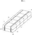
Figure 1 shows a preferred embodiment of the pack described here; -
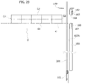
Figures 2A to 2H show successive steps of a preferred embodiment of the method described here; -
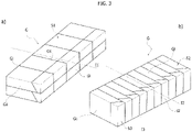
Figure 3 shows two examples of ordered groups of packets. - The following description illustrates various specific details intended to provide a deeper understanding of the embodiments. The embodiments may be realized without one or more of the specific details, or with other methods, components or materials, etc. In other cases, known structures, materials or operations are not shown or described in detail, to avoid obscuring various aspects of the embodiment.
- The references used here are purely for convenience and therefore do not define the scope of protection or the extent of the embodiments.
- As mentioned above, the pack described here is a pack for smoking products, and, in particular, belongs to the type of packs comprising an ordered group of packets containing smoking products and positioned in contact with each other.
- It should be noted that reference will be made in the present text to the specific example of "cigarettes" rather than to the more generic expression "smoking products", without any loss of generality in relation to other types of products (such as cigars, mini cigars or cigarillos, electronic cigarettes or e-cigs, auxiliary products such as filters, refills for e-cigs and other products based on tobacco or on components that are alternatives to, or replacements of, tobacco).
- The pack described here has been devised specifically for making multiple packs of cigarette packets, and reference is made below to this specific application. In all cases, the teachings provided here may also be used for making other types of packs.
- With reference now to
Figure 3 , this shows two examples of groups of packets G that are commonly provided in multiple packs of cigarette packets - In each example, the combination of the packets P forms a parallelepiped. The sides or lateral surfaces Gi of the parallelepiped are defined by the corresponding faces of all the packets that make up the group. On the other hand, the sides Gii are defined by the corresponding faces of a subset of packets of the group G.
- The group of packets G of view a) is formed by pairs of packets side by side and in contact, which are arranged in series and in mutual contact; in the illustrated example, the packets of a single pair are in contact on their respective major faces, although they could alternatively be placed in contact on their respective minor faces.
- The group of packets G of view b), on the other hand, is formed by individual packets arranged in series and in mutual contact; in the illustrated example, the individual packets are in contact on their respective major faces, although they could alternatively be placed in contact on their respective minor faces.
- In relation to the following description, a person skilled in the art will understand that, in general, the solution described here has been devised particularly for groups of packets characterized by packet formations of the 1 x n or 2 x n type, as indicated above for example.
- Returning to
Figure 3 , as a general rule, in the parallelepiped formed by the group of packets G in each example, it is possible to identify a closed lateral surface of tubular shape that delimits two opposite lateral surfaces Gi. In the example of image A) ofFigure 3 , the lateral surface in question, indicated by thereference S 1, is unique and is formed by the four sides Gii of the group of packets G (these sides are denoted below by the references G1, G2, G3, G4 respectively). Thesurface S 1 extends around a reference axis I1 of the group of packets G. On the other hand, in the example of image B) ofFigure 3 , there are two of the closed lateral surfaces of the aforementioned type, namely the surfaces S2 and S3, of which the first is formed by the two sides Gii and the two sides Gi defined by the opposite lateral edges of the individual packets, while the second is formed by the two sides Gii and the two sides Gi defined by the upper and lower faces of the individual packets. The surface S2 extends around areference axis 12 of the group of packets G, and the surface S3 extends around areference axis 13 of the group of packets G, which is orthogonal to thereference axis 12. - Incidentally, it should be noted that the examples provided are purely intended to facilitate the understanding of the solution described here. As a general rule, the type of packets and the configuration of the group G formed from them are not to be interpreted as in any way limiting on the scope of application of the solution. With reference to
Figure 1 , this shows a preferred embodiment of the pack described here, indicated as a whole by the reference numeral 10. - The pack 10 comprises a group G of packets P having a configuration corresponding to that shown in drawing A of
Figure 3 . - According to an important characteristic of the solution described here, the pack 10 comprises an
adhesive tape 2, applied to the closed lateral surface S1 of the group of packets G, which is wrapped completely around the latter, and which, on its own, holds together the packets P of the group. - In preferred embodiments, such as that illustrated, the pack 10 further comprises a second
adhesive tape 4, also applied to the closed lateral surface S1 and wrapped completely around it. Even more preferably, theadhesive tape 4 extends parallel to the firstadhesive tape 2. - According to this preferred embodiment, it is only the two
adhesive tapes - Consequently, the pack described here is formed by the packets P and, additionally, the
tape 2 or thetapes - In preferred embodiments, such as that illustrated, the
tape 2 and/or thetape 4 have respectiveopposite end tabs opposite tabs - In preferred embodiments, such as that illustrated, the
tape 2 and/or thetape 4 have a width of less than 10 mm. - Preferably, the
tapes lateral surface S 1 are kept visible. Preferably, thetapes - The solution described here also relates to a method for making a pack of the aforementioned type, and a machine for the implementation of said method.
- As a general rule, the method described here provides for unwinding the
adhesive tape 2 oradhesive tapes adhesive tape 2 or theadhesive tapes -
Figures 2A to 2H show successive steps of a preferred embodiment of the method described here, implemented by a preferred embodiment of the packaging machine described here. - For simplicity of description, the method will now be illustrated with reference to the application of a single adhesive tape, particularly the
tape 2, but the same teachings may evidently also relate to the application of a second adhesive tape. - With reference to
Figure 2A , the method described here provides, in the first place, for causing the group of packets G to advance in a direction of advance K, in an arrangement in which the theoretical axis I1 of the group of packets G is orthogonal to the direction of advance K; the faces G1, G2, G3, G4, parallel to the theoretical axis I1, which form the closedlateral surface S 1, are arranged two by two, parallel to the direction of advance K or orthogonally thereto. - Preferably, the group of packets G is made to advance by means of a pushing member 108 (shown only in
Figure 2A ). - A continuous
adhesive tape 200 is unwound from a reel and fed in a direction of feed Z, orthogonally to the direction of advance K and to the theoretical axis I1 of the group of packets G. - In one or more preferred embodiments, such as that illustrated, the
tape 200 is moved in the direction of feed Z by means of adriving member 101, which grips the end tab 200A of thetape 200 and draws it with itself in the feed direction Z (Figure 2B ). - As a result of the action of the
driving member 101, theadhesive tape 200 is positioned in front of a first face G1 of thelateral surface S 1 of the group of packets G, with reference to the direction of advance K, and is interposed between the group of packets and apassage 104 which is defined by a first and asecond stop element - For reasons which will be made clear by the following text, the
tape 200 extends in the direction of feed Z beyond thepassage 104 for a predetermined length, at least equal to the length of the face G2 of the lateral surface S1, preferably equal to about half of the perimeter of the lateral surface S1. - After the
tape 200 has been fed in the direction of feed Z by thedriving member 101, the twostop elements Figure 2C ). - In one or more preferred embodiments, such as that illustrated (see
Figure 2C ), the portion of thetape 200 that extends in the direction of feed Z is engaged by asuction plate 105 so as to be retained on a plane containing the same direction of feed Z. - In one or more preferred embodiments, such as that illustrated, the
suction plate 105 forms a single element that also defines thepassage 104 and the twostop elements 102, 103 (the latter being identified by two opposite edges delimiting the passage 104). - The
plate 105 can be moved with an alternating motion in the direction of advance K, between a position shown inFigure 2C , in which itstape support surface 105A is coplanar with the direction of feed Z, and a position shown inFigure 2A , in which thesurface 105A is displaced downstream with reference to the direction of advance K. - The position of
Figure 2C is assumed in order to engage thetape 200 after it has been fed in the direction of feed Z, while the position ofFigure 2A is assumed when the drivingmember 101 moves in the direction Z, to avoid conditions of interference between theplate 105 and the drivingmember 101. - Returning to the method described here, after the
stop elements tape 200, the method provides for causing the group of packets G to advance in the direction of advance K, in order to bring it against theadhesive tape 200 positioned in front of it, and then in order to cause the group of packets G and thetape 200 engaged by it to advance through thepassage 104 defined by the twostop elements 102, 103 (Figures 2D and2E ). - The relative movement between the group of packets G and the two
stop elements tape 200 into a U-shape against the opposite faces G2, G3 of the closed lateral surface S1 of the group of packets G. - Preferably, the relative movement between the group of packets G and the two
stop elements Figure 2E ). - At this point, the method provides for cutting the
tape 200 by means of a cuttingmember 109, in a position along the direction of feed Z which is upstream of theplate 105, in order to separate theadhesive tape 2 that is partially wrapped around the group of packets G from the continuous tape 200 (Figure 2F ). Evidently, the position in which thetape 200 is cut must be such as to provide a sufficient length of theadhesive tape 2 to completely close thetape 2 around the group of packets G. - The
adhesive tape 2 separated from thecontinuous tape 200 is now folded in a U-shape around the group of packets G, and, preferably has twoend tabs 2A extending beyond the faces G2, G3 of the group of packets and retained by corresponding portions of theplate 105 that are opposite each other with respect to thepassage 104. - The method described here then provides for folding the two
tabs 2A of thetape 2 against the face G4 of the group of packets so as to close thetape 2 completely around said group of packets (Figures 2G ,2H ). As mentioned above, the length of thetabs 2A is preferably such that they are brought to a condition of mutual superimposition against the face G4 of the group of packets G. - For this purpose, in preferred embodiments, such as that illustrated, the
plate 105 carries twofolding members 107 which are positioned on opposite sides of thepassage 104 and which are movable towards the inside of this passage and in the theoretical plane thereof, to engage the twoopposite tabs 2A of thetape 2 and bring them against the face G4 of the group of packets. - Preferably, the two
members 107 operate in succession so as to put thetabs 2A into the aforementioned condition of mutual superimposition (Figures 2G and2H ). Before the twofolding members 107 are activated, the group of packets G and theplate 105 are positioned in such a way that the sliding plane of the twofolding members 107 is aligned with the face G4 of the group of packets G (Figure 2F ). Thus the movement of each foldingmember 107 creates an action that presses thetabs 2A against the face G4 of the group of packets. - Preferably, this mutual position between the group of packets G and the
plate 105 is reached as a result of their simultaneous movement in the direction of advance K. In particular, as a result of this movement theplate 105 reaches the position ofFigure 2A ; this is done in such a way that, while the twomembers 107 fold thetabs 2A of the tape, the drivingmember 101 is simultaneously free to move in the direction of feed Z in order to return to its position above theplate 105 to start a new cycle. - As mentioned above, the same method illustrated above may be used for applying the second
adhesive tape 4 to the group of packets G. In particular, a second continuous adhesive tape may be unwound from a further reel and applied to the group of packets G by the same means, and according to the same procedure, as those illustrated above. - The same method illustrated above may also be used for applying at least one adhesive tape around the lateral surface S2 or S3 of the group of packets G illustrated in drawing B of
Figure 3 ; in particular, the group of packets will be orientated with itstheoretical axis 12 orthogonal to the directions K and Z in order to wrap the adhesive tape around the lateral surface S2, or with itstheoretical axis 13 orthogonal to the directions K and Z in order to wrap the adhesive tape around the lateral surface S3. - In view of the above it will be understood that the packaging machine according to the preferred embodiment illustrated above comprises a movement unit provided with the pushing
member 108, and a tape application unit comprising the drivingmember 101, thesuction plate 105 with thepassage 104 and the twofolding members 107, and the cuttingmember 109. - Clearly, provided that the principle of the invention is retained, the details of construction and forms of embodiment can be varied, even to a significant degree, from what has been illustrated herein purely by way of non-limiting example, without thereby departing from the scope of the invention, as defined in the attached claims. For example, in an alternative embodiment, the folding members of the projecting tabs of the tape may be entirely independent of the
plate 105 and may be drivable with a motion which is rotary rather than translational. In other embodiments, theplate 105 may be removed and its function may be performed by the drivingmember 101 in an operating condition in which it retains the tab 200A of the tape and supports the movement of the latter during the folding of the tape around the group of packets G.
Claims (10)
- Method for making a pack (10) of smoking products comprising an ordered group (G) of packets containing smoking products and positioned in contact with each other,wherein said group of packets (G) has a closed lateral surface (S1) around a theoretical axis (II) of the group of packets, which delimits two opposite surfaces (Gi) of the group of packets, each of which surfaces is defined by the set of homologous surfaces of all the packets;the method being characterized in that it includes unwinding at least one adhesive tape (2, 4) from a reel and applying it to the closed lateral surface (S1) and completely around the latter, to hold the packets of the group together solely by means of the at least one adhesive tape (2, 4), wherein unwinding at least one adhesive tape (2, 4) from a reel and applying it to the closed lateral surface (S1) and completely around the latter includes:- causing the group of packets (G) to advance in a direction of advance (K), in an arrangement in which the theoretical axis (I1) of the group of packets (G) is orthogonal to the direction of advance (K);- feeding the at least one adhesive tape (2) in a direction of feed (Z) orthogonal to the direction of advance (K) and to the theoretical axis (I1) of the group of packets (G), and positioning the adhesive tape (2) in front of a first face (G1) of the closed lateral surface of the group of packets, with reference to the direction of advance (K) of the latter, and in contact with a first and a second stop element (102, 103) spaced apart from each other along the direction of feed (Z) of the tape, to define a passage (104) for the group of packets;- causing the group of packets (G) to advance in the direction of advance (K) against the adhesive tape (2) positioned in front of it, and through the passage (104) defined by the two stop elements (102, 103), in such a way that the adhesive tape (2) is folded into a U-shape against a second and a third face (G2, G3), opposite each other, of the closed lateral surface (S 1) of the group of packets (G), as a result of the relative movement between the group of packets (G) and the first and the second stop elements (102, 103);- folding tabs (2A) of the adhesive tape projecting from the second and third face, respectively, of the group of packets, against a fourth face (G4) of the closed lateral surface (S1) of the group of packets, placing the tabs (2A) in mutual superimposition,wherein:- feeding the adhesive tape (2) in the direction of feed (Z) includes causing the adhesive tape (2) to extend in the direction of feed (Z) between the group of packets (G) and the passage (104) defined by the first and second stop elements (102, 103), and beyond said passage (104) over a given length of adhesive tape, at least equal to the length of the second or third face (G2, G3), of the closed lateral surface (S 1) of the group of packets, and- said method provides for retaining the given length of adhesive tape by means of a suction plate (105).
- Method according to Claim 1, wherein feeding the adhesive tape in the direction of feed includes driving the adhesive tape (2) in the direction of feed (Z) by means of a driving member (101).
- Method according to Claim 1, which includes unwinding from a reel at least one continuous adhesive tape (200) including the at least un adhesive tape (2), and cutting the continuous adhesive tape (200) unwound from the reel, after the adhesive tape (2) has been folded in a U-shape, to separate the adhesive tape (2) from the continuous adhesive tape (200) unwound from the reel.
- Method according to Claim 1, wherein causing the group of packets (G) to advance includes pushing the group of packets in the direction of advance (K) by means of a pushing member (108).
- Method according to Claim 1, wherein folding at least one projecting tab (2A) of the adhesive tape (2) includes causing a folding element (107), which engages the projecting tab (2A) of the adhesive tape (2), to slide along the fourth face (G4) of the closed lateral surface (S1) of the group of packets (G).
- Machine for implementing a packaging method according to any of the preceding claims, comprising:- a unit (108) for moving a group of packets (G) in a direction of advance (K), and a unit for applying at least one adhesive tape (2) unwound from a reel to a closed lateral surface (S1) of the group of packets (G) and completely around the latter, to hold the packets of the group together solely by means of the at least one adhesive tape.wherein the unit for applying the adhesive tape comprises:- a member for driving (101) the adhesive tape (2), unwound from a reel, in a direction of feed (Z) of the adhesive tape (2) which is orthogonal to the direction of advance (K) of the group of packets (G); and- a first and a second stop element (102, 103) which are arranged so as to be brought into contact with the adhesive tape (2) in the direction of feed (Z), and are spaced apart from each other along the same direction, to define a passage (104) for the group of packets (G) moving in the direction of advance (K),wherein the unit for moving the group of packets comprises at least one pushing member which is movable in the direction of advance (K), for pushing the group of packets (G) from a first position, in which it is upstream of the passage (104) defined by the first and second stop element (102, 103), to a second position, in which it has at least partially passed through the passage (104) defined by the first and second stop element (102, 103), the relative movement between the group of packets (G) and the first and second stop element (102, 103) causing the adhesive tape to be folded into a U-shape around the closed lateral surface (S 1) of the group of packets (G), andwherein the driving member (101) for the adhesive tape is movable in the direction of feed (Z) to cause the adhesive tape (2) to extend in the direction of feed (Z) between the group of packets (G) in the first position and the passage (104) defined by the first and second stop elements (102, 103), and beyond said passage (104) over a given length of adhesive tape, at least equal to the length of one face (G2, G3) of the closed lateral surface (S1) of the group of packets (G), parallel to the direction of advance (K) of the group of packets (G),said machine including a suction plate (105) for retaining at least the given length of adhesive tape.
- Machine according to Claim 6, wherein the application unit comprises a cutting member (109) for separating the adhesive tape (2) from a continuous adhesive tape (200) unwound from a reel, after the adhesive tape (2) has been folded in a U-shape around the closed lateral surface (S1) of the group of packets (G).
- Machine according to Claim 6, wherein the application unit comprises at least one folding member (107) for folding at least one projecting tab (2A) of the adhesive tape folded in a U-shape around the closed lateral surface (S1) of the group of packets (G), in order to close the adhesive tape (2) completely around the closed lateral surface (S1).
- Pack (10) of smoking products produced by a method according to any of Claims 1 to 6, comprising an ordered group (G) of packets containing smoking products and positioned in contact with each other,wherein said group of packets (G) has a closed lateral surface (S1) around a theoretical axis (I1) of the group of packets (G), which delimits two opposite surfaces (Gi) of the group of packets, each of which surfaces is defined by the set of homologous surfaces or sides of all the packets;the pack being characterized in that it includes:
at least one adhesive tape (2, 4), which is applied to the closed lateral surface (S1) of the group of packets (G) and wrapped completely around the latter, and which, on its own, holds together the packets of the group. - Pack according to Claim 9, comprising a second adhesive tape (4), which is applied to the closed lateral surface (S1) of the group of packets (G) and wrapped completely around the latter, and which extends parallel to the first adhesive tape (2) applied to the closed lateral surface of the group of packets.
Applications Claiming Priority (1)
| Application Number | Priority Date | Filing Date | Title |
|---|---|---|---|
| IT102021000016982A IT202100016982A1 (en) | 2021-06-29 | 2021-06-29 | Packaging for smoking articles |
Publications (1)
| Publication Number | Publication Date |
|---|---|
| EP4112485A1 true EP4112485A1 (en) | 2023-01-04 |
Family
ID=77802104
Family Applications (1)
| Application Number | Title | Priority Date | Filing Date |
|---|---|---|---|
| EP22180483.4A Pending EP4112485A1 (en) | 2021-06-29 | 2022-06-22 | Pack for smoking products |
Country Status (3)
| Country | Link |
|---|---|
| US (1) | US20220411113A1 (en) |
| EP (1) | EP4112485A1 (en) |
| IT (1) | IT202100016982A1 (en) |
Families Citing this family (1)
| Publication number | Priority date | Publication date | Assignee | Title |
|---|---|---|---|---|
| LU101715B1 (en) * | 2020-03-30 | 2021-09-30 | Fuji Seal Int Inc | Method of making a sleeve for covering receptacle, apparatus for making sleeve |
Citations (9)
| Publication number | Priority date | Publication date | Assignee | Title |
|---|---|---|---|---|
| US2605897A (en) * | 1949-10-21 | 1952-08-05 | John B Rundle | Package |
| DE6923785U (en) * | 1969-06-13 | 1969-10-23 | Extrakt Kaffee Gmbh Deutsche | BULK PACKAGING WITH TAPE |
| WO1995006603A1 (en) * | 1993-09-01 | 1995-03-09 | Mccain Foods Limited | Multiple article pack and packaging method |
| DE29518315U1 (en) | 1995-11-18 | 1996-02-08 | Ostma Maschinenbau Gmbh | Outer packaging for a packaging unit consisting of several cigarette boxes |
| EP2305563A2 (en) * | 2009-09-10 | 2011-04-06 | Krones AG | Method and device for producing containers |
| US8046978B2 (en) * | 2009-10-02 | 2011-11-01 | R.J. Reynolds Tobacco Company | Equipment and method for packaging multiple packets of cigarettes |
| WO2014053515A1 (en) | 2012-10-01 | 2014-04-10 | Philip Morris Products S.A. | Package with heat shrink wrapper |
| WO2021094738A1 (en) * | 2019-11-11 | 2021-05-20 | British American Tobacco (Investments) Limited | A collation of packages for delivery systems |
| WO2021239625A1 (en) * | 2020-05-26 | 2021-12-02 | Focke & Co. (Gmbh & Co. Kg) | Method and device for strapping a group of packages |
Family Cites Families (1)
| Publication number | Priority date | Publication date | Assignee | Title |
|---|---|---|---|---|
| DE602006010034D1 (en) * | 2006-05-26 | 2009-12-10 | Mtc Macchine Trasformazione | Paper feeding device for a strapping machine for producing paper rolls |
-
2021
- 2021-06-29 IT IT102021000016982A patent/IT202100016982A1/en unknown
-
2022
- 2022-06-22 EP EP22180483.4A patent/EP4112485A1/en active Pending
- 2022-06-28 US US17/851,104 patent/US20220411113A1/en active Pending
Patent Citations (9)
| Publication number | Priority date | Publication date | Assignee | Title |
|---|---|---|---|---|
| US2605897A (en) * | 1949-10-21 | 1952-08-05 | John B Rundle | Package |
| DE6923785U (en) * | 1969-06-13 | 1969-10-23 | Extrakt Kaffee Gmbh Deutsche | BULK PACKAGING WITH TAPE |
| WO1995006603A1 (en) * | 1993-09-01 | 1995-03-09 | Mccain Foods Limited | Multiple article pack and packaging method |
| DE29518315U1 (en) | 1995-11-18 | 1996-02-08 | Ostma Maschinenbau Gmbh | Outer packaging for a packaging unit consisting of several cigarette boxes |
| EP2305563A2 (en) * | 2009-09-10 | 2011-04-06 | Krones AG | Method and device for producing containers |
| US8046978B2 (en) * | 2009-10-02 | 2011-11-01 | R.J. Reynolds Tobacco Company | Equipment and method for packaging multiple packets of cigarettes |
| WO2014053515A1 (en) | 2012-10-01 | 2014-04-10 | Philip Morris Products S.A. | Package with heat shrink wrapper |
| WO2021094738A1 (en) * | 2019-11-11 | 2021-05-20 | British American Tobacco (Investments) Limited | A collation of packages for delivery systems |
| WO2021239625A1 (en) * | 2020-05-26 | 2021-12-02 | Focke & Co. (Gmbh & Co. Kg) | Method and device for strapping a group of packages |
Also Published As
| Publication number | Publication date |
|---|---|
| IT202100016982A1 (en) | 2022-12-29 |
| US20220411113A1 (en) | 2022-12-29 |
Similar Documents
| Publication | Publication Date | Title |
|---|---|---|
| EP2477907B1 (en) | Packages, in particular for cigarettes, and method and device for producing the same | |
| EP2509889B1 (en) | Method and apparatus for producing packs, in particular for cigarettes | |
| EP2874887B1 (en) | Packing method and machine for producing a sealed package containing a group of tobacco articles | |
| RU2636911C2 (en) | Packaging with tear bands | |
| EP4112485A1 (en) | Pack for smoking products | |
| EP2544958A1 (en) | Pack for cigarettes, and method and apparatus for producing the same | |
| EP2087991A1 (en) | Device and method for manufacturing tobacco bags | |
| ITBO980255A1 (en) | METHOD FOR THE CREATION OF CIGARETTE PACKAGES AND PLANT FOR THE IMPLEMENTATION OF THIS METHOD. | |
| ITTO20090296A1 (en) | DEVICE FOR PACKAGING A PRODUCT IN A BOX | |
| GB2259687A (en) | Cigarette pack with internal spacer; assembly thereof | |
| WO2015128812A1 (en) | Packing method and unit for folding a sheet of packing material around a parallelepipedal product | |
| JP5497305B2 (en) | Method of folding paper for wrapping a group of cigarettes and wrapping unit | |
| JP2010159086A (en) | Packaging method and unit for folding sheet of packing material about parallelopiped-shaped article | |
| JP3790031B2 (en) | Package, in particular a group of cigarette packets and a method of manufacturing the same | |
| WO2014091381A1 (en) | Method for packaging absorbent sanitary articles. | |
| US4258525A (en) | Method and apparatus for wrapping groups of cigarettes | |
| EP1574435A2 (en) | Apparatus and method for packaging tobacco industry products | |
| EP0374712A1 (en) | Wrapping apparatus, particularly for cigarette packs or the like | |
| WO2013145208A1 (en) | Body folding device and body folding method for outer packing material | |
| EP3653518B1 (en) | Feeding method and unit to feed two wrapping sheets in a packing machine | |
| DE60122982T2 (en) | Apparatus for transferring substantially parallelepipedic envelopes | |
| WO2022208225A1 (en) | A method and a machine for producing a package of smoking articles | |
| WO2018173222A1 (en) | Packaging method for manufacturing packaged product, device for forming projected folding line on packaging material, and package accommodating packaged product | |
| US20220048698A1 (en) | Pack of smoking articles | |
| KR20200024542A (en) | Apparatus for packaging paper cups |
Legal Events
| Date | Code | Title | Description |
|---|---|---|---|
| PUAI | Public reference made under article 153(3) epc to a published international application that has entered the european phase |
Free format text: ORIGINAL CODE: 0009012 |
|
| STAA | Information on the status of an ep patent application or granted ep patent |
Free format text: STATUS: THE APPLICATION HAS BEEN PUBLISHED |
|
| AK | Designated contracting states |
Kind code of ref document: A1 Designated state(s): AL AT BE BG CH CY CZ DE DK EE ES FI FR GB GR HR HU IE IS IT LI LT LU LV MC MK MT NL NO PL PT RO RS SE SI SK SM TR |
|
| STAA | Information on the status of an ep patent application or granted ep patent |
Free format text: STATUS: REQUEST FOR EXAMINATION WAS MADE |
|
| 17P | Request for examination filed |
Effective date: 20230328 |
|
| RBV | Designated contracting states (corrected) |
Designated state(s): AL AT BE BG CH CY CZ DE DK EE ES FI FR GB GR HR HU IE IS IT LI LT LU LV MC MK MT NL NO PL PT RO RS SE SI SK SM TR |
|
| P01 | Opt-out of the competence of the unified patent court (upc) registered |
Effective date: 20230524 |