EP4112479A1 - Spark containment cap - Google Patents
Spark containment cap Download PDFInfo
- Publication number
- EP4112479A1 EP4112479A1 EP22180158.2A EP22180158A EP4112479A1 EP 4112479 A1 EP4112479 A1 EP 4112479A1 EP 22180158 A EP22180158 A EP 22180158A EP 4112479 A1 EP4112479 A1 EP 4112479A1
- Authority
- EP
- European Patent Office
- Prior art keywords
- base
- containment cap
- fastener
- spark containment
- cap
- Prior art date
- Legal status (The legal status is an assumption and is not a legal conclusion. Google has not performed a legal analysis and makes no representation as to the accuracy of the status listed.)
- Granted
Links
Images


Classifications
-
- B—PERFORMING OPERATIONS; TRANSPORTING
- B64—AIRCRAFT; AVIATION; COSMONAUTICS
- B64D—EQUIPMENT FOR FITTING IN OR TO AIRCRAFT; FLIGHT SUITS; PARACHUTES; ARRANGEMENT OR MOUNTING OF POWER PLANTS OR PROPULSION TRANSMISSIONS IN AIRCRAFT
- B64D37/00—Arrangements in connection with fuel supply for power plant
- B64D37/32—Safety measures not otherwise provided for, e.g. preventing explosive conditions
-
- F—MECHANICAL ENGINEERING; LIGHTING; HEATING; WEAPONS; BLASTING
- F16—ENGINEERING ELEMENTS AND UNITS; GENERAL MEASURES FOR PRODUCING AND MAINTAINING EFFECTIVE FUNCTIONING OF MACHINES OR INSTALLATIONS; THERMAL INSULATION IN GENERAL
- F16B—DEVICES FOR FASTENING OR SECURING CONSTRUCTIONAL ELEMENTS OR MACHINE PARTS TOGETHER, e.g. NAILS, BOLTS, CIRCLIPS, CLAMPS, CLIPS OR WEDGES; JOINTS OR JOINTING
- F16B37/00—Nuts or like thread-engaging members
- F16B37/14—Cap nuts; Nut caps or bolt caps
-
- B—PERFORMING OPERATIONS; TRANSPORTING
- B64—AIRCRAFT; AVIATION; COSMONAUTICS
- B64D—EQUIPMENT FOR FITTING IN OR TO AIRCRAFT; FLIGHT SUITS; PARACHUTES; ARRANGEMENT OR MOUNTING OF POWER PLANTS OR PROPULSION TRANSMISSIONS IN AIRCRAFT
- B64D45/00—Aircraft indicators or protectors not otherwise provided for
- B64D45/02—Lightning protectors; Static dischargers
-
- F—MECHANICAL ENGINEERING; LIGHTING; HEATING; WEAPONS; BLASTING
- F16—ENGINEERING ELEMENTS AND UNITS; GENERAL MEASURES FOR PRODUCING AND MAINTAINING EFFECTIVE FUNCTIONING OF MACHINES OR INSTALLATIONS; THERMAL INSULATION IN GENERAL
- F16B—DEVICES FOR FASTENING OR SECURING CONSTRUCTIONAL ELEMENTS OR MACHINE PARTS TOGETHER, e.g. NAILS, BOLTS, CIRCLIPS, CLAMPS, CLIPS OR WEDGES; JOINTS OR JOINTING
- F16B33/00—Features common to bolt and nut
- F16B33/004—Sealing; Insulation
-
- F—MECHANICAL ENGINEERING; LIGHTING; HEATING; WEAPONS; BLASTING
- F16—ENGINEERING ELEMENTS AND UNITS; GENERAL MEASURES FOR PRODUCING AND MAINTAINING EFFECTIVE FUNCTIONING OF MACHINES OR INSTALLATIONS; THERMAL INSULATION IN GENERAL
- F16B—DEVICES FOR FASTENING OR SECURING CONSTRUCTIONAL ELEMENTS OR MACHINE PARTS TOGETHER, e.g. NAILS, BOLTS, CIRCLIPS, CLAMPS, CLIPS OR WEDGES; JOINTS OR JOINTING
- F16B37/00—Nuts or like thread-engaging members
- F16B37/14—Cap nuts; Nut caps or bolt caps
- F16B37/145—Sleeve nuts, e.g. combined with bolts
Definitions
- the present invention relates to a spark containment cap.
- the present invention also relates to a fastening system, a fastener joint, an aircraft comprising at least one of the spark containment cap, the fastening system, and the fastening joint, and also relates to a method of securing a fastener and a spark containment cap to a structure.
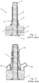
- FIG 1 is a side view of a fastener 1 passing through a panel 2, which may be a composite or metallic panel.
- the type of fastener shown in Figure 1 is commonly known as a blind fastener, as it allows the fastener 1 to be fixed in place from only one side of the panel 2.
- the blind fastener 1 comprises a bolt 3 comprising an axially extending shaft 4, a head of the shaft 5, and a tubular sleeve 6 fitted around the shaft 4.
- the shaft 4 has a threaded portion on its outer circumference at one end which is the opposite end to the head of the shaft 5.
- the tubular sleeve 6 has a corresponding thread on its internal circumference such that the tubular sleeve 6 will travel along the shaft 4 as it is rotated.
- the blind fastener 1 also has a collar 7 provided around a head end 8 of the bolt 3. The collar 7 abuts the head 8, and has a flange 9 at the other end.
- the fastener 1 is slid through an aperture in the panel 2 until the flange 9 has at least passed through the other side of the panel 2.
- the shaft 4 is then rotated to cause the tubular sleeve 6 to be drawn towards the collar 7.
- the tubular sleeve 6 contacts the collar 7, the tubular sleeve 6 deforms along the flange 9, and splays outwardly forming an expanded portion on the opposing side of the panel 2 to the head of the shaft 8, therefore acting as a fastener, as shown in Figure 1 .
- sparking or plasma or out-gassing may occur.
- the panel 2 may provide a fuel tank boundary and the fastener 1 may therefore be immersed in fuel or fuel vapour rich gas.
- a lightning strike at the fastener 1 may therefore provide sparking and hot gas ignition sources which could cause ignition of the fuel.
- FIG 2 shows the fastener 1 of Figure 1 enclosed within an example spark containment cap 20 as known in the prior art.
- the spark containment cap 20 is placed over the tail end of the fastener 1 that protrudes from the panel 2, and can then be fixed into place with adhesive (not shown). The adhesive can be injected into the skirt 21 through the tube 22.
- Blind fasteners allow for fastening from a single side of the panel, which can greatly simplify the assembly process. However, the assembly still requires access to the rear of the panel once the fastener hole has been drilled or the fasteners have been positioned to allow for the positioning of the spark containment caps.
- a spark containment cap for enclosing an end of a fastener protruding from a structure; the enclosed body having a base and a cover portion; the cover portion extending from the base; the base providing an adhering surface for adhering the spark containment cap to a structure; and the base and the cover portion together defining a cavity within the enclosed body inside which the end of a fastener can be enclosed.
- the base may comprise a sacrificial portion into which an opening can be formed, such that the end of a fastener can be received into the cavity through said opening.
- the hole can be formed after the spark containment cap has been fixed in place, and it eliminates any need for highly accurate alignment of the cap and a hole in the structure.
- the enclosed body may be shaped substantially as a hollow conical frustum. This is a space efficient shape which is able to closely encapsulate a blind fastener, and reduces wasted space inside the structure taken up by the spark containment cap.
- the base may comprise a plurality of projections on the adhering surface.
- the plurality of projections serve to maintain a separation distance between the base of the cap and a surface against which it is positioned, and can improve the strength of an adhesive bond between the two.
- the enclosed body may be manufactured as a single piece and may be manufactured using a blow moulding process.
- the spark containment cap can be manufactured very simply, and at very low cost compared to a more traditional spark containment cap which tends to be formed as a complex injection moulded part.
- the enclosed body may comprise one or more alignment features.
- Each of the one or more alignment features may be a rib formed in the cover portion of the enclosed body, or may be a surface marking on the outside surface of the cover portion of the enclosed body. This may aid the accurate positioning of the spark containment cap on the structure, particularly if the cap is positioned prior to a hole being drilled in the structure for the fastener.
- the diameter of the cap may be greater at the base than at the top of the cover.
- the base may comprise an adhesive pad on the adhering surface.
- the adhesive pad may allow the spark containment cap to be held temporarily in place on structure whilst an adhesive is applied and cured, and may prevent accidental movement of the cap prior to the adhesive being cured.
- the adhesive pad may be positioned over less than half of the diameter of the base of the cap. As a result, there is still enough area of the base outside of the adhesive pad to act as an adhering surface to allow for a strong enough adhesive bond between the spark containment cap and the structure.
- An edge formed between the base and the cover portion may be rounded, and the rounded edge may have a first radius.
- the first radius and the second radius may be substantially the same.
- the spark containment cap can be positioned close to features or components on the structure such as ribs and rib feet, which may be beneficial for the optimal positioning of the fastener, allowing for smaller, lighter fasteners, and/or fewer fasteners, which can help to save cost and weight of the assembled product.
- a fastening system comprising a spark containment cap as described in the preceding statements, and a fastener, the spark containment cap being configured to receive part of the fastener.
- the fastener may be a blind fastener.
- the fastening system may further comprise an uncured adhesive, the adhesive being curable to fix the body to the structure.
- the uncured adhesive may comprise non-deformable beads.
- the non-deformable beads serve to maintain a separation distance between the base of the cap and a surface against which it is positioned, and can improve the strength of an adhesive bond between the two.
- a fastener joint comprising: a structure; a fastener having a fastener end protruding from a surface of the structure; and a spark containment cap including: an enclosed body for enclosing the fastener end protruding from the surface of the structure; the enclosed body having a base and a cover portion; the cover portion extending from the base; the base providing an adhering surface for adhering the spark containment cap to the structure; and the base and the cover portion together forming a cavity within the enclosed body inside which the end of a fastener is enclosed; the base comprising a drilled hole through which the end of a fastener is received into the cavity; a cured sealing material provided between the base and the surface of the structure which secures the spark containment cap to the structure and seal a volume of gas within the cavity.
- a method of securing a fastener and a spark containment cap to a structure comprising: fixing a spark containment cap as claimed in any one of claims 1 to 14 onto a surface of the structure; forming a hole through both the structure and the base of the spark containment cap; inserting a blind fastener through the hole and tightening the fastener to secure it to the structure.
- the step of fixing the spark containment cap onto the surface of the structure may comprise applying adhesive between the base of the spark containment cap and the structure, and curing the adhesive.
- the step of fixing the spark containment cap onto the surface of the structure may further comprise using an adhesive pad positioned between the base of the cap and the surface of the structure to hold the spark containment cap in place while the adhesive is cured. As a result, this may prevent accidental movement of the cap prior to the adhesive being fully cured.
- the step of forming a hole through both the structure and the base of the spark containment cap may comprise drilling a common hole through the structure and the base of the affixed spark containment cap.
- an aircraft comprising at least one of a spark containment cap, a fastening system, and a fastener joint as set out in the statements above.
- FIG 3 shows a cross sectional side-view of a spark containment cap 30.
- the spark containment cap 30, which may be referred to herein more simply as cap 30, is shown positioned on a structure 31.
- the structure 31 may be, for example, an aircraft skin panel 31a joined to another component, such as another panel 31b.
- the structure 31 in this embodiment is a composite aircraft structural component, but may be a hybrid composite-metallic component.
- the cap 30 comprises an enclosed body 32.
- the body 32 has a base 33 and a cover portion 34 which extends from the base 33.
- the base 33 provides an adhering surface that can be used for adhering the cap 30 to the structure 31, more details of which will be provided below.
- the base 33 and cover portion 34 together define a cavity 35 within the enclosed body 32. It is into this cavity 35 that the end of a fastener can be received, which will be described in more detail below.
- the cap 30 is manufactured as a single piece, and due to its simplistic form can be manufactured by blow moulding. Often, due to their complex shape, spark containment caps such as the prior art example shown in Figure 2 are typically manufactured by injection moulding. However, blow moulding has lower tooling and production costs compared to injection moulding, and offers a far quicker, easier and cheaper manufacturing alternative, and as such the cap 30 may be considerably cheaper than existing spark containment caps.
- the cap 30 is required to be formed of a material which can be blow moulded, but which is also resistant to long term exposure to fuel. Examples of such a material could be Nylon PA6, PA66 and PA12. Another example may be ULTEM TM 2300, although this material would need to be injection moulded, not blow moulded. These materials may require additional treatment or primer paint application to enhance adhesive properties depending on the requirements of the cap 30.
- the blow moulding process requires there to be a small hole in the moulding to enable the injection / inflation of the plastic into the mould.
- This hole will preferably be provided in the base 33 of the cap 30. The reason for this will become more apparent later, but to summarise briefly this is because a portion of the base 33 is intended to be sacrificial, and a hole will be drilled through it anyway. As such, the blow moulding process hole would be smaller in diameter than the subsequently drilled hole and would not have any impact on the installation or effectiveness of the spark containment cap 30.
- the diameter of the cap 30 at the base 33, as indicated by double arrow A is larger than the diameter of the cap 30 at the top of the cover 34 as indicated by double arrow B.
- the body 32 of the cap 30 therefore substantially takes the shape of a hollow conical frustum. This frusto-conical shape allows for the insertion of the tail end of a blind fastener into the cavity 35, and also allows additional space in the cavity 35 near the base 33 for deformation of a blind fastener sleeve.
- the shape of the body 32 therefore is efficient with respect to the space that it takes up.
- spark containment caps 3 are often installed inside an aircraft wing, and within a fuel tank, it is important that space is not taken up unnecessarily which would reduce the effective fuel tank volume and clash with other components within the wing such as pipes.
- the spark containment cap could be generally cylindrical or domed in shape.
- the cap 30 has an enclosed body 32, it is not necessary for the cap to be accurately aligned with an existing hole in the structure 31 that is intended for a fastener. Instead, the enclosed cap 30 can be fitted and fixed to the structure 31 at a position that coincides with an intended fastening point. Steps in this method will be described with reference to Figures 4 to 6 .
- the cap 30 is slightly oversized compared to the size actually required for it to properly enclose the tail end of a fastener. This slight oversizing compensates for any error in positional accuracy of a subsequent drilling step, axial misalignment of a fastener, and/or an error in the positioning of the cap 30 itself. For example, manufacturing and assembly techniques typically give rise to errors of up to +/- 1mm in drilling and cap placement, and axial misalignment of a fastener tolerance is around +/- 5 degrees.
- the cap 30 is then fixed to the structure using either an epoxy adhesive, shim material or polysulphide sealant.
- the epoxy adhesive may be a two-part epoxy adhesive such as 3M TM Scotch-Weld TM Structural Epoxy Adhesive 9323 or 3M TM Scotch-Weld TM Structural Epoxy Adhesive EC-7256 B/A.
- an adhesive may be used that contains non-deformable beads.
- the non-deformable beads act to maintain a separation distance between the base 33 of the cap 30 and the surface of the structure 31. This ensures a minimum bond thickness equal to the diameter of the beads, thus strengthening the bond between the cap 30 and the structure 31.
- An example of such an adhesive is 3M TM Scotch-Weld TM EC-7202 B/A Epoxy Adhesive ⁇ IPS 10-04-011-04 which contains glass beads that ensure a minimum bond line thickness of 150 ⁇ m.
- the base 33 provides an adhering surface that can be used for adhering the cap 30 to the structure 31.
- Adhesive is applied to the base 33 and the cap is positioned on the surface of the structure 31 and allowed to cure.
- Excess adhesive may form a bead 37 around the periphery of the cap as shown in Figure 4 .
- This bead 37 helps to strengthen the bond between the cap 30 and the structure 31, and also later acts to seal the cavity 35 inside the body 32 once a fastener is fitted in place in order to prevent escape of outgassing products.
- the seal between the cap 30 and the structure 31 also prevents the ingress of fuel, water or other contaminants into the cavity 35, and also prevents plasma or other out-gassing products from exiting the cavity in the event of a lightning strike.
- a hole 40 is drilled through the structure 31 through which a fastener can be inserted.
- a drill bit 41 is used to drill through the structure 31 at the intended fastening point position, extending through the structure and then back out again, as represented by the arrow C.
- the drill bit 41 is shaped such that a countersunk hole 40 is produced to correspond with the shape of the blind fastener to be used.
- the drill bit also creates a hole 42 through a sacrificial portion of the base 33 of the cap 30. As such, a common hole is created through the structure and the base of the affixed spark containment cap.
- a blind fastener 50 is inserted through the hole 40.
- the blind fastener 50 is of the same type described in relation to Figure 1 , and comprises a bolt 53 comprising an axially extending shaft 54, a head of the shaft 55, and a tubular sleeve 56 fitted around the shaft 54.
- the shaft 54 has a threaded portion on its outer circumference at one end which is the opposite end to the head of the shaft 55.
- the tubular sleeve 56 has a corresponding thread on its internal circumference such that the tubular sleeve 56 will travel along the shaft 54 as it is rotated.
- the blind fastener 53 also has a collar 57 provided around a head end of the bolt 53. The collar 57 abuts the head, and has a flange 59 at the other end.
- the blind fastener 50 is slid through the drilled hole in the structure 31 until the flange 59 has at least passed through the other side of the structure 31 and the base 33 of the spark containment cap 30.
- the shaft 54 is then rotated as shown by arrow D to cause the tubular sleeve 6 to be drawn towards the collar 7, indicated by arrows E.
- the tubular sleeve 56 contacts the collar 57, the tubular sleeve 56 deforms along the flange 59, and splays outwardly forming an expanded portion (sometimes referred to as a bulb) on the inside of the base 33 of the cap 30.
- the fastening system comprises the spark containment cap 30 together with the blind fastener 50.
- the adhesive 37 that is used to fix the spark containment cap 30 to the structure also forms part of the fastening system.
- FIG. 6 shows a fastener joint 60 that is the end result once the blind fastener 50 has been fastened to the structure 31 as described above.
- the spark containment cap 30 is fixed to the structure 31 by a cured sealing material in the form of adhesive 37 provided between the base 30 and the surface of the structure 31.
- the blind fastener 50 protrudes through the hole 40 formed in the structure 31 and the base 33 of the cap 30, such that the end of the fastener is enclosed within the cavity 35 in the enclosed body 32 defined by the base 33 and the cover portion 34.
- Figure 7 shows an alternative embodiment of a spark containment cap 70.
- the cap 70 comprises an enclosed body 72.
- the body 72 has a base 73 and a cover portion 74 which extends from the base 73.
- the base 73 provides an adhering surface that can be used for adhering the cap 70 to a structure, and comprises a sacrificial portion that can be drilled to create a hole in the base 73.
- the base 73 and cover portion 74 together define a cavity 75 within the enclosed body 72.
- the cap 70 also comprises a number of projections 76 provided on the outside surface of the base 73.
- the projections 76 act to maintain a defined separation distance between the base 73 of the cap 70 and a surface of a structure to which the cap is to be affixed. This provides an alternative to requiring the adhesive that contains non-deformable beads described above. Instead, the projections 76 ensure a minimum bond thickness equal to the height of the projections, thus ensuring a strong bond between the cap 70 and a structure.
- Figure 7 also shows an adhesive pad 78 which can be fixed (signified by arrow F) to the adhering surface on the base 73 of the cap 70.
- the adhesive pad 78 is able to temporarily hold the cap 70 to a structure whilst the adhesive or other sealing material is curing. This reduces any risk of the cap moving or becoming dislodged before curing is complete.
- the size of the adhesive pad 78 allows for a satisfactory temporary hold, but without significantly affecting the effectiveness of the adhesive/sealant bond. For instance, the adhesive pad would be less than half of the diameter of the base 73 of the cap 70.
- an adhesive pad 78 may not be required if the thixotropic properties of the sealant or adhesive are sufficient to hold the cap 70 in position during curing.
- alignment features in the form of ribs 79 formed in the cover portion 74 of the enclosed body 72 are also shown in the embodiment of Figure 7.
- the ribs 79 allow for sufficiently accurate positioning of the cap when positioning it onto a structure to which it is to be fixed.
- Some assembly methods may use robots to position and fix the cap 70 in place, and in these methods, the robot would likely have built-in positioning systems to ensure accurate placement of the cap 70 onto a structure.
- alignment features such as the ribs 79 can aid the person carrying out the task.
- Figure 8 shows a top view of a spark containment cap 80 positioned on a structure 81.
- the structure 81 is provided with markings shown as dotted lines 82a and 82b.
- the markings 82a and 82b form a target, indicating where an intended fastening point is to be where the lines 82a and 82b cross. The point at which they cross is obscured by the cap 80, but the lines extend far enough to be visible outside the outer diameter of the cap 80.
- the cap 80 is provided with alignment features in the form of surface markings 83a, 83b, 83c, 83d.
- the surface markings 83a, 83b, 83c, 83d can be aligned with the markings 82a and 82b on the structure 81 in order to position the spark containment cap 80 correctly.
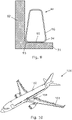
- FIG. 9 shows how a spark containment cap 90 can be positioned on a structure 91 next to a rib fillet 92.
- the edge 93 formed between the fillet 92 and the structure 91 has a natural radius.
- the cap 90 is manufactured such that the edge 94 formed between the base 95 and the cover portion 96 has a radius the substantially matches the radius of the edge on the structure.
- the cap may be manufactured such that the edge 94 has a radius of around 5mm, and this will enable fitment into close proximity of a fillet on a structure having an edge of similar radius of around 5mm.
- the spark containment caps, fastening systems, fastener joints and corresponding methods of assembly may be used in any application, but most preferably the are used in an aircraft such as the aircraft 100 shown in Figure 10 .
- the aircraft 100 includes a fuselage 102.
- Two wings 103 extend from the fuselage 102. It will be appreciated that the fuselage 102 and wings 103 may take a variety of different planned formed shapes and profiles depending on the particular application.
- Fuel tanks 104 are formed in the fuselage 102 and wings 103.
- One such fuel tank 104 is schematically shown in Figure 10 .
- the upper and lower boundaries of the tank 104 are provided by upper and lower skins of the wing 103, and the fore and aft boundaries are provided by forward and rear spars of the wing.
- the spark containment cap and the tail of the blind fastener may be located within the interior of the fuel tank 104.
- the adhesives described above which can be used to fix a spark containment cap to a structure are all two-part epoxy adhesives.
- an adhesive could be used which is cured using UV light.
- a further alternative could provide the spark containment cap with an integrated annular skirt to provide an annular sealing volume extending around the base of the cap.
- This annular skirt could be arranged to receive an annular bead of the adhesive or other curable sealing material. This may be desirable if a more controlled adhesive application around the base of the cap is required.
- the skirt could be provided with an inlet, similar to the one shown on the cap of Figure 2 , through which the adhesive is injected into the skirt.
Landscapes
- Engineering & Computer Science (AREA)
- General Engineering & Computer Science (AREA)
- Mechanical Engineering (AREA)
- Aviation & Aerospace Engineering (AREA)
- Standing Axle, Rod, Or Tube Structures Coupled By Welding, Adhesion, Or Deposition (AREA)
- Connection Of Plates (AREA)
Abstract
Description
- The present invention relates to a spark containment cap. The present invention also relates to a fastening system, a fastener joint, an aircraft comprising at least one of the spark containment cap, the fastening system, and the fastening joint, and also relates to a method of securing a fastener and a spark containment cap to a structure.
- Large passenger aircraft are typically struck by lightning once or twice a year, each lightning bolt striking with up to 200,000 amps of electrical current that seeks the path of least electrical resistance. Many modern passenger aircraft have exterior surfaces made from composite materials which have a very high electrical resistance. There is therefore a high probability of lightning attachment at any of the many metallic fasteners in the exterior surface, which have a much lower electrical resistance. In the wing, some of these fasteners pass through the outer wing skin into the fuel tank.
-
Figure 1 is a side view of afastener 1 passing through apanel 2, which may be a composite or metallic panel. The type of fastener shown inFigure 1 is commonly known as a blind fastener, as it allows thefastener 1 to be fixed in place from only one side of thepanel 2. Theblind fastener 1 comprises abolt 3 comprising an axially extendingshaft 4, a head of the shaft 5, and atubular sleeve 6 fitted around theshaft 4. Theshaft 4 has a threaded portion on its outer circumference at one end which is the opposite end to the head of the shaft 5. Thetubular sleeve 6 has a corresponding thread on its internal circumference such that thetubular sleeve 6 will travel along theshaft 4 as it is rotated. Theblind fastener 1 also has acollar 7 provided around ahead end 8 of thebolt 3. Thecollar 7 abuts thehead 8, and has aflange 9 at the other end. - During installation, the
fastener 1 is slid through an aperture in thepanel 2 until theflange 9 has at least passed through the other side of thepanel 2. Theshaft 4 is then rotated to cause thetubular sleeve 6 to be drawn towards thecollar 7. When thetubular sleeve 6 contacts thecollar 7, thetubular sleeve 6 deforms along theflange 9, and splays outwardly forming an expanded portion on the opposing side of thepanel 2 to the head of theshaft 8, therefore acting as a fastener, as shown inFigure 1 . - In the event of a lightning strike hitting the
panel 2 and attaching to thefastener 1, sparking or plasma or out-gassing may occur. - With the above arrangements, the
panel 2 may provide a fuel tank boundary and thefastener 1 may therefore be immersed in fuel or fuel vapour rich gas. A lightning strike at thefastener 1 may therefore provide sparking and hot gas ignition sources which could cause ignition of the fuel. - It is well known to suppress such sparking by enclosing fasteners within spark containment caps.
Figure 2 shows thefastener 1 ofFigure 1 enclosed within an examplespark containment cap 20 as known in the prior art. Thespark containment cap 20 is placed over the tail end of thefastener 1 that protrudes from thepanel 2, and can then be fixed into place with adhesive (not shown). The adhesive can be injected into theskirt 21 through thetube 22. - Blind fasteners allow for fastening from a single side of the panel, which can greatly simplify the assembly process. However, the assembly still requires access to the rear of the panel once the fastener hole has been drilled or the fasteners have been positioned to allow for the positioning of the spark containment caps.
- According to a first aspect of the invention, there is provided a spark containment cap for enclosing an end of a fastener protruding from a structure; the enclosed body having a base and a cover portion; the cover portion extending from the base; the base providing an adhering surface for adhering the spark containment cap to a structure; and the base and the cover portion together defining a cavity within the enclosed body inside which the end of a fastener can be enclosed.
- With such an arrangement it is possible to fix the spark containment cap in place on a structure prior to a fastener being fastened to the structure, and even before the hole for the fastener is made. As such, it is not necessary for there to be access required to a rear side of the structure after the hole is drilled and the fastener is put in place. This can enable a much quicker, simpler and more efficient assembly process.
- The base may comprise a sacrificial portion into which an opening can be formed, such that the end of a fastener can be received into the cavity through said opening. As such, the hole can be formed after the spark containment cap has been fixed in place, and it eliminates any need for highly accurate alignment of the cap and a hole in the structure.
- The enclosed body may be shaped substantially as a hollow conical frustum. This is a space efficient shape which is able to closely encapsulate a blind fastener, and reduces wasted space inside the structure taken up by the spark containment cap.
- The base may comprise a plurality of projections on the adhering surface. As a result, the plurality of projections serve to maintain a separation distance between the base of the cap and a surface against which it is positioned, and can improve the strength of an adhesive bond between the two.
- The enclosed body may be manufactured as a single piece and may be manufactured using a blow moulding process. As such, the spark containment cap can be manufactured very simply, and at very low cost compared to a more traditional spark containment cap which tends to be formed as a complex injection moulded part.
- The enclosed body may comprise one or more alignment features. Each of the one or more alignment features may be a rib formed in the cover portion of the enclosed body, or may be a surface marking on the outside surface of the cover portion of the enclosed body. This may aid the accurate positioning of the spark containment cap on the structure, particularly if the cap is positioned prior to a hole being drilled in the structure for the fastener.
- The diameter of the cap may be greater at the base than at the top of the cover.
- The base may comprise an adhesive pad on the adhering surface. The adhesive pad may allow the spark containment cap to be held temporarily in place on structure whilst an adhesive is applied and cured, and may prevent accidental movement of the cap prior to the adhesive being cured.
- The adhesive pad may be positioned over less than half of the diameter of the base of the cap. As a result, there is still enough area of the base outside of the adhesive pad to act as an adhering surface to allow for a strong enough adhesive bond between the spark containment cap and the structure.
- An edge formed between the base and the cover portion may be rounded, and the rounded edge may have a first radius.
- When the spark containment cap is positioned on a structure with an edge having a second radius, the first radius and the second radius may be substantially the same. As a result, the spark containment cap can be positioned close to features or components on the structure such as ribs and rib feet, which may be beneficial for the optimal positioning of the fastener, allowing for smaller, lighter fasteners, and/or fewer fasteners, which can help to save cost and weight of the assembled product.
- According to a second aspect of the invention, there is provided a fastening system comprising a spark containment cap as described in the preceding statements, and a fastener, the spark containment cap being configured to receive part of the fastener.
- The fastener may be a blind fastener.
- The fastening system may further comprise an uncured adhesive, the adhesive being curable to fix the body to the structure.
- The uncured adhesive may comprise non-deformable beads. As a result, the non-deformable beads serve to maintain a separation distance between the base of the cap and a surface against which it is positioned, and can improve the strength of an adhesive bond between the two.
- According to a third aspect of the invention, there is provided a fastener joint comprising: a structure; a fastener having a fastener end protruding from a surface of the structure; and a spark containment cap including: an enclosed body for enclosing the fastener end protruding from the surface of the structure; the enclosed body having a base and a cover portion; the cover portion extending from the base; the base providing an adhering surface for adhering the spark containment cap to the structure; and the base and the cover portion together forming a cavity within the enclosed body inside which the end of a fastener is enclosed; the base comprising a drilled hole through which the end of a fastener is received into the cavity; a cured sealing material provided between the base and the surface of the structure which secures the spark containment cap to the structure and seal a volume of gas within the cavity.
- According to a fourth aspect of the invention, there is provided a method of securing a fastener and a spark containment cap to a structure, the method comprising: fixing a spark containment cap as claimed in any one of
claims 1 to 14 onto a surface of the structure; forming a hole through both the structure and the base of the spark containment cap; inserting a blind fastener through the hole and tightening the fastener to secure it to the structure. - With such a method, true one-sided drilling and assembly can be achieved, with the spark containment cap being fitted to the structure prior to the drilling and assembly process. This method also reduces or even eliminates the need for access to the rear side of the structure after drilling has taken place, which can greatly simplify the assembly process, and improve the time taken to assemble.
- The step of fixing the spark containment cap onto the surface of the structure may comprise applying adhesive between the base of the spark containment cap and the structure, and curing the adhesive.
- The step of fixing the spark containment cap onto the surface of the structure may further comprise using an adhesive pad positioned between the base of the cap and the surface of the structure to hold the spark containment cap in place while the adhesive is cured. As a result, this may prevent accidental movement of the cap prior to the adhesive being fully cured.
- The step of forming a hole through both the structure and the base of the spark containment cap may comprise drilling a common hole through the structure and the base of the affixed spark containment cap. With such a method, there is no need for accurate positioning of the cap with an existing hole in the structure, greatly simplifying the assembly process and reducing the time taken.
- According to a fourth aspect of the invention, there is provided an aircraft comprising at least one of a spark containment cap, a fastening system, and a fastener joint as set out in the statements above.
- Embodiments of the invention will now be described with reference to the accompanying drawings, in which:
-
Figure 1 is a cross-sectional side view of a prior art blind fastener joint; -
Figure 2 is a cross-sectional side view of the prior art blind fastener joint with a spark containment cap; -
Figure 3 is a cross-sectional side view of a spark containment cap positioned on a structure; -
Figures 4 ,5, and 6 show steps in a method of securing a fastener and the spark containment cap ofFigure 3 to the structure; -
Figure 7 is a cross-sectional side view of another embodiment of a spark containment cap; -
Figure 8 is a top view of another embodiment of a spark containment cap on a structure; -
Figure 9 is a cross-sectional side view of a spark containment cap positioned on a structure having a rib; -
Figure 10 is a perspective view of an aircraft. -
Figure 3 shows a cross sectional side-view of aspark containment cap 30. Thespark containment cap 30, which may be referred to herein more simply ascap 30, is shown positioned on astructure 31. Thestructure 31 may be, for example, anaircraft skin panel 31a joined to another component, such as anotherpanel 31b. Thestructure 31 in this embodiment is a composite aircraft structural component, but may be a hybrid composite-metallic component. - The
cap 30 comprises anenclosed body 32. Thebody 32 has abase 33 and acover portion 34 which extends from thebase 33. Thebase 33 provides an adhering surface that can be used for adhering thecap 30 to thestructure 31, more details of which will be provided below. Thebase 33 andcover portion 34 together define acavity 35 within theenclosed body 32. It is into thiscavity 35 that the end of a fastener can be received, which will be described in more detail below. - The
cap 30 is manufactured as a single piece, and due to its simplistic form can be manufactured by blow moulding. Often, due to their complex shape, spark containment caps such as the prior art example shown inFigure 2 are typically manufactured by injection moulding. However, blow moulding has lower tooling and production costs compared to injection moulding, and offers a far quicker, easier and cheaper manufacturing alternative, and as such thecap 30 may be considerably cheaper than existing spark containment caps. - The
cap 30 is required to be formed of a material which can be blow moulded, but which is also resistant to long term exposure to fuel. Examples of such a material could be Nylon PA6, PA66 and PA12. Another example may be ULTEM™ 2300, although this material would need to be injection moulded, not blow moulded. These materials may require additional treatment or primer paint application to enhance adhesive properties depending on the requirements of thecap 30. - The blow moulding process requires there to be a small hole in the moulding to enable the injection / inflation of the plastic into the mould. This hole will preferably be provided in the
base 33 of thecap 30. The reason for this will become more apparent later, but to summarise briefly this is because a portion of thebase 33 is intended to be sacrificial, and a hole will be drilled through it anyway. As such, the blow moulding process hole would be smaller in diameter than the subsequently drilled hole and would not have any impact on the installation or effectiveness of thespark containment cap 30. - The diameter of the
cap 30 at thebase 33, as indicated by double arrow A is larger than the diameter of thecap 30 at the top of thecover 34 as indicated by double arrow B. Thebody 32 of thecap 30 therefore substantially takes the shape of a hollow conical frustum. This frusto-conical shape allows for the insertion of the tail end of a blind fastener into thecavity 35, and also allows additional space in thecavity 35 near thebase 33 for deformation of a blind fastener sleeve. The shape of thebody 32 therefore is efficient with respect to the space that it takes up. As these spark containment caps 3 are often installed inside an aircraft wing, and within a fuel tank, it is important that space is not taken up unnecessarily which would reduce the effective fuel tank volume and clash with other components within the wing such as pipes. In an alternative embodiment, however, the spark containment cap could be generally cylindrical or domed in shape. - One of the biggest advantages of the
cap 30 is that, as it has an enclosedbody 32, it is not necessary for the cap to be accurately aligned with an existing hole in thestructure 31 that is intended for a fastener. Instead, theenclosed cap 30 can be fitted and fixed to thestructure 31 at a position that coincides with an intended fastening point. Steps in this method will be described with reference toFigures 4 to 6 . - The
cap 30 is slightly oversized compared to the size actually required for it to properly enclose the tail end of a fastener. This slight oversizing compensates for any error in positional accuracy of a subsequent drilling step, axial misalignment of a fastener, and/or an error in the positioning of thecap 30 itself. For example, manufacturing and assembly techniques typically give rise to errors of up to +/- 1mm in drilling and cap placement, and axial misalignment of a fastener tolerance is around +/- 5 degrees. - Once the
cap 30 has been placed in a desired position on the surface of thestructure 31, as shown inFigure 3 , thecap 30 is then fixed to the structure using either an epoxy adhesive, shim material or polysulphide sealant. For example, the epoxy adhesive may be a two-part epoxy adhesive such as 3M™ Scotch-Weld ™ Structural Epoxy Adhesive 9323 or 3M™ Scotch-Weld ™ Structural Epoxy Adhesive EC-7256 B/A. - In one embodiment, an adhesive may be used that contains non-deformable beads. The non-deformable beads act to maintain a separation distance between the base 33 of the
cap 30 and the surface of thestructure 31. This ensures a minimum bond thickness equal to the diameter of the beads, thus strengthening the bond between thecap 30 and thestructure 31. An example of such an adhesive is 3M™ Scotch-Weld ™ EC-7202 B/A Epoxy Adhesive ∗IPS 10-04-011-04 which contains glass beads that ensure a minimum bond line thickness of 150 µm. - As described earlier, the
base 33 provides an adhering surface that can be used for adhering thecap 30 to thestructure 31. Adhesive is applied to thebase 33 and the cap is positioned on the surface of thestructure 31 and allowed to cure. Excess adhesive may form abead 37 around the periphery of the cap as shown inFigure 4 . Thisbead 37 helps to strengthen the bond between thecap 30 and thestructure 31, and also later acts to seal thecavity 35 inside thebody 32 once a fastener is fitted in place in order to prevent escape of outgassing products. The seal between thecap 30 and thestructure 31 also prevents the ingress of fuel, water or other contaminants into thecavity 35, and also prevents plasma or other out-gassing products from exiting the cavity in the event of a lightning strike. - As shown in
Figure 4 , once thecap 30 is fixed to thestructure 31, ahole 40 is drilled through thestructure 31 through which a fastener can be inserted. Adrill bit 41 is used to drill through thestructure 31 at the intended fastening point position, extending through the structure and then back out again, as represented by the arrow C. Thedrill bit 41 is shaped such that acountersunk hole 40 is produced to correspond with the shape of the blind fastener to be used. As thecap 30 is now fixed to the rear of thestructure 31 at the intended fastening point position, the drill bit also creates ahole 42 through a sacrificial portion of thebase 33 of thecap 30. As such, a common hole is created through the structure and the base of the affixed spark containment cap. - In the next step, shown in
Figure 5 , ablind fastener 50 is inserted through thehole 40. Theblind fastener 50 is of the same type described in relation toFigure 1 , and comprises abolt 53 comprising anaxially extending shaft 54, a head of theshaft 55, and atubular sleeve 56 fitted around theshaft 54. Theshaft 54 has a threaded portion on its outer circumference at one end which is the opposite end to the head of theshaft 55. Thetubular sleeve 56 has a corresponding thread on its internal circumference such that thetubular sleeve 56 will travel along theshaft 54 as it is rotated. Theblind fastener 53 also has acollar 57 provided around a head end of thebolt 53. Thecollar 57 abuts the head, and has aflange 59 at the other end. - During installation, the
blind fastener 50 is slid through the drilled hole in thestructure 31 until theflange 59 has at least passed through the other side of thestructure 31 and thebase 33 of thespark containment cap 30. Theshaft 54 is then rotated as shown by arrow D to cause thetubular sleeve 6 to be drawn towards thecollar 7, indicated by arrows E. When thetubular sleeve 56 contacts thecollar 57, thetubular sleeve 56 deforms along theflange 59, and splays outwardly forming an expanded portion (sometimes referred to as a bulb) on the inside of thebase 33 of thecap 30. - As such it can be said that there is a fastening system provided in
Figure 5 , where the fastening system comprises thespark containment cap 30 together with theblind fastener 50. The adhesive 37 that is used to fix thespark containment cap 30 to the structure also forms part of the fastening system. -
Figure 6 shows a fastener joint 60 that is the end result once theblind fastener 50 has been fastened to thestructure 31 as described above. In the completedfastener joint 60 ofFigure 6 , thespark containment cap 30 is fixed to thestructure 31 by a cured sealing material in the form of adhesive 37 provided between the base 30 and the surface of thestructure 31. Theblind fastener 50 protrudes through thehole 40 formed in thestructure 31 and thebase 33 of thecap 30, such that the end of the fastener is enclosed within thecavity 35 in theenclosed body 32 defined by thebase 33 and thecover portion 34. -
Figure 7 shows an alternative embodiment of aspark containment cap 70. As with the previously described cap above, thecap 70 comprises anenclosed body 72. Thebody 72 has abase 73 and acover portion 74 which extends from thebase 73. Thebase 73 provides an adhering surface that can be used for adhering thecap 70 to a structure, and comprises a sacrificial portion that can be drilled to create a hole in thebase 73. Thebase 73 andcover portion 74 together define acavity 75 within theenclosed body 72. - The
cap 70 also comprises a number ofprojections 76 provided on the outside surface of thebase 73. Theprojections 76 act to maintain a defined separation distance between the base 73 of thecap 70 and a surface of a structure to which the cap is to be affixed. This provides an alternative to requiring the adhesive that contains non-deformable beads described above. Instead, theprojections 76 ensure a minimum bond thickness equal to the height of the projections, thus ensuring a strong bond between thecap 70 and a structure. To provide a stable base, there are preferably at least threeprojections 76 provided in a spaced apart configuration on thebase 73. -
Figure 7 also shows anadhesive pad 78 which can be fixed (signified by arrow F) to the adhering surface on thebase 73 of thecap 70. Theadhesive pad 78 is able to temporarily hold thecap 70 to a structure whilst the adhesive or other sealing material is curing. This reduces any risk of the cap moving or becoming dislodged before curing is complete. The size of theadhesive pad 78 allows for a satisfactory temporary hold, but without significantly affecting the effectiveness of the adhesive/sealant bond. For instance, the adhesive pad would be less than half of the diameter of thebase 73 of thecap 70. Of course, it will be understood that anadhesive pad 78 may not be required if the thixotropic properties of the sealant or adhesive are sufficient to hold thecap 70 in position during curing. - Also shown in the embodiment of
Figure 7 are alignment features in the form ofribs 79 formed in thecover portion 74 of theenclosed body 72. Theribs 79 allow for sufficiently accurate positioning of the cap when positioning it onto a structure to which it is to be fixed. Some assembly methods may use robots to position and fix thecap 70 in place, and in these methods, the robot would likely have built-in positioning systems to ensure accurate placement of thecap 70 onto a structure. However, if thecap 70 is to be fitted manually, then alignment features, such as theribs 79 can aid the person carrying out the task. - Another embodiment is shown in
Figure 8 which shows a top view of aspark containment cap 80 positioned on astructure 81. Thestructure 81 is provided with markings shown as dottedlines markings lines cap 80, but the lines extend far enough to be visible outside the outer diameter of thecap 80. Thecap 80 is provided with alignment features in the form ofsurface markings surface markings markings structure 81 in order to position thespark containment cap 80 correctly. - When used in environments such as on aircraft, it can be beneficial to install spark containment caps in close proximity to structural features such as rib fillets. By locating fasteners close to such structural features, a stronger and more reliable fastening can be achieved. As a result, smaller or fewer bolts may be necessary, which in turn can provide an optimised design that is cheaper and lighter. However, it can be challenging to fit spark containment caps close to said structural features.
Figure 9 shows how aspark containment cap 90 can be positioned on astructure 91 next to arib fillet 92. - The
edge 93 formed between thefillet 92 and thestructure 91 has a natural radius. Thecap 90 is manufactured such that theedge 94 formed between the base 95 and thecover portion 96 has a radius the substantially matches the radius of the edge on the structure. By matching the radius on thecap 90 with the radius on thestructure 91, it is possible to fit thecap 90 as close to thefillet 92 as possible whilst not reducing the amount of adhesive area and bonding strength. For example, the cap may be manufactured such that theedge 94 has a radius of around 5mm, and this will enable fitment into close proximity of a fillet on a structure having an edge of similar radius of around 5mm. - The spark containment caps, fastening systems, fastener joints and corresponding methods of assembly may be used in any application, but most preferably the are used in an aircraft such as the
aircraft 100 shown inFigure 10 . Theaircraft 100 includes afuselage 102. Twowings 103 extend from thefuselage 102. It will be appreciated that thefuselage 102 andwings 103 may take a variety of different planned formed shapes and profiles depending on the particular application.Fuel tanks 104 are formed in thefuselage 102 andwings 103. Onesuch fuel tank 104 is schematically shown inFigure 10 . The upper and lower boundaries of thetank 104 are provided by upper and lower skins of thewing 103, and the fore and aft boundaries are provided by forward and rear spars of the wing. In the embodiments described above, the spark containment cap and the tail of the blind fastener may be located within the interior of thefuel tank 104. - Where the word 'or' appears this is to be construed to mean 'and/or' such that items referred to are not necessarily mutually exclusive and may be used in any appropriate combination.
- Although the invention has been described above with reference to one or more preferred embodiments, it will be appreciated that various changes or modifications may be made without departing from the scope of the invention as defined in the appended claims.
- For example, the adhesives described above which can be used to fix a spark containment cap to a structure are all two-part epoxy adhesives. However, in an alternative embodiment, an adhesive could be used which is cured using UV light. In this embodiment, it may be beneficial to form the spark containment cap from a transparent material which can allow UV curing of the adhesive through the cap.
- A further alternative could provide the spark containment cap with an integrated annular skirt to provide an annular sealing volume extending around the base of the cap. This annular skirt could be arranged to receive an annular bead of the adhesive or other curable sealing material. This may be desirable if a more controlled adhesive application around the base of the cap is required. For example the skirt could be provided with an inlet, similar to the one shown on the cap of
Figure 2 , through which the adhesive is injected into the skirt.
Claims (19)
- A spark containment cap comprising an enclosed body for enclosing an end of a fastener protruding from a structure;the enclosed body having a base and a cover portion; the cover portion extending from the base;the base providing an adhering surface for adhering the spark containment cap to a structure; andthe base and the cover portion together defining a cavity within the enclosed body inside which the end of a fastener can be enclosed.
- A spark containment cap according to claim 1, wherein the base comprises a sacrificial portion into which an opening can be formed, such that the end of a fastener can be received into the cavity through said opening.
- A spark containment cap according to claim 1 or claim 2, wherein the enclosed body is shaped substantially as a hollow conical frustum.
- A spark containment cap according to any one of the preceding claims, wherein the base comprises a plurality of projections on the adhering surface.
- A spark containment cap according to any one of the preceding claims, wherein the enclosed body is manufactured as a single piece.
- A spark containment cap according to any one of the preceding claims, wherein the enclosed body is manufactured using a blow moulding process.
- A spark containment cap according to any one of the preceding claims, wherein the enclosed body comprises one or more alignment features.
- A spark containment cap according to claim 7, wherein each of the one or more alignment features is one of a rib formed in the cover portion of the enclosed body, and a surface marking on the outside surface of the cover portion of the enclosed body.
- A spark containment cap according to any one of the preceding claims, wherein the base comprises an adhesive pad on the adhering surface.
- A spark containment cap according to claim 9, wherein the adhesive pad is positioned over less than half of the diameter of the base of the cap.
- A spark containment cap according to any one of the preceding claims, wherein an edge formed between the base and the cover portion is rounded, and the rounded edge has a first radius.
- A fastening system comprising a spark containment cap as claimed in any preceding claim, and a fastener, the spark containment cap being configured to receive part of the fastener.
- A fastening system as claimed in claim 12, further comprising uncured adhesive, the adhesive being curable to fix the body to the structure, and wherein the uncured adhesive comprises non-deformable beads.
- A fastener joint comprising:a structure;a fastener having a fastener end protruding from a surface of the structure; anda spark containment cap including:an enclosed body for enclosing the fastener end protruding from the surface of the structure;the enclosed body having a base and a cover portion; the cover portion extending from the base;the base providing an adhering surface for adhering the spark containment cap to the structure; andthe base and the cover portion together forming a cavity within the enclosed body inside which the end of a fastener is enclosed; andthe base comprising a drilled hole through which the end of a fastener is received into the cavity;a cured sealing material provided between the base and the surface of the structure which secures the spark containment cap to the structure and seal a volume of gas within the cavity.
- A method of securing a fastener and a spark containment cap to a structure, the method comprising:fixing a spark containment cap as claimed in any one of claims 1 to 11 onto a surface of the structure;forming a hole through both the structure and the base of the spark containment cap;inserting a blind fastener through the hole and tightening the fastener to secure it to the structure.
- A method of securing a fastener and a spark containment cap to a structure as claimed in claim 15, wherein the step of fixing the spark containment cap onto the surface of the structure comprises applying adhesive between the base of the spark containment cap and the structure, and curing the adhesive.
- A method of securing a fastener and a spark containment cap to a structure as claimed in claim 16, wherein the step of fixing the spark containment cap onto the surface of the structure further comprises using an adhesive pad positioned between the base of the cap and the surface of the structure to hold the spark containment cap in place while the adhesive is cured.
- A method of securing a fastener and a spark containment cap to a structure as claimed in any one of claims 15 to 17, wherein the step of forming a hole through both the structure and the base of the spark containment cap comprises drilling a common hole through the structure and the base of the affixed spark containment cap.
- An aircraft comprising at least one of a spark containment cap of any of claims 1 to 11, a fastening system of any of claims 12 to 13, and a fastener joint of claim 14.
Applications Claiming Priority (1)
| Application Number | Priority Date | Filing Date | Title |
|---|---|---|---|
| GB2109374.5A GB2608394A (en) | 2021-06-29 | 2021-06-29 | Spark containment cap |
Publications (2)
| Publication Number | Publication Date |
|---|---|
| EP4112479A1 true EP4112479A1 (en) | 2023-01-04 |
| EP4112479B1 EP4112479B1 (en) | 2025-08-06 |
Family
ID=77179409
Family Applications (1)
| Application Number | Title | Priority Date | Filing Date |
|---|---|---|---|
| EP22180158.2A Active EP4112479B1 (en) | 2021-06-29 | 2022-06-21 | Spark containment cap |
Country Status (4)
| Country | Link |
|---|---|
| US (1) | US12269609B2 (en) |
| EP (1) | EP4112479B1 (en) |
| CN (1) | CN115535267A (en) |
| GB (1) | GB2608394A (en) |
Cited By (2)
| Publication number | Priority date | Publication date | Assignee | Title |
|---|---|---|---|---|
| WO2024227584A1 (en) | 2023-04-30 | 2024-11-07 | Airbus Operations Limited | Spark containment cap plate |
| EP4603393A1 (en) * | 2024-02-15 | 2025-08-20 | Airbus Operations Limited | Assembly of aircraft wings |
Families Citing this family (1)
| Publication number | Priority date | Publication date | Assignee | Title |
|---|---|---|---|---|
| GB2637298A (en) | 2024-01-11 | 2025-07-23 | Airbus Operations Ltd | Jig for spark containment caps |
Citations (6)
| Publication number | Priority date | Publication date | Assignee | Title |
|---|---|---|---|---|
| GB2510131A (en) * | 2013-01-24 | 2014-07-30 | Mark Gill | A protective cap for a fastener |
| US20140234050A1 (en) * | 2011-11-04 | 2014-08-21 | Mitsubishi Aircraft Corporation | Lightning protection fastener and cap for lightning protection fastener |
| KR20150143646A (en) * | 2013-04-15 | 2015-12-23 | 쓰리엠 이노베이티브 프로퍼티즈 컴파니 | Translucent seal cap |
| US20170108029A1 (en) * | 2015-10-14 | 2017-04-20 | The Boeing Company | Sealing System for Fasteners |
| EP3446757A1 (en) * | 2017-08-23 | 2019-02-27 | The Boeing Company | Ignition-quenching systems |
| EP3741682A1 (en) * | 2019-05-23 | 2020-11-25 | The Boeing Company | Multi-component melt electromagnetic effect protection cap system |
Family Cites Families (7)
| Publication number | Priority date | Publication date | Assignee | Title |
|---|---|---|---|---|
| JPH08226431A (en) * | 1995-02-21 | 1996-09-03 | Nec Corp | Screw cap structure |
| JPH1061643A (en) * | 1996-08-23 | 1998-03-06 | Toyo Tire & Rubber Co Ltd | Protective cover for connecting members |
| US8388293B2 (en) * | 2011-02-28 | 2013-03-05 | Physical Systems, Inc. | Insulated and sealed cap for a fastener component |
| GB2491829B (en) * | 2011-06-13 | 2017-05-10 | Ristov Jovan | J-cup |
| DE202012100403U1 (en) * | 2012-02-07 | 2012-03-26 | Radolid Thiel Gmbh | Protective cap for screw connections |
| PL72885Y1 (en) * | 2017-04-27 | 2023-02-06 | Zebrowski Tomasz Swal | Protective element of a building fastener |
| JP6487586B1 (en) * | 2018-04-25 | 2019-03-20 | 株式会社Ihiインフラ建設 | Transparent bolt nut cap |
-
2021
- 2021-06-29 GB GB2109374.5A patent/GB2608394A/en active Pending
-
2022
- 2022-06-21 EP EP22180158.2A patent/EP4112479B1/en active Active
- 2022-06-28 US US17/851,231 patent/US12269609B2/en active Active
- 2022-06-29 CN CN202210749306.1A patent/CN115535267A/en active Pending
Patent Citations (6)
| Publication number | Priority date | Publication date | Assignee | Title |
|---|---|---|---|---|
| US20140234050A1 (en) * | 2011-11-04 | 2014-08-21 | Mitsubishi Aircraft Corporation | Lightning protection fastener and cap for lightning protection fastener |
| GB2510131A (en) * | 2013-01-24 | 2014-07-30 | Mark Gill | A protective cap for a fastener |
| KR20150143646A (en) * | 2013-04-15 | 2015-12-23 | 쓰리엠 이노베이티브 프로퍼티즈 컴파니 | Translucent seal cap |
| US20170108029A1 (en) * | 2015-10-14 | 2017-04-20 | The Boeing Company | Sealing System for Fasteners |
| EP3446757A1 (en) * | 2017-08-23 | 2019-02-27 | The Boeing Company | Ignition-quenching systems |
| EP3741682A1 (en) * | 2019-05-23 | 2020-11-25 | The Boeing Company | Multi-component melt electromagnetic effect protection cap system |
Cited By (3)
| Publication number | Priority date | Publication date | Assignee | Title |
|---|---|---|---|---|
| WO2024227584A1 (en) | 2023-04-30 | 2024-11-07 | Airbus Operations Limited | Spark containment cap plate |
| EP4603393A1 (en) * | 2024-02-15 | 2025-08-20 | Airbus Operations Limited | Assembly of aircraft wings |
| US12612186B2 (en) | 2024-02-15 | 2026-04-28 | Airbus Operations Limited | Assembly of aircraft wings |
Also Published As
| Publication number | Publication date |
|---|---|
| EP4112479B1 (en) | 2025-08-06 |
| GB2608394A (en) | 2023-01-04 |
| US20230002073A1 (en) | 2023-01-05 |
| GB202109374D0 (en) | 2021-08-11 |
| CN115535267A (en) | 2022-12-30 |
| US12269609B2 (en) | 2025-04-08 |
Similar Documents
| Publication | Publication Date | Title |
|---|---|---|
| EP4112479B1 (en) | Spark containment cap | |
| US12060162B2 (en) | Spark containment cap | |
| US8520358B2 (en) | Lightning-resistant fastener, cap, and method of mounting lightning-resistant fastener | |
| EP3894323B1 (en) | Spark containment cap | |
| US8882423B2 (en) | Lightning-resistant fastener and mounting structure of lightning-resistant fastener | |
| BR102017018085A2 (en) | WING AND MANUFACTURING METHOD | |
| EP3961055B1 (en) | Spark containment cap | |
| US20170050746A1 (en) | Lobed nut cap | |
| US20140234050A1 (en) | Lightning protection fastener and cap for lightning protection fastener | |
| EP4705649A1 (en) | Spark containment cap plate | |
| US12031564B2 (en) | Spark containment cap | |
| US11731783B2 (en) | Spark containment cap | |
| US12565333B2 (en) | Jig for spark containment caps | |
| US12612186B2 (en) | Assembly of aircraft wings |
Legal Events
| Date | Code | Title | Description |
|---|---|---|---|
| PUAI | Public reference made under article 153(3) epc to a published international application that has entered the european phase |
Free format text: ORIGINAL CODE: 0009012 |
|
| STAA | Information on the status of an ep patent application or granted ep patent |
Free format text: STATUS: THE APPLICATION HAS BEEN PUBLISHED |
|
| AK | Designated contracting states |
Kind code of ref document: A1 Designated state(s): AL AT BE BG CH CY CZ DE DK EE ES FI FR GB GR HR HU IE IS IT LI LT LU LV MC MK MT NL NO PL PT RO RS SE SI SK SM TR |
|
| STAA | Information on the status of an ep patent application or granted ep patent |
Free format text: STATUS: REQUEST FOR EXAMINATION WAS MADE |
|
| 17P | Request for examination filed |
Effective date: 20230703 |
|
| RBV | Designated contracting states (corrected) |
Designated state(s): AL AT BE BG CH CY CZ DE DK EE ES FI FR GB GR HR HU IE IS IT LI LT LU LV MC MK MT NL NO PL PT RO RS SE SI SK SM TR |
|
| STAA | Information on the status of an ep patent application or granted ep patent |
Free format text: STATUS: EXAMINATION IS IN PROGRESS |
|
| 17Q | First examination report despatched |
Effective date: 20240424 |
|
| GRAP | Despatch of communication of intention to grant a patent |
Free format text: ORIGINAL CODE: EPIDOSNIGR1 |
|
| STAA | Information on the status of an ep patent application or granted ep patent |
Free format text: STATUS: GRANT OF PATENT IS INTENDED |
|
| INTG | Intention to grant announced |
Effective date: 20250305 |
|
| GRAS | Grant fee paid |
Free format text: ORIGINAL CODE: EPIDOSNIGR3 |
|
| GRAA | (expected) grant |
Free format text: ORIGINAL CODE: 0009210 |
|
| STAA | Information on the status of an ep patent application or granted ep patent |
Free format text: STATUS: THE PATENT HAS BEEN GRANTED |
|
| AK | Designated contracting states |
Kind code of ref document: B1 Designated state(s): AL AT BE BG CH CY CZ DE DK EE ES FI FR GB GR HR HU IE IS IT LI LT LU LV MC MK MT NL NO PL PT RO RS SE SI SK SM TR |
|
| REG | Reference to a national code |
Ref country code: GB Ref legal event code: FG4D |
|
| REG | Reference to a national code |
Ref country code: CH Ref legal event code: EP |
|
| REG | Reference to a national code |
Ref country code: IE Ref legal event code: FG4D |
|
| REG | Reference to a national code |
Ref country code: DE Ref legal event code: R096 Ref document number: 602022018773 Country of ref document: DE |
|
| REG | Reference to a national code |
Ref country code: NL Ref legal event code: MP Effective date: 20250806 |
|
| PG25 | Lapsed in a contracting state [announced via postgrant information from national office to epo] |
Ref country code: IS Free format text: LAPSE BECAUSE OF FAILURE TO SUBMIT A TRANSLATION OF THE DESCRIPTION OR TO PAY THE FEE WITHIN THE PRESCRIBED TIME-LIMIT Effective date: 20251206 |
|
| PG25 | Lapsed in a contracting state [announced via postgrant information from national office to epo] |
Ref country code: NO Free format text: LAPSE BECAUSE OF FAILURE TO SUBMIT A TRANSLATION OF THE DESCRIPTION OR TO PAY THE FEE WITHIN THE PRESCRIBED TIME-LIMIT Effective date: 20251106 |
|
| REG | Reference to a national code |
Ref country code: LT Ref legal event code: MG9D |
|
| PG25 | Lapsed in a contracting state [announced via postgrant information from national office to epo] |
Ref country code: PT Free format text: LAPSE BECAUSE OF FAILURE TO SUBMIT A TRANSLATION OF THE DESCRIPTION OR TO PAY THE FEE WITHIN THE PRESCRIBED TIME-LIMIT Effective date: 20251209 |
|
| PG25 | Lapsed in a contracting state [announced via postgrant information from national office to epo] |
Ref country code: FI Free format text: LAPSE BECAUSE OF FAILURE TO SUBMIT A TRANSLATION OF THE DESCRIPTION OR TO PAY THE FEE WITHIN THE PRESCRIBED TIME-LIMIT Effective date: 20250806 |
|
| PG25 | Lapsed in a contracting state [announced via postgrant information from national office to epo] |
Ref country code: HR Free format text: LAPSE BECAUSE OF FAILURE TO SUBMIT A TRANSLATION OF THE DESCRIPTION OR TO PAY THE FEE WITHIN THE PRESCRIBED TIME-LIMIT Effective date: 20250806 Ref country code: NL Free format text: LAPSE BECAUSE OF FAILURE TO SUBMIT A TRANSLATION OF THE DESCRIPTION OR TO PAY THE FEE WITHIN THE PRESCRIBED TIME-LIMIT Effective date: 20250806 |
|
| PG25 | Lapsed in a contracting state [announced via postgrant information from national office to epo] |
Ref country code: GR Free format text: LAPSE BECAUSE OF FAILURE TO SUBMIT A TRANSLATION OF THE DESCRIPTION OR TO PAY THE FEE WITHIN THE PRESCRIBED TIME-LIMIT Effective date: 20251107 |
|
| PG25 | Lapsed in a contracting state [announced via postgrant information from national office to epo] |
Ref country code: SE Free format text: LAPSE BECAUSE OF FAILURE TO SUBMIT A TRANSLATION OF THE DESCRIPTION OR TO PAY THE FEE WITHIN THE PRESCRIBED TIME-LIMIT Effective date: 20250806 |
|
| PG25 | Lapsed in a contracting state [announced via postgrant information from national office to epo] |
Ref country code: LV Free format text: LAPSE BECAUSE OF FAILURE TO SUBMIT A TRANSLATION OF THE DESCRIPTION OR TO PAY THE FEE WITHIN THE PRESCRIBED TIME-LIMIT Effective date: 20250806 |
|
| PG25 | Lapsed in a contracting state [announced via postgrant information from national office to epo] |
Ref country code: BG Free format text: LAPSE BECAUSE OF FAILURE TO SUBMIT A TRANSLATION OF THE DESCRIPTION OR TO PAY THE FEE WITHIN THE PRESCRIBED TIME-LIMIT Effective date: 20250806 Ref country code: PL Free format text: LAPSE BECAUSE OF FAILURE TO SUBMIT A TRANSLATION OF THE DESCRIPTION OR TO PAY THE FEE WITHIN THE PRESCRIBED TIME-LIMIT Effective date: 20250806 |
|
| PG25 | Lapsed in a contracting state [announced via postgrant information from national office to epo] |
Ref country code: RS Free format text: LAPSE BECAUSE OF FAILURE TO SUBMIT A TRANSLATION OF THE DESCRIPTION OR TO PAY THE FEE WITHIN THE PRESCRIBED TIME-LIMIT Effective date: 20251106 |
|
| PG25 | Lapsed in a contracting state [announced via postgrant information from national office to epo] |
Ref country code: ES Free format text: LAPSE BECAUSE OF FAILURE TO SUBMIT A TRANSLATION OF THE DESCRIPTION OR TO PAY THE FEE WITHIN THE PRESCRIBED TIME-LIMIT Effective date: 20250806 |
|
| REG | Reference to a national code |
Ref country code: AT Ref legal event code: MK05 Ref document number: 1821598 Country of ref document: AT Kind code of ref document: T Effective date: 20250806 |
|
| PG25 | Lapsed in a contracting state [announced via postgrant information from national office to epo] |
Ref country code: SM Free format text: LAPSE BECAUSE OF FAILURE TO SUBMIT A TRANSLATION OF THE DESCRIPTION OR TO PAY THE FEE WITHIN THE PRESCRIBED TIME-LIMIT Effective date: 20250806 |
|
| PG25 | Lapsed in a contracting state [announced via postgrant information from national office to epo] |
Ref country code: DK Free format text: LAPSE BECAUSE OF FAILURE TO SUBMIT A TRANSLATION OF THE DESCRIPTION OR TO PAY THE FEE WITHIN THE PRESCRIBED TIME-LIMIT Effective date: 20250806 |
|
| PG25 | Lapsed in a contracting state [announced via postgrant information from national office to epo] |
Ref country code: AT Free format text: LAPSE BECAUSE OF FAILURE TO SUBMIT A TRANSLATION OF THE DESCRIPTION OR TO PAY THE FEE WITHIN THE PRESCRIBED TIME-LIMIT Effective date: 20250806 |
|
| PG25 | Lapsed in a contracting state [announced via postgrant information from national office to epo] |
Ref country code: IT Free format text: LAPSE BECAUSE OF FAILURE TO SUBMIT A TRANSLATION OF THE DESCRIPTION OR TO PAY THE FEE WITHIN THE PRESCRIBED TIME-LIMIT Effective date: 20250806 |
|
| PG25 | Lapsed in a contracting state [announced via postgrant information from national office to epo] |
Ref country code: CZ Free format text: LAPSE BECAUSE OF FAILURE TO SUBMIT A TRANSLATION OF THE DESCRIPTION OR TO PAY THE FEE WITHIN THE PRESCRIBED TIME-LIMIT Effective date: 20250806 |
|
| PG25 | Lapsed in a contracting state [announced via postgrant information from national office to epo] |
Ref country code: EE Free format text: LAPSE BECAUSE OF FAILURE TO SUBMIT A TRANSLATION OF THE DESCRIPTION OR TO PAY THE FEE WITHIN THE PRESCRIBED TIME-LIMIT Effective date: 20250806 Ref country code: SK Free format text: LAPSE BECAUSE OF FAILURE TO SUBMIT A TRANSLATION OF THE DESCRIPTION OR TO PAY THE FEE WITHIN THE PRESCRIBED TIME-LIMIT Effective date: 20250806 |
|
| REG | Reference to a national code |
Ref country code: DE Ref legal event code: R097 Ref document number: 602022018773 Country of ref document: DE |
|
| PLBE | No opposition filed within time limit |
Free format text: ORIGINAL CODE: 0009261 |
|
| STAA | Information on the status of an ep patent application or granted ep patent |
Free format text: STATUS: NO OPPOSITION FILED WITHIN TIME LIMIT |
|
| REG | Reference to a national code |
Ref country code: CH Ref legal event code: L10 Free format text: ST27 STATUS EVENT CODE: U-0-0-L10-L00 (AS PROVIDED BY THE NATIONAL OFFICE) Effective date: 20260617 |
|
| PG25 | Lapsed in a contracting state [announced via postgrant information from national office to epo] |
Ref country code: LT Free format text: LAPSE BECAUSE OF FAILURE TO SUBMIT A TRANSLATION OF THE DESCRIPTION OR TO PAY THE FEE WITHIN THE PRESCRIBED TIME-LIMIT Effective date: 20250806 |
|
| PGFP | Annual fee paid to national office [announced via postgrant information from national office to epo] |
Ref country code: GB Payment date: 20260626 Year of fee payment: 5 |
|
| PGFP | Annual fee paid to national office [announced via postgrant information from national office to epo] |
Ref country code: DE Payment date: 20260622 Year of fee payment: 5 |
|
| 26N | No opposition filed |
Effective date: 20260507 |
|
| PGFP | Annual fee paid to national office [announced via postgrant information from national office to epo] |
Ref country code: FR Payment date: 20260626 Year of fee payment: 5 |