EP4112460A1 - Drive shaft with increased ballistic tolerance - Google Patents
Drive shaft with increased ballistic tolerance Download PDFInfo
- Publication number
- EP4112460A1 EP4112460A1 EP22182397.4A EP22182397A EP4112460A1 EP 4112460 A1 EP4112460 A1 EP 4112460A1 EP 22182397 A EP22182397 A EP 22182397A EP 4112460 A1 EP4112460 A1 EP 4112460A1
- Authority
- EP
- European Patent Office
- Prior art keywords
- shaft
- sleeve
- drive shaft
- outer shaft
- ballistic
- Prior art date
- Legal status (The legal status is an assumption and is not a legal conclusion. Google has not performed a legal analysis and makes no representation as to the accuracy of the status listed.)
- Pending
Links
Images


Classifications
-
- B—PERFORMING OPERATIONS; TRANSPORTING
- B64—AIRCRAFT; AVIATION; COSMONAUTICS
- B64C—AEROPLANES; HELICOPTERS
- B64C27/00—Rotorcraft; Rotors peculiar thereto
- B64C27/04—Helicopters
- B64C27/12—Rotor drives
-
- B—PERFORMING OPERATIONS; TRANSPORTING
- B64—AIRCRAFT; AVIATION; COSMONAUTICS
- B64D—EQUIPMENT FOR FITTING IN OR TO AIRCRAFT; FLIGHT SUITS; PARACHUTES; ARRANGEMENT OR MOUNTING OF POWER PLANTS OR PROPULSION TRANSMISSIONS IN AIRCRAFT
- B64D7/00—Arrangement of military equipment, e.g. armaments, armament accessories or military shielding, in aircraft; Adaptations of armament mountings for aircraft
-
- F—MECHANICAL ENGINEERING; LIGHTING; HEATING; WEAPONS; BLASTING
- F16—ENGINEERING ELEMENTS AND UNITS; GENERAL MEASURES FOR PRODUCING AND MAINTAINING EFFECTIVE FUNCTIONING OF MACHINES OR INSTALLATIONS; THERMAL INSULATION IN GENERAL
- F16C—SHAFTS; FLEXIBLE SHAFTS; ELEMENTS OR CRANKSHAFT MECHANISMS; ROTARY BODIES OTHER THAN GEARING ELEMENTS; BEARINGS
- F16C3/00—Shafts; Axles; Cranks; Eccentrics
- F16C3/02—Shafts; Axles
- F16C3/023—Shafts; Axles made of several parts, e.g. by welding
-
- F—MECHANICAL ENGINEERING; LIGHTING; HEATING; WEAPONS; BLASTING
- F16—ENGINEERING ELEMENTS AND UNITS; GENERAL MEASURES FOR PRODUCING AND MAINTAINING EFFECTIVE FUNCTIONING OF MACHINES OR INSTALLATIONS; THERMAL INSULATION IN GENERAL
- F16C—SHAFTS; FLEXIBLE SHAFTS; ELEMENTS OR CRANKSHAFT MECHANISMS; ROTARY BODIES OTHER THAN GEARING ELEMENTS; BEARINGS
- F16C3/00—Shafts; Axles; Cranks; Eccentrics
- F16C3/02—Shafts; Axles
- F16C3/026—Shafts made of fibre reinforced resin
-
- B—PERFORMING OPERATIONS; TRANSPORTING
- B64—AIRCRAFT; AVIATION; COSMONAUTICS
- B64C—AEROPLANES; HELICOPTERS
- B64C27/00—Rotorcraft; Rotors peculiar thereto
- B64C27/82—Rotorcraft; Rotors peculiar thereto characterised by the provision of an auxiliary rotor or fluid-jet device for counter-balancing lifting rotor torque or changing direction of rotorcraft
-
- F—MECHANICAL ENGINEERING; LIGHTING; HEATING; WEAPONS; BLASTING
- F16—ENGINEERING ELEMENTS AND UNITS; GENERAL MEASURES FOR PRODUCING AND MAINTAINING EFFECTIVE FUNCTIONING OF MACHINES OR INSTALLATIONS; THERMAL INSULATION IN GENERAL
- F16C—SHAFTS; FLEXIBLE SHAFTS; ELEMENTS OR CRANKSHAFT MECHANISMS; ROTARY BODIES OTHER THAN GEARING ELEMENTS; BEARINGS
- F16C2326/00—Articles relating to transporting
- F16C2326/01—Parts of vehicles in general
- F16C2326/06—Drive shafts
-
- F—MECHANICAL ENGINEERING; LIGHTING; HEATING; WEAPONS; BLASTING
- F16—ENGINEERING ELEMENTS AND UNITS; GENERAL MEASURES FOR PRODUCING AND MAINTAINING EFFECTIVE FUNCTIONING OF MACHINES OR INSTALLATIONS; THERMAL INSULATION IN GENERAL
- F16C—SHAFTS; FLEXIBLE SHAFTS; ELEMENTS OR CRANKSHAFT MECHANISMS; ROTARY BODIES OTHER THAN GEARING ELEMENTS; BEARINGS
- F16C2326/00—Articles relating to transporting
- F16C2326/43—Aeroplanes; Helicopters
Definitions
- the present disclosure relates generally to a drive shaft construction, and more specifically to design of drive shafts to withstand ballistic damage.
- Post-ballistic behavior of rotary-wing (helicopter) or fixed-wing aircraft drive shafts is critical to being able to operate in hostile environments and being able to finish missions. Specifically, in a situation after ballistic damage, a damaged drive shaft has to maintain structural and functional integrity sufficient to complete the flight mission including safe landing.
- conventional design methods have generally been considered satisfactory for their intended purpose, there is still a need in the art for improved drive shafts that can better withstand ballistic damage and, especially, post-ballistic behavior. Therefore, the disclosure is focused on an efficient design of a drive shaft, capable of providing desired structural integrity even in case of the ballistic damage.
- a drive shaft including an outer shaft having a first diameter, an inner shaft concentric with the outer shaft having a second diameter, and a gap between an outer surface of the inner shaft and an inner surface of the outer shaft.
- the gap is designed to be larger than an expected projectile cross-section area.
- the inner shaft can be connected to at least a first sleeve.
- the outer shaft can be directly connected to at least a first sleeve.
- the inner shaft can be connected to a first sleeve, the outer shaft can be connected to a second sleeve, and the first and the second sleeves can be connected to each other.
- the inner shaft and outer shaft can be connected to each other, and the inner shaft can be connected to a sleeve, while the outer shaft can be not connected to the sleeve.
- the inner shaft and the outer shaft can be connected to each other, and the outer shaft can be connected to a sleeve while the first shaft is not connected to the sleeve.
- the inner shaft, the outer shaft, the first sleeve, and the second sleeve can be connected to each other.
- An inner surface of outer shaft can be connected to a first sleeve and an outer surface of the inner shaft can be connected to a second sleeve, and the inner surface of the outer shaft can be connected to the second sleeve and the outer surface of the outer shaft can be connected to a third sleeve, wherein each of the first, the second, and the third sleeves are each connected.
- the outer or the inner shaft can include a widening portion or a narrowing portion.
- the sleeve can include a widening or a narrowing portion.
- the outer shaft can be directly connected to at least a first sleeve.
- the inner shaft can directly connected to a first sleeve, while the outer shaft can be directly connected to a second sleeve, and the inner and the outer shafts can be indirectly connected to each other.
- the inner shaft and the outer shaft can be connected to each other, while the outer shaft can be flush against a sleeve where the first shaft does not contact the sleeve.
- a sleeve having a first diameter greater than the diameter of the inner shaft, and a second diameter smaller than the diameter of the inner shaft can be used to connect the shafts to the rotor.
- the drive shaft can include circumferential connectors between the inner shaft and the outer shaft.
- the connectors can include a portion extending axially and a portion extending radially.
- a method of forming a drive shaft includes defining an expected mission statement for a desired shaft, wherein the mission includes ballistic incidences, defining an expected ballistic diameter based on the ballistic incidences, defining an outer shaft having a first diameter, defining an inner shaft having a second diameter, and defining a gap between the inner surface of the outer shaft and the outer surface of the inner shaft, wherein the gap is larger than the diameter of the expected ballistic diameter.
- the mission plan may include more than one ballistic incidences, and expected ballistic diameter may be defined as a maximum value among expected ballistic diameters corresponding to different incidences.
- the inner shaft of the drive shaft and the outer shaft of the drive shaft may be formed of a fiber-reinforced polymer-matrix composite material or a metal or their combination.
- the method of the second aspect may form any of the drive shafts of the first aspect, described above.
- FIG. 1 a partial view of an exemplary embodiment of a drive shaft in accordance with the disclosure is shown in FIG. 1 and is designated generally by reference character 100.
- FIGS. 2-8 Other embodiments of the drive shaft, and methods of making such shafts in accordance with the disclosure, or aspects thereof, are provided in FIGS. 2-8 , as will be described.
- the shafts, and methods of making such shafts described herein can be used for improving shaft reliability after ballistic damage.
- a helicopter having a composite drive shaft 100 made of plural shaft elements or parts connecting a main rotor and a rear rotor.
- the drive shaft 100 shown in detail at FIG. 2 , is especially susceptible to ballistics from various sides and angles and can be damaged during missions. Maintaining structural and functional integrity sufficient to complete the flight mission including safe landing of the aircraft is of the upmost importance, as the aircraft cannot be operated once the structural integrity of the shaft is diminished.
- the drive shaft 100 includes an inner shaft 102 having a first diameter (d1) and an outer shaft 104 concentric with the inner shaft 102 and having a second diameter (d2).
- a gap 106 is defined between the outside peripheral surface of the inner shaft 102 and the inner peripheral surface of the outer shaft 104.
- the inner shaft 102 and the outer shaft 104 can be each formed of a fiber-reinforced polymer-matrix composite material or a metal or a metallic alloy or a combination thereof. Materials of the inner and outer shafts 102/104 can be the same or different from each other.
- the gap 106 is dimensionally designed to be larger than an expected projectile cross-sectional size that the helicopter could encounter on its mission, providing increased ballistic tolerance for the aircraft as compared to prior art drive shafts with one tubular body.
- an expected mission statement or project statement is developed for the aircraft, where the statement includes possible ballistic incidences, an expected ballistic cross-sectional size, based on caliber, is defined.
- the gap 106 is designed to be at least equal to the expected ballistic cross-sectional size, but taking safety factors into account the true gap is larger than the expected ballistic cross-sectional size. If the mission plan includes the potential to encounter more than one ballistic caliber, the expected ballistic cross-sectional size is defined based on the largest expected value of an expected ballistic cross-sectional size.
- the drive shaft 100 also includes an optional plurality of circumferential connectors 130 that are located between and contacting the inner shaft 102 and the outer shaft 104.
- the connectors 130 are configured as circumferential beams.
- the beams can have different cross-sectional shapes, including, for example, I-shape, L-shape, U-shape, double L-shape, among others.
- An example shown in FIG. 2 illustrates an embodiment in form of a I-shape beam.
- the connector beam can have different portions, including, for example, a first portion 130a extending axially along the surface of the inner shaft 102, and a second portion 130b extending axially along the surface of the outer shaft 104 and a central web portion 131 extending radially between portions 130a and 130b. It is considered that first and second axial portions 130a and 130b can extend aftward or forward or both directions on each of the connectors, and that the connectors can also vary in shape.
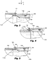
- FIGS. 3 - 8 various embodiments of the inner shaft 102 and the outer shaft 104 are shown.
- each of the figures described below shows only a single end portion of the drive shaft 100, it should be understood by someone of ordinary skill in the art that each of the connections described below can be have a mirror connection on an opposite end of the drive shaft.
- one end portion of the drive shaft could have a first type of connection and the other end portion of the drive shaft could have a second type of connection, and these connections could be selected from any one of the connections described and illustrated herein without departing from the spirt or scope of the subject application.
- FIG. 3 shows the inner shaft 102 directly connected to a sleeve 110 by fasteners 109.
- the fasteners here and in the following FIGS. 4-8 are distributed uniformly in the hoop direction due to axisymmetric geometry of the shaft design. Thus, a term "set" of connection fasteners is considered for description of their plurality in the hoop direction.
- the fasteners 109 can include, rivets, bolts, or welded connections, among others.
- the fasteners 109 constitute a single and only connection set between the inner shaft 102, the outer shafts 104, and the sleeve 110 in this embodiment.
- the inner shaft 102 includes a wider section 102a, and a narrower section 102b.
- the fasteners 109 are placed within the wider section 102a for making a connection to the sleeve 110 and the outer shaft 109.
- the sleeve 110 is placed on the outside of the outer shaft 104. Also shown is a representative ballistic projectile 140 directed at the shaft 100.
- FIG. 4 shows the inner shaft 102 directly connected to sleeve 110 by fasteners 109.
- the fasteners 109 also constitute a single and only connection set between the inner shaft 102, the outer shafts 104, and the sleeve 110.
- the outer shaft 104 is placed flush against a wider section 102a of the inner shaft 102, while the wider section 102a is placed flush against the sleeve 110.
- the sleeve 110 is placed inside of the wider portion 102a of the inner shaft 102, but it is located outside of the narrower section 102b of the inner shaft.
- FIG. 5 shows the inner shaft 102 and outer shaft 104 directly connected to sleeve 110 by fasteners 109.
- the fasteners 109 also constitute a single and only connection set between the inner shaft 102, the outer shaft 104, and the sleeve 110.
- the sleeve 110 is placed flush against a wider section 102a of the inner shaft 102, while the outer shaft 104 is placed flush against the sleeve 110.
- the sleeve 110 is placed outside of both the wider portion 102a of the inner shaft 102 and the narrower section 102b of the inner shaft.
- FIG. 6 shows an embodiment having two sleeves, an inner sleeve 112, and an outer sleeve 110.
- the inner shaft 102 connected to the inner sleeve 112 by fasteners 109b.
- the inner shaft 102 and the outer shaft 104 remain not connected directly.
- the outer shaft 104 is attached to the outer sleeve 110 by fasteners 109c.
- the inner sleeve 112 which includes a widening section 112a, is directly connected to the outer sleeve 110 by fasteners 109a.
- the wider section of the inner sleeve 112a is flush against the outer sleeve 110, while the narrower portion of the sleeve 112b is adjusted to an inner surface of the inner shaft 102.
- FIG. 7 shows an embodiment having a single narrowing sleeve 110 that has a wider section 110a and a narrower section 110b.
- the inner shaft 102 is connected to the narrower section 110b by fasteners 109b.
- the inner shaft 102 and the outer shaft 104 remain not connected directly.
- the outer shaft 104 is shown directly connected to the wider section of the sleeve 110a by fasteners 109a.
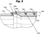
- FIG. 8 shows the inner shaft 102 directly connected to sleeve 110 by fasteners 109a and the outer shaft 104 connected to inner shaft by fasteners 109b.
- the outer shaft 104 is placed flush against a wider section 102a of the inner shaft 102, while the wider section 102a is placed flush against the sleeve 110.
- the sleeve 110 is placed inside of the wider portion 102a of the inner shaft 102, but is located outside of the narrower section 102b of the inner shaft.
- sleeves can be made of either metals or metallic alloys or fiber-reinforced polymer-matrix composites or their combinations.
- the connectors between the outer and inner shafts can be made of polymeric materials, fiber-reinforced polymer-matrix composites, metals or alloys or any of their combinations.
- a method of forming a drive shaft 100 includes defining an expected mission statement for a desired shaft, wherein the mission includes ballistic incidences, defining an expected ballistic cross-sectional size based on the ballistic incidences.
- the method further includes defining an inner shaft 102 having a first diameter (d1), defining an outer shaft 102 having a second diameter (d1), and defining a gap 106 between the inner surface of the outer shaft 104 and the outer surface of the inner shaft 102 wherein the gap 106 is larger than the cross-sectional size of the expected ballistic projectile.
Landscapes
- Engineering & Computer Science (AREA)
- General Engineering & Computer Science (AREA)
- Mechanical Engineering (AREA)
- Aviation & Aerospace Engineering (AREA)
- Ocean & Marine Engineering (AREA)
- Shafts, Cranks, Connecting Bars, And Related Bearings (AREA)
Abstract
Description
- The present disclosure relates generally to a drive shaft construction, and more specifically to design of drive shafts to withstand ballistic damage.
- Post-ballistic behavior of rotary-wing (helicopter) or fixed-wing aircraft drive shafts is critical to being able to operate in hostile environments and being able to finish missions. Specifically, in a situation after ballistic damage, a damaged drive shaft has to maintain structural and functional integrity sufficient to complete the flight mission including safe landing. Although conventional design methods have generally been considered satisfactory for their intended purpose, there is still a need in the art for improved drive shafts that can better withstand ballistic damage and, especially, post-ballistic behavior. Therefore, the disclosure is focused on an efficient design of a drive shaft, capable of providing desired structural integrity even in case of the ballistic damage.
- In a first aspect, there is provided a drive shaft including an outer shaft having a first diameter, an inner shaft concentric with the outer shaft having a second diameter, and a gap between an outer surface of the inner shaft and an inner surface of the outer shaft. The gap is designed to be larger than an expected projectile cross-section area. The inner shaft can be connected to at least a first sleeve.
- The outer shaft can be directly connected to at least a first sleeve. The inner shaft can be connected to a first sleeve, the outer shaft can be connected to a second sleeve, and the first and the second sleeves can be connected to each other. The inner shaft and outer shaft can be connected to each other, and the inner shaft can be connected to a sleeve, while the outer shaft can be not connected to the sleeve. The inner shaft and the outer shaft can be connected to each other, and the outer shaft can be connected to a sleeve while the first shaft is not connected to the sleeve. The inner shaft, the outer shaft, the first sleeve, and the second sleeve can be connected to each other. An inner surface of outer shaft can be connected to a first sleeve and an outer surface of the inner shaft can be connected to a second sleeve, and the inner surface of the outer shaft can be connected to the second sleeve and the outer surface of the outer shaft can be connected to a third sleeve, wherein each of the first, the second, and the third sleeves are each connected. The outer or the inner shaft can include a widening portion or a narrowing portion. The sleeve can include a widening or a narrowing portion.
- It is also contemplated that the outer shaft can be directly connected to at least a first sleeve. The inner shaft can directly connected to a first sleeve, while the outer shaft can be directly connected to a second sleeve, and the inner and the outer shafts can be indirectly connected to each other.
- It is further contemplated that the inner shaft and the outer shaft can be connected to each other, while the outer shaft can be flush against a sleeve where the first shaft does not contact the sleeve.
- It is also contemplated that a sleeve having a first diameter greater than the diameter of the inner shaft, and a second diameter smaller than the diameter of the inner shaft can be used to connect the shafts to the rotor.
- The drive shaft can include circumferential connectors between the inner shaft and the outer shaft. The connectors can include a portion extending axially and a portion extending radially.
- In a second aspect, there is provided a method of forming a drive shaft is also disclosed. The method includes defining an expected mission statement for a desired shaft, wherein the mission includes ballistic incidences, defining an expected ballistic diameter based on the ballistic incidences, defining an outer shaft having a first diameter, defining an inner shaft having a second diameter, and defining a gap between the inner surface of the outer shaft and the outer surface of the inner shaft, wherein the gap is larger than the diameter of the expected ballistic diameter. The mission plan may include more than one ballistic incidences, and expected ballistic diameter may be defined as a maximum value among expected ballistic diameters corresponding to different incidences. The inner shaft of the drive shaft and the outer shaft of the drive shaft may be formed of a fiber-reinforced polymer-matrix composite material or a metal or their combination. As would be appreciated, the method of the second aspect may form any of the drive shafts of the first aspect, described above.
- These and other features of the systems and methods of the subject disclosure will become more readily apparent to those skilled in the art from the following detailed description of the preferred embodiments taken in conjunction with the drawings.
- So that those skilled in the art to which the subject disclosure appertains will readily understand how to make and use the devices and methods of the subject disclosure without undue experimentation, embodiments thereof will be described in detail herein below with reference to certain figures, wherein:
-
FIG. 1 is a cross-sectional schematic view of an exemplary embodiment of an aircraft with a drive shaft on example of a rotary-wing aircraft vehicle (helicopter); -
FIG. 2 is a perspective sectional view of the drive shaft ofFIG. 1 , showing a gap between an inner shaft and an outer shaft; -
FIG. 3 is an axial cross-sectional view of a drive shaft ofFIG. 2 showing a first embodiment of the inner and outer shafts connected to a single sleeve; -
FIG. 4 is an axial cross-sectional view of a drive shaft ofFIG. 2 showing another embodiment of the inner and outer shafts connected to a single sleeve; -
FIG. 5 is an axial cross-sectional view of a drive shaft ofFIG. 2 showing another embodiment of the inner and outer shafts connected to a single sleeve; -
FIG. 6 is an axial cross-sectional view of a drive shaft ofFIG. 2 showing an embodiment of the inner and outer shafts along with two sleeves; -
FIG. 7 is an axial cross-sectional view of a drive shaft ofFIG. 2 showing another embodiment of the inner and outer shafts connected to a single sleeve; and -
FIG. 8 is an axial cross-sectional view of a drive shaft ofFIG. 2 showing another embodiment of the inner and outer shafts connected to a single sleeve. - Reference will now be made to the drawings wherein like reference numerals identify similar structural features or aspects of the subject disclosure. For purposes of explanation and illustration, and not limitation, a partial view of an exemplary embodiment of a drive shaft in accordance with the disclosure is shown in
FIG. 1 and is designated generally byreference character 100. Other embodiments of the drive shaft, and methods of making such shafts in accordance with the disclosure, or aspects thereof, are provided inFIGS. 2-8 , as will be described. The shafts, and methods of making such shafts described herein can be used for improving shaft reliability after ballistic damage. - Referring now to
FIG. 1 , a helicopter is shown having acomposite drive shaft 100 made of plural shaft elements or parts connecting a main rotor and a rear rotor. Thedrive shaft 100, shown in detail atFIG. 2 , is especially susceptible to ballistics from various sides and angles and can be damaged during missions. Maintaining structural and functional integrity sufficient to complete the flight mission including safe landing of the aircraft is of the upmost importance, as the aircraft cannot be operated once the structural integrity of the shaft is diminished. - Referring now to
FIG. 2 , a cross-section of thedrive shaft 100 is shown. Thedrive shaft 100 includes aninner shaft 102 having a first diameter (d1) and anouter shaft 104 concentric with theinner shaft 102 and having a second diameter (d2). Agap 106 is defined between the outside peripheral surface of theinner shaft 102 and the inner peripheral surface of theouter shaft 104. Theinner shaft 102 and theouter shaft 104 can be each formed of a fiber-reinforced polymer-matrix composite material or a metal or a metallic alloy or a combination thereof. Materials of the inner andouter shafts 102/104 can be the same or different from each other. - The
gap 106 is dimensionally designed to be larger than an expected projectile cross-sectional size that the helicopter could encounter on its mission, providing increased ballistic tolerance for the aircraft as compared to prior art drive shafts with one tubular body. After an expected mission statement or project statement is developed for the aircraft, where the statement includes possible ballistic incidences, an expected ballistic cross-sectional size, based on caliber, is defined. Thegap 106, is designed to be at least equal to the expected ballistic cross-sectional size, but taking safety factors into account the true gap is larger than the expected ballistic cross-sectional size. If the mission plan includes the potential to encounter more than one ballistic caliber, the expected ballistic cross-sectional size is defined based on the largest expected value of an expected ballistic cross-sectional size. - The
drive shaft 100 also includes an optional plurality ofcircumferential connectors 130 that are located between and contacting theinner shaft 102 and theouter shaft 104. Theconnectors 130 are configured as circumferential beams. The beams can have different cross-sectional shapes, including, for example, I-shape, L-shape, U-shape, double L-shape, among others. An example shown inFIG. 2 illustrates an embodiment in form of a I-shape beam. The connector beam can have different portions, including, for example, afirst portion 130a extending axially along the surface of theinner shaft 102, and asecond portion 130b extending axially along the surface of theouter shaft 104 and acentral web portion 131 extending radially betweenportions axial portions - Referring now to
FIGS. 3 - 8 , various embodiments of theinner shaft 102 and theouter shaft 104 are shown. Although each of the figures described below shows only a single end portion of thedrive shaft 100, it should be understood by someone of ordinary skill in the art that each of the connections described below can be have a mirror connection on an opposite end of the drive shaft. Alternatively, one end portion of the drive shaft could have a first type of connection and the other end portion of the drive shaft could have a second type of connection, and these connections could be selected from any one of the connections described and illustrated herein without departing from the spirt or scope of the subject application. -
FIG. 3 shows theinner shaft 102 directly connected to asleeve 110 byfasteners 109. The fasteners here and in the followingFIGS. 4-8 are distributed uniformly in the hoop direction due to axisymmetric geometry of the shaft design. Thus, a term "set" of connection fasteners is considered for description of their plurality in the hoop direction. In this and other embodiments of the subject application, thefasteners 109 can include, rivets, bolts, or welded connections, among others. Thefasteners 109 constitute a single and only connection set between theinner shaft 102, theouter shafts 104, and thesleeve 110 in this embodiment. Further shown, theinner shaft 102 includes awider section 102a, and anarrower section 102b. Thefasteners 109 are placed within thewider section 102a for making a connection to thesleeve 110 and theouter shaft 109. Thesleeve 110 is placed on the outside of theouter shaft 104. Also shown is a representativeballistic projectile 140 directed at theshaft 100. -
FIG. 4 shows theinner shaft 102 directly connected tosleeve 110 byfasteners 109. In this embodiment thefasteners 109 also constitute a single and only connection set between theinner shaft 102, theouter shafts 104, and thesleeve 110. Theouter shaft 104 is placed flush against awider section 102a of theinner shaft 102, while thewider section 102a is placed flush against thesleeve 110. Thesleeve 110 is placed inside of thewider portion 102a of theinner shaft 102, but it is located outside of thenarrower section 102b of the inner shaft. -
FIG. 5 shows theinner shaft 102 andouter shaft 104 directly connected tosleeve 110 byfasteners 109. In this embodiment thefasteners 109 also constitute a single and only connection set between theinner shaft 102, theouter shaft 104, and thesleeve 110. Thesleeve 110 is placed flush against awider section 102a of theinner shaft 102, while theouter shaft 104 is placed flush against thesleeve 110. Thesleeve 110 is placed outside of both thewider portion 102a of theinner shaft 102 and thenarrower section 102b of the inner shaft. -
FIG. 6 shows an embodiment having two sleeves, aninner sleeve 112, and anouter sleeve 110. Theinner shaft 102 connected to theinner sleeve 112 byfasteners 109b. Theinner shaft 102 and theouter shaft 104 remain not connected directly. Theouter shaft 104 is attached to theouter sleeve 110 byfasteners 109c. While theinner sleeve 112, which includes a wideningsection 112a, is directly connected to theouter sleeve 110 byfasteners 109a. The wider section of theinner sleeve 112a is flush against theouter sleeve 110, while the narrower portion of thesleeve 112b is adjusted to an inner surface of theinner shaft 102. -
FIG. 7 shows an embodiment having asingle narrowing sleeve 110 that has awider section 110a and anarrower section 110b. Theinner shaft 102 is connected to thenarrower section 110b byfasteners 109b. Theinner shaft 102 and theouter shaft 104 remain not connected directly. Theouter shaft 104 is shown directly connected to the wider section of thesleeve 110a byfasteners 109a. -
FIG. 8 shows theinner shaft 102 directly connected tosleeve 110 byfasteners 109a and theouter shaft 104 connected to inner shaft byfasteners 109b. Theouter shaft 104 is placed flush against awider section 102a of theinner shaft 102, while thewider section 102a is placed flush against thesleeve 110. Thesleeve 110 is placed inside of thewider portion 102a of theinner shaft 102, but is located outside of thenarrower section 102b of the inner shaft. - In the above examples (
FIGS. 3-8 ), sleeves can be made of either metals or metallic alloys or fiber-reinforced polymer-matrix composites or their combinations. The connectors between the outer and inner shafts can be made of polymeric materials, fiber-reinforced polymer-matrix composites, metals or alloys or any of their combinations. - A method of forming a
drive shaft 100 is also disclosed which includes defining an expected mission statement for a desired shaft, wherein the mission includes ballistic incidences, defining an expected ballistic cross-sectional size based on the ballistic incidences. The method further includes defining aninner shaft 102 having a first diameter (d1), defining anouter shaft 102 having a second diameter (d1), and defining agap 106 between the inner surface of theouter shaft 104 and the outer surface of theinner shaft 102 wherein thegap 106 is larger than the cross-sectional size of the expected ballistic projectile. - The methods and systems of the present disclosure, as described above and shown in the drawings, provide for a helicopter drive shaft capable of withstanding ballistic damage and operating as intended better than conventional drive shafts. Further benefits include, increased ballistic resilience in combat conditions, reduced weight, increased limit load or/and remaining flight life after a ballistic damage.
- While the apparatus and methods of the subject disclosure have been shown and described with reference to preferred embodiments, those skilled in the art will readily appreciate that changes and/or modifications may be made thereto without departing from the scope of the subject disclosure.
Claims (15)
- An aircraft drive shaft (100) comprising:an outer shaft (104) having a first diameter configured to couple a first gearbox and a second gearbox to provide power transfer between the two gearboxes;an inner shaft (102) concentric with the outer shaft (104) and having a second diameter configured to provide structural support to the outer shaft;a gap (106) defined between an outer peripheral surface of the inner shaft (102) and an inner peripheral surface of the outer shaft (104), wherein the gap (106) is sized according to a ballistic projectile cross-section size that the aircraft is considered to encounter on an upcoming mission; anda sleeve (110) located at least at first end of the outer shaft connecting the outer shaft to the inner shaft.
- The drive shaft of claim 1, further comprising a plurality of connectors (130) arranged axially or/and radially within the gap (106) between the inner shaft (102) and the outer shaft (104), wherein each connector (130) contacts the outer shaft and contacts the inner shaft, optionally
wherein each of the connectors includes at least one first portion extending axially and/or at least one second portion extending radially, and optionally wherein each of connectors extends 360 degrees circumferentially about the gap. - The drive shaft of claim 1 or 2, wherein the gap (106) is larger than an expected ballistic cross-section area.
- The drive shaft of any preceding claim, wherein the sleeve includes a first sleeve (112) and a second sleeve (110) and wherein the inner shaft (102) is directly connected to at least the first sleeve (112), and the outer shaft (104) is directly connected to at least the first sleeve, and/or wherein the inner shaft (102) is directly connected to the first sleeve (112), the outer shaft (104) is directly connected to the second sleeve (110), and the first sleeve (112) and the second sleeve (110) are connected to each other.
- The drive shaft of any preceding claim, wherein the inner shaft (102) and outer shaft (104) are directly connected to each other, and the inner shaft (102) or the outer shaft (104) is directly connected to the sleeve (110).
- The drive shaft of any preceding claim, wherein the inner shaft (102) and the outer shaft (104) are connected to each other, and the outer shaft (104) is flush against the sleeve (110) while the first shaft does not contact the sleeve (110).
- The drive shaft of any preceding claim, wherein the sleeve includes a first sleeve (112) and a second sleeve (110) and wherein the inner shaft (102), the outer shaft (104), the first sleeve (112), and the second sleeve (110) are connected to each other.
- The drive shaft of any preceding claim, wherein the sleeve (110) is at least partially located between the inner shaft (102) and the outer shaft (104).
- The drive shaft of any preceding claim, wherein the inner shaft (102) or/and the outer shaft (104) includes a widening portion or/and a narrowing portion.
- The drive shaft of any preceding claim, wherein the sleeve (110) connected to at least one of the shafts (102, 104) includes a widening portion or/and a narrowing portion.
- The drive shaft of claim 1, wherein the sleeve (110) is connected to at least a first gearbox.
- A method of forming a drive shaft (100) comprising:defining an expected mission statement for a desired shaft, wherein the mission statement includes ballistic incidences;defining an expected ballistic cross-sectional size related to the ballistic incidences;providing an outer shaft (104) having a surface defining an inner peripheral diameter;providing an inner shaft (102) having an outer surface defining an outer peripheral diameter; anddefining a gap (106) between the inner surface of the outer shaft (104) and the outer surface of the inner shaft (102), wherein the gap (106) is larger than the cross-sectional size of the expected ballistic diameter.
- The method of claim 12, wherein the mission plan includes more than one ballistic incidences, and expected ballistic cross-sectional size is defined as maximal value among expected ballistic cross-sectional sizes corresponding to different incidences, and/or
wherein the inner shaft (102) of the drive shaft (100) and the outer shaft (104) of the drive shaft are formed of the same or different fiber-reinforced polymer-matrix composite materials or metals or metallic alloys or their combination. - The method of forming the drive shaft of claim 2, wherein the sleeve is formed of the same or different metals or metallic alloys or fiber-reinforced polymer-matrix composites or their combination.
- The method of forming the drive shaft of claim 2, wherein the connector(s) are formed of the same or different polymers or metals or metallic alloys or fiber-reinforced polymer-matrix composites or their combination.
Applications Claiming Priority (1)
| Application Number | Priority Date | Filing Date | Title |
|---|---|---|---|
| US17/367,085 US12258122B2 (en) | 2021-07-02 | 2021-07-02 | Drive shaft with ballistic tolerance |
Publications (1)
| Publication Number | Publication Date |
|---|---|
| EP4112460A1 true EP4112460A1 (en) | 2023-01-04 |
Family
ID=82493911
Family Applications (1)
| Application Number | Title | Priority Date | Filing Date |
|---|---|---|---|
| EP22182397.4A Pending EP4112460A1 (en) | 2021-07-02 | 2022-06-30 | Drive shaft with increased ballistic tolerance |
Country Status (2)
| Country | Link |
|---|---|
| US (1) | US12258122B2 (en) |
| EP (1) | EP4112460A1 (en) |
Families Citing this family (1)
| Publication number | Priority date | Publication date | Assignee | Title |
|---|---|---|---|---|
| US11892035B2 (en) * | 2021-04-23 | 2024-02-06 | Hamilton Sundstrand Corporation | Composite/metal joints |
Citations (4)
| Publication number | Priority date | Publication date | Assignee | Title |
|---|---|---|---|---|
| EP0985837A2 (en) * | 1998-09-11 | 2000-03-15 | Dr.Ing. h.c.F. Porsche Aktiengesellschaft | Shaft, in particular drive shaft, guide arm, strut or similar |
| US20200063788A1 (en) * | 2018-08-24 | 2020-02-27 | Hamilton Sundstrand Corporation | Ballistic resistant drive shaft |
| EP3617066A1 (en) * | 2018-08-30 | 2020-03-04 | Bell Textron Inc. | Redundant impact-resistant structure |
| EP3628588A1 (en) * | 2018-09-28 | 2020-04-01 | Hamilton Sundstrand Corporation | Design and inspection method of aircraft drive shafts |
Family Cites Families (8)
| Publication number | Priority date | Publication date | Assignee | Title |
|---|---|---|---|---|
| US373339A (en) * | 1887-11-15 | Isidobe eskell cliffoed | ||
| US2890576A (en) * | 1957-04-15 | 1959-06-16 | Bentley & Sons Company A | Torque transmitting assembly |
| US3580214A (en) * | 1969-04-03 | 1971-05-25 | Ernest Muller | Marine propeller shafts bearing arrangements |
| US4127080A (en) * | 1977-03-08 | 1978-11-28 | Lakiza Rostislav I | Tubular shaft of a marine line shafting |
| US5724643A (en) | 1995-06-07 | 1998-03-03 | Allison Engine Company, Inc. | Lightweight high stiffness shaft and manufacturing method thereof |
| US6918839B2 (en) | 2002-01-28 | 2005-07-19 | The Boeing Company | Damage tolerant shaft |
| DE602005006782D1 (en) * | 2005-06-30 | 2008-06-26 | Agusta Spa | Improved helicopter gearboxes |
| WO2007070582A1 (en) | 2005-12-13 | 2007-06-21 | Gkn Driveline North America, Inc. | Shaft assembly |
-
2021
- 2021-07-02 US US17/367,085 patent/US12258122B2/en active Active
-
2022
- 2022-06-30 EP EP22182397.4A patent/EP4112460A1/en active Pending
Patent Citations (4)
| Publication number | Priority date | Publication date | Assignee | Title |
|---|---|---|---|---|
| EP0985837A2 (en) * | 1998-09-11 | 2000-03-15 | Dr.Ing. h.c.F. Porsche Aktiengesellschaft | Shaft, in particular drive shaft, guide arm, strut or similar |
| US20200063788A1 (en) * | 2018-08-24 | 2020-02-27 | Hamilton Sundstrand Corporation | Ballistic resistant drive shaft |
| EP3617066A1 (en) * | 2018-08-30 | 2020-03-04 | Bell Textron Inc. | Redundant impact-resistant structure |
| EP3628588A1 (en) * | 2018-09-28 | 2020-04-01 | Hamilton Sundstrand Corporation | Design and inspection method of aircraft drive shafts |
Also Published As
| Publication number | Publication date |
|---|---|
| US12258122B2 (en) | 2025-03-25 |
| US20230002039A1 (en) | 2023-01-05 |
Similar Documents
| Publication | Publication Date | Title |
|---|---|---|
| EP3069989B1 (en) | Lightweight propeller blade with improved retention capacity | |
| EP2893172B1 (en) | Assembly for mounting a turbine engine to a pylon | |
| US20220388695A1 (en) | Thrusting rails for launch vehicles, and associated systems and methods | |
| US10590801B2 (en) | Seal panel for a gas turbine engine | |
| US12258122B2 (en) | Drive shaft with ballistic tolerance | |
| US5398294A (en) | Track roller bearing | |
| CN110617745A (en) | Shear screw type cabin socket joint separating mechanism | |
| EP1409953B1 (en) | Bomb shroud | |
| EP3530974B1 (en) | Flexible coupling for a drive system | |
| EP4095406B1 (en) | Flexible coupling assembly | |
| CN110319093B (en) | Electromagnetic effect protective fastener with swageable termination body | |
| EP3583331B1 (en) | Gear for a transmission with inclined sidewalls | |
| US11608852B2 (en) | Slip-between-center propeller shaft assembly | |
| EP3486435B1 (en) | Fuse joint with fenestrated fuse pin | |
| EP0195150A1 (en) | Torque tube assembly | |
| EP0982561A2 (en) | Sabot anti-splitting ring | |
| US12312000B2 (en) | Intermediate shaft axial retention device | |
| EP3742006B1 (en) | Fused alignment pin | |
| US4739695A (en) | Fluid-pressure-operable actuator systems | |
| US11371549B2 (en) | Fastener joints with enhanced strength for composite components | |
| EP0098704A2 (en) | Helicopter rotors | |
| EP3081758B1 (en) | Aircraft engine fan assembly with a blade lock retainer | |
| EP4015856B1 (en) | Tail rotor actuator joint | |
| EP3875799B1 (en) | Silent block bushing | |
| EP3822164B1 (en) | Axial load capable torque tube assembly & manufacturing methods thereof |
Legal Events
| Date | Code | Title | Description |
|---|---|---|---|
| PUAI | Public reference made under article 153(3) epc to a published international application that has entered the european phase |
Free format text: ORIGINAL CODE: 0009012 |
|
| STAA | Information on the status of an ep patent application or granted ep patent |
Free format text: STATUS: THE APPLICATION HAS BEEN PUBLISHED |
|
| AK | Designated contracting states |
Kind code of ref document: A1 Designated state(s): AL AT BE BG CH CY CZ DE DK EE ES FI FR GB GR HR HU IE IS IT LI LT LU LV MC MK MT NL NO PL PT RO RS SE SI SK SM TR |
|
| STAA | Information on the status of an ep patent application or granted ep patent |
Free format text: STATUS: REQUEST FOR EXAMINATION WAS MADE |
|
| 17P | Request for examination filed |
Effective date: 20230630 |
|
| RBV | Designated contracting states (corrected) |
Designated state(s): AL AT BE BG CH CY CZ DE DK EE ES FI FR GB GR HR HU IE IS IT LI LT LU LV MC MK MT NL NO PL PT RO RS SE SI SK SM TR |
|
| P01 | Opt-out of the competence of the unified patent court (upc) registered |
Effective date: 20230922 |
|
| STAA | Information on the status of an ep patent application or granted ep patent |
Free format text: STATUS: EXAMINATION IS IN PROGRESS |
|
| 17Q | First examination report despatched |
Effective date: 20240619 |
|
| 17Q | First examination report despatched |
Effective date: 20240626 |