EP4112459A1 - Ejecting system, method and vehicle - Google Patents
Ejecting system, method and vehicle Download PDFInfo
- Publication number
- EP4112459A1 EP4112459A1 EP22180242.4A EP22180242A EP4112459A1 EP 4112459 A1 EP4112459 A1 EP 4112459A1 EP 22180242 A EP22180242 A EP 22180242A EP 4112459 A1 EP4112459 A1 EP 4112459A1
- Authority
- EP
- European Patent Office
- Prior art keywords
- magazine
- ejecting system
- dispensing means
- dispensing
- vehicle
- Prior art date
- Legal status (The legal status is an assumption and is not a legal conclusion. Google has not performed a legal analysis and makes no representation as to the accuracy of the status listed.)
- Granted
Links
Images




Classifications
-
- F—MECHANICAL ENGINEERING; LIGHTING; HEATING; WEAPONS; BLASTING
- F41—WEAPONS
- F41H—ARMOUR; ARMOURED TURRETS; ARMOURED OR ARMED VEHICLES; MEANS OF ATTACK OR DEFENCE, e.g. CAMOUFLAGE, IN GENERAL
- F41H11/00—Defence installations; Defence devices
- F41H11/02—Anti-aircraft or anti-guided missile or anti-torpedo defence installations or systems
-
- B—PERFORMING OPERATIONS; TRANSPORTING
- B64—AIRCRAFT; AVIATION; COSMONAUTICS
- B64D—EQUIPMENT FOR FITTING IN OR TO AIRCRAFT; FLIGHT SUITS; PARACHUTES; ARRANGEMENT OR MOUNTING OF POWER PLANTS OR PROPULSION TRANSMISSIONS IN AIRCRAFT
- B64D1/00—Dropping, ejecting, releasing or receiving articles, liquids, or the like, in flight
- B64D1/02—Dropping, ejecting, or releasing articles
-
- B—PERFORMING OPERATIONS; TRANSPORTING
- B64—AIRCRAFT; AVIATION; COSMONAUTICS
- B64D—EQUIPMENT FOR FITTING IN OR TO AIRCRAFT; FLIGHT SUITS; PARACHUTES; ARRANGEMENT OR MOUNTING OF POWER PLANTS OR PROPULSION TRANSMISSIONS IN AIRCRAFT
- B64D1/00—Dropping, ejecting, releasing or receiving articles, liquids, or the like, in flight
- B64D1/02—Dropping, ejecting, or releasing articles
- B64D1/08—Dropping, ejecting, or releasing articles the articles being load-carrying devices
- B64D1/12—Releasing
-
- B—PERFORMING OPERATIONS; TRANSPORTING
- B64—AIRCRAFT; AVIATION; COSMONAUTICS
- B64D—EQUIPMENT FOR FITTING IN OR TO AIRCRAFT; FLIGHT SUITS; PARACHUTES; ARRANGEMENT OR MOUNTING OF POWER PLANTS OR PROPULSION TRANSMISSIONS IN AIRCRAFT
- B64D7/00—Arrangement of military equipment, e.g. armaments, armament accessories or military shielding, in aircraft; Adaptations of armament mountings for aircraft
-
- B—PERFORMING OPERATIONS; TRANSPORTING
- B64—AIRCRAFT; AVIATION; COSMONAUTICS
- B64D—EQUIPMENT FOR FITTING IN OR TO AIRCRAFT; FLIGHT SUITS; PARACHUTES; ARRANGEMENT OR MOUNTING OF POWER PLANTS OR PROPULSION TRANSMISSIONS IN AIRCRAFT
- B64D7/00—Arrangement of military equipment, e.g. armaments, armament accessories or military shielding, in aircraft; Adaptations of armament mountings for aircraft
- B64D7/02—Arrangement of military equipment, e.g. armaments, armament accessories or military shielding, in aircraft; Adaptations of armament mountings for aircraft the armaments being firearms
- B64D7/04—Arrangement of military equipment, e.g. armaments, armament accessories or military shielding, in aircraft; Adaptations of armament mountings for aircraft the armaments being firearms fixedly mounted
-
- F—MECHANICAL ENGINEERING; LIGHTING; HEATING; WEAPONS; BLASTING
- F41—WEAPONS
- F41F—APPARATUS FOR LAUNCHING PROJECTILES OR MISSILES FROM BARRELS, e.g. CANNONS; LAUNCHERS FOR ROCKETS OR TORPEDOES; HARPOON GUNS
- F41F3/00—Rocket or torpedo launchers
- F41F3/04—Rocket or torpedo launchers for rockets
- F41F3/06—Rocket or torpedo launchers for rockets from aircraft
-
- F—MECHANICAL ENGINEERING; LIGHTING; HEATING; WEAPONS; BLASTING
- F42—AMMUNITION; BLASTING
- F42B—EXPLOSIVE CHARGES, e.g. FOR BLASTING, FIREWORKS, AMMUNITION
- F42B12/00—Projectiles, missiles or mines characterised by the warhead, the intended effect, or the material
- F42B12/02—Projectiles, missiles or mines characterised by the warhead, the intended effect, or the material characterised by the warhead or the intended effect
- F42B12/36—Projectiles, missiles or mines characterised by the warhead, the intended effect, or the material characterised by the warhead or the intended effect for dispensing materials; for producing chemical or physical reaction; for signalling ; for transmitting information
- F42B12/56—Projectiles, missiles or mines characterised by the warhead, the intended effect, or the material characterised by the warhead or the intended effect for dispensing materials; for producing chemical or physical reaction; for signalling ; for transmitting information for dispensing discrete solid bodies
- F42B12/70—Projectiles, missiles or mines characterised by the warhead, the intended effect, or the material characterised by the warhead or the intended effect for dispensing materials; for producing chemical or physical reaction; for signalling ; for transmitting information for dispensing discrete solid bodies for dispensing radar chaff or infrared material
-
- F—MECHANICAL ENGINEERING; LIGHTING; HEATING; WEAPONS; BLASTING
- F42—AMMUNITION; BLASTING
- F42B—EXPLOSIVE CHARGES, e.g. FOR BLASTING, FIREWORKS, AMMUNITION
- F42B5/00—Cartridge ammunition, e.g. separately-loaded propellant charges
- F42B5/02—Cartridges, i.e. cases with charge and missile
- F42B5/145—Cartridges, i.e. cases with charge and missile for dispensing gases, vapours, powders, particles or chemically-reactive substances
- F42B5/15—Cartridges, i.e. cases with charge and missile for dispensing gases, vapours, powders, particles or chemically-reactive substances for creating a screening or decoy effect, e.g. using radar chaff or infrared material
-
- F—MECHANICAL ENGINEERING; LIGHTING; HEATING; WEAPONS; BLASTING
- F41—WEAPONS
- F41A—FUNCTIONAL FEATURES OR DETAILS COMMON TO BOTH SMALLARMS AND ORDNANCE, e.g. CANNONS; MOUNTINGS FOR SMALLARMS OR ORDNANCE
- F41A9/00—Feeding or loading of ammunition; Magazines; Guiding means for the extracting of cartridges
- F41A9/01—Feeding of unbelted ammunition
- F41A9/24—Feeding of unbelted ammunition using a movable magazine or clip as feeding element
-
- F—MECHANICAL ENGINEERING; LIGHTING; HEATING; WEAPONS; BLASTING
- F41—WEAPONS
- F41A—FUNCTIONAL FEATURES OR DETAILS COMMON TO BOTH SMALLARMS AND ORDNANCE, e.g. CANNONS; MOUNTINGS FOR SMALLARMS OR ORDNANCE
- F41A9/00—Feeding or loading of ammunition; Magazines; Guiding means for the extracting of cartridges
- F41A9/35—Feeding multibarrel guns
Definitions
- the present disclosure relates to an ejecting system, a vehicle comprising such an ejecting system and a method for preparing at least one magazine for a countermeasure operation from said ejecting system.
- Ejecting systems are commonly used to dispense countermeasures from vehicles, specifically from aircrafts. For instance, helicopters, transport and fast jet aircraft may be provided with various types of ejecting systems for dispensing countermeasure means.
- Such countermeasure means may comprise radar reflecting aluminized foil, free-fall radio frequency jammers and hot IR decoys to confuse and divert any means that may be targeted towards the vehicle.
- Major parts of the ejecting systems and specifically their magazines are often enclosed in capsules or cases arranged under the wings, in or under the fuselage of a vehicle. Specifically, the ejecting systems and major parts thereof are fixed mounted in a fixed dispensing direction.
- the dispensing operation is used only when the vehicle is exposed for threats.
- the dispensing unit may be inactivated during a long period of time.
- the countermeasures within the dispenser unit might be exposed to air flow and water or particles in the air flow which may come into the parts of the ejecting system and reach the countermeasures, and as a result damage the countermeasures.
- dispensing units arranged externally contribute to increased aerodynamic drag and increased radar cross section.
- ejecting systems in the market today are usually loaded with expendables prior to flight and cannot be re-loaded during a flight.
- the ejecting system has a limited amount of expendables which may result in that a vehicle is susceptible to threats when said expendables are dispensed.
- the present disclosure is at least partly based on the insight that by providing an improved ejecting system with focus on loading efficiency, compactness and flexibility, the ejecting systems will be improved in terms of having a better performance (by the flexibility and compactness) and provide enhanced endurance (by being reloadable).
- the present disclosure provides an ejecting system for dispensing countermeasure comprising at least one magazine comprising at least one expendable cartridge, wherein the at least one magazine comprises a transporting rack extending in a first direction. Further, the ejecting system comprises a magazine feeding mechanism arranged to cooperate with said transporting rack to move each of the at least one magazines from a stored position to a loaded position. Further, the ejecting system comprises a dispensing means arranged to hold at least one magazine when said at least one magazine is in a loaded position, wherein the dispensing means comprises an electrical connector arrangement attachable to said magazine.
- the ejecting system comprises a first positioning mechanism arranged to move said dispensing means and the at least one magazine from the loaded position to a protruding position.
- a benefit of the present disclosure is that the ejecting system is able to reload the dispensing means by said feeding mechanism. After the expandable cartridges are dispensed, additional magazines may be fed in to the dispensing means.
- the ejecting system is compact and may be fully mounted inside a vehicle by having a positioning mechanism that may protrude the dispensing means. Consequently, the ejecting system does not contribute to aerodynamic drag or radar cross section when not in use.
- the at least one magazine may move along a second direction essentially perpendicular to the first direction. It should be noted that the second direction may in some embodiments have an angle of 0-90 degrees relative the first direction.
- the dispensing means may comprises an eccentric mechanism arranged to, by engaging to said transporting rack, attach said magazine to said electrical connector arrangement.
- the eccentric mechanism is arranged to attach said magazine to said electrical connector arrangement without association to said transporting rack.
- the eccentric mechanism allows for a convenient igniting means for a plurality of expandable cartridges.
- the electrical connector arrangement may ignite expandable countermeasures in each of said expandable cartridges. Further, the electrical connector arrangement may determine the number of expandable cartridges that are available in a magazine. Further, the electrical connector arrangement may, based on a control signal, ignite at least one expandable cartridge.
- a dispensing means may attach the electrical connector arrangement to said magazine.
- the magazine feeding mechanism and said transporting rack may cooperate/engage by means of a rack and pinion mechanism, wherein the magazine feeding mechanism comprises at least one rotating pinion engaging with a corresponding linear gear on said transporting rack.
- a benefit of this is that it provides an efficient mechanism for feeding magazines to said dispensing means allowing for a convenient reloading of the dispensing means.
- Each magazine may comprises a connector contact surface and an opposing dispensing surface.
- the connector contact surface may be arranged to contact connector pins so to allow for igniting the expendable cartridges in the magazine and the dispensing surface allows for dispensing the expendable cartridges.
- Each magazine may comprises a first axis extending along the first direction and a second axis extending in a second direction, wherein said dispensing means comprises a second positioning mechanism configured to, when in said protruding position, rotate said magazine about at least one of the first and the second axis.
- the first axis may be a transversal axis of said magazine extending transversally along the transporting rack, wherein the second axis may be predominantly perpendicular to the first axis and extending from a dispensing surface to a connector contact surface.
- the rotation allows for flexibility in the dispensing direction of the countermeasures.
- the dispensing surface may be angled and aimed at any suitable position.
- the ejecting system may comprise a hatch, enclosing at least the dispensing means within a storage compartment, the hatch being configured to be open when said dispensing means is in a protruded position and to close when said dispensing means is in an initial position.
- the dispensing means may comprise a bracket and a magazine housing adapted to hold said magazine, and wherein the magazine housing is provided with a launch opening (on said dispensing surface), wherein said second positioning mechanism is arranged to rotate the bracket with respect to a first rotational axis, and rotate the magazine housing with respect to a second rotational axis.
- the first rotational axis may be conjoined with the second axis of said magazine when said dispensing means holds said magazine, and wherein the second rotational axis may be conjoined with said first axis of said magazine when said dispensing means holds said magazine.
- the dispensing means may rotate the magazine with 2 degrees of freedom.
- the first positioning mechanism may further be arranged to retract the dispensing means to an initial position after a dispensing operation so to allow additional of the plurality of magazines to move from a stored position to a loaded position.
- a benefit of this is that it allows for reloading of the dispensing means with additional magazines after a dispensing operation has been performed.
- the at least one expandable may comprise expendable countermeasure.
- the at least one magazine is, when in said storing position, arranged along a common row in a storage compartment extending in said first direction towards said dispensing means (6).
- the magazines are in close connection to said dispensing means allowing for a rapid reloading.
- the magazines may be arranged along several rows,
- the ejecting system may be fully enclosed in a storage compartment (in a body of e.g. a vehicle), wherein said storage compartment comprises a hatch, enclosing at least the dispensing means within said storage compartment, the hatch being configured open in order to allow said dispensing means to move into a protruded position.
- a storage compartment in a body of e.g. a vehicle
- said storage compartment comprises a hatch, enclosing at least the dispensing means within said storage compartment, the hatch being configured open in order to allow said dispensing means to move into a protruded position.
- a benefit of this is that the hatch allows for the ejecting system to be arranged in a compact manner in e.g. a vehicle. Further, allows the ejecting system to be implemented so to be hidden from an exterior of e.g. the body of a vehicle.
- the said magazines may be provided in a storage compartment inside the body of said vehicle when in said storing position and in said loaded position, and wherein a magazine (loaded in the dispensing means) protrude outwardly from an opening of said body when in said protruded position.
- a large quantity of magazines may be stored in a storage compartment inside the body of said vehicle and be loaded on the dispensing means automatically after each dispensing operation.
- the opening may be enclosed by a hatch (or a door means) when in said storing position and in said loaded position, wherein said hatch is opened in said protruded position.
- the method comprises the steps of: Firstly, actuating the magazine feeding mechanism, so to transport the at least one magazine in a first direction. Further, the dispensing means receives the at least one magazine. Further, the ejecting system locks the magazine in said dispensing means, wherein the electrical connector arrangement engages with said magazine. Further, the ejecting system movies the magazine, by means of said first positioning mechanism, to said protruded position. Moreover, the dispensing means may in some embodiments herein comprise the step of rotating said magazine about at least one of a first and a second axis of the magazine.
- the method may interchangeably also be directed to "A method for preparing an ejecting system for a countermeasure operation".
- the method allows the magazines to be loaded to said dispensing means and angled at a desired direction prior to being ignited by the connector arrangement.
- the method may further comprising the step of, preceding moving the magazine to said protruding position, opening a hatch enclosing said dispensing means within a compartment.
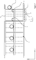
- Figure 1 illustrates an ejecting system 1 for dispensing countermeasure from a cut-out top cross sectional view.
- the ejecting system 1 comprises at least one magazine 2 comprising at least one expendable cartridge 3, wherein each the at least one magazine 2 comprises a transporting rack 4 extending in a first direction D1. Further, the magazine feeding mechanism 5 is arranged to cooperate with said transporting rack 4 to move each of the at least one magazines 2 from a stored position to a loaded position.
- a loaded position may refer to that a magazine is held by a dispensing means 6.
- all magazines 2 are in a stored position.
- the ejecting system 1 also comprises a dispensing means 6 arranged to hold said at least one magazine 2 when said at least one magazine 2 is in a loaded position (not shown in Figure 1 , seen in Figure 2 ).
- the magazines 2 are all in a stored position (seen by that the dispensing means 6 is not holding a magazine 2). Further, the dispensing means 6 comprises an electrical connector arrangement 7 attachable to each of said at least one magazine 2.
- the ejecting system 1 further comprises a first positioning mechanism 8 arranged to move said dispensing means 6 and the at least one magazine 2 from the loaded position to a protruding position (shown in Figure 3 ) allowing for dispensing countermeasures away from the ejecting system 1.
- Figure 1 further shows that the ejecting system 1 may be arranged inside a storage compartment 21 in a body 22 (of e.g. a vehicle) it should be noted that the ejecting system 1 is not necessary arranged in a compartment in a body 22.
- the storage compartment 21 also may comprise a hatch 12, enclosing at least the dispensing means 6 within said storage compartment 21, the hatch 12 being configured open in order to allow said dispensing means 6 to move into a protruded position (not shown in Figure 1 , seen in Figure 3 ).
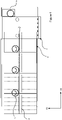
- Figure 2 illustrates an ejecting system 1 for dispensing countermeasure from a cut-out cross sectional view, wherein the ejecting system 1 comprises a plurality of magazines 2, wherein one magazine 2 is in a loaded position in the dispensing means 6.
- Figure 2 illustrates that the dispensing means 6 may comprise an eccentric mechanism 9 arranged to, by engaging to said transporting rack 4, attach said magazine 2 to said electrical connector arrangement 7.
- the dispensing means 6 may according to some embodiments comprise an eccentric mechanism 9 arranged to attach said magazine 2 to said electrical connector arrangement 7.
- the eccentric mechanism 8 may apply a force to overcome said spring force in order to attach the magazine 2 to said connector arrangement 7.
- Figure 2 shows that there is a distance L1, between the magazine 2 in the loaded position and the connector arrangement 7, thus the eccentric mechanism 9 has not yet applied a force so to attach the magazine to said connector arrangement 7.
- Figure 1 and 2 shows that the magazine feeding mechanism 5 and said transporting rack 4 may cooperate/engage by means of a rack and pinion mechanism, wherein the magazine feeding mechanism 5 comprises at least one rotating pinion engaging with a corresponding linear gear 4' on said transporting rack 4.
- each magazine 2 comprises a connector contact surface 14 and an opposing dispensing surface 13.
- the connector contact surface 14 is adapted to be attached to a connector arrangement 7 and the dispensing surface 13 may comprise launch openings so to dispense the expendable cartridges 3.
- each magazine may hold e.g. 1-50 expendable cartridges 3.
- the electrical connector arrangement 7 comprises a plurality of electrical pins attachable to each of the plurality of expendable cartridges 3.
- at least one electrical pin is attachable to each expendable cartridge 2 in a magazine 2.
- the electrical connector arrangement 7 may be connected to control circuitry 16 configured to determine the amount of disposable cartridges 3 in a magazine 2. Further, control circuitry 16 may transmit ignition signals to ignite each expandable cartridge 3 separately.
- the control circuitry 16 may comprise, for example, one or more central processing units (CPUs), dedicated to performing calculations, and/or other processing devices.
- the at least one magazine 2 is, when in said storing position, arranged along a common row in a storage compartment 21 extending in said first direction D1 towards said dispensing means 6.
- the magazines 2 may be arranged in a plurality of rows according to some embodiments.
- Figure 3 illustrates an ejecting system 1 for dispensing countermeasure from a cut-out cross sectional view, wherein a magazine 2 and a dispensing means 6 are in a protruded position.
- the positioning mechanism 8 has moved the dispensing means 6 (and consequently the magazine 2) from a loaded position to a protruded position.
- the magazine 2 may in the protruded position perform a dispensing operation so to dispense countermeasures in said expandable cartridges.
- the first positioning mechanism 8 may be arranged to retract the dispensing means 6 to an initial position after a dispensing operation so to allow additional of the plurality of magazines 2 to move from a stored position to a loaded position. Thus, allowing the dispensing means to be reloaded.
- Figure 4 shows a cross sectional view of the ejecting system 1 where a magazine 2 is transitioning from a stored position to a loaded position by means of the transporting rack 4 engaging with the magazine feeding mechanism 5.
- Figure 5 shows a cross sectional view of the ejecting system 1 where the dispensing means 6 holding a magazine 2 is transitioning from a loaded position to a protruded position, by engagement of the first positioning mechanism 8 with said magazine 2.
- Figure 6A illustrates an objective view of a magazine 3, showing that the magazine 2 comprises a first axis x1 extending along the first direction D1 and a second axis x2 extending in a second direction D2.
- Figure 6B shows the magazine 2 in Figure 6A from a side view.
- Figure 7A and 7B shows objective views of the dispensing means in a protruded position (protruding form a body of e.g. a vehicle) in accordance with some aspects of the present disclosure.
- the dispensing means 6 may comprises a bracket 15 and a magazine housing 10 adapted to hold said magazine 2 (thus a magazine 2 in a loaded position), and wherein the magazine housing 10 is provided with a launch opening 11, wherein said second positioning mechanism 8' is arranged to rotate the bracket 15 with respect to a first rotational axis r1, and rotate the magazine housing 10 with respect to a second rotational axis r2.
- said dispensing means 6 may be configured to, when in said protruding position, rotate said magazine 2 about at least one of the first and the second axis x1, x2 of the magazine. Further, the dispensing means 6 is when holding a magazine arranged so that the first rotation axis r1 is conjoined with the first axis x1 of the magazine, and such that the second rotational axis r2 is conjoined with the second axis x2 of the magazine.
- Figure 8 shows a vehicle 12 comprising the ejecting system 1 in accordance with any of the aspects of the present disclosure.
- the vehicle 20 is an airborne vehicle.
- the vehicle may be a ground-vehicle or a ship.
- the ejecting system may be arranged in a fixed installation.
- the magazines may be provided in a storage compartment 21 inside the body 22 of said vehicle 20 when in said storing position and in said loaded position, and wherein a magazine (and consequently at least a part of said dispensing system) protrude outwardly from an opening of said body 22 when in said protruded position.
- the opening may be enclosed by a hatch 12 when in said storing position and in said loaded position, wherein said hatch is opened in said protruded position.
- Figure 9 illustrates a method 100 for preparing at least one magazine for a countermeasure operation from an ejecting system in accordance with the present disclosure, wherein the method comprises the steps of actuating 101 the magazine feeding mechanism, so to transport the at least one magazine in a first direction. Further, the method comprises the step of receiving 102, in said dispensing means, the at least one magazine. Further, the method comprises the step of locking 103 the magazine in said dispensing means, wherein the electrical connector arrangement engages with said magazine. Further, the method comprises moving 104 the magazine, by means of said first positioning mechanism, to said protruded position.
- the method 100 may in some aspects herein comprise the step of rotating 105 said magazine, by means of said dispensing mechanism, about at least one of a first and a second axis of the magazine (see e.g. Figure 7B ).
- the method 100 may also comprise the step of preceding moving 104 the magazine to said protruding position, opening 103' a hatch enclosing said dispensing means within a compartment.
- the electrical connector arrangement may, after locking 103 or after rotating 105, control 106 (by means of the connector arrangement) the amount of disposable countermeasure cartridges in said magazine.
- control 106 by means of the connector arrangement
- the method 100 may control the amount of cartridges left to dispose in an upcoming countermeasure operation.
Landscapes
- Engineering & Computer Science (AREA)
- Aviation & Aerospace Engineering (AREA)
- General Engineering & Computer Science (AREA)
- Radar, Positioning & Navigation (AREA)
- Remote Sensing (AREA)
- Chemical & Material Sciences (AREA)
- Combustion & Propulsion (AREA)
- Warehouses Or Storage Devices (AREA)
- Preparation Of Compounds By Using Micro-Organisms (AREA)
- Automobile Manufacture Line, Endless Track Vehicle, Trailer (AREA)
Abstract
Description
- The present disclosure relates to an ejecting system, a vehicle comprising such an ejecting system and a method for preparing at least one magazine for a countermeasure operation from said ejecting system.
- Ejecting systems are commonly used to dispense countermeasures from vehicles, specifically from aircrafts. For instance, helicopters, transport and fast jet aircraft may be provided with various types of ejecting systems for dispensing countermeasure means. Such countermeasure means may comprise radar reflecting aluminized foil, free-fall radio frequency jammers and hot IR decoys to confuse and divert any means that may be targeted towards the vehicle.
- Major parts of the ejecting systems and specifically their magazines are often enclosed in capsules or cases arranged under the wings, in or under the fuselage of a vehicle. Specifically, the ejecting systems and major parts thereof are fixed mounted in a fixed dispensing direction.
- However, the dispensing operation is used only when the vehicle is exposed for threats. Thus, the dispensing unit may be inactivated during a long period of time. Under such period the countermeasures within the dispenser unit might be exposed to air flow and water or particles in the air flow which may come into the parts of the ejecting system and reach the countermeasures, and as a result damage the countermeasures. Moreover, dispensing units arranged externally contribute to increased aerodynamic drag and increased radar cross section. Further, ejecting systems in the market today are usually loaded with expendables prior to flight and cannot be re-loaded during a flight. Thus, the ejecting system has a limited amount of expendables which may result in that a vehicle is susceptible to threats when said expendables are dispensed.
- Based on the above, there is in the present art room for improvements in order to have ejecting systems that allow for a compact arrangement in a vehicle, efficient loading of the ejecting systems with expendables (so to prepare a dispensing operation), and a flexible dispensing mechanism that allow for handling of a larger quantity of expendables.
- Thus, there is room for ejecting systems in the present art to explore the domain to provide improved ejecting systems that are able to be compactly mounted in a vehicle that can handle a great quantity of magazines with expendables, that are flexible in dispensing and that are efficient in the loading.
- Even though some currently known solutions work well in some situations it would be desirable to provide an ejecting system that specifically fulfils requirements relating to efficiency, flexibility and compactness.
- It is therefore an object of the present disclosure to provide an ejecting system, a vehicle comprising an ejecting system and a method for preparing at least one magazine for a countermeasure operation from an ejecting system to mitigate, alleviate or eliminate one or more of the above-identified deficiencies and disadvantages.
- This object is achieved by means of methods, a vehicle, and an ejecting system as defined in the appended
claims - The present disclosure is at least partly based on the insight that by providing an improved ejecting system with focus on loading efficiency, compactness and flexibility, the ejecting systems will be improved in terms of having a better performance (by the flexibility and compactness) and provide enhanced endurance (by being reloadable).
- The present disclosure provides an ejecting system for dispensing countermeasure comprising at least one magazine comprising at least one expendable cartridge, wherein the at least one magazine comprises a transporting rack extending in a first direction. Further, the ejecting system comprises a magazine feeding mechanism arranged to cooperate with said transporting rack to move each of the at least one magazines from a stored position to a loaded position. Further, the ejecting system comprises a dispensing means arranged to hold at least one magazine when said at least one magazine is in a loaded position, wherein the dispensing means comprises an electrical connector arrangement attachable to said magazine.
- Moreover, the ejecting system comprises a first positioning mechanism arranged to move said dispensing means and the at least one magazine from the loaded position to a protruding position.
- A benefit of the present disclosure is that the ejecting system is able to reload the dispensing means by said feeding mechanism. After the expandable cartridges are dispensed, additional magazines may be fed in to the dispensing means.
- Further, the ejecting system is compact and may be fully mounted inside a vehicle by having a positioning mechanism that may protrude the dispensing means. Consequently, the ejecting system does not contribute to aerodynamic drag or radar cross section when not in use.
- Upon transitioning said dispensing means and the at least one magazine from the loaded position to the protruding position, the at least one magazine may move along a second direction essentially perpendicular to the first direction. It should be noted that the second direction may in some embodiments have an angle of 0-90 degrees relative the first direction.
- The dispensing means may comprises an eccentric mechanism arranged to, by engaging to said transporting rack, attach said magazine to said electrical connector arrangement. However, in some embodiments, the eccentric mechanism is arranged to attach said magazine to said electrical connector arrangement without association to said transporting rack.
- The eccentric mechanism allows for a convenient igniting means for a plurality of expandable cartridges.
- The electrical connector arrangement may ignite expandable countermeasures in each of said expandable cartridges. Further, the electrical connector arrangement may determine the number of expandable cartridges that are available in a magazine. Further, the electrical connector arrangement may, based on a control signal, ignite at least one expandable cartridge.
- Thus after a dispensing means received a magazine, it may attach the electrical connector arrangement to said magazine.
- The magazine feeding mechanism and said transporting rack may cooperate/engage by means of a rack and pinion mechanism, wherein the magazine feeding mechanism comprises at least one rotating pinion engaging with a corresponding linear gear on said transporting rack.
- A benefit of this is that it provides an efficient mechanism for feeding magazines to said dispensing means allowing for a convenient reloading of the dispensing means.
- Each magazine may comprises a connector contact surface and an opposing dispensing surface. The connector contact surface may be arranged to contact connector pins so to allow for igniting the expendable cartridges in the magazine and the dispensing surface allows for dispensing the expendable cartridges.
- Each magazine may comprises a first axis extending along the first direction and a second axis extending in a second direction, wherein said dispensing means comprises a second positioning mechanism configured to, when in said protruding position, rotate said magazine about at least one of the first and the second axis. The first axis may be a transversal axis of said magazine extending transversally along the transporting rack, wherein the second axis may be predominantly perpendicular to the first axis and extending from a dispensing surface to a connector contact surface.
- The rotation allows for flexibility in the dispensing direction of the countermeasures. Thus, the dispensing surface may be angled and aimed at any suitable position.
- The ejecting system may comprise a hatch, enclosing at least the dispensing means within a storage compartment, the hatch being configured to be open when said dispensing means is in a protruded position and to close when said dispensing means is in an initial position.
- The dispensing means may comprise a bracket and a magazine housing adapted to hold said magazine, and wherein the magazine housing is provided with a launch opening (on said dispensing surface), wherein said second positioning mechanism is arranged to rotate the bracket with respect to a first rotational axis, and rotate the magazine housing with respect to a second rotational axis. The first rotational axis may be conjoined with the second axis of said magazine when said dispensing means holds said magazine, and wherein the second rotational axis may be conjoined with said first axis of said magazine when said dispensing means holds said magazine. In other words, the dispensing means may rotate the magazine with 2 degrees of freedom.
- The first positioning mechanism may further be arranged to retract the dispensing means to an initial position after a dispensing operation so to allow additional of the plurality of magazines to move from a stored position to a loaded position.
- A benefit of this is that it allows for reloading of the dispensing means with additional magazines after a dispensing operation has been performed.
- The at least one expandable may comprise expendable countermeasure.
- The at least one magazine is, when in said storing position, arranged along a common row in a storage compartment extending in said first direction towards said dispensing means (6). Thus, the magazines are in close connection to said dispensing means allowing for a rapid reloading. The magazines may be arranged along several rows,
- The ejecting system may be fully enclosed in a storage compartment (in a body of e.g. a vehicle), wherein said storage compartment comprises a hatch, enclosing at least the dispensing means within said storage compartment, the hatch being configured open in order to allow said dispensing means to move into a protruded position.
- A benefit of this is that the hatch allows for the ejecting system to be arranged in a compact manner in e.g. a vehicle. Further, allows the ejecting system to be implemented so to be hidden from an exterior of e.g. the body of a vehicle.
- There is further provided a vehicle comprising the ejecting system in accordance with the present disclosure.
- The said magazines may be provided in a storage compartment inside the body of said vehicle when in said storing position and in said loaded position, and wherein a magazine (loaded in the dispensing means) protrude outwardly from an opening of said body when in said protruded position.
- Thus, a large quantity of magazines may be stored in a storage compartment inside the body of said vehicle and be loaded on the dispensing means automatically after each dispensing operation.
- The opening may be enclosed by a hatch (or a door means) when in said storing position and in said loaded position, wherein said hatch is opened in said protruded position. Thus, allowing for the ejecting system to be integrated within a body of a vehicle without contributing to aerodynamic drag or radar cross section when not in use.
- There is further disclosed a method for preparing at least one magazine for a countermeasure operation from an ejecting system in accordance with any aspect herein, wherein the method comprises the steps of: Firstly, actuating the magazine feeding mechanism, so to transport the at least one magazine in a first direction. Further, the dispensing means receives the at least one magazine. Further, the ejecting system locks the magazine in said dispensing means, wherein the electrical connector arrangement engages with said magazine. Further, the ejecting system movies the magazine, by means of said first positioning mechanism, to said protruded position. Moreover, the dispensing means may in some embodiments herein comprise the step of rotating said magazine about at least one of a first and a second axis of the magazine.
- I should be noted that the method may interchangeably also be directed to "A method for preparing an ejecting system for a countermeasure operation".
- Thus the method allows the magazines to be loaded to said dispensing means and angled at a desired direction prior to being ignited by the connector arrangement.
- The method may further comprising the step of, preceding moving the magazine to said protruding position, opening a hatch enclosing said dispensing means within a compartment.
- In the following the disclosure will be described in a non-limiting way and in more detail with reference to exemplary embodiments illustrated in the enclosed drawings, in which:
- Figure 1
- illustrates an
ejecting system 1 for dispensing countermeasure from a cut-out top cross sectional view in accordance with an embodiment of the present disclosure; - Figure 2
- illustrates an
ejecting system 1 for dispensing countermeasure from a cut-out top cross sectional view, where amagazine 2 is in a loaded position in accordance with an embodiment of the present disclosure; - Figure 3
- illustrates an
ejecting system 1 for dispensing countermeasure from a cut-out top cross sectional view, where amagazine 2 is in a protruded position in accordance with an embodiment of the present disclosure; - Figure 4
- illustrates an
ejecting system 1 for dispensing countermeasure from a cut-out top cross sectional view, where amagazine 2 is transitioning from a stored position to a loaded position in accordance with an embodiment of the present disclosure; - Figure 5
- illustrates an
ejecting system 1 for dispensing countermeasure from a cut-out top cross sectional view, where amagazine 2 is transitioning from a loaded position to a protruded position in accordance with an embodiment of the present disclosure; - Figure 6A
- illustrates an objective view of a
magazine 2 comprisingexpendable cartridges 3 in accordance with an embodiment of the present disclosure; - Figure 6B
- illustrates a side view of a
magazine 2 in in accordance with an embodiment of the present disclosure; - Figure 7A
- illustrates an objective view of a dispensing means 6 in a protruded position holding a
magazine 2 in in accordance with an embodiment of the present disclosure; - Figure 7B
- illustrates an objective view of a dispensing means 6 in a protruded position holding a
magazine 2 and wherein the dispensing means 6 has rotated around a second rotational axis r2 in accordance with an embodiment of the present disclosure; - Figure 8
- illustrates a
vehicle 20 comprising anejecting system 1 in accordance with an embodiment of the present disclosure; and - Figure 9
- illustrates a
method 100 for preparing at least one magazine for a countermeasure operation from an ejecting system in accordance with the present disclosure. - In the following detailed description, some embodiments of the present disclosure will be described. However, it is to be understood that features of the different embodiments are exchangeable between the embodiments and may be combined in different ways, unless anything else is specifically indicated. Even though in the following description, numerous specific details are set forth to provide a more thorough understanding of the provided method, system and vehicle, it will be apparent to one skilled in the art that the method, system and vehicle may be realized without these details. In other instances, well known constructions or functions are not described in detail, so as not to obscure the present disclosure.
-
Figure 1 illustrates anejecting system 1 for dispensing countermeasure from a cut-out top cross sectional view. - The
ejecting system 1 comprises at least onemagazine 2 comprising at least oneexpendable cartridge 3, wherein each the at least onemagazine 2 comprises a transportingrack 4 extending in a first direction D1. Further, themagazine feeding mechanism 5 is arranged to cooperate with said transportingrack 4 to move each of the at least onemagazines 2 from a stored position to a loaded position. A loaded position may refer to that a magazine is held by a dispensing means 6. InFigure 1 , allmagazines 2 are in a stored position. Theejecting system 1 also comprises a dispensing means 6 arranged to hold said at least onemagazine 2 when said at least onemagazine 2 is in a loaded position (not shown inFigure 1 , seen inFigure 2 ). - In
Figure 1 , themagazines 2 are all in a stored position (seen by that the dispensing means 6 is not holding a magazine 2). Further, the dispensing means 6 comprises anelectrical connector arrangement 7 attachable to each of said at least onemagazine 2. Theejecting system 1 further comprises afirst positioning mechanism 8 arranged to move said dispensing means 6 and the at least onemagazine 2 from the loaded position to a protruding position (shown inFigure 3 ) allowing for dispensing countermeasures away from the ejectingsystem 1. -
Figure 1 further shows that theejecting system 1 may be arranged inside astorage compartment 21 in a body 22 (of e.g. a vehicle) it should be noted that theejecting system 1 is not necessary arranged in a compartment in abody 22.Figure 1 shows that thestorage compartment 21 also may comprise ahatch 12, enclosing at least the dispensing means 6 within saidstorage compartment 21, thehatch 12 being configured open in order to allow said dispensing means 6 to move into a protruded position (not shown inFigure 1 , seen inFigure 3 ). - Upon transitioning said dispensing means 6 and the at least one
magazine 2 from the loaded position to the protruding position the at least onemagazine 2 moves along a second direction D2 essentially perpendicular to the first direction D1. -
Figure 2 illustrates anejecting system 1 for dispensing countermeasure from a cut-out cross sectional view, wherein theejecting system 1 comprises a plurality ofmagazines 2, wherein onemagazine 2 is in a loaded position in the dispensing means 6. -
Figure 2 illustrates that the dispensing means 6 may comprise aneccentric mechanism 9 arranged to, by engaging to said transportingrack 4, attach saidmagazine 2 to saidelectrical connector arrangement 7. The dispensing means 6 may according to some embodiments comprise aneccentric mechanism 9 arranged to attach saidmagazine 2 to saidelectrical connector arrangement 7. When amagazine 2 is received by said dispensing means 6, there may be a spring mechanism (not shown) preventing themagazine 2 to attach to theconnector arrangement 7. Accordingly, theeccentric mechanism 8 may apply a force to overcome said spring force in order to attach themagazine 2 to saidconnector arrangement 7.Figure 2 shows that there is a distance L1, between themagazine 2 in the loaded position and theconnector arrangement 7, thus theeccentric mechanism 9 has not yet applied a force so to attach the magazine to saidconnector arrangement 7. -
Figure 1 and2 shows that themagazine feeding mechanism 5 and said transportingrack 4 may cooperate/engage by means of a rack and pinion mechanism, wherein themagazine feeding mechanism 5 comprises at least one rotating pinion engaging with a corresponding linear gear 4' on said transportingrack 4. - Further,
Figures 1 and2 shows that eachmagazine 2 comprises aconnector contact surface 14 and an opposing dispensingsurface 13. Theconnector contact surface 14 is adapted to be attached to aconnector arrangement 7 and the dispensingsurface 13 may comprise launch openings so to dispense theexpendable cartridges 3. It should be noted that each magazine may hold e.g. 1-50expendable cartridges 3. - As further shown in
Figure 2 , theelectrical connector arrangement 7 comprises a plurality of electrical pins attachable to each of the plurality ofexpendable cartridges 3. In other words, at least one electrical pin is attachable to eachexpendable cartridge 2 in amagazine 2. A benefit of this is that it allows for flexibility in the ignition and individual monitoring of theexpendable cartridges 3 in themagazine 2. Theelectrical connector arrangement 7 may be connected to controlcircuitry 16 configured to determine the amount ofdisposable cartridges 3 in amagazine 2. Further,control circuitry 16 may transmit ignition signals to ignite eachexpandable cartridge 3 separately. Thecontrol circuitry 16 may comprise, for example, one or more central processing units (CPUs), dedicated to performing calculations, and/or other processing devices. - As further shown in
Figures 1 and2 , the at least onemagazine 2 is, when in said storing position, arranged along a common row in astorage compartment 21 extending in said first direction D1 towards said dispensing means 6. However, themagazines 2 may be arranged in a plurality of rows according to some embodiments. -
Figure 3 illustrates anejecting system 1 for dispensing countermeasure from a cut-out cross sectional view, wherein amagazine 2 and a dispensing means 6 are in a protruded position. Thus, thepositioning mechanism 8 has moved the dispensing means 6 (and consequently the magazine 2) from a loaded position to a protruded position. Thus, themagazine 2 may in the protruded position perform a dispensing operation so to dispense countermeasures in said expandable cartridges. - The
first positioning mechanism 8 may be arranged to retract the dispensing means 6 to an initial position after a dispensing operation so to allow additional of the plurality ofmagazines 2 to move from a stored position to a loaded position. Thus, allowing the dispensing means to be reloaded. - It is further shown in
Figure 3 , that theeccentric mechanism 8 has attached theconnector arrangement 7 to saidcontact surface 14 of themagazine 2, so to have an electrical contact with saidexpendable cartridges 3. -
Figure 4 shows a cross sectional view of theejecting system 1 where amagazine 2 is transitioning from a stored position to a loaded position by means of the transportingrack 4 engaging with themagazine feeding mechanism 5. -
Figure 5 shows a cross sectional view of theejecting system 1 where the dispensing means 6 holding amagazine 2 is transitioning from a loaded position to a protruded position, by engagement of thefirst positioning mechanism 8 with saidmagazine 2. -
Figure 6A illustrates an objective view of amagazine 3, showing that themagazine 2 comprises a first axis x1 extending along the first direction D1 and a second axis x2 extending in a second direction D2.Figure 6B shows themagazine 2 inFigure 6A from a side view. -
Figure 7A and 7B shows objective views of the dispensing means in a protruded position (protruding form a body of e.g. a vehicle) in accordance with some aspects of the present disclosure.Figures 7A-7B shows that the dispensing means 6 may comprises abracket 15 and amagazine housing 10 adapted to hold said magazine 2 (thus amagazine 2 in a loaded position), and wherein themagazine housing 10 is provided with alaunch opening 11, wherein said second positioning mechanism 8' is arranged to rotate thebracket 15 with respect to a first rotational axis r1, and rotate themagazine housing 10 with respect to a second rotational axis r2. - In
Figure 7A , thebracket 15 andmagazine housing 10 are not rotated around any axis, however inFigure 7B themagazine housing 10 is rotated around the second rotational axis r2. Accordingly, said dispensing means 6 may be configured to, when in said protruding position, rotate saidmagazine 2 about at least one of the first and the second axis x1, x2 of the magazine. Further, the dispensing means 6 is when holding a magazine arranged so that the first rotation axis r1 is conjoined with the first axis x1 of the magazine, and such that the second rotational axis r2 is conjoined with the second axis x2 of the magazine. -
Figure 8 shows avehicle 12 comprising theejecting system 1 in accordance with any of the aspects of the present disclosure. As seen inFigure 8 , thevehicle 20 is an airborne vehicle. However, the vehicle may be a ground-vehicle or a ship. Further, the ejecting system may be arranged in a fixed installation. - The magazines may be provided in a
storage compartment 21 inside thebody 22 of saidvehicle 20 when in said storing position and in said loaded position, and wherein a magazine (and consequently at least a part of said dispensing system) protrude outwardly from an opening of saidbody 22 when in said protruded position. - As seen in
Figure 8 , the opening may be enclosed by ahatch 12 when in said storing position and in said loaded position, wherein said hatch is opened in said protruded position. -
Figure 9 illustrates amethod 100 for preparing at least one magazine for a countermeasure operation from an ejecting system in accordance with the present disclosure, wherein the method comprises the steps of actuating 101 the magazine feeding mechanism, so to transport the at least one magazine in a first direction. Further, the method comprises the step of receiving 102, in said dispensing means, the at least one magazine. Further, the method comprises the step of locking 103 the magazine in said dispensing means, wherein the electrical connector arrangement engages with said magazine. Further, the method comprises moving 104 the magazine, by means of said first positioning mechanism, to said protruded position. Further, when in said protruding position, themethod 100 may in some aspects herein comprise the step of rotating 105 said magazine, by means of said dispensing mechanism, about at least one of a first and a second axis of the magazine (see e.g.Figure 7B ). - The
method 100 may also comprise the step of preceding moving 104 the magazine to said protruding position, opening 103' a hatch enclosing said dispensing means within a compartment. - In some aspects of the
method 100, the electrical connector arrangement may, after locking 103 or after rotating 105, control 106 (by means of the connector arrangement) the amount of disposable countermeasure cartridges in said magazine. Thus, if a dispensing means has performed a countermeasure operation previously without emptying all cartridges, themethod 100 may control the amount of cartridges left to dispose in an upcoming countermeasure operation.
Claims (19)
- An ejecting system (1) for dispensing countermeasure comprising:- at least one magazine (2) comprising at least one expendable cartridge (3), wherein the at least one magazine (2) comprises a transporting rack (4) extending in a first direction (D1);- a magazine feeding mechanism (5) arranged to cooperate with said transporting rack (4) to move each of the at least one magazines (2) from a stored position to a loaded position;- a dispensing means (6) arranged to hold said at least one magazine (2) when said at least one magazine (2) is in said loaded position, wherein the dispensing means (6) comprises an electrical connector arrangement (7) attachable to said magazine (2);- a first positioning mechanism (8) arranged to move said dispensing means (6) and the at least one magazine (2) from the loaded position to a protruding position allowing for dispensing countermeasures away from the ejecting system (1).
- The ejecting system (1) according to claim 1, wherein upon transitioning said dispensing means (6) and the at least one magazine (2) from the loaded position to the protruding position the at least one magazine (2) moves along a second direction (D2) essentially perpendicular to the first direction (D1).
- The ejecting system (1) according to claim 1 or 2, wherein the dispensing means (6) comprises an eccentric mechanism (9) arranged to, by engaging to said transporting rack (4), attach said magazine (2) to said electrical connector arrangement (7).
- The ejecting system (1) according to claim 1 or 2, wherein the dispensing means (6) comprises an eccentric mechanism (9) arranged to attach said magazine (2) to said electrical connector arrangement (7).
- The ejecting system (1) according to any one of the claims 1-4, wherein the magazine feeding mechanism (5) and said transporting rack (4) cooperates by means of a rack and pinion mechanism, wherein the magazine feeding mechanism (5) comprises at least one rotating pinion engaging with a corresponding linear gear (4') on said transporting rack (4).
- The ejecting system (1) according to any one of the claims 1-5, wherein each magazine (2) comprises a connector contact surface (14) and an opposing dispensing surface (13).
- The ejecting system (1) according to any one of the claims 1-6, wherein each magazine (2) comprises a first axis (x1) extending along the first direction (D1) and a second axis (x2) extending in a second direction (D2), wherein said dispensing means (6) comprises a second positioning mechanism (8') configured to, when in said protruding position, rotate said magazine (2) about at least one of the first and the second axis (x1, x2).
- The ejecting system (1) according to claim 7, wherein the dispensing means (6) comprises a bracket (15) and a magazine housing (10) adapted to hold said magazine (2), and wherein the magazine housing (10) is provided with a launch opening (11), wherein a second positioning mechanism (8') is arranged to rotate the bracket (15) with respect to a first rotational axis (r1), and rotate the magazine housing (10) with respect to a second rotational axis (r2)
- The ejecting system (1) according to any one of the claims 1-8, wherein the first positioning mechanism (8) is arranged to retract the dispensing means (6) to an initial position after a dispensing operation so to allow additional of the at least one magazine (2) to move from a stored position to a loaded position.
- The ejecting system (1) according to any one of the claims 1-9, wherein the at least one expendable cartridge (3) is a plurality of expendable cartridges (3), wherein the electrical connector arrangement (7) comprises a plurality of electrical pins attachable to each of the plurality of expendable cartridges (3).
- The ejecting system (1) according to any one of the claims 1-10, wherein the at least one expandable (3) comprises expendable countermeasure.
- The ejecting system (1) according to any one of the claims 1-11, wherein the at least one magazine (2) is, when in said storing position, arranged along a common row in a storage compartment (21) extending in said first direction (D1) towards said dispensing means (6).
- The ejecting system (1) according to any one of the claims 1-12, wherein said ejecting system (1) is fully enclosed in a storage compartment (21), when dependent on any of claims 1-11, and fully enclosed in the storage compartment (21) when dependent on claim 12, wherein said storage compartment (21) comprises a hatch (12), enclosing at least the dispensing means (6) within said storage compartment (21), the hatch (12) being configured to open in order to allow said dispensing means (6) to move into a protruded position.
- A vehicle (20) comprising the ejecting system (1) in accordance with any one of the claims 1-13.
- The vehicle (20) according to claim 14, wherein said magazines (2) are provided in a storage compartment (21) inside the body (22) of said vehicle (20) when in said storing position and in said loaded position, and wherein a magazine (2) protrude outwardly from an opening of said body (22) when in said protruded position.
- The vehicle (20) according to claim 15, wherein when the vehicle (20) comprises the ejecting system (1) according to any one of the claims 1-12, said opening is enclosed by a hatch (12) when in said storing position and in said loaded position, wherein said hatch is opened in said protruded position, wherein when the vehicle (20) comprises the ejecting system (1) according to claim 13, said opening is enclosed by the hatch (12) when in said storing position and in said loaded position, wherein said hatch is opened in said protruded position.
- The vehicle (20) according to any one of the claims 14-16, wherein the vehicle is an airborne vehicle.
- A method (100) for preparing at least one magazine for a countermeasure operation from an ejecting system in accordance with any one of the claims 1-13, wherein the method comprises the steps of:- actuating (101) the magazine feeding mechanism, so to transport the at least one magazine in a first direction;- receiving (102), in said dispensing means, the at least one magazine;- locking (103) the magazine in said dispensing means, wherein the electrical connector arrangement engages with said magazine;- moving (104) the magazine, by means of said first positioning mechanism, to said protruded position;- rotating (105) said magazine, by means of said dispensing mechanism, about at least one of a first and a second axis of the magazine.
- The method (100) according to claim 18, further comprising the step of, preceding moving (104) the magazine to said protruding position:- opening (103') a hatch enclosing said dispensing means within a compartment.
Applications Claiming Priority (1)
| Application Number | Priority Date | Filing Date | Title |
|---|---|---|---|
| SE2100111A SE545647C2 (en) | 2021-07-01 | 2021-07-01 | An ejecting system for dispensing countermeasure, method and vehicle |
Publications (3)
| Publication Number | Publication Date |
|---|---|
| EP4112459A1 true EP4112459A1 (en) | 2023-01-04 |
| EP4112459B1 EP4112459B1 (en) | 2024-08-28 |
| EP4112459C0 EP4112459C0 (en) | 2024-08-28 |
Family
ID=84272915
Family Applications (1)
| Application Number | Title | Priority Date | Filing Date |
|---|---|---|---|
| EP22180242.4A Active EP4112459B1 (en) | 2021-07-01 | 2022-06-21 | Ejecting system, method and vehicle |
Country Status (5)
| Country | Link |
|---|---|
| US (1) | US11685526B2 (en) |
| EP (1) | EP4112459B1 (en) |
| ES (1) | ES2997433T3 (en) |
| PL (1) | PL4112459T3 (en) |
| SE (1) | SE545647C2 (en) |
Families Citing this family (3)
| Publication number | Priority date | Publication date | Assignee | Title |
|---|---|---|---|---|
| IL293425B2 (en) * | 2019-12-05 | 2025-04-01 | Saab Ab | System for ejection of countermeasure boxes |
| TR2021021202A1 (en) * | 2021-12-27 | 2023-07-21 | Tusas Tuerk Havacilik Ve Uzay Sanayii Anonim Sirketi | A heat shield system. |
| US12296957B2 (en) * | 2023-06-12 | 2025-05-13 | The Boeing Company | System and method for launching a payload from an aircraft |
Citations (4)
| Publication number | Priority date | Publication date | Assignee | Title |
|---|---|---|---|---|
| US4679483A (en) * | 1986-02-07 | 1987-07-14 | U.S. Philips Corporation | Dispenser and dispensing cassette |
| WO2020036520A1 (en) * | 2018-08-14 | 2020-02-20 | Saab Ab | Eject arrangement and method for a payload dispenser |
| WO2021112729A1 (en) * | 2019-12-05 | 2021-06-10 | Saab Ab | System for ejection of countermeasure boxes |
| US20210316860A1 (en) * | 2018-08-14 | 2021-10-14 | Saab Ab | Payload launching arrangement and a method for launching a payload |
Family Cites Families (31)
| Publication number | Priority date | Publication date | Assignee | Title |
|---|---|---|---|---|
| US2954948A (en) * | 1956-04-10 | 1960-10-04 | Francis M Johnson | Chaff dispensing system |
| US2859896A (en) * | 1956-07-20 | 1958-11-11 | Francis M Johnson | Chaff dispenser |
| US4161301A (en) * | 1978-02-27 | 1979-07-17 | Lockheed Corporation | Deployment apparatus for stores from vehicles |
| SE469196B (en) * | 1991-10-02 | 1993-05-24 | Nobeltech Electronics Ab | COMMON UNIT AND FAILURE SYSTEM INCLUDING AT LEAST ONE SUCH UNIT |
| SE517872C2 (en) * | 1998-12-02 | 2002-07-30 | Saab Ab | Airborne traps for spreading disturbances |
| US6347567B1 (en) * | 2000-05-04 | 2002-02-19 | Donald B. Eckstein | Covert aerial encapsulated munition ejection system |
| GB0013081D0 (en) * | 2000-05-24 | 2005-02-09 | Helio Mirror Company Ltd | Munition launching assembly |
| SE523215C2 (en) * | 2001-05-07 | 2004-04-06 | Saab Ab | Procedure for dispensing countermeasures, trap device and rocket launcher |
| JP4356924B2 (en) * | 2003-12-12 | 2009-11-04 | 株式会社Ihiエアロスペース | Decoy bullet storage and launch device |
| US7614334B2 (en) * | 2007-09-28 | 2009-11-10 | The United States Of America As Represented By The Secretary Of The Navy | Common services pod for dispensing countermeasure devices |
| DE602007009262D1 (en) * | 2007-10-30 | 2010-10-28 | Saab Ab | Dispenser system for the dispensing of antidotes |
| WO2009059367A1 (en) * | 2007-11-06 | 2009-05-14 | Raindance Systems Pty Ltd | An incendiary dispensing system |
| DE102008038603C5 (en) * | 2008-08-21 | 2018-04-19 | Krauss-Maffei Wegmann Gmbh & Co. Kg | Gegenschuss conditioning |
| WO2010082881A1 (en) * | 2009-01-16 | 2010-07-22 | Saab Ab | An arrangement at an aircraft of a dispenser unit for countermeasures |
| EP2382439B1 (en) * | 2009-01-16 | 2015-08-19 | Saab AB | Cassette arranged for accommodating a pay load of pyrophoric material |
| WO2010082882A1 (en) * | 2009-01-16 | 2010-07-22 | Saab Ab | Dispenser unit for countermeasures |
| WO2010093292A1 (en) * | 2009-02-11 | 2010-08-19 | Saab Ab | Decoy material package, a dispenser and a method for dispensing decoy material |
| DE102009009082A1 (en) * | 2009-02-14 | 2010-08-19 | Krauss-Maffei Wegmann Gmbh & Co. Kg | Agent dispensing system for firing non-lethal agents from a vehicle, especially a police or military vehicle |
| ES2792355T3 (en) * | 2009-04-23 | 2020-11-11 | Saab Ab | Provision of countermeasures |
| ES2658143T3 (en) * | 2009-06-11 | 2018-03-08 | Saab Ab | Means for guiding air for dispenser |
| EP2641053B1 (en) * | 2010-11-19 | 2019-06-26 | Saab AB | A pyrotechnic countermeasure dispensing system |
| US9501055B2 (en) * | 2012-03-02 | 2016-11-22 | Orbital Atk, Inc. | Methods and apparatuses for engagement management of aerial threats |
| US11947349B2 (en) * | 2012-03-02 | 2024-04-02 | Northrop Grumman Systems Corporation | Methods and apparatuses for engagement management of aerial threats |
| SE1651465A1 (en) * | 2016-05-17 | 2017-11-18 | Saab Ab | Firing direction limitation device |
| PL3458797T3 (en) * | 2016-05-17 | 2021-12-20 | Saab Ab | Magazine for launching countermeasures |
| EP3458802B1 (en) * | 2016-05-17 | 2021-07-28 | Saab AB | Magazine and cartridge |
| WO2017200457A1 (en) * | 2016-05-17 | 2017-11-23 | Saab Ab | Dispenser with a cover and method for launching countermeasures |
| EP3458799B1 (en) * | 2016-05-17 | 2021-07-07 | Saab AB | Countermeasure dispenser with variable spoiler and method for launching a countermeasure |
| FR3052551B1 (en) * | 2016-06-10 | 2019-04-26 | Etienne Lacroix Tous Artifices S.A. | AFFUT LAUNCHER OF MULTIPURPOSE AMMUNITION |
| US11143481B2 (en) * | 2019-05-13 | 2021-10-12 | Raytheon Company | Modular expandable tube assembly and launch system |
| IL288493B2 (en) * | 2019-06-03 | 2025-10-01 | Saab Ab | Dispenser and method for launching countermeasures |
-
2021
- 2021-07-01 SE SE2100111A patent/SE545647C2/en unknown
-
2022
- 2022-06-21 EP EP22180242.4A patent/EP4112459B1/en active Active
- 2022-06-21 ES ES22180242T patent/ES2997433T3/en active Active
- 2022-06-21 PL PL22180242.4T patent/PL4112459T3/en unknown
- 2022-06-27 US US17/809,084 patent/US11685526B2/en active Active
Patent Citations (4)
| Publication number | Priority date | Publication date | Assignee | Title |
|---|---|---|---|---|
| US4679483A (en) * | 1986-02-07 | 1987-07-14 | U.S. Philips Corporation | Dispenser and dispensing cassette |
| WO2020036520A1 (en) * | 2018-08-14 | 2020-02-20 | Saab Ab | Eject arrangement and method for a payload dispenser |
| US20210316860A1 (en) * | 2018-08-14 | 2021-10-14 | Saab Ab | Payload launching arrangement and a method for launching a payload |
| WO2021112729A1 (en) * | 2019-12-05 | 2021-06-10 | Saab Ab | System for ejection of countermeasure boxes |
Also Published As
| Publication number | Publication date |
|---|---|
| SE545647C2 (en) | 2023-11-21 |
| US20230002053A1 (en) | 2023-01-05 |
| SE2100111A1 (en) | 2023-01-02 |
| US11685526B2 (en) | 2023-06-27 |
| EP4112459B1 (en) | 2024-08-28 |
| PL4112459T3 (en) | 2025-05-19 |
| EP4112459C0 (en) | 2024-08-28 |
| ES2997433T3 (en) | 2025-02-17 |
Similar Documents
| Publication | Publication Date | Title |
|---|---|---|
| US11685526B2 (en) | Ejecting system, method and vehicle | |
| EP2203707B1 (en) | Techniques for controlling access through a slot on a projectile | |
| EP2089735B1 (en) | An rf decoy and method for deceiving radar-based missiles | |
| US6880780B1 (en) | Cover ejection and fin deployment system for a gun-launched projectile | |
| EP2422161B1 (en) | Countermeasure arrangement | |
| US20030192992A1 (en) | Radial sonobuoy launcher | |
| EP3977040B1 (en) | Dispenser and method for launching countermeasures | |
| EP2382126B1 (en) | Dispenser unit for countermeasures | |
| JP2016529462A (en) | decoy | |
| US9169015B2 (en) | Countermeasure decoy system intended to be mounted on an aircraft | |
| US20200149848A1 (en) | Projectile with a range extending wing assembly | |
| US20250189278A1 (en) | System and method of managing a plurality of projectile modules on a flying device | |
| US8497456B2 (en) | Guided munitions including interlocking dome covers and methods for equipping guided munitions with the same | |
| US5359918A (en) | Multi-receptacle pyrotechnic cartridges and corresponding ammunition | |
| WO2021040653A1 (en) | A rotary dispensing mechanism | |
| US20080099622A1 (en) | Accessory for vehicle | |
| US20040200344A1 (en) | Radar comouflaged launcher for deploying ammunition | |
| EP3837171B1 (en) | Payload launching arrangement and a method for launching a payload | |
| EP4070030B1 (en) | System for ejection of countermeasure boxes | |
| US12534200B1 (en) | Suppression for a countermeasure dispensing system | |
| KR101924970B1 (en) | Missile and method for releasing protect cover of missile | |
| US12429318B1 (en) | Submunition assembly | |
| AU2024364621A1 (en) | A method relating to a decoy | |
| US20240142208A1 (en) | Ammunition canister and mounting plate system | |
| KR20260072125A (en) | Submunition luanch vehicle comprising plurilty of rotating wings |
Legal Events
| Date | Code | Title | Description |
|---|---|---|---|
| PUAI | Public reference made under article 153(3) epc to a published international application that has entered the european phase |
Free format text: ORIGINAL CODE: 0009012 |
|
| STAA | Information on the status of an ep patent application or granted ep patent |
Free format text: STATUS: THE APPLICATION HAS BEEN PUBLISHED |
|
| AK | Designated contracting states |
Kind code of ref document: A1 Designated state(s): AL AT BE BG CH CY CZ DE DK EE ES FI FR GB GR HR HU IE IS IT LI LT LU LV MC MK MT NL NO PL PT RO RS SE SI SK SM TR |
|
| STAA | Information on the status of an ep patent application or granted ep patent |
Free format text: STATUS: REQUEST FOR EXAMINATION WAS MADE |
|
| 17P | Request for examination filed |
Effective date: 20230704 |
|
| RBV | Designated contracting states (corrected) |
Designated state(s): AL AT BE BG CH CY CZ DE DK EE ES FI FR GB GR HR HU IE IS IT LI LT LU LV MC MK MT NL NO PL PT RO RS SE SI SK SM TR |
|
| GRAP | Despatch of communication of intention to grant a patent |
Free format text: ORIGINAL CODE: EPIDOSNIGR1 |
|
| STAA | Information on the status of an ep patent application or granted ep patent |
Free format text: STATUS: GRANT OF PATENT IS INTENDED |
|
| INTG | Intention to grant announced |
Effective date: 20240320 |
|
| GRAS | Grant fee paid |
Free format text: ORIGINAL CODE: EPIDOSNIGR3 |
|
| GRAA | (expected) grant |
Free format text: ORIGINAL CODE: 0009210 |
|
| STAA | Information on the status of an ep patent application or granted ep patent |
Free format text: STATUS: THE PATENT HAS BEEN GRANTED |
|
| AK | Designated contracting states |
Kind code of ref document: B1 Designated state(s): AL AT BE BG CH CY CZ DE DK EE ES FI FR GB GR HR HU IE IS IT LI LT LU LV MC MK MT NL NO PL PT RO RS SE SI SK SM TR |
|
| REG | Reference to a national code |
Ref country code: CH Ref legal event code: EP |
|
| REG | Reference to a national code |
Ref country code: DE Ref legal event code: R096 Ref document number: 602022005613 Country of ref document: DE |
|
| REG | Reference to a national code |
Ref country code: IE Ref legal event code: FG4D |
|
| U01 | Request for unitary effect filed |
Effective date: 20240927 |
|
| U07 | Unitary effect registered |
Designated state(s): AT BE BG DE DK EE FI FR IT LT LU LV MT NL PT RO SE SI Effective date: 20241105 |
|
| PG25 | Lapsed in a contracting state [announced via postgrant information from national office to epo] |
Ref country code: NO Free format text: LAPSE BECAUSE OF FAILURE TO SUBMIT A TRANSLATION OF THE DESCRIPTION OR TO PAY THE FEE WITHIN THE PRESCRIBED TIME-LIMIT Effective date: 20241128 |
|
| PG25 | Lapsed in a contracting state [announced via postgrant information from national office to epo] |
Ref country code: GR Free format text: LAPSE BECAUSE OF FAILURE TO SUBMIT A TRANSLATION OF THE DESCRIPTION OR TO PAY THE FEE WITHIN THE PRESCRIBED TIME-LIMIT Effective date: 20241129 |
|
| PG25 | Lapsed in a contracting state [announced via postgrant information from national office to epo] |
Ref country code: IS Free format text: LAPSE BECAUSE OF FAILURE TO SUBMIT A TRANSLATION OF THE DESCRIPTION OR TO PAY THE FEE WITHIN THE PRESCRIBED TIME-LIMIT Effective date: 20241228 |
|
| PG25 | Lapsed in a contracting state [announced via postgrant information from national office to epo] |
Ref country code: HR Free format text: LAPSE BECAUSE OF FAILURE TO SUBMIT A TRANSLATION OF THE DESCRIPTION OR TO PAY THE FEE WITHIN THE PRESCRIBED TIME-LIMIT Effective date: 20240828 |
|
| PG25 | Lapsed in a contracting state [announced via postgrant information from national office to epo] |
Ref country code: RS Free format text: LAPSE BECAUSE OF FAILURE TO SUBMIT A TRANSLATION OF THE DESCRIPTION OR TO PAY THE FEE WITHIN THE PRESCRIBED TIME-LIMIT Effective date: 20241128 |
|
| PG25 | Lapsed in a contracting state [announced via postgrant information from national office to epo] |
Ref country code: RS Free format text: LAPSE BECAUSE OF FAILURE TO SUBMIT A TRANSLATION OF THE DESCRIPTION OR TO PAY THE FEE WITHIN THE PRESCRIBED TIME-LIMIT Effective date: 20241128 Ref country code: NO Free format text: LAPSE BECAUSE OF FAILURE TO SUBMIT A TRANSLATION OF THE DESCRIPTION OR TO PAY THE FEE WITHIN THE PRESCRIBED TIME-LIMIT Effective date: 20241128 Ref country code: IS Free format text: LAPSE BECAUSE OF FAILURE TO SUBMIT A TRANSLATION OF THE DESCRIPTION OR TO PAY THE FEE WITHIN THE PRESCRIBED TIME-LIMIT Effective date: 20241228 Ref country code: HR Free format text: LAPSE BECAUSE OF FAILURE TO SUBMIT A TRANSLATION OF THE DESCRIPTION OR TO PAY THE FEE WITHIN THE PRESCRIBED TIME-LIMIT Effective date: 20240828 Ref country code: GR Free format text: LAPSE BECAUSE OF FAILURE TO SUBMIT A TRANSLATION OF THE DESCRIPTION OR TO PAY THE FEE WITHIN THE PRESCRIBED TIME-LIMIT Effective date: 20241129 |
|
| REG | Reference to a national code |
Ref country code: ES Ref legal event code: FG2A Ref document number: 2997433 Country of ref document: ES Kind code of ref document: T3 Effective date: 20250217 |
|
| PG25 | Lapsed in a contracting state [announced via postgrant information from national office to epo] |
Ref country code: SM Free format text: LAPSE BECAUSE OF FAILURE TO SUBMIT A TRANSLATION OF THE DESCRIPTION OR TO PAY THE FEE WITHIN THE PRESCRIBED TIME-LIMIT Effective date: 20240828 |
|
| PG25 | Lapsed in a contracting state [announced via postgrant information from national office to epo] |
Ref country code: CZ Free format text: LAPSE BECAUSE OF FAILURE TO SUBMIT A TRANSLATION OF THE DESCRIPTION OR TO PAY THE FEE WITHIN THE PRESCRIBED TIME-LIMIT Effective date: 20240828 |
|
| PG25 | Lapsed in a contracting state [announced via postgrant information from national office to epo] |
Ref country code: SK Free format text: LAPSE BECAUSE OF FAILURE TO SUBMIT A TRANSLATION OF THE DESCRIPTION OR TO PAY THE FEE WITHIN THE PRESCRIBED TIME-LIMIT Effective date: 20240828 |
|
| U20 | Renewal fee for the european patent with unitary effect paid |
Year of fee payment: 4 Effective date: 20250425 |
|
| PLBE | No opposition filed within time limit |
Free format text: ORIGINAL CODE: 0009261 |
|
| STAA | Information on the status of an ep patent application or granted ep patent |
Free format text: STATUS: NO OPPOSITION FILED WITHIN TIME LIMIT |
|
| PGFP | Annual fee paid to national office [announced via postgrant information from national office to epo] |
Ref country code: PL Payment date: 20250605 Year of fee payment: 4 |
|
| 26N | No opposition filed |
Effective date: 20250530 |
|
| PGFP | Annual fee paid to national office [announced via postgrant information from national office to epo] |
Ref country code: ES Payment date: 20250829 Year of fee payment: 4 |
|
| PGFP | Annual fee paid to national office [announced via postgrant information from national office to epo] |
Ref country code: CH Payment date: 20250701 Year of fee payment: 4 |
|
| PG25 | Lapsed in a contracting state [announced via postgrant information from national office to epo] |
Ref country code: MC Free format text: LAPSE BECAUSE OF FAILURE TO SUBMIT A TRANSLATION OF THE DESCRIPTION OR TO PAY THE FEE WITHIN THE PRESCRIBED TIME-LIMIT Effective date: 20240828 |
|
| PG25 | Lapsed in a contracting state [announced via postgrant information from national office to epo] |
Ref country code: IE Free format text: LAPSE BECAUSE OF NON-PAYMENT OF DUE FEES Effective date: 20250621 |
|
| U20 | Renewal fee for the european patent with unitary effect paid |
Year of fee payment: 5 Effective date: 20260331 |