EP4112458B1 - Methods and apparatus to recover unmanned aerial vehicles with kites - Google Patents
Methods and apparatus to recover unmanned aerial vehicles with kites Download PDFInfo
- Publication number
- EP4112458B1 EP4112458B1 EP22182504.5A EP22182504A EP4112458B1 EP 4112458 B1 EP4112458 B1 EP 4112458B1 EP 22182504 A EP22182504 A EP 22182504A EP 4112458 B1 EP4112458 B1 EP 4112458B1
- Authority
- EP
- European Patent Office
- Prior art keywords
- tether line
- aircraft
- boom
- kite
- line
- Prior art date
- Legal status (The legal status is an assumption and is not a legal conclusion. Google has not performed a legal analysis and makes no representation as to the accuracy of the status listed.)
- Active
Links
Images



Classifications
-
- B—PERFORMING OPERATIONS; TRANSPORTING
- B64—AIRCRAFT; AVIATION; COSMONAUTICS
- B64F—GROUND OR AIRCRAFT-CARRIER-DECK INSTALLATIONS SPECIALLY ADAPTED FOR USE IN CONNECTION WITH AIRCRAFT; DESIGNING, MANUFACTURING, ASSEMBLING, CLEANING, MAINTAINING OR REPAIRING AIRCRAFT, NOT OTHERWISE PROVIDED FOR; HANDLING, TRANSPORTING, TESTING OR INSPECTING AIRCRAFT COMPONENTS, NOT OTHERWISE PROVIDED FOR
- B64F1/00—Ground or aircraft-carrier-deck installations
- B64F1/02—Ground or aircraft-carrier-deck installations for arresting aircraft, e.g. nets or cables
- B64F1/029—Ground or aircraft-carrier-deck installations for arresting aircraft, e.g. nets or cables using a cable or tether
-
- B—PERFORMING OPERATIONS; TRANSPORTING
- B64—AIRCRAFT; AVIATION; COSMONAUTICS
- B64F—GROUND OR AIRCRAFT-CARRIER-DECK INSTALLATIONS SPECIALLY ADAPTED FOR USE IN CONNECTION WITH AIRCRAFT; DESIGNING, MANUFACTURING, ASSEMBLING, CLEANING, MAINTAINING OR REPAIRING AIRCRAFT, NOT OTHERWISE PROVIDED FOR; HANDLING, TRANSPORTING, TESTING OR INSPECTING AIRCRAFT COMPONENTS, NOT OTHERWISE PROVIDED FOR
- B64F1/00—Ground or aircraft-carrier-deck installations
- B64F1/02—Ground or aircraft-carrier-deck installations for arresting aircraft, e.g. nets or cables
- B64F1/0295—Ground or aircraft-carrier-deck installations for arresting aircraft, e.g. nets or cables aerodynamically or aerostatically supported, e.g. parafoil or balloon
-
- B—PERFORMING OPERATIONS; TRANSPORTING
- B64—AIRCRAFT; AVIATION; COSMONAUTICS
- B64C—AEROPLANES; HELICOPTERS
- B64C31/00—Aircraft intended to be sustained without power plant; Powered hang-glider-type aircraft; Microlight-type aircraft
- B64C31/06—Kites
-
- B—PERFORMING OPERATIONS; TRANSPORTING
- B64—AIRCRAFT; AVIATION; COSMONAUTICS
- B64C—AEROPLANES; HELICOPTERS
- B64C39/00—Aircraft not otherwise provided for
- B64C39/02—Aircraft not otherwise provided for characterised by special use
- B64C39/022—Tethered aircraft
-
- B—PERFORMING OPERATIONS; TRANSPORTING
- B64—AIRCRAFT; AVIATION; COSMONAUTICS
- B64U—UNMANNED AERIAL VEHICLES [UAV]; EQUIPMENT THEREFOR
- B64U70/00—Launching, take-off or landing arrangements
- B64U70/30—Launching, take-off or landing arrangements for capturing UAVs in flight by ground or sea-based arresting gear, e.g. by a cable or a net
-
- B—PERFORMING OPERATIONS; TRANSPORTING
- B64—AIRCRAFT; AVIATION; COSMONAUTICS
- B64U—UNMANNED AERIAL VEHICLES [UAV]; EQUIPMENT THEREFOR
- B64U10/00—Type of UAV
- B64U10/25—Fixed-wing aircraft
-
- B—PERFORMING OPERATIONS; TRANSPORTING
- B64—AIRCRAFT; AVIATION; COSMONAUTICS
- B64U—UNMANNED AERIAL VEHICLES [UAV]; EQUIPMENT THEREFOR
- B64U2101/00—UAVs specially adapted for particular uses or applications
Definitions
- This disclosure relates generally to aircraft and, more particularly, to methods and apparatus to recover unmanned aerial vehicles with kites.
- UAVs unmanned aerial vehicles
- UAV recovery systems Capturing UAVs without the use of a runway enables greater flexibility in recovery locations.
- a UAV can be recovered in an unprepared area or on relatively smaller ships or other vessels or vehicles.
- US 2005/017129 A1 states in its abstract: "a method of launching and retrieving a UAV (Unmanned Aerial Vehicle).
- the preferred method of launch involves carrying the UAV up to altitude using a parasail similar to that used to carry tourists aloft.
- the UAV is dropped and picks up enough airspeed in the dive to perform a pull-up into level controlled flight.
- the preferred method of recovery is for the UAV to fly into and latch onto the parasail tow line or cables hanging off the tow line and then be winched back down to the boat.”
- US 6264140 B1 states in its abstract: "a method and apparatus for retrieving an aircraft in a confined space involves hanging a cable, for example from a kite or mast, across the aircraft's flight path.
- the aircraft approaches the cable in steady forward flight, and may strike the cable at any point on the wing, fuselage, or other leading surface.
- the cable then slides along the airframe as the aircraft moves forward, until it is intercepted by a hook attached to the wing tip or other convenient location.
- the hook captures the cable, and prevents further sliding; the cable then pulls the aircraft to a stop.
- Compliance of the cable optionally combined with compliance of the cable suspension, provides acceptably gradual deceleration.
- the aircraft is left suspended in mid-air, and is then winched or slid to the base of the cable or other convenient retrieval point.
- the cable suspension and other fixed objects can be kept well clear of the flight path, so that the aircraft can continue safely in the event that it misses the cable, and make another approach.”
- US 2006038067 A1 states in its abstract: “methods and apparatuses for launching and capturing unmanned aircraft and other flight devices or projectiles are described.” "The aircraft can be launched from an apparatus that includes an extendable boom. The boom can be extended to deploy a recovery line to retrieve the aircraft in flight. The aircraft can then be retrieved from the recovery line. The boom can be retracted when not in use to reduce the volume it occupies.”
- US 2021171217 A1 states in its abstract: "methods and apparatus to deploy unmanned aerial vehicles (UAVs) by kites are disclosed.
- An example apparatus to deploy a UAV includes a tether line to support the UAV, a tensioner operatively coupled to the tether line, and a kite operatively coupled to the tether line to support the tether line for deployment of the UAV.”
- US 2021171216 A1 states in its abstract: "methods and apparatus to recover unmanned aerial vehicles (UAVs) with kites are disclosed.
- a disclosed example apparatus to recover a UAV during flight includes a tether line, a tensioner operatively coupled to the tether line, and a kite operatively coupled to the tether line to support the tether line for recovery of the UAV.”
- an apparatus to recover an aircraft is provided according to claim 1.
- Optional features are set out in claims 2 to 9.
- a first part can be above or below a second part with one or more of: other parts therebetween, without other parts therebetween, with the first and second parts touching, or without the first and second parts being in direct contact with one another.
- any part is in any way on (e.g., positioned on, located on, disposed on, or formed on, etc.) another part, indicates that the referenced part is either in contact with the other part, or that the referenced part is above the other part with one or more intermediate part(s) located therebetween.
- connection references e.g., attached, coupled, connected, and joined
- connection references may include intermediate members between the elements referenced by the connection reference and/or relative movement between those elements unless otherwise indicated.
- connection references do not necessarily infer that two elements are directly connected and/or in fixed relation to each other.
- any part is in "contact” with another part is defined to mean that there is no intermediate part between the two parts.
- descriptors such as “first,” “second,” “third,” etc. are used herein without imputing or otherwise indicating any meaning of priority, physical order, arrangement in a list, and/or ordering in any way, but are merely used as labels and/or arbitrary names to distinguish elements for ease of understanding the disclosed examples.
- the descriptor "first” may be used to refer to an element in the detailed description, while the same element may be referred to in a claim with a different descriptor such as “second” or “third.” In such instances, it should be understood that such descriptors are used merely for identifying those elements distinctly that might, for example, otherwise share a same name.
- “approximately” and “about” refer to dimensions that may not be exact due to manufacturing tolerances and/or other real world imperfections.
- UAVs unmanned aerial vehicles
- Some UAVs are recovered by recovery systems, which employ a recovery tether line that is suspended vertically.
- a UAV contacts and/or impacts the tether line and, as a result, the UAV is decelerated and/or stopped from flight, thereby enabling recovery of the UAV without need for a runway.
- a parachute or support beam is used to suspend the tether line for recovery of the UAV.
- Examples disclosed herein enable highly controlled and cost-effective recovery of an aircraft (e.g., a UAV) via a stationary platform or a moving vehicle or vessel (e.g., a ship, etc.). Examples disclosed herein enable aircraft to be recovered without a significant amount of force and/or stress imparted to the aircraft. As a result, examples disclosed herein can enable aircraft that do not require significant structural components that can be costly and have a significant amount of weight.
- Examples disclosed herein include a kite that supports a tether line.
- the tether line extends between a mast and a base. Further, the tether line is guided by boom that extends from the mast.
- the aircraft is brought into contact with a portion of the tether line that extends between an end of the boom (e.g., a distal end of the boom) and the base.
- the aircraft is decelerated by the tether line causing movement of the kite and, thus, dissipating kinetic energy of the aircraft.
- the aircraft encounters reduced impact and deceleration forces in contrast to known recovery systems.
- the portion of the tether line is positioned on a first side of the boom while the kite is positioned on a second side of the boom opposite the first side (e.g., the portion of the tether line is positioned below the boom while the kite is positioned above the boom).
- the tether line is guided through a fixed point (e.g., a fixed point loop or ring) of the aforementioned boom.
- the tether line is coupled to the kite via an alpine butterfly knot of the tether line (e.g., positioned on the tether line).
- a brake is implemented to decelerate the tether line and, in turn, the aircraft subsequent to the aircraft impacting the tether line.
- a spring is implemented to dampen movement of the tether line, the boom and/or the kite.
- the boom is telescoping and/or an angle of the boom can be adjusted to vary an amount of deceleration imparted to the aircraft during recovery thereof.
- kites coupled to the tether line are interchangeable and/or selectable for different kite configurations, aircraft configurations and/or kite recovery requirements.
- FIG. 1 depicts an unmanned aerial vehicle (UAV) recovery system 100 in accordance with teachings of this disclosure.
- the UAV recovery system 100 of the illustrated example is implemented to recover an aircraft 101 and includes a base 102, a mast 104, a boom 106, and a tether line 108.
- the boom 106 includes a first end (e.g., a proximal end) 112 at the mast 104 and a second end (e.g., a distal end) 114 of the boom 106 that is opposite the first end 112.
- the tether line 108 of the illustrated example extends from the mast 104 to the base 102, and is guided by the boom 106.
- a first portion 116 of the tether line 108 extends from the base 102 and/or the ground associated with the base 102 to the second end 114 for contact with the UAV 101 while a second portion 118 of the tether line 108 extends between the second end 114 and the mast 104 to constrain/guide the tether line 108.
- a kite 120 is shown with at least one support line 119 coupled to the tether line 108 at or proximate the second end 114. Further, the example kite 120 is depicted deployed above the mast 104 as well as the boom 106. As will be discussed in greater detail below in connection with FIG.
- the kite 120 is coupled to the tether line 108 to dissipate energy during impact of the UAV 101 with the tether line 108.
- the tether line 108 extends above the boom 106 to the kite 120 (e.g., the tether line 108 extends to the kite 120, returns from the kite 120, extends across the boom 106 and back to the mast 104).
- the example UAV 101 includes a fuselage 121, wings 122 each of which includes a distal capture portion 123, and a propulsion system 124.
- the distal capture portion 123 extends from at least one of the corresponding wings 122 generally along a direction of movement of the UAV 101.
- any appropriate type of capture or recovery mechanism can, instead, be implemented on any other portion and/or component (e.g., the fuselage 121) of the UAV 101. Further any other appropriate type of propulsion of the UAV 101 can be implemented.
- one of the distal capture portions 123 is brought into contact with the first portion 116 of the tether line 108 extending between the boom 106 and the base 102.
- the UAV 101 contacting the tether line 108 causes the kite 120 to displace, thereby decelerating the UAV 101 in a highly effective and controlled manner.
- the UAV 101 is brought to a rest or stop with minimal force and/or stress and remains attached to the tether line 108.
- the first portion 116 of the tether line 108 is suspended by the boom 106 (e.g., substantially vertically in the air, within 5 degrees from vertical) above the base 102 but is also operatively coupled to the kite 120 so that the kite 120 can facilitate controlled deceleration of the UAV 101.
- the boom 106 e.g., substantially vertically in the air, within 5 degrees from vertical
- the kite 120 can facilitate controlled deceleration of the UAV 101.
- FIG. 2 is a detailed view of a portion of the example UAV recovery system 100 of FIG. 1 .
- the boom 106 is depicted extending from the mast 104.
- the tether line 108 is attached to the kite 120 of FIG. 1 .
- the support line 119 of the kite 120 is coupled to the tether line 108 at a mount 202, which can operate as a coupling point (e.g., a fixed point) between the tether line 108 and the support line 119.
- the mount 202 can be positioned on the tether line 108 or the boom 106 (e.g., the second end 114 of the boom 106).
- the tether line 108 extends above the boom 106 to contact the kite 120.
- the support line 119 is integral with the tether line 108.
- a pulley e.g., a one-way pulley, a braking pulley, etc.
- guides 206 direct and/or guide the tether line 108 from the base 102 shown in FIG. 1 to the boom 106 and, in turn, the mast 104.
- the guided movement of the tether line 108 enables kinetic energy from the UAV 101 to be effectively dissipated as the UAV 101 is being decelerated during recovery thereof.
- the support line 119 is coupled to the tether line 108 via the mount 202, which operates as a fixed point of the tether line 108 in this example.
- the mount 202 moves and/or displaces along with the tether line 108 during deceleration of the UAV 101, thereby causing the kite 120 to move (e.g., causing a sudden or jerking motion of the kite 120).
- the example mount 202 can be implemented as or generally shaped as a loop or ring (e.g., a ring, an annular ring, a loop of the tether line 108, etc.) to couple the support line 119 to the tether line 108.
- the support line 119 can be attached to a loop or ring defined by the tether line 108.
- the mount 202 is defined as a tied knot of the tether line 108.
- the pulley 204 and the guides 206 can be adjusted to vary deceleration of the UAV 101.
- a spring 207 is implemented to dampen motion of the tether line 108 and/or the kite 120.
- a brake 210 is implemented to control movement of the tether line 108, the pulley 204 and/or the kite 120.
- the brake 210 can be operatively coupled to the pulley 204 to vary rotational movement of the pulley 204 and, in turn, motion of the tether line 108 and the kite 120 can be accurately controlled.
- the brake 210 can be electronically-controlled, force-controlled (e.g., via a force-reaction device) or manually-controlled.
- an angle of the boom 106 relative to the mast 104 can be adjusted to vary a degree to which the kite 120 decelerates the UAV 101 shown in FIG. 1 . Additionally or alternatively, a height at which the kite 120 is positioned is changed to vary the degree to which the kite 120 decelerates the UAV 101.
- the boom 106 is telescoping and its longitudinal length can be varied to change a degree to which the kite 120 decelerates the UAV 101.
- different kites are interchanged and/or selected based on a type or configuration of aircraft being recovered and/or environmental conditions (e.g., wind conditions, kite hovering height limitations, etc.).
- different kites can be coupled to the tether line 108 and/or the mount 202 based on different aircraft configuration types and/or environmental conditions.
- utilization of the aforementioned mount 202 facilitates interchangeability between the different kites by enabling relatively easy and quick installation of the kites.
- FIG. 3 is a detailed view of an example loop 300 that can be implemented in examples disclosed herein.
- the example loop 300 can be implemented onto the tether line 108 and/or the mount 202.
- the loop 300 of the illustrated example is positioned on or proximate the second end 114 of the boom 106 shown in FIG. 1 .
- the loop 300 is implemented as an alpine butterfly knot of the tether line 108.
- any other appropriate knot e.g., a figure 8 knot, a noose knot, a square knot, an overhand knot, a slip knot, etc.
- other looped/loop-like structure can be implemented instead.
- FIG. 4 is a flowchart representative of an example method 400 to implement the example UAV recovery system 100 of FIG. 1 .
- an aircraft e.g., the UAV 101
- the kite 120 is to decelerate the UAV 101 during recovery of the UAV 101.
- the kite 120 is launched and/or deployed.
- the kite 120 is coupled to the tether line 108 (e.g., at the mount 202), thereby coupling motion between the kite 120 and the tether line 108.
- movement of at least a portion of the tether line 108 causes movement of the kite 120.
- a height to which the kite 120 is launched is varied based on a desired degree of deceleration of the aircraft (e.g., a greater height corresponds to a greater degree of deceleration of the aircraft).
- the tether line 108 is suspended by the kite 120 operatively coupled thereto.
- the portion 116 of the tether line 108 is suspended (e.g., held in tension) between the boom 106 and the base 102 and/or the ground for impact with the aircraft.
- the tether line 108 is routed through a fixed point of at least one of the boom 106 and/or the tether line 108.
- a height at which the kite 120 is deployed is changed and/or adjusted.
- the height may be adjusted on flight data of the aircraft and/or changing conditions (e.g., changing wind conditions, changing weather conditions, etc.).
- the boom 106 is adjusted.
- an angle of the boom 106 e.g., an angle of the boom 106 from the ground
- a longitudinal length of the boom 106 is adjusted (e.g., the boom 106 is telescoping).
- the aircraft is brought into contact with the tether line 108.
- the aircraft is flown along a flight path that results in a distal portion of a wing of the aircraft contacting the tether line 108.
- the aircraft is decelerated to a stop as the tether line 108 moves the kite 120.
- movement of kite 120 dissipates kinetic energy of the aircraft.
- the aircraft is coupled (e.g., releasably coupled) to the tether line 108 in response to impacting the tether line 108 (e.g., the aircraft hangs from the tether line 108 after impacting the tether line 108).
- the brake 210 is operated.
- the brake 210 can be operated to slow down and/or prevent movement of the tether line 108 as the aircraft is being recovered (i.e., after the aircraft has been brought to a rest via the tether line 108 and the kite 120).
- the brake 210 is implemented to prevent, reduce and/or dampen movement of the tether line 108 as the aircraft is being decelerated (e.g., to prevent excess movement of the tether line 108 prior to the aircraft being recovered).
- the example brake 210 can be implemented to reduce and/or slow down movement of the pulley 204.
- the spring 207 is implemented (e.g., in-line with or operatively coupled to the tether line 108, at the mount 202, between the support line 119 and the tether line 108, etc.) to dampen motion of the tether line 108 and/or the kite 120 during recovery of the aircraft.
- the aircraft is drawn in toward the base 102.
- the tether line 108 is displaced and/moved (e.g., moved linearly, moved by a winch) so that the aircraft can be removed from the tether line 108.
- an operator removes the aircraft from the tether line 108 as the aircraft is suspended by the tether line 108.
- the kite 120 is replaced with another kite, which can correspond to a different type or configuration of aircraft being recovered, etc.
- the replacement kite is coupled to the tether line 108 at the mount 202.
- example methods, apparatus and articles of manufacture have been disclosed that enable highly controlled and cost-effective recovery of aircraft.
- Examples disclosed herein can also reduce forces and/or stresses imparted to aircraft during recovery thereof.
- Examples disclosed herein also enable aircraft that have a relatively light weight and low cost because they do not necessitate significant structural reinforcements and components for landing, etc.
- A, B, and/or C refers to any combination or subset of A, B, C such as (1) A alone, (2) B alone, (3) C alone, (4) A with B, (5) A with C, (6) B with C, and (7) A with B and with C.
- the phrase "at least one of A and B" is intended to refer to implementations including any of (1) at least one A, (2) at least one B, and (3) at least one A and at least one B.
- the phrase "at least one of A or B" is intended to refer to implementations including any of (1) at least one A, (2) at least one B, and (3) at least one A and at least one B.
- the phrase "at least one of A and B" is intended to refer to implementations including any of (1) at least one A, (2) at least one B, and (3) at least one A and at least one B.
- the phrase "at least one of A or B" is intended to refer to implementations including any of (1) at least one A, (2) at least one B, and (3) at least one A and at least one B.
Landscapes
- Engineering & Computer Science (AREA)
- Aviation & Aerospace Engineering (AREA)
- Mechanical Engineering (AREA)
- Physics & Mathematics (AREA)
- Fluid Mechanics (AREA)
- Remote Sensing (AREA)
- Wind Motors (AREA)
- Toys (AREA)
Description
- This disclosure relates generally to aircraft and, more particularly, to methods and apparatus to recover unmanned aerial vehicles with kites.
- In recent years, unmanned aerial vehicles (UAVs) or drones have been used to fly significant distances to transport payloads (e.g., packages, supplies, equipment, etc.) or gather information. Some UAVs land on runways while others are captured in flight by UAV recovery systems. Capturing UAVs without the use of a runway enables greater flexibility in recovery locations. In particular, a UAV can be recovered in an unprepared area or on relatively smaller ships or other vessels or vehicles.
-
US 2005/017129 A1 states in its abstract: "a method of launching and retrieving a UAV (Unmanned Aerial Vehicle). The preferred method of launch involves carrying the UAV up to altitude using a parasail similar to that used to carry tourists aloft. The UAV is dropped and picks up enough airspeed in the dive to perform a pull-up into level controlled flight. The preferred method of recovery is for the UAV to fly into and latch onto the parasail tow line or cables hanging off the tow line and then be winched back down to the boat." -
US 2020/140082 A1 states in its abstract: "a parasail-assisted system for launching a fixed-wing aircraft into free flight and for retrieving a fixed-wing aircraft from free flight." -
US 6264140 B1 states in its abstract: "a method and apparatus for retrieving an aircraft in a confined space involves hanging a cable, for example from a kite or mast, across the aircraft's flight path. The aircraft approaches the cable in steady forward flight, and may strike the cable at any point on the wing, fuselage, or other leading surface. The cable then slides along the airframe as the aircraft moves forward, until it is intercepted by a hook attached to the wing tip or other convenient location. The hook captures the cable, and prevents further sliding; the cable then pulls the aircraft to a stop. Compliance of the cable, optionally combined with compliance of the cable suspension, provides acceptably gradual deceleration. The aircraft is left suspended in mid-air, and is then winched or slid to the base of the cable or other convenient retrieval point. The cable suspension and other fixed objects can be kept well clear of the flight path, so that the aircraft can continue safely in the event that it misses the cable, and make another approach." -
US 2006038067 A1 states in its abstract: "methods and apparatuses for launching and capturing unmanned aircraft and other flight devices or projectiles are described." "The aircraft can be launched from an apparatus that includes an extendable boom. The boom can be extended to deploy a recovery line to retrieve the aircraft in flight. The aircraft can then be retrieved from the recovery line. The boom can be retracted when not in use to reduce the volume it occupies." -
US 2021171217 A1 states in its abstract: "methods and apparatus to deploy unmanned aerial vehicles (UAVs) by kites are disclosed. An example apparatus to deploy a UAV includes a tether line to support the UAV, a tensioner operatively coupled to the tether line, and a kite operatively coupled to the tether line to support the tether line for deployment of the UAV." -
US 2021171216 A1 states in its abstract: "methods and apparatus to recover unmanned aerial vehicles (UAVs) with kites are disclosed. A disclosed example apparatus to recover a UAV during flight includes a tether line, a tensioner operatively coupled to the tether line, and a kite operatively coupled to the tether line to support the tether line for recovery of the UAV." - In a first aspect, an apparatus to recover an aircraft is provided according to claim 1. Optional features are set out in claims 2 to 9.
- In a second aspect, a method to recover an aircraft is provided according to claim 10. Optional features are set out in claims 11 to 15.
-
-
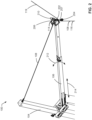
FIG. 1 depicts an unmanned aerial vehicle (UAV) recovery system in accordance with teachings of this disclosure. -
FIG. 2 is a detailed view of a portion of the example UAV recovery system ofFIG. 1 . -
FIG. 3 is a detailed view of an example loop that can be implemented in examples disclosed herein. -
FIG. 4 is a flowchart representative of an example method to implement the example UAV recovery system ofFIG. 1 . - The figures are not to scale. Instead, the thickness of the layers or regions may be enlarged in the drawings. In general, the same reference numbers will be used throughout the drawing(s) and accompanying written description to refer to the same or like parts. As used herein, unless otherwise stated, the term "above" describes the relationship of two parts relative to Earth. A first part is above a second part, if the second part has at least one part between Earth and the first part. Likewise, as used herein, a first part is "below" a second part when the first part is closer to the Earth than the second part. As noted above, a first part can be above or below a second part with one or more of: other parts therebetween, without other parts therebetween, with the first and second parts touching, or without the first and second parts being in direct contact with one another. As used in this patent, stating that any part is in any way on (e.g., positioned on, located on, disposed on, or formed on, etc.) another part, indicates that the referenced part is either in contact with the other part, or that the referenced part is above the other part with one or more intermediate part(s) located therebetween. As used herein, connection references (e.g., attached, coupled, connected, and joined) may include intermediate members between the elements referenced by the connection reference and/or relative movement between those elements unless otherwise indicated. As such, connection references do not necessarily infer that two elements are directly connected and/or in fixed relation to each other. As used herein, stating that any part is in "contact" with another part is defined to mean that there is no intermediate part between the two parts.
- Unless specifically stated otherwise, descriptors such as "first," "second," "third," etc. are used herein without imputing or otherwise indicating any meaning of priority, physical order, arrangement in a list, and/or ordering in any way, but are merely used as labels and/or arbitrary names to distinguish elements for ease of understanding the disclosed examples. In some examples, the descriptor "first" may be used to refer to an element in the detailed description, while the same element may be referred to in a claim with a different descriptor such as "second" or "third." In such instances, it should be understood that such descriptors are used merely for identifying those elements distinctly that might, for example, otherwise share a same name. As used herein, "approximately" and "about" refer to dimensions that may not be exact due to manufacturing tolerances and/or other real world imperfections.
- Methods and apparatus to recover unmanned aerial vehicles (UAVs) with kites are disclosed. Some UAVs are recovered by recovery systems, which employ a recovery tether line that is suspended vertically. In particular, a UAV contacts and/or impacts the tether line and, as a result, the UAV is decelerated and/or stopped from flight, thereby enabling recovery of the UAV without need for a runway. In some known implementations, a parachute or support beam is used to suspend the tether line for recovery of the UAV.
- Examples disclosed herein enable highly controlled and cost-effective recovery of an aircraft (e.g., a UAV) via a stationary platform or a moving vehicle or vessel (e.g., a ship, etc.). Examples disclosed herein enable aircraft to be recovered without a significant amount of force and/or stress imparted to the aircraft. As a result, examples disclosed herein can enable aircraft that do not require significant structural components that can be costly and have a significant amount of weight.
- Examples disclosed herein include a kite that supports a tether line. The tether line extends between a mast and a base. Further, the tether line is guided by boom that extends from the mast. When an aircraft is being recovered, the aircraft is brought into contact with a portion of the tether line that extends between an end of the boom (e.g., a distal end of the boom) and the base. The aircraft is decelerated by the tether line causing movement of the kite and, thus, dissipating kinetic energy of the aircraft. As a result, the aircraft encounters reduced impact and deceleration forces in contrast to known recovery systems. According to some examples disclosed herein, the portion of the tether line is positioned on a first side of the boom while the kite is positioned on a second side of the boom opposite the first side (e.g., the portion of the tether line is positioned below the boom while the kite is positioned above the boom).
- In some examples, the tether line is guided through a fixed point (e.g., a fixed point loop or ring) of the aforementioned boom. In some examples, the tether line is coupled to the kite via an alpine butterfly knot of the tether line (e.g., positioned on the tether line). In some examples, a brake is implemented to decelerate the tether line and, in turn, the aircraft subsequent to the aircraft impacting the tether line. Additionally or alternatively, a spring is implemented to dampen movement of the tether line, the boom and/or the kite. In some examples, the boom is telescoping and/or an angle of the boom can be adjusted to vary an amount of deceleration imparted to the aircraft during recovery thereof. In some examples, kites coupled to the tether line are interchangeable and/or selectable for different kite configurations, aircraft configurations and/or kite recovery requirements.
-
FIG. 1 depicts an unmanned aerial vehicle (UAV)recovery system 100 in accordance with teachings of this disclosure. TheUAV recovery system 100 of the illustrated example is implemented to recover anaircraft 101 and includes abase 102, amast 104, aboom 106, and atether line 108. In this example, theboom 106 includes a first end (e.g., a proximal end) 112 at themast 104 and a second end (e.g., a distal end) 114 of theboom 106 that is opposite thefirst end 112. Thetether line 108 of the illustrated example extends from themast 104 to thebase 102, and is guided by theboom 106. Further, afirst portion 116 of thetether line 108 extends from thebase 102 and/or the ground associated with the base 102 to thesecond end 114 for contact with theUAV 101 while asecond portion 118 of thetether line 108 extends between thesecond end 114 and themast 104 to constrain/guide thetether line 108. In the illustrated example, akite 120 is shown with at least onesupport line 119 coupled to thetether line 108 at or proximate thesecond end 114. Further, theexample kite 120 is depicted deployed above themast 104 as well as theboom 106. As will be discussed in greater detail below in connection withFIG. 2 , in this example, thekite 120 is coupled to thetether line 108 to dissipate energy during impact of theUAV 101 with thetether line 108. In other examples, thetether line 108 extends above theboom 106 to the kite 120 (e.g., thetether line 108 extends to thekite 120, returns from thekite 120, extends across theboom 106 and back to the mast 104). - The
example UAV 101 includes afuselage 121,wings 122 each of which includes adistal capture portion 123, and apropulsion system 124. In this example, thedistal capture portion 123 extends from at least one of the correspondingwings 122 generally along a direction of movement of theUAV 101. However, any appropriate type of capture or recovery mechanism can, instead, be implemented on any other portion and/or component (e.g., the fuselage 121) of theUAV 101. Further any other appropriate type of propulsion of theUAV 101 can be implemented. - To recover and/or capture the
UAV 101 as theUAV 101 moves along aflight path 126, one of thedistal capture portions 123 is brought into contact with thefirst portion 116 of thetether line 108 extending between theboom 106 and thebase 102. TheUAV 101 contacting thetether line 108 causes thekite 120 to displace, thereby decelerating theUAV 101 in a highly effective and controlled manner. As a result, theUAV 101 is brought to a rest or stop with minimal force and/or stress and remains attached to thetether line 108. In this example, thefirst portion 116 of thetether line 108 is suspended by the boom 106 (e.g., substantially vertically in the air, within 5 degrees from vertical) above the base 102 but is also operatively coupled to thekite 120 so that thekite 120 can facilitate controlled deceleration of theUAV 101. -
FIG. 2 is a detailed view of a portion of the exampleUAV recovery system 100 ofFIG. 1 . As can be seen in the illustrated example ofFIG. 2 , theboom 106 is depicted extending from themast 104. As mentioned above in connection withFIG. 1 , thetether line 108 is attached to thekite 120 ofFIG. 1 . In particular, thesupport line 119 of thekite 120 is coupled to thetether line 108 at amount 202, which can operate as a coupling point (e.g., a fixed point) between thetether line 108 and thesupport line 119. Themount 202 can be positioned on thetether line 108 or the boom 106 (e.g., thesecond end 114 of the boom 106). In other examples, thetether line 108 extends above theboom 106 to contact thekite 120. In some such examples, thesupport line 119 is integral with thetether line 108. In this example, a pulley (e.g., a one-way pulley, a braking pulley, etc.) 204 and guides 206 direct and/or guide thetether line 108 from the base 102 shown inFIG. 1 to theboom 106 and, in turn, themast 104. As a result, the guided movement of thetether line 108 enables kinetic energy from theUAV 101 to be effectively dissipated as theUAV 101 is being decelerated during recovery thereof. - In the illustrated example, to couple movement of the
tether line 108 with displacement and/or movement of thekite 120 when theUAV 101 is brought into contact with theportion 116 of thetether line 108, thesupport line 119 is coupled to thetether line 108 via themount 202, which operates as a fixed point of thetether line 108 in this example. Themount 202 moves and/or displaces along with thetether line 108 during deceleration of theUAV 101, thereby causing thekite 120 to move (e.g., causing a sudden or jerking motion of the kite 120). Theexample mount 202 can be implemented as or generally shaped as a loop or ring (e.g., a ring, an annular ring, a loop of thetether line 108, etc.) to couple thesupport line 119 to thetether line 108. As will be discussed in greater detail below in connection withFIG. 3 , thesupport line 119 can be attached to a loop or ring defined by thetether line 108. In some examples, themount 202 is defined as a tied knot of thetether line 108. Additionally or alternatively, thepulley 204 and theguides 206 can be adjusted to vary deceleration of theUAV 101. - In some examples, a
spring 207 is implemented to dampen motion of thetether line 108 and/or thekite 120. In some examples, abrake 210 is implemented to control movement of thetether line 108, thepulley 204 and/or thekite 120. For example, thebrake 210 can be operatively coupled to thepulley 204 to vary rotational movement of thepulley 204 and, in turn, motion of thetether line 108 and thekite 120 can be accurately controlled. Thebrake 210 can be electronically-controlled, force-controlled (e.g., via a force-reaction device) or manually-controlled. In some examples, as generally indicated by adouble arrow 212, an angle of theboom 106 relative to themast 104 can be adjusted to vary a degree to which thekite 120 decelerates theUAV 101 shown inFIG. 1 . Additionally or alternatively, a height at which thekite 120 is positioned is changed to vary the degree to which thekite 120 decelerates theUAV 101. In some examples, as generally indicated by adouble arrow 214, theboom 106 is telescoping and its longitudinal length can be varied to change a degree to which thekite 120 decelerates theUAV 101. - In some other examples, different kites are interchanged and/or selected based on a type or configuration of aircraft being recovered and/or environmental conditions (e.g., wind conditions, kite hovering height limitations, etc.). In other words, different kites can be coupled to the
tether line 108 and/or themount 202 based on different aircraft configuration types and/or environmental conditions. In some such examples, utilization of theaforementioned mount 202 facilitates interchangeability between the different kites by enabling relatively easy and quick installation of the kites. -
FIG. 3 is a detailed view of anexample loop 300 that can be implemented in examples disclosed herein. In particular, theexample loop 300 can be implemented onto thetether line 108 and/or themount 202. Theloop 300 of the illustrated example is positioned on or proximate thesecond end 114 of theboom 106 shown inFIG. 1 . In this particular example, theloop 300 is implemented as an alpine butterfly knot of thetether line 108. However, any other appropriate knot (e.g., a figure 8 knot, a noose knot, a square knot, an overhand knot, a slip knot, etc.) or other looped/loop-like structure can be implemented instead. -
FIG. 4 is a flowchart representative of anexample method 400 to implement the exampleUAV recovery system 100 ofFIG. 1 . In this example, an aircraft (e.g., the UAV 101) is going to be recovered by thetether line 108 and thekite 120 is to decelerate theUAV 101 during recovery of theUAV 101. - At
block 402, thekite 120 is launched and/or deployed. In this example, thekite 120 is coupled to the tether line 108 (e.g., at the mount 202), thereby coupling motion between thekite 120 and thetether line 108. In other words, movement of at least a portion of thetether line 108 causes movement of thekite 120. In some examples, a height to which thekite 120 is launched is varied based on a desired degree of deceleration of the aircraft (e.g., a greater height corresponds to a greater degree of deceleration of the aircraft). - At
block 404, thetether line 108 is suspended by thekite 120 operatively coupled thereto. In the illustrated example, theportion 116 of thetether line 108 is suspended (e.g., held in tension) between theboom 106 and thebase 102 and/or the ground for impact with the aircraft. In some examples, thetether line 108 is routed through a fixed point of at least one of theboom 106 and/or thetether line 108. - At
block 405, in some examples, a height at which thekite 120 is deployed is changed and/or adjusted. In some such examples, the height may be adjusted on flight data of the aircraft and/or changing conditions (e.g., changing wind conditions, changing weather conditions, etc.). - At
block 406, in some examples, theboom 106 is adjusted. In some examples, an angle of the boom 106 (e.g., an angle of theboom 106 from the ground) is adjusted to vary a degree of deceleration of the aircraft. Additionally or alternatively, a longitudinal length of theboom 106 is adjusted (e.g., theboom 106 is telescoping). - At
block 407, the aircraft is brought into contact with thetether line 108. In this example, the aircraft is flown along a flight path that results in a distal portion of a wing of the aircraft contacting thetether line 108. In turn, the aircraft is decelerated to a stop as thetether line 108 moves thekite 120. In other words, movement ofkite 120 dissipates kinetic energy of the aircraft. In some examples, the aircraft is coupled (e.g., releasably coupled) to thetether line 108 in response to impacting the tether line 108 (e.g., the aircraft hangs from thetether line 108 after impacting the tether line 108). - At
block 408, in some examples, thebrake 210 is operated. In particular, thebrake 210 can be operated to slow down and/or prevent movement of thetether line 108 as the aircraft is being recovered (i.e., after the aircraft has been brought to a rest via thetether line 108 and the kite 120). Additionally or alternatively, thebrake 210 is implemented to prevent, reduce and/or dampen movement of thetether line 108 as the aircraft is being decelerated (e.g., to prevent excess movement of thetether line 108 prior to the aircraft being recovered). Theexample brake 210 can be implemented to reduce and/or slow down movement of thepulley 204. According to some examples, thespring 207 is implemented (e.g., in-line with or operatively coupled to thetether line 108, at themount 202, between thesupport line 119 and thetether line 108, etc.) to dampen motion of thetether line 108 and/or thekite 120 during recovery of the aircraft. - At
block 410, the aircraft is drawn in toward thebase 102. In some examples, thetether line 108 is displaced and/moved (e.g., moved linearly, moved by a winch) so that the aircraft can be removed from thetether line 108. In some examples, an operator removes the aircraft from thetether line 108 as the aircraft is suspended by thetether line 108. - At
block 411, in some examples, thekite 120 is replaced with another kite, which can correspond to a different type or configuration of aircraft being recovered, etc. In some such examples, the replacement kite is coupled to thetether line 108 at themount 202. - At
block 412, it is determined whether to repeat the process. If the process is to be repeated (block 412), control of the process returns to block 402. Otherwise, the process ends. This determination may be based on whether additional aircraft are to be recovered. - From the foregoing, it will be appreciated that example methods, apparatus and articles of manufacture have been disclosed that enable highly controlled and cost-effective recovery of aircraft. Examples disclosed herein can also reduce forces and/or stresses imparted to aircraft during recovery thereof. Examples disclosed herein also enable aircraft that have a relatively light weight and low cost because they do not necessitate significant structural reinforcements and components for landing, etc.
- "Including" and "comprising" (and all forms and tenses thereof) are used herein to be open ended terms. Thus, whenever a claim employs any form of "include" or "comprise" (e.g., comprises, includes, comprising, including, having, etc.) as a preamble or within a claim recitation of any kind, it is to be understood that additional elements, terms, etc. may be present without falling outside the scope of the corresponding claim or recitation. As used herein, when the phrase "at least" is used as the transition term in, for example, a preamble of a claim, it is open-ended in the same manner as the term "comprising" and "including" are open ended. The term "and/or" when used, for example, in a form such as A, B, and/or C refers to any combination or subset of A, B, C such as (1) A alone, (2) B alone, (3) C alone, (4) A with B, (5) A with C, (6) B with C, and (7) A with B and with C. As used herein in the context of describing structures, components, items, objects and/or things, the phrase "at least one of A and B" is intended to refer to implementations including any of (1) at least one A, (2) at least one B, and (3) at least one A and at least one B. Similarly, as used herein in the context of describing structures, components, items, objects and/or things, the phrase "at least one of A or B" is intended to refer to implementations including any of (1) at least one A, (2) at least one B, and (3) at least one A and at least one B. As used herein in the context of describing the performance or execution of processes, instructions, actions, activities and/or steps, the phrase "at least one of A and B" is intended to refer to implementations including any of (1) at least one A, (2) at least one B, and (3) at least one A and at least one B. Similarly, as used herein in the context of describing the performance or execution of processes, instructions, actions, activities and/or steps, the phrase "at least one of A or B" is intended to refer to implementations including any of (1) at least one A, (2) at least one B, and (3) at least one A and at least one B.
- As used herein, singular references (e.g., "a", "an", "first", "second", etc.) do not exclude a plurality. The term "a" or "an" entity, as used herein, refers to one or more of that entity. The terms "a" (or "an"), "one or more", and "at least one" can be used interchangeably herein. Furthermore, although individually listed, a plurality of means, elements or method actions may be implemented by, e.g., a single unit or processor. Additionally, although individual features may be included in different examples or claims, these may possibly be combined, and the inclusion in different examples or claims does not imply that a combination of features is not feasible and/or advantageous.
- Although certain example methods, apparatus and articles of manufacture have been disclosed herein, the scope of coverage of this patent is not limited thereto. On the contrary, this patent covers all methods, apparatus and articles of manufacture falling within the scope of the claims of this patent.
- The following claims are hereby incorporated into this Detailed Description by this reference, with each claim standing on its own as a separate embodiment of the present disclosure.
Claims (15)
- An apparatus (100) to recover an aircraft (101), the apparatus (100) comprising:a base (102);a mast (104) extending from the base (102);a boom (106) extending from the mast (104) at a first end (112) of the boom (106) to a second end (114) of the boom opposite the first end (112);a tether line (108) extending between the mast (104) and the base (102), said tether line being guided by the boom (106), a portion (116) of the tether line (108) extending between the second end (114) of the boom (106) and the base (102);a kite (120) coupled to the tether line (108) via a support line (119); anda mount (202) configured to operatively couple the support line (119) to the tether line (108), the kite (120) being configured to support the tether line (108) as the aircraft (101) contacts the portion (116) of the tether line (108) extending between the second end (114) of the boom (106) and the base (102) for recovery of the aircraft (101),wherein the mount (202) is configured to move and/or displace along with the tether line (108) during deceleration of the aircraft (101), thereby causing the kite (120) to move.
- The apparatus (100) as defined in claim 1, wherein the mount (202) defines a fixed point of the boom (106).
- The apparatus (100) as defined in any of claims 1 to 2, wherein the mount (202) defines a fixed point of the tether line (108).
- The apparatus (100) as defined in any of claims 1 to 3, wherein the mount (202) includes a loop (300).
- The apparatus (100) as defined in claim 4, wherein the loop (300) includes an alpine butterfly knot.
- The apparatus (100) as defined in any of claims 1 to 5, further including a brake (210) operatively coupled to the tether line (108).
- The apparatus (100) as defined in any of claims 1 to 6, further including a spring (207) operatively coupled to the tether line (108).
- The apparatus (100) as defined in any of claims 1 to 7, wherein the aircraft (101) is to contact the tether line (108) on a first side of the boom (106), and wherein the kite (120) is to be positioned on a second side of the boom (106) opposite the first side.
- The apparatus (100) as defined in any of claims 1 to 8, wherein the portion (116) of the tether line (108) extends generally vertical with respect to the ground.
- A method (400) to recover an aircraft (101), the method (400) comprising:launching a kite (120) configured to support a tether line (108), the tether line (108) extending from a mast (104) to a base (102), the tether line (108) being guided by a boom (106), wherein the boom (106) extends from a first end (112) to a second end (114) opposite the first end (112), the first end (112) being positioned at the mast (104):contacting the aircraft (101) with a portion (116) of the tether line (108) that extends from the second end (114) of the boom (106) to the base (102) to decelerate the aircraft (101); andretrieving the aircraft (101) from the tether line (108),wherein the kite (120) is coupled to the tether line (108) by a support line (119) via a mount (202), andwherein contacting the aircraft (101) with a portion (116) of the tether line (108) includes movement/displacement of the mount (202) along with tether line (108) causing the kite (120) to move.
- The method as defined in claim 10, wherein contacting the aircraft (101) with the portion (116) of the tether line (108) includes coupling the aircraft (101) to the tether line (108).
- The method as defined in any of claims 10 to 11, further including changing a distance from the second end (114) of the boom (106) to the kite (120) to vary an amount of deceleration of the aircraft (101).
- The method as defined in any of claims 10 to 12, further including changing an angle of the boom (106) relative to the ground to vary an amount of deceleration of the aircraft (101).
- The method as defined in any of claims 10 to 13, further including routing the tether line (108) through a fixed point at the second end (114) of the boom (106).
- The method as defined in any of claims 10 to 14, wherein the kite (120) is a first kite, and further including replacing the first kite with a second kite different from the first kite based on at least one of an aircraft (101) configuration or environmental conditions.
Applications Claiming Priority (1)
| Application Number | Priority Date | Filing Date | Title |
|---|---|---|---|
| US17/365,560 US11772815B2 (en) | 2021-07-01 | 2021-07-01 | Methods and apparatus to recover unmanned aerial vehicles with kites |
Publications (2)
| Publication Number | Publication Date |
|---|---|
| EP4112458A1 EP4112458A1 (en) | 2023-01-04 |
| EP4112458B1 true EP4112458B1 (en) | 2024-10-16 |
Family
ID=82492895
Family Applications (1)
| Application Number | Title | Priority Date | Filing Date |
|---|---|---|---|
| EP22182504.5A Active EP4112458B1 (en) | 2021-07-01 | 2022-07-01 | Methods and apparatus to recover unmanned aerial vehicles with kites |
Country Status (3)
| Country | Link |
|---|---|
| US (1) | US11772815B2 (en) |
| EP (1) | EP4112458B1 (en) |
| CN (1) | CN115556956A (en) |
Families Citing this family (1)
| Publication number | Priority date | Publication date | Assignee | Title |
|---|---|---|---|---|
| CN118850326B (en) * | 2024-09-25 | 2024-11-26 | 湖南科技学院 | Logistics unmanned aerial vehicle |
Family Cites Families (16)
| Publication number | Priority date | Publication date | Assignee | Title |
|---|---|---|---|---|
| US4753400A (en) * | 1987-02-13 | 1988-06-28 | Pioneer Systems, Incorporated | Shipboard air vehicle retrieval apparatus |
| US6264140B1 (en) * | 1999-06-08 | 2001-07-24 | Mcgeer Brian T. | Method for retrieving a fixed-wing aircraft without a runway |
| US6874729B1 (en) * | 1999-07-23 | 2005-04-05 | Advanced Aerospace Technologies, Inc. | Launch and recovery system for unmanned aerial vehicles |
| US7114680B2 (en) * | 2003-01-17 | 2006-10-03 | The Insitu Group, Inc. | Methods and apparatuses for launching and capturing unmanned aircraft, including a combined launch and recovery system |
| AU2015248219A1 (en) * | 2014-01-14 | 2016-07-28 | Advanced Product Development, Llc | Asymmetric aircraft and their launch and recovery systems from small ships |
| JP2017517439A (en) * | 2014-06-11 | 2017-06-29 | エンジニアード・アレスティング・システムズ・コーポレーションEngineered Arresting Systems Corporation | Unmanned aerial vehicle collection system |
| WO2016085404A1 (en) * | 2014-11-27 | 2016-06-02 | Singapore Technologies Aerospace Ltd | Apparatus and method for launch and recovery of an unmanned aerial vehicle |
| CN205971887U (en) * | 2016-07-14 | 2017-02-22 | 西安思坦测控技术有限公司 | Unmanned aerial vehicle recovery system |
| US11414187B2 (en) * | 2017-09-06 | 2022-08-16 | Hood Technology Corporation | Parasail-assisted systems and methods for launching and retrieving a fixed-wing aircraft into and from free flight |
| US11066185B2 (en) * | 2018-05-04 | 2021-07-20 | Insitu, Inc. | Launch and/or recovery for unmanned aircraft and/or other payloads, including via parachute-assist, and associated systems and methods |
| US11008101B2 (en) * | 2018-10-26 | 2021-05-18 | Ford Global Technologies, Llc | Systems, methods, and devices for package delivery using unmanned aerial vehicles |
| US11235892B2 (en) * | 2019-05-22 | 2022-02-01 | Hood Technology Corporation | Aircraft retrieval system and method |
| CN210102017U (en) * | 2019-06-11 | 2020-02-21 | 三一汽车制造有限公司 | Unmanned aerial vehicle recovery unit |
| US11542037B2 (en) | 2019-12-09 | 2023-01-03 | Insitu, Inc. | Methods and apparatus to deploy unmanned aerial vehicles (UAVs) by kites |
| US11745897B2 (en) * | 2019-12-09 | 2023-09-05 | Insitu, Inc. | Methods and apparatus to recover unmanned aerial vehicles (UAVs) with kites |
| CN112278312A (en) * | 2020-10-29 | 2021-01-29 | 河北淳博航空科技有限公司 | Recovery device for marine unmanned aerial vehicle |
-
2021
- 2021-07-01 US US17/365,560 patent/US11772815B2/en active Active
-
2022
- 2022-07-01 EP EP22182504.5A patent/EP4112458B1/en active Active
- 2022-07-01 CN CN202210773687.7A patent/CN115556956A/en active Pending
Also Published As
| Publication number | Publication date |
|---|---|
| CN115556956A (en) | 2023-01-03 |
| EP4112458A1 (en) | 2023-01-04 |
| US11772815B2 (en) | 2023-10-03 |
| US20230002075A1 (en) | 2023-01-05 |
Similar Documents
| Publication | Publication Date | Title |
|---|---|---|
| US7143974B2 (en) | Methods and apparatuses for launching airborne devices along flexible elongated members | |
| EP2421757B1 (en) | Systems and methods for recovering and controlling post-recovery motion of unmanned aircraft | |
| US6264140B1 (en) | Method for retrieving a fixed-wing aircraft without a runway | |
| EP1233905B1 (en) | Launch and recovery system for unmanned aerial vehicles | |
| AU2007347147B2 (en) | Method and apparatus for retrieving a hovering aircraft | |
| US6874729B1 (en) | Launch and recovery system for unmanned aerial vehicles | |
| EP3268277B1 (en) | Uav capture system | |
| US20020100838A1 (en) | Method and apparatus for retrieving a flying object | |
| US20200283145A1 (en) | Unmanned aerial vehicle (uav) recovery | |
| US20160221689A1 (en) | Line Intersect Vehicle Launch and Recovery | |
| US11492141B2 (en) | Systems and methods for capturing and recovering unmanned aircraft | |
| EP4112458A1 (en) | Methods and apparatus to recover unmanned aerial vehicles with kites | |
| EP4112457A1 (en) | Methods and apparatus to recover unmanned aerial vehicles with kites | |
| EP4079642B1 (en) | Rotatable masts to recover aircraft with kites | |
| AU2015275315B2 (en) | Systems and methods for recovering and controlling post-recovery motion of unmanned aircraft |
Legal Events
| Date | Code | Title | Description |
|---|---|---|---|
| PUAI | Public reference made under article 153(3) epc to a published international application that has entered the european phase |
Free format text: ORIGINAL CODE: 0009012 |
|
| STAA | Information on the status of an ep patent application or granted ep patent |
Free format text: STATUS: THE APPLICATION HAS BEEN PUBLISHED |
|
| AK | Designated contracting states |
Kind code of ref document: A1 Designated state(s): AL AT BE BG CH CY CZ DE DK EE ES FI FR GB GR HR HU IE IS IT LI LT LU LV MC MK MT NL NO PL PT RO RS SE SI SK SM TR |
|
| STAA | Information on the status of an ep patent application or granted ep patent |
Free format text: STATUS: REQUEST FOR EXAMINATION WAS MADE |
|
| 17P | Request for examination filed |
Effective date: 20230531 |
|
| RBV | Designated contracting states (corrected) |
Designated state(s): AL AT BE BG CH CY CZ DE DK EE ES FI FR GB GR HR HU IE IS IT LI LT LU LV MC MK MT NL NO PL PT RO RS SE SI SK SM TR |
|
| GRAP | Despatch of communication of intention to grant a patent |
Free format text: ORIGINAL CODE: EPIDOSNIGR1 |
|
| STAA | Information on the status of an ep patent application or granted ep patent |
Free format text: STATUS: GRANT OF PATENT IS INTENDED |
|
| INTG | Intention to grant announced |
Effective date: 20240510 |
|
| GRAS | Grant fee paid |
Free format text: ORIGINAL CODE: EPIDOSNIGR3 |
|
| GRAA | (expected) grant |
Free format text: ORIGINAL CODE: 0009210 |
|
| STAA | Information on the status of an ep patent application or granted ep patent |
Free format text: STATUS: THE PATENT HAS BEEN GRANTED |
|
| AK | Designated contracting states |
Kind code of ref document: B1 Designated state(s): AL AT BE BG CH CY CZ DE DK EE ES FI FR GB GR HR HU IE IS IT LI LT LU LV MC MK MT NL NO PL PT RO RS SE SI SK SM TR |
|
| REG | Reference to a national code |
Ref country code: GB Ref legal event code: FG4D |
|
| REG | Reference to a national code |
Ref country code: CH Ref legal event code: EP |
|
| REG | Reference to a national code |
Ref country code: IE Ref legal event code: FG4D |
|
| REG | Reference to a national code |
Ref country code: DE Ref legal event code: R096 Ref document number: 602022006811 Country of ref document: DE |
|
| P01 | Opt-out of the competence of the unified patent court (upc) registered |
Free format text: CASE NUMBER: APP_54854/2024 Effective date: 20241004 |
|
| REG | Reference to a national code |
Ref country code: LT Ref legal event code: MG9D |
|
| REG | Reference to a national code |
Ref country code: NL Ref legal event code: MP Effective date: 20241016 |
|
| REG | Reference to a national code |
Ref country code: AT Ref legal event code: MK05 Ref document number: 1732748 Country of ref document: AT Kind code of ref document: T Effective date: 20241016 |
|
| PG25 | Lapsed in a contracting state [announced via postgrant information from national office to epo] |
Ref country code: NL Free format text: LAPSE BECAUSE OF FAILURE TO SUBMIT A TRANSLATION OF THE DESCRIPTION OR TO PAY THE FEE WITHIN THE PRESCRIBED TIME-LIMIT Effective date: 20241016 |
|
| PG25 | Lapsed in a contracting state [announced via postgrant information from national office to epo] |
Ref country code: NL Free format text: LAPSE BECAUSE OF FAILURE TO SUBMIT A TRANSLATION OF THE DESCRIPTION OR TO PAY THE FEE WITHIN THE PRESCRIBED TIME-LIMIT Effective date: 20241016 |
|
| PG25 | Lapsed in a contracting state [announced via postgrant information from national office to epo] |
Ref country code: HR Free format text: LAPSE BECAUSE OF FAILURE TO SUBMIT A TRANSLATION OF THE DESCRIPTION OR TO PAY THE FEE WITHIN THE PRESCRIBED TIME-LIMIT Effective date: 20241016 Ref country code: PT Free format text: LAPSE BECAUSE OF FAILURE TO SUBMIT A TRANSLATION OF THE DESCRIPTION OR TO PAY THE FEE WITHIN THE PRESCRIBED TIME-LIMIT Effective date: 20250217 Ref country code: IS Free format text: LAPSE BECAUSE OF FAILURE TO SUBMIT A TRANSLATION OF THE DESCRIPTION OR TO PAY THE FEE WITHIN THE PRESCRIBED TIME-LIMIT Effective date: 20250216 |
|
| PG25 | Lapsed in a contracting state [announced via postgrant information from national office to epo] |
Ref country code: FI Free format text: LAPSE BECAUSE OF FAILURE TO SUBMIT A TRANSLATION OF THE DESCRIPTION OR TO PAY THE FEE WITHIN THE PRESCRIBED TIME-LIMIT Effective date: 20241016 |
|
| PG25 | Lapsed in a contracting state [announced via postgrant information from national office to epo] |
Ref country code: BG Free format text: LAPSE BECAUSE OF FAILURE TO SUBMIT A TRANSLATION OF THE DESCRIPTION OR TO PAY THE FEE WITHIN THE PRESCRIBED TIME-LIMIT Effective date: 20241016 |
|
| PG25 | Lapsed in a contracting state [announced via postgrant information from national office to epo] |
Ref country code: ES Free format text: LAPSE BECAUSE OF FAILURE TO SUBMIT A TRANSLATION OF THE DESCRIPTION OR TO PAY THE FEE WITHIN THE PRESCRIBED TIME-LIMIT Effective date: 20241016 |
|
| PG25 | Lapsed in a contracting state [announced via postgrant information from national office to epo] |
Ref country code: NO Free format text: LAPSE BECAUSE OF FAILURE TO SUBMIT A TRANSLATION OF THE DESCRIPTION OR TO PAY THE FEE WITHIN THE PRESCRIBED TIME-LIMIT Effective date: 20250116 |
|
| PG25 | Lapsed in a contracting state [announced via postgrant information from national office to epo] |
Ref country code: LV Free format text: LAPSE BECAUSE OF FAILURE TO SUBMIT A TRANSLATION OF THE DESCRIPTION OR TO PAY THE FEE WITHIN THE PRESCRIBED TIME-LIMIT Effective date: 20241016 Ref country code: GR Free format text: LAPSE BECAUSE OF FAILURE TO SUBMIT A TRANSLATION OF THE DESCRIPTION OR TO PAY THE FEE WITHIN THE PRESCRIBED TIME-LIMIT Effective date: 20250117 Ref country code: AT Free format text: LAPSE BECAUSE OF FAILURE TO SUBMIT A TRANSLATION OF THE DESCRIPTION OR TO PAY THE FEE WITHIN THE PRESCRIBED TIME-LIMIT Effective date: 20241016 |
|
| PG25 | Lapsed in a contracting state [announced via postgrant information from national office to epo] |
Ref country code: PL Free format text: LAPSE BECAUSE OF FAILURE TO SUBMIT A TRANSLATION OF THE DESCRIPTION OR TO PAY THE FEE WITHIN THE PRESCRIBED TIME-LIMIT Effective date: 20241016 |
|
| PG25 | Lapsed in a contracting state [announced via postgrant information from national office to epo] |
Ref country code: RS Free format text: LAPSE BECAUSE OF FAILURE TO SUBMIT A TRANSLATION OF THE DESCRIPTION OR TO PAY THE FEE WITHIN THE PRESCRIBED TIME-LIMIT Effective date: 20250116 |
|
| PG25 | Lapsed in a contracting state [announced via postgrant information from national office to epo] |
Ref country code: SM Free format text: LAPSE BECAUSE OF FAILURE TO SUBMIT A TRANSLATION OF THE DESCRIPTION OR TO PAY THE FEE WITHIN THE PRESCRIBED TIME-LIMIT Effective date: 20241016 |
|
| PG25 | Lapsed in a contracting state [announced via postgrant information from national office to epo] |
Ref country code: DK Free format text: LAPSE BECAUSE OF FAILURE TO SUBMIT A TRANSLATION OF THE DESCRIPTION OR TO PAY THE FEE WITHIN THE PRESCRIBED TIME-LIMIT Effective date: 20241016 |
|
| REG | Reference to a national code |
Ref country code: DE Ref legal event code: R097 Ref document number: 602022006811 Country of ref document: DE |
|
| PG25 | Lapsed in a contracting state [announced via postgrant information from national office to epo] |
Ref country code: EE Free format text: LAPSE BECAUSE OF FAILURE TO SUBMIT A TRANSLATION OF THE DESCRIPTION OR TO PAY THE FEE WITHIN THE PRESCRIBED TIME-LIMIT Effective date: 20241016 |
|
| PG25 | Lapsed in a contracting state [announced via postgrant information from national office to epo] |
Ref country code: RO Free format text: LAPSE BECAUSE OF FAILURE TO SUBMIT A TRANSLATION OF THE DESCRIPTION OR TO PAY THE FEE WITHIN THE PRESCRIBED TIME-LIMIT Effective date: 20241016 |
|
| PG25 | Lapsed in a contracting state [announced via postgrant information from national office to epo] |
Ref country code: SK Free format text: LAPSE BECAUSE OF FAILURE TO SUBMIT A TRANSLATION OF THE DESCRIPTION OR TO PAY THE FEE WITHIN THE PRESCRIBED TIME-LIMIT Effective date: 20241016 |
|
| PG25 | Lapsed in a contracting state [announced via postgrant information from national office to epo] |
Ref country code: CZ Free format text: LAPSE BECAUSE OF FAILURE TO SUBMIT A TRANSLATION OF THE DESCRIPTION OR TO PAY THE FEE WITHIN THE PRESCRIBED TIME-LIMIT Effective date: 20241016 |
|
| PG25 | Lapsed in a contracting state [announced via postgrant information from national office to epo] |
Ref country code: IT Free format text: LAPSE BECAUSE OF FAILURE TO SUBMIT A TRANSLATION OF THE DESCRIPTION OR TO PAY THE FEE WITHIN THE PRESCRIBED TIME-LIMIT Effective date: 20241016 |
|
| PLBE | No opposition filed within time limit |
Free format text: ORIGINAL CODE: 0009261 |
|
| STAA | Information on the status of an ep patent application or granted ep patent |
Free format text: STATUS: NO OPPOSITION FILED WITHIN TIME LIMIT |
|
| PG25 | Lapsed in a contracting state [announced via postgrant information from national office to epo] |
Ref country code: SE Free format text: LAPSE BECAUSE OF FAILURE TO SUBMIT A TRANSLATION OF THE DESCRIPTION OR TO PAY THE FEE WITHIN THE PRESCRIBED TIME-LIMIT Effective date: 20241016 |
|
| 26N | No opposition filed |
Effective date: 20250717 |
|
| PGFP | Annual fee paid to national office [announced via postgrant information from national office to epo] |
Ref country code: DE Payment date: 20250729 Year of fee payment: 4 |
|
| PGFP | Annual fee paid to national office [announced via postgrant information from national office to epo] |
Ref country code: FR Payment date: 20250725 Year of fee payment: 4 |
|
| REG | Reference to a national code |
Ref country code: CH Ref legal event code: H13 Free format text: ST27 STATUS EVENT CODE: U-0-0-H10-H13 (AS PROVIDED BY THE NATIONAL OFFICE) Effective date: 20260224 |
|
| PG25 | Lapsed in a contracting state [announced via postgrant information from national office to epo] |
Ref country code: LU Free format text: LAPSE BECAUSE OF NON-PAYMENT OF DUE FEES Effective date: 20250701 |
|
| REG | Reference to a national code |
Ref country code: BE Ref legal event code: MM Effective date: 20250731 |
|
| PG25 | Lapsed in a contracting state [announced via postgrant information from national office to epo] |
Ref country code: BE Free format text: LAPSE BECAUSE OF NON-PAYMENT OF DUE FEES Effective date: 20250731 |
|
| PG25 | Lapsed in a contracting state [announced via postgrant information from national office to epo] |
Ref country code: CH Free format text: LAPSE BECAUSE OF NON-PAYMENT OF DUE FEES Effective date: 20250731 |
|
| PG25 | Lapsed in a contracting state [announced via postgrant information from national office to epo] |
Ref country code: LT Free format text: LAPSE BECAUSE OF FAILURE TO SUBMIT A TRANSLATION OF THE DESCRIPTION OR TO PAY THE FEE WITHIN THE PRESCRIBED TIME-LIMIT Effective date: 20241016 |
|
| PG25 | Lapsed in a contracting state [announced via postgrant information from national office to epo] |
Ref country code: IE Free format text: LAPSE BECAUSE OF NON-PAYMENT OF DUE FEES Effective date: 20250701 |
|
| PG25 | Lapsed in a contracting state [announced via postgrant information from national office to epo] |
Ref country code: MC Free format text: LAPSE BECAUSE OF FAILURE TO SUBMIT A TRANSLATION OF THE DESCRIPTION OR TO PAY THE FEE WITHIN THE PRESCRIBED TIME-LIMIT Effective date: 20241016 |
|
| PG25 | Lapsed in a contracting state [announced via postgrant information from national office to epo] |
Ref country code: CY Free format text: LAPSE BECAUSE OF FAILURE TO SUBMIT A TRANSLATION OF THE DESCRIPTION OR TO PAY THE FEE WITHIN THE PRESCRIBED TIME-LIMIT Effective date: 20241016 |