EP4112443A1 - Structural system for an aircraft for installation of equipment - Google Patents
Structural system for an aircraft for installation of equipment Download PDFInfo
- Publication number
- EP4112443A1 EP4112443A1 EP21182980.9A EP21182980A EP4112443A1 EP 4112443 A1 EP4112443 A1 EP 4112443A1 EP 21182980 A EP21182980 A EP 21182980A EP 4112443 A1 EP4112443 A1 EP 4112443A1
- Authority
- EP
- European Patent Office
- Prior art keywords
- bracket
- structural system
- equipment
- stiffening
- piece
- Prior art date
- Legal status (The legal status is an assumption and is not a legal conclusion. Google has not performed a legal analysis and makes no representation as to the accuracy of the status listed.)
- Granted
Links
Images


Classifications
-
- B—PERFORMING OPERATIONS; TRANSPORTING
- B64—AIRCRAFT; AVIATION; COSMONAUTICS
- B64C—AEROPLANES; HELICOPTERS
- B64C1/00—Fuselages; Constructional features common to fuselages, wings, stabilising surfaces or the like
- B64C1/06—Frames; Stringers; Longerons ; Fuselage sections
- B64C1/061—Frames
-
- B—PERFORMING OPERATIONS; TRANSPORTING
- B64—AIRCRAFT; AVIATION; COSMONAUTICS
- B64D—EQUIPMENT FOR FITTING IN OR TO AIRCRAFT; FLIGHT SUITS; PARACHUTES; ARRANGEMENT OR MOUNTING OF POWER PLANTS OR PROPULSION TRANSMISSIONS IN AIRCRAFT
- B64D11/00—Passenger or crew accommodation; Flight-deck installations not otherwise provided for
- B64D11/003—Stowage devices for passengers' personal luggage
Definitions
- the invention relates to a structural system for an aircraft and an aircraft having a structural system and at least one piece of equipment attachable to the structural system.
- circumferential stiffening frames as well as longitudinally arranged axial stiffening elements are provided to stiffen the outer skin of the aircraft fuselage.
- fittings are attached to the stiffening frames and the stiffening elements to hold overhead stowage bins or the like.
- a laser beam aligned in the fuselage of the aircraft is used to manually align and drill drill holes for the fittings in a plurality of consecutive stiffening frames in order to provide an exact spatial alignment of the drill holes.
- the laser beam indicates an interface axis to the overhead stowage bins. While the drill holes are drilled, no other work is conducted inside the structure. Furthermore, this process is time-consuming.
- a structural system for an aircraft comprising circumferential stiffening frames for stiffening a fuselage of the aircraft, the stiffening frames comprising a cross-sectional profile having a web enclosed by a radial inner flange and a radial outer flange, at least one first bracket, and at least one attachment device connectable to the at least one first bracket for fastening a piece of equipment to the at least one first bracket, wherein the stiffening frames each comprise a first pattern of drill holes adapted for receiving the at least one first bracket, wherein the at least one first bracket is adapted to protrude from the stiffening frames in a radial direction when attached, and wherein the attachment device is adapted for fastening the piece of equipment in a variable, arrestable distance to the respective first bracket.
- the circumferential stiffening frames are based on common circumferential stiffening frames. It is conceivable that the structural system comprises a plurality of stiffening frames in a staggered manner along the longitudinal axis of an aircraft, while they extend perpendicularly to the longitudinal axis.
- the circumferential stiffening frames may preferably comprise a circumferentially closed contour.
- the at least one circumferential stiffening frame comprises a cross-sectional profile having a web that substantially extends in a radial direction, i.e. perpendicular to the longitudinal axis of the aircraft.
- the inner flange is arranged. Together with the web it may create a T-shape or an L-shape. In the latter case, the inner flange may be arranged to extend only to a single side of the web.
- the outer flange may be provided, which may be designed in analogy to the inner flange.
- the cross-sectional profile may thus comprise a T-shape, an S-shape, a C-shape, or an intermediate shape.
- the circumferential stiffening frames each comprise the first pattern of drill holes. These are drilled into the stiffening frames before the installation of the frames.
- the installation of pieces of equipment may be conducted by selecting stiffening at suitable positions to install one or a plurality of first brackets. Consequently, drill holes do not need to be drilled after directly before installation.
- the plurality of stiffening frames allow a flexible and fast installation. Unavoidable, manufacturing-induced measure tolerances can be compensated by the attachment device. This is adapted for adjusting and arresting a radial distance from the bracket that is fixed to the first pattern of drill holes.
- it may comprise an eccentrical component, which is connectable to the piece of equipment and may be rotatable and arrestable.
- solutions with a thread or other length-variable devices may also be conceivable.
- the interior space of the aircraft structure which comprises the structural system according to the above, is blocked for a clearly shorter time than with common installation procedures and structural setups.
- the structural system according to the invention thus allows a faster and more flexible installation of pieces of equipment.
- the structural system may further comprise at least one second bracket, wherein the stiffening frames each comprise a second pattern of drill holes adapted for receiving the at least one second bracket, and wherein the second pattern is arranged at a distance to the first pattern.
- the structural system may further comprise at least one support frame attachable to a piece of equipment, the at least one support frame having a first attachment region for connecting to the at least one first bracket and a having a second attachment region for connecting to a further connecting element.
- the support frame may be realized as a rigid component, which is attachable to a piece of equipment. It is conceivable that the support frame is directly attachable to the first bracket and the second attachment region, i.e. the further connecting element. Thus, the support frame may be aligned in the same plane as a single stiffening frame.
- the piece of equipment may comprise a case or housing that encloses a stowage volume and has two end faces that will be aligned to either face forward or backward.
- the support frame may be directly attached to one of these end faces.
- the support frame may additionally be designed in such a way that at least one protruding lug or web is provided that is capable of connecting the support frame to the at least one first bracket and/or the further connecting element.
- the further connecting element may comprise the at least one second bracket in combination with the at least one attachment device.
- the support frame is directly connected to two brackets, wherein each of them comprises an attachment device that has a radial tolerance compensation feature.
- the support frame may have a substantially triangular shape. Therefore, one of the edges, i.e. a bottom edge, of the support frame may be aligned to run parallel to a floor in the cabin of the respective aircraft, the two other edges run from the bottom edge to a top peak that is connectable to the first bracket.
- the support frame may have a grid, stripe, or skeleton shape, in which as much material may be left out as possible to minimize the weight of the support frame.
- the structural system may further comprise axial stiffening elements, wherein the stiffening frames comprise radial outer cutouts for letting the axial stiffening elements pass through in a transverse direction to the respective stiffening frame, and wherein at least one of the axial stiffening elements comprises a third pattern of drill holes for receiving at least one third bracket.
- the axial stiffening elements which may also be referred to as longitudinal stiffening elements or stringers, extend along the longitudinal axis of an aircraft structure on the inner surface of the aircraft skin. They also provide the possibility to attach a piece of equipment to the aircraft structure. As the axial stiffening elements extend along the longitudinal axis, they may be predestined for a providing a supporting force along a longitudinal axis.
- the structural system may further comprise a tie rod having a variable length and may be connectable to the at least one third bracket for supporting the piece of equipment in a longitudinal direction.
- a tie rod may simply be bolted to the third bracket and hold the piece of equipment in a variable distance.
- the attachment device may comprise a rotatable and arrestable sleeve having an eccentric borehole for tolerance compensation in a radial direction.
- a simple tolerance compensation preferably in a plane perpendicular to the longitudinal axis may be provided.
- the first pattern is arranged in a top region of the circumferential stiffening frames.
- the first pattern serves for attaching the respective piece of equipment in an upper region of the cabin at a clear distance from e.g. a cabin window or a central region of a lining segment.
- the first pattern may thus provide for a vertical support.
- the second pattern may be arranged in a lateral region of the circumferential stiffening frames.
- the second pattern may thus serve for a support of the piece of equipment in a lateral direction.
- the invention further relates to an aircraft, having a structural system according to the above description and at least one piece of equipment attachable to at least one of the circumferential stiffening frames of the structural system through the at least one first bracket.
- the at least one piece of equipment comprises an overhead stowage bin.
- the at least one piece of equipment may be attachable to the structural system through the at least one second bracket and/or the third bracket.
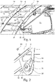
- Fig. 1 shows a structural system 2 for an aircraft in a spatial view.
- a plurality of circumferential stiffening frames 4 are shown. These provide a circumferentially closed contour and are arranged at a distance to each other along a longitudinal axis of the respective aircraft.
- the stiffening frames 4 comprise a web 6, an inner flange 8 and an outer flange 10.
- a skin 12 is arranged on the outer flanges 10 of all circumferential stiffening frames 4.
- longitudinal, axial stiffening elements 14 are provided, which cross the stiffening frames 4 and run through radial outer cutouts 16.
- the stiffening frames 4 comprise a first pattern 18 of drill holes 20 in the web 6. These drill holes allow to attach a first bracket 22 to the first pattern 18, exemplarily by bolts or screws.
- the first bracket 22 has a roughly triangular shape with a straight base attached to the web 6 and a circularly rounded tip that protrudes away from the frame 4.
- the first bracket 22 comprises an attachment device 26 having a rotatably supported sleeve 28 with an eccentric borehole 30.
- a connection element 32 can be inserted into the borehole 30 and will then assume a position given by the rotational position of the sleeve 28 adjustable and arrestable through an adjustment element 34.
- the connection element 32 is introduced into the piece of equipment 24 and connects it to the first bracket 22.
- By rotating the sleeve 28, the radial distance of the connection element 32 to the inner flange 8 is adjustable.
- the sleeve 28 is arrestable to maintain the adjusted rotational position. It may be useful to use a device exemplarily shown in EP3623646A1 .
- a second pattern 36 of drill holes 20 is arranged in a vertically distanced region of the stiffening frames 4.
- a second bracket 38 is attached.
- a first tie rod 40 having a variable length is connected to the second bracket 38 and the piece of equipment 24. Due to the position of the second pattern 36, the first tie rod 40 is oriented substantially horizontally. Thus, the piece of equipment 24 is supported in a lateral direction. For compensating manufacturing induced measure tolerances, the length of the first tie rod 40 is adjusted after installation.
- the axial stiffening elements 14 comprise a third pattern 42 of drill holes 20. It is adapted for receiving a third bracket 44, to which a second tie rod 46 is attached.
- the third brackets 44 are placed in one of the radial outer cutouts 16.
- the second tie rod 46 connects the third bracket 44 with the piece of equipment 24.
- the second tie rod 46 clearly extends clearly in an axial, longitudinal direction. Due to the use of a tie rod, a variable distance to the third bracket 44 can be assumed to provide for a tolerance compensation.
- an attachment device 26 is attached to the second bracket 38, such that the second bracket 38 is directly connectable to a piece of equipment 50.
- the piece of equipment 50 is modified and comprises a support frame 52. It is a rigid component, which comprises a first attachment region 53 having a first lug 54 protruding at an upper end in a vertical direction, as well as a second attachment region 55 having a second lug 56 extending at a lateral end in a lateral direction toward the skin 12.
- the first lug 54 is connected to the first bracket 22, while the second lug 56 is connected to the second bracket 38 through the attachment device 26.
- the support frame 52 comprises a central cutout 58, which is provided for reducing the weight of the support frame 52.
- the support frame 52 exemplarily comprises a bottom edge 60, which is oriented substantially horizontal, e.g. parallel to a cabin floor.
- the second tie rod 46 is attached to the third bracket 44 and a connecting element 62, which is attached to and exemplarily protrudes from the attachment device 26.
- a support in the longitudinal direction is provided.
- stiffening frames 4 exemplarily having two patterns 18 and 36 of drill holes 20 as well as axial stiffening elements 14 having a third pattern 42 of drill holes 20
- pieces of equipment may flexibly be installed without requiring the drilling of drill holes directly from inside the structure prior to installation of the pieces of equipment.
- Tolerance compensation may be conducted through the use of tie rods or the above mentioned attachment devices.
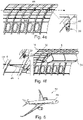
- Fig. 4a shows the stiffening frames 4 and the axial stiffening elements 14, which together with the skin 12 create an aircraft structure.
- first brackets 22, second brackets 38 and third brackets 44 are attached as previously shown in selected stiffening frames 4 and axial stiffening elements 14.
- the piece of equipment 50 is advanced to the first and second brackets 22 and 38.
- the attachment devices 26 are adjusted for tolerance compensation.
- the second tie rod 46 is installed and adjusted in its length.
- the process of fig. 4b is slightly modified for fixing the piece of equipment 24.
- the eccentric boreholes 30 of the attachment devices 26 are adjusted through the use of a laser beam 64 provided from an external source.
- the laser beam 64 comprises a defined spatial alignment to the structure and is used for aligning all the boreholes 32 this defined spatial alignment, such that the laser beam 64 extends through all first brackets 22 after the alignment.
- Figure 4f shows the attachment of the piece of equipment 24 afterwards.
- Fig. 5 shows an aircraft 66 having a fuselage 68 created by the structural system 2 or 48 together with the skin 12. Inside, a plurality of pieces of equipment 24 or 50 is installed.
Landscapes
- Engineering & Computer Science (AREA)
- Aviation & Aerospace Engineering (AREA)
- Mechanical Engineering (AREA)
- Connection Of Plates (AREA)
Abstract
Description
- The invention relates to a structural system for an aircraft and an aircraft having a structural system and at least one piece of equipment attachable to the structural system.
- In common aircraft design, circumferential stiffening frames as well as longitudinally arranged axial stiffening elements are provided to stiffen the outer skin of the aircraft fuselage. After connecting the skin, the stiffening frames, and the longitudinal stiffening elements to form a structure, fittings are attached to the stiffening frames and the stiffening elements to hold overhead stowage bins or the like. For this, often a laser beam aligned in the fuselage of the aircraft is used to manually align and drill drill holes for the fittings in a plurality of consecutive stiffening frames in order to provide an exact spatial alignment of the drill holes. The laser beam indicates an interface axis to the overhead stowage bins. While the drill holes are drilled, no other work is conducted inside the structure. Furthermore, this process is time-consuming.
- It is thus an object of the invention to propose a structural system for an aircraft that allows a faster attachment of pieces of equipment inside the aircraft structure, wherein the equipment is spatially alignable as exact as possible in the structure.
- This object is met by the structural system for an aircraft according to the features of claim 1. Advantageous improvements and further embodiments may be gathered from the subclaims and the following description.
- A structural system for an aircraft is proposed, comprising circumferential stiffening frames for stiffening a fuselage of the aircraft, the stiffening frames comprising a cross-sectional profile having a web enclosed by a radial inner flange and a radial outer flange, at least one first bracket, and at least one attachment device connectable to the at least one first bracket for fastening a piece of equipment to the at least one first bracket, wherein the stiffening frames each comprise a first pattern of drill holes adapted for receiving the at least one first bracket, wherein the at least one first bracket is adapted to protrude from the stiffening frames in a radial direction when attached, and wherein the attachment device is adapted for fastening the piece of equipment in a variable, arrestable distance to the respective first bracket.
- The circumferential stiffening frames are based on common circumferential stiffening frames. It is conceivable that the structural system comprises a plurality of stiffening frames in a staggered manner along the longitudinal axis of an aircraft, while they extend perpendicularly to the longitudinal axis. The circumferential stiffening frames may preferably comprise a circumferentially closed contour.
- The at least one circumferential stiffening frame comprises a cross-sectional profile having a web that substantially extends in a radial direction, i.e. perpendicular to the longitudinal axis of the aircraft. At the inner delimitation of the web, the inner flange is arranged. Together with the web it may create a T-shape or an L-shape. In the latter case, the inner flange may be arranged to extend only to a single side of the web. At an outer delimitation of the web, the outer flange may be provided, which may be designed in analogy to the inner flange. The cross-sectional profile may thus comprise a T-shape, an S-shape, a C-shape, or an intermediate shape.
- According to the invention, the circumferential stiffening frames each comprise the first pattern of drill holes. These are drilled into the stiffening frames before the installation of the frames. Thus, when the aircraft structure is created, the installation of pieces of equipment may be conducted by selecting stiffening at suitable positions to install one or a plurality of first brackets. Consequently, drill holes do not need to be drilled after directly before installation. Thus, the plurality of stiffening frames allow a flexible and fast installation. Unavoidable, manufacturing-induced measure tolerances can be compensated by the attachment device. This is adapted for adjusting and arresting a radial distance from the bracket that is fixed to the first pattern of drill holes. For example, it may comprise an eccentrical component, which is connectable to the piece of equipment and may be rotatable and arrestable. However, solutions with a thread or other length-variable devices may also be conceivable.
- The interior space of the aircraft structure, which comprises the structural system according to the above, is blocked for a clearly shorter time than with common installation procedures and structural setups. The structural system according to the invention thus allows a faster and more flexible installation of pieces of equipment.
- The structural system may further comprise at least one second bracket, wherein the stiffening frames each comprise a second pattern of drill holes adapted for receiving the at least one second bracket, and wherein the second pattern is arranged at a distance to the first pattern.
- The structural system may further comprise at least one support frame attachable to a piece of equipment, the at least one support frame having a first attachment region for connecting to the at least one first bracket and a having a second attachment region for connecting to a further connecting element. The support frame may be realized as a rigid component, which is attachable to a piece of equipment. It is conceivable that the support frame is directly attachable to the first bracket and the second attachment region, i.e. the further connecting element. Thus, the support frame may be aligned in the same plane as a single stiffening frame. For example, if the piece of equipment is an overhead stowage compartment, it may comprise a case or housing that encloses a stowage volume and has two end faces that will be aligned to either face forward or backward. The support frame may be directly attached to one of these end faces. The support frame may additionally be designed in such a way that at least one protruding lug or web is provided that is capable of connecting the support frame to the at least one first bracket and/or the further connecting element.
- The further connecting element may comprise the at least one second bracket in combination with the at least one attachment device. Thus, the support frame is directly connected to two brackets, wherein each of them comprises an attachment device that has a radial tolerance compensation feature.
- The support frame may have a substantially triangular shape. Therefore, one of the edges, i.e. a bottom edge, of the support frame may be aligned to run parallel to a floor in the cabin of the respective aircraft, the two other edges run from the bottom edge to a top peak that is connectable to the first bracket. The support frame may have a grid, stripe, or skeleton shape, in which as much material may be left out as possible to minimize the weight of the support frame.
- The structural system may further comprise axial stiffening elements, wherein the stiffening frames comprise radial outer cutouts for letting the axial stiffening elements pass through in a transverse direction to the respective stiffening frame, and wherein at least one of the axial stiffening elements comprises a third pattern of drill holes for receiving at least one third bracket. The axial stiffening elements, which may also be referred to as longitudinal stiffening elements or stringers, extend along the longitudinal axis of an aircraft structure on the inner surface of the aircraft skin. They also provide the possibility to attach a piece of equipment to the aircraft structure. As the axial stiffening elements extend along the longitudinal axis, they may be predestined for a providing a supporting force along a longitudinal axis.
- The structural system may further comprise a tie rod having a variable length and may be connectable to the at least one third bracket for supporting the piece of equipment in a longitudinal direction. A tie rod may simply be bolted to the third bracket and hold the piece of equipment in a variable distance. Hence, manufacturing induced tolerances can be compensated to align the respective piece of equipment in a spatially desired manner independent of measurement deviations of the aircraft structure.
- The attachment device may comprise a rotatable and arrestable sleeve having an eccentric borehole for tolerance compensation in a radial direction. By rotating the eccentric sleeve about the eccentric axis, a simple tolerance compensation preferably in a plane perpendicular to the longitudinal axis may be provided.
- It may be advantageous if the first pattern is arranged in a top region of the circumferential stiffening frames. Thus, the first pattern serves for attaching the respective piece of equipment in an upper region of the cabin at a clear distance from e.g. a cabin window or a central region of a lining segment. The first pattern may thus provide for a vertical support.
- Exemplarily, the second pattern may be arranged in a lateral region of the circumferential stiffening frames. The second pattern may thus serve for a support of the piece of equipment in a lateral direction.
- The invention further relates to an aircraft, having a structural system according to the above description and at least one piece of equipment attachable to at least one of the circumferential stiffening frames of the structural system through the at least one first bracket.
- In the aircraft, the at least one piece of equipment comprises an overhead stowage bin.
- Still further, the at least one piece of equipment may be attachable to the structural system through the at least one second bracket and/or the third bracket.
- Other characteristics, advantages and potential applications of the present invention result from the following description of the exemplary embodiments illustrated in the figures. In this respect, all described and/or graphically illustrated characteristics also form the object of the invention individually and in arbitrary combination regardless of their composition in the individual claims or their references to other claims. Furthermore, identical or similar objects are identified by the same reference symbols in the figures.
-
Fig. 1 and 2 show a structural system in two different views. -
Fig. 3 shows a structural system in a detail view. -
Fig. 4a to 4f show the process of installing the piece of equipment. -
Fig. 5 shows an aircraft. -
Fig. 1 shows astructural system 2 for an aircraft in a spatial view. Here, a plurality of circumferential stiffening frames 4 are shown. These provide a circumferentially closed contour and are arranged at a distance to each other along a longitudinal axis of the respective aircraft. The stiffening frames 4 comprise aweb 6, aninner flange 8 and anouter flange 10. Askin 12 is arranged on theouter flanges 10 of all circumferential stiffening frames 4. Thus, a hollow cylindrical fuselage structure is created. In addition, longitudinal,axial stiffening elements 14 are provided, which cross the stiffening frames 4 and run through radialouter cutouts 16. - The stiffening frames 4 comprise a
first pattern 18 of drill holes 20 in theweb 6. These drill holes allow to attach afirst bracket 22 to thefirst pattern 18, exemplarily by bolts or screws. Thefirst bracket 22 has a roughly triangular shape with a straight base attached to theweb 6 and a circularly rounded tip that protrudes away from theframe 4. A piece ofequipment 24, which is shown as an overhead stowage compartment, is directly attached to thefirst bracket 22 in its protruding part. - For compensating manufacturing-induced measurement tolerances, the
first bracket 22 comprises anattachment device 26 having a rotatably supportedsleeve 28 with aneccentric borehole 30. Aconnection element 32 can be inserted into theborehole 30 and will then assume a position given by the rotational position of thesleeve 28 adjustable and arrestable through anadjustment element 34. Theconnection element 32 is introduced into the piece ofequipment 24 and connects it to thefirst bracket 22. By rotating thesleeve 28, the radial distance of theconnection element 32 to theinner flange 8 is adjustable. Thesleeve 28 is arrestable to maintain the adjusted rotational position. It may be useful to use a device exemplarily shown inEP3623646A1 . - A
second pattern 36 of drill holes 20 is arranged in a vertically distanced region of the stiffening frames 4. Here, asecond bracket 38 is attached. Afirst tie rod 40 having a variable length is connected to thesecond bracket 38 and the piece ofequipment 24. Due to the position of thesecond pattern 36, thefirst tie rod 40 is oriented substantially horizontally. Thus, the piece ofequipment 24 is supported in a lateral direction. For compensating manufacturing induced measure tolerances, the length of thefirst tie rod 40 is adjusted after installation. - The
axial stiffening elements 14 comprise athird pattern 42 of drill holes 20. It is adapted for receiving athird bracket 44, to which asecond tie rod 46 is attached. Thethird brackets 44 are placed in one of the radialouter cutouts 16. Thesecond tie rod 46 connects thethird bracket 44 with the piece ofequipment 24. Thesecond tie rod 46 clearly extends clearly in an axial, longitudinal direction. Due to the use of a tie rod, a variable distance to thethird bracket 44 can be assumed to provide for a tolerance compensation. - In an alternative
structural system 48 shown inFig. 3 , anattachment device 26 is attached to thesecond bracket 38, such that thesecond bracket 38 is directly connectable to a piece ofequipment 50. In the shown example, the piece ofequipment 50 is modified and comprises asupport frame 52. It is a rigid component, which comprises afirst attachment region 53 having afirst lug 54 protruding at an upper end in a vertical direction, as well as asecond attachment region 55 having asecond lug 56 extending at a lateral end in a lateral direction toward theskin 12. Thefirst lug 54 is connected to thefirst bracket 22, while thesecond lug 56 is connected to thesecond bracket 38 through theattachment device 26. Thesupport frame 52 comprises acentral cutout 58, which is provided for reducing the weight of thesupport frame 52. Furthermore, thesupport frame 52 exemplarily comprises abottom edge 60, which is oriented substantially horizontal, e.g. parallel to a cabin floor. Thesecond tie rod 46 is attached to thethird bracket 44 and a connectingelement 62, which is attached to and exemplarily protrudes from theattachment device 26. Thus, a support in the longitudinal direction is provided. - By providing the stiffening frames 4 exemplarily having two
patterns axial stiffening elements 14 having athird pattern 42 of drill holes 20, pieces of equipment may flexibly be installed without requiring the drilling of drill holes directly from inside the structure prior to installation of the pieces of equipment. Tolerance compensation may be conducted through the use of tie rods or the above mentioned attachment devices. - In
fig. 4a to 4f , the process of attaching pieces of equipment is shown.Fig. 4a shows the stiffening frames 4 and theaxial stiffening elements 14, which together with theskin 12 create an aircraft structure. Infig. 4b ,first brackets 22,second brackets 38 andthird brackets 44 are attached as previously shown in selected stiffeningframes 4 andaxial stiffening elements 14. Infig. 4c , the piece ofequipment 50 is advanced to the first andsecond brackets fig. 4d , theattachment devices 26 are adjusted for tolerance compensation. Also, thesecond tie rod 46 is installed and adjusted in its length. Infig. 4e , the process offig. 4b is slightly modified for fixing the piece ofequipment 24. Here, theeccentric boreholes 30 of theattachment devices 26 are adjusted through the use of alaser beam 64 provided from an external source. Thelaser beam 64 comprises a defined spatial alignment to the structure and is used for aligning all theboreholes 32 this defined spatial alignment, such that thelaser beam 64 extends through allfirst brackets 22 after the alignment.Figure 4f shows the attachment of the piece ofequipment 24 afterwards. -
Fig. 5 shows anaircraft 66 having afuselage 68 created by thestructural system skin 12. Inside, a plurality of pieces ofequipment - In addition, it should be pointed out that "comprising" does not exclude other elements or steps, and "a" or "an" does not exclude a plural number. Furthermore, it should be pointed out that characteristics or steps which have been described with reference to one of the above exemplary embodiments may also be used in combination with other characteristics or steps of other exemplary embodiments described above. Reference characters in the claims are not to be interpreted as limitations.
-
- 2
- structural system
- 4
- circumferential stiffening frame
- 6
- web
- 8
- inner flange
- 10
- outer flange
- 12
- skin
- 14
- axial stiffening element
- 16
- radial outer cutout
- 18
- first pattern
- 20
- drill hole
- 22
- first bracket
- 24
- piece of equipment
- 26
- attachment device
- 28
- sleeve
- 30
- borehole32 connection element
- 34
- adjustment element
- 36
- second pattern
- 38
- second bracket
- 40
- first tie rod
- 42
- third pattern
- 44
- third bracket
- 46
- second tie rod
- 48
- structural system
- 50
- piece of equipment
- 52
- support frame
- 53
- first attachment region
- 54
- first lug
- 55
- second attachment region
- 56
- second lug
- 58
- central cutout
- 60
- bottom edge
- 62
- connecting element
- 64
- laser beam
- 66
- aircraft
- 68
- fuselage
Claims (13)
- A structural system (2, 48) for an aircraft (66), comprising
circumferential stiffening frames (6) for stiffening a fuselage (68) of the aircraft, the stiffening frames (6) comprising a cross-sectional profile having a web (6) enclosed by a radial inner flange (8) and a radial outer flange (10),
at least one first bracket (22), and
at least one attachment device (26) connectable to the at least one first bracket (22) for fastening a piece of equipment (24, 50) to the at least one first bracket (22),
wherein the stiffening frames (6) each comprise a first pattern (18) of drill holes (20) adapted for receiving the at least one first bracket (22),
wherein the at least one first bracket (22) is adapted to protrude from the stiffening frames (6) in a radial direction when attached, and
wherein the attachment device (26) is adapted for fastening the piece of equipment (24, 50) in a variable, arrestable distance to the respective first bracket (22). - The structural system (2, 48) of claim 1,
further comprising at least one second bracket (38),
wherein the stiffening frames (6) each comprise a second pattern (36) of drill holes (20) adapted for receiving the at least one second bracket (38), and
wherein the second pattern (36) is arranged at a distance to the first pattern (18). - The structural system (2, 48) of claim 1 or 2,
further comprising at least one support frame (6) attachable to a piece of equipment (24, 50),
the at least one support frame (6) having a first attachment region (53) for connecting to the at least one first bracket (22) and a having a second attachment region (55) for connecting to a further connecting element. - The structural system (2, 48) of claim 2 and 3,
wherein the further connecting element comprises the at least one second bracket (38) in combination with the at least one attachment device (26). - The structural system (2, 48) of claim 3 or 4,
wherein the support frame (6) has a substantially triangular shape. - The structural system (2, 48) of any of the preceding claims,
further comprising axial stiffening elements (14),
wherein the stiffening frames (6) comprise radial outer cutouts (16) for letting the axial stiffening elements (14) pass through in a transverse direction to the respective stiffening frame (6), and
wherein at least one of the axial stiffening elements (14) comprises a third pattern (42) of drill holes (20) for receiving at least one third bracket (44). - The structural system (2, 48) of claim 6,
further comprising a second tie rod (46) having a variable length and being connectable to the at least one third bracket (44) for supporting the piece of equipment (24, 50) in a longitudinal direction. - The structural system (2, 48) of any of the preceding claims,
wherein the attachment device (26) comprises a rotatable and arrestable sleeve (28) having an eccentric borehole (30) for tolerance compensation in a radial direction. - The structural system (2, 48) of any of the preceding claims,
wherein the first pattern (18) is arranged in a top region of the circumferential stiffening frames (6). - The structural system (2, 48) of claim 2,
wherein the second pattern (36) is arranged in a lateral region of the circumferential stiffening frames (6). - Aircraft (66), having a structural system (2, 48) according to any of the preceding claims and at least one piece of equipment (24, 50) attachable to at least one of the circumferential stiffening frames (6) of the structural system (2, 48) through the at least one first bracket (22).
- Aircraft (66) of claim 11, wherein the at least one piece of equipment (24, 50) comprises an overhead stowage bin.
- Aircraft (66) of claim 11 or 12, wherein the at least one piece of equipment (24, 50) is attachable to the structural system (2, 48) through the at least one second bracket (38) of claim 2 and/or the third bracket (44) of claim 6.
Priority Applications (1)
| Application Number | Priority Date | Filing Date | Title |
|---|---|---|---|
| EP21182980.9A EP4112443B1 (en) | 2021-06-30 | 2021-06-30 | Structural system for an aircraft for installation of equipment |
Applications Claiming Priority (1)
| Application Number | Priority Date | Filing Date | Title |
|---|---|---|---|
| EP21182980.9A EP4112443B1 (en) | 2021-06-30 | 2021-06-30 | Structural system for an aircraft for installation of equipment |
Publications (2)
| Publication Number | Publication Date |
|---|---|
| EP4112443A1 true EP4112443A1 (en) | 2023-01-04 |
| EP4112443B1 EP4112443B1 (en) | 2025-08-06 |
Family
ID=76730485
Family Applications (1)
| Application Number | Title | Priority Date | Filing Date |
|---|---|---|---|
| EP21182980.9A Active EP4112443B1 (en) | 2021-06-30 | 2021-06-30 | Structural system for an aircraft for installation of equipment |
Country Status (1)
| Country | Link |
|---|---|
| EP (1) | EP4112443B1 (en) |
Citations (5)
| Publication number | Priority date | Publication date | Assignee | Title |
|---|---|---|---|---|
| US5108048A (en) * | 1989-09-15 | 1992-04-28 | The Boeing Company | Stowage bin and support panel system for convertible aircraft and method of installation |
| US6883753B1 (en) * | 2004-03-25 | 2005-04-26 | The Boeing Company | Overhead bin and monument attachment support system |
| DE102011084722A1 (en) * | 2011-10-18 | 2013-04-18 | Airbus Operations Gmbh | Tie rod for connecting a fitting of equipment of an equipment module, in particular a luggage rack, to a structural fitting of a fuselage structure of an aircraft |
| US20190193871A1 (en) * | 2017-12-22 | 2019-06-27 | Airbus Operations Gmbh | Fastening system for fastening a component on a fuselage structure |
| EP3623646A1 (en) | 2018-09-13 | 2020-03-18 | Airbus (Sas) | Linking device with single shearing provided with an off-centre axis and an off-centre sleeve, mechanical assembly comprising such a device and assembly method |
-
2021
- 2021-06-30 EP EP21182980.9A patent/EP4112443B1/en active Active
Patent Citations (5)
| Publication number | Priority date | Publication date | Assignee | Title |
|---|---|---|---|---|
| US5108048A (en) * | 1989-09-15 | 1992-04-28 | The Boeing Company | Stowage bin and support panel system for convertible aircraft and method of installation |
| US6883753B1 (en) * | 2004-03-25 | 2005-04-26 | The Boeing Company | Overhead bin and monument attachment support system |
| DE102011084722A1 (en) * | 2011-10-18 | 2013-04-18 | Airbus Operations Gmbh | Tie rod for connecting a fitting of equipment of an equipment module, in particular a luggage rack, to a structural fitting of a fuselage structure of an aircraft |
| US20190193871A1 (en) * | 2017-12-22 | 2019-06-27 | Airbus Operations Gmbh | Fastening system for fastening a component on a fuselage structure |
| EP3623646A1 (en) | 2018-09-13 | 2020-03-18 | Airbus (Sas) | Linking device with single shearing provided with an off-centre axis and an off-centre sleeve, mechanical assembly comprising such a device and assembly method |
Also Published As
| Publication number | Publication date |
|---|---|
| EP4112443B1 (en) | 2025-08-06 |
Similar Documents
| Publication | Publication Date | Title |
|---|---|---|
| CN101309833B (en) | Attachment structure for securing internal equipment components of aircraft cabin | |
| US8528859B2 (en) | Installation system for an airplane | |
| EP3144223B1 (en) | Support system having a crown integration panel (cip) | |
| CN101249885B (en) | Rib support for wing panels | |
| CN101932504B (en) | Fuselage cell structure of an airplane for the simplified installation and attachment of fasteners for fastening conduits | |
| EP2493759B1 (en) | Fastening arrangement for fastening a component on a fuselage | |
| US20170247101A1 (en) | Unified floor and aircraft nose including such a floor, and method for incorporating such a nose | |
| EP3135585B1 (en) | Crown raceway support (crs) for crown integration panel (cip) | |
| US10053204B2 (en) | Adjustable support structure for aircraft cabin ceiling | |
| WO2009068107A1 (en) | Method of preparing the connection between two fuselage sections of an aircraft | |
| CN102666244A (en) | Ceiling panels with curtain rails in transport equipment cabins | |
| EP3495632A1 (en) | Integrated support structure for an aircraft engine and component parts thereof | |
| DE102010063076A1 (en) | Fastening arrangement and fastening fitting for attaching a component to a structural component of an aircraft or spacecraft | |
| EP3331757A1 (en) | Installation system for an aircraft | |
| EP3480110A1 (en) | Fastening arrangement for attaching a vehicle floor | |
| EP4112443B1 (en) | Structural system for an aircraft for installation of equipment | |
| EP4112444A1 (en) | Structural system for an aircraft for installation of equipment | |
| EP4403467A2 (en) | Carrier device, seating area divider and vehicle cabin | |
| EP2433861A2 (en) | Rear fuselage of an aircraft | |
| EP3620370A1 (en) | A support bracket for holding interior components of a vehicle | |
| EP4316984A1 (en) | Fastening structure for a monument and an overhead storage bin and vehicle | |
| US20210394907A1 (en) | Seat track fittings and methods for installing passenger seats in aircraft cabins using seat track fittings | |
| US11203403B2 (en) | Self-aligning structural attachment for crown integration panel (CIP) | |
| EP4112467B1 (en) | Mounting rail arrangement for an aircraft floor, floor structure and aircraft having the same | |
| EP2403058B1 (en) | Fixing adapter for a directional antenna |
Legal Events
| Date | Code | Title | Description |
|---|---|---|---|
| PUAI | Public reference made under article 153(3) epc to a published international application that has entered the european phase |
Free format text: ORIGINAL CODE: 0009012 |
|
| STAA | Information on the status of an ep patent application or granted ep patent |
Free format text: STATUS: THE APPLICATION HAS BEEN PUBLISHED |
|
| AK | Designated contracting states |
Kind code of ref document: A1 Designated state(s): AL AT BE BG CH CY CZ DE DK EE ES FI FR GB GR HR HU IE IS IT LI LT LU LV MC MK MT NL NO PL PT RO RS SE SI SK SM TR |
|
| STAA | Information on the status of an ep patent application or granted ep patent |
Free format text: STATUS: REQUEST FOR EXAMINATION WAS MADE |
|
| 17P | Request for examination filed |
Effective date: 20230627 |
|
| RBV | Designated contracting states (corrected) |
Designated state(s): AL AT BE BG CH CY CZ DE DK EE ES FI FR GB GR HR HU IE IS IT LI LT LU LV MC MK MT NL NO PL PT RO RS SE SI SK SM TR |
|
| STAA | Information on the status of an ep patent application or granted ep patent |
Free format text: STATUS: EXAMINATION IS IN PROGRESS |
|
| 17Q | First examination report despatched |
Effective date: 20240619 |
|
| 17Q | First examination report despatched |
Effective date: 20240626 |
|
| GRAP | Despatch of communication of intention to grant a patent |
Free format text: ORIGINAL CODE: EPIDOSNIGR1 |
|
| STAA | Information on the status of an ep patent application or granted ep patent |
Free format text: STATUS: GRANT OF PATENT IS INTENDED |
|
| INTG | Intention to grant announced |
Effective date: 20250508 |
|
| GRAS | Grant fee paid |
Free format text: ORIGINAL CODE: EPIDOSNIGR3 |
|
| GRAA | (expected) grant |
Free format text: ORIGINAL CODE: 0009210 |
|
| STAA | Information on the status of an ep patent application or granted ep patent |
Free format text: STATUS: THE PATENT HAS BEEN GRANTED |
|
| AK | Designated contracting states |
Kind code of ref document: B1 Designated state(s): AL AT BE BG CH CY CZ DE DK EE ES FI FR GB GR HR HU IE IS IT LI LT LU LV MC MK MT NL NO PL PT RO RS SE SI SK SM TR |
|
| REG | Reference to a national code |
Ref country code: GB Ref legal event code: FG4D |
|
| REG | Reference to a national code |
Ref country code: CH Ref legal event code: EP |
|
| REG | Reference to a national code |
Ref country code: IE Ref legal event code: FG4D |
|
| REG | Reference to a national code |
Ref country code: DE Ref legal event code: R096 Ref document number: 602021035473 Country of ref document: DE |
|
| REG | Reference to a national code |
Ref country code: NL Ref legal event code: MP Effective date: 20250806 |
|
| PG25 | Lapsed in a contracting state [announced via postgrant information from national office to epo] |
Ref country code: IS Free format text: LAPSE BECAUSE OF FAILURE TO SUBMIT A TRANSLATION OF THE DESCRIPTION OR TO PAY THE FEE WITHIN THE PRESCRIBED TIME-LIMIT Effective date: 20251206 |
|
| PG25 | Lapsed in a contracting state [announced via postgrant information from national office to epo] |
Ref country code: NO Free format text: LAPSE BECAUSE OF FAILURE TO SUBMIT A TRANSLATION OF THE DESCRIPTION OR TO PAY THE FEE WITHIN THE PRESCRIBED TIME-LIMIT Effective date: 20251106 |
|
| REG | Reference to a national code |
Ref country code: LT Ref legal event code: MG9D |
|
| PG25 | Lapsed in a contracting state [announced via postgrant information from national office to epo] |
Ref country code: PT Free format text: LAPSE BECAUSE OF FAILURE TO SUBMIT A TRANSLATION OF THE DESCRIPTION OR TO PAY THE FEE WITHIN THE PRESCRIBED TIME-LIMIT Effective date: 20251209 |
|
| PG25 | Lapsed in a contracting state [announced via postgrant information from national office to epo] |
Ref country code: FI Free format text: LAPSE BECAUSE OF FAILURE TO SUBMIT A TRANSLATION OF THE DESCRIPTION OR TO PAY THE FEE WITHIN THE PRESCRIBED TIME-LIMIT Effective date: 20250806 |
|
| PG25 | Lapsed in a contracting state [announced via postgrant information from national office to epo] |
Ref country code: NL Free format text: LAPSE BECAUSE OF FAILURE TO SUBMIT A TRANSLATION OF THE DESCRIPTION OR TO PAY THE FEE WITHIN THE PRESCRIBED TIME-LIMIT Effective date: 20250806 Ref country code: HR Free format text: LAPSE BECAUSE OF FAILURE TO SUBMIT A TRANSLATION OF THE DESCRIPTION OR TO PAY THE FEE WITHIN THE PRESCRIBED TIME-LIMIT Effective date: 20250806 |
|
| PG25 | Lapsed in a contracting state [announced via postgrant information from national office to epo] |
Ref country code: GR Free format text: LAPSE BECAUSE OF FAILURE TO SUBMIT A TRANSLATION OF THE DESCRIPTION OR TO PAY THE FEE WITHIN THE PRESCRIBED TIME-LIMIT Effective date: 20251107 |
|
| PG25 | Lapsed in a contracting state [announced via postgrant information from national office to epo] |
Ref country code: SE Free format text: LAPSE BECAUSE OF FAILURE TO SUBMIT A TRANSLATION OF THE DESCRIPTION OR TO PAY THE FEE WITHIN THE PRESCRIBED TIME-LIMIT Effective date: 20250806 |
|
| PG25 | Lapsed in a contracting state [announced via postgrant information from national office to epo] |
Ref country code: LV Free format text: LAPSE BECAUSE OF FAILURE TO SUBMIT A TRANSLATION OF THE DESCRIPTION OR TO PAY THE FEE WITHIN THE PRESCRIBED TIME-LIMIT Effective date: 20250806 |
|
| PG25 | Lapsed in a contracting state [announced via postgrant information from national office to epo] |
Ref country code: BG Free format text: LAPSE BECAUSE OF FAILURE TO SUBMIT A TRANSLATION OF THE DESCRIPTION OR TO PAY THE FEE WITHIN THE PRESCRIBED TIME-LIMIT Effective date: 20250806 Ref country code: PL Free format text: LAPSE BECAUSE OF FAILURE TO SUBMIT A TRANSLATION OF THE DESCRIPTION OR TO PAY THE FEE WITHIN THE PRESCRIBED TIME-LIMIT Effective date: 20250806 |
|
| PG25 | Lapsed in a contracting state [announced via postgrant information from national office to epo] |
Ref country code: RS Free format text: LAPSE BECAUSE OF FAILURE TO SUBMIT A TRANSLATION OF THE DESCRIPTION OR TO PAY THE FEE WITHIN THE PRESCRIBED TIME-LIMIT Effective date: 20251106 |
|
| PG25 | Lapsed in a contracting state [announced via postgrant information from national office to epo] |
Ref country code: ES Free format text: LAPSE BECAUSE OF FAILURE TO SUBMIT A TRANSLATION OF THE DESCRIPTION OR TO PAY THE FEE WITHIN THE PRESCRIBED TIME-LIMIT Effective date: 20250806 |
|
| REG | Reference to a national code |
Ref country code: AT Ref legal event code: MK05 Ref document number: 1821570 Country of ref document: AT Kind code of ref document: T Effective date: 20250806 |
|
| PG25 | Lapsed in a contracting state [announced via postgrant information from national office to epo] |
Ref country code: SM Free format text: LAPSE BECAUSE OF FAILURE TO SUBMIT A TRANSLATION OF THE DESCRIPTION OR TO PAY THE FEE WITHIN THE PRESCRIBED TIME-LIMIT Effective date: 20250806 |
|
| PG25 | Lapsed in a contracting state [announced via postgrant information from national office to epo] |
Ref country code: DK Free format text: LAPSE BECAUSE OF FAILURE TO SUBMIT A TRANSLATION OF THE DESCRIPTION OR TO PAY THE FEE WITHIN THE PRESCRIBED TIME-LIMIT Effective date: 20250806 |
|
| PG25 | Lapsed in a contracting state [announced via postgrant information from national office to epo] |
Ref country code: AT Free format text: LAPSE BECAUSE OF FAILURE TO SUBMIT A TRANSLATION OF THE DESCRIPTION OR TO PAY THE FEE WITHIN THE PRESCRIBED TIME-LIMIT Effective date: 20250806 |
|
| PG25 | Lapsed in a contracting state [announced via postgrant information from national office to epo] |
Ref country code: IT Free format text: LAPSE BECAUSE OF FAILURE TO SUBMIT A TRANSLATION OF THE DESCRIPTION OR TO PAY THE FEE WITHIN THE PRESCRIBED TIME-LIMIT Effective date: 20250806 |
|
| PG25 | Lapsed in a contracting state [announced via postgrant information from national office to epo] |
Ref country code: CZ Free format text: LAPSE BECAUSE OF FAILURE TO SUBMIT A TRANSLATION OF THE DESCRIPTION OR TO PAY THE FEE WITHIN THE PRESCRIBED TIME-LIMIT Effective date: 20250806 |
|
| PG25 | Lapsed in a contracting state [announced via postgrant information from national office to epo] |
Ref country code: EE Free format text: LAPSE BECAUSE OF FAILURE TO SUBMIT A TRANSLATION OF THE DESCRIPTION OR TO PAY THE FEE WITHIN THE PRESCRIBED TIME-LIMIT Effective date: 20250806 Ref country code: SK Free format text: LAPSE BECAUSE OF FAILURE TO SUBMIT A TRANSLATION OF THE DESCRIPTION OR TO PAY THE FEE WITHIN THE PRESCRIBED TIME-LIMIT Effective date: 20250806 |