EP4112345A1 - Drop-off assist device, drop-off assist method, and non-transitory storage medium - Google Patents
Drop-off assist device, drop-off assist method, and non-transitory storage medium Download PDFInfo
- Publication number
- EP4112345A1 EP4112345A1 EP22180408.1A EP22180408A EP4112345A1 EP 4112345 A1 EP4112345 A1 EP 4112345A1 EP 22180408 A EP22180408 A EP 22180408A EP 4112345 A1 EP4112345 A1 EP 4112345A1
- Authority
- EP
- European Patent Office
- Prior art keywords
- target
- speed
- predetermined
- drop
- host vehicle
- Prior art date
- Legal status (The legal status is an assumption and is not a legal conclusion. Google has not performed a legal analysis and makes no representation as to the accuracy of the status listed.)
- Granted
Links
Images
Classifications
-
- B—PERFORMING OPERATIONS; TRANSPORTING
- B60—VEHICLES IN GENERAL
- B60W—CONJOINT CONTROL OF VEHICLE SUB-UNITS OF DIFFERENT TYPE OR DIFFERENT FUNCTION; CONTROL SYSTEMS SPECIALLY ADAPTED FOR HYBRID VEHICLES; ROAD VEHICLE DRIVE CONTROL SYSTEMS FOR PURPOSES NOT RELATED TO THE CONTROL OF A PARTICULAR SUB-UNIT
- B60W30/00—Purposes of road vehicle drive control systems not related to the control of a particular sub-unit, e.g. of systems using conjoint control of vehicle sub-units
- B60W30/08—Active safety systems predicting or avoiding probable or impending collision or attempting to minimise its consequences
- B60W30/09—Taking automatic action to avoid collision, e.g. braking and steering
-
- B—PERFORMING OPERATIONS; TRANSPORTING
- B60—VEHICLES IN GENERAL
- B60R—VEHICLES, VEHICLE FITTINGS, OR VEHICLE PARTS, NOT OTHERWISE PROVIDED FOR
- B60R21/00—Arrangements or fittings on vehicles for protecting or preventing injuries to occupants or pedestrians in case of accidents or other traffic risks
- B60R21/01—Electrical circuits for triggering passive safety arrangements, e.g. airbags, safety belt tighteners, in case of vehicle accidents or impending vehicle accidents
- B60R21/013—Electrical circuits for triggering passive safety arrangements, e.g. airbags, safety belt tighteners, in case of vehicle accidents or impending vehicle accidents including means for detecting collisions, impending collisions or roll-over
- B60R21/0134—Electrical circuits for triggering passive safety arrangements, e.g. airbags, safety belt tighteners, in case of vehicle accidents or impending vehicle accidents including means for detecting collisions, impending collisions or roll-over responsive to imminent contact with an obstacle, e.g. using radar systems
-
- B—PERFORMING OPERATIONS; TRANSPORTING
- B60—VEHICLES IN GENERAL
- B60W—CONJOINT CONTROL OF VEHICLE SUB-UNITS OF DIFFERENT TYPE OR DIFFERENT FUNCTION; CONTROL SYSTEMS SPECIALLY ADAPTED FOR HYBRID VEHICLES; ROAD VEHICLE DRIVE CONTROL SYSTEMS FOR PURPOSES NOT RELATED TO THE CONTROL OF A PARTICULAR SUB-UNIT
- B60W30/00—Purposes of road vehicle drive control systems not related to the control of a particular sub-unit, e.g. of systems using conjoint control of vehicle sub-units
- B60W30/08—Active safety systems predicting or avoiding probable or impending collision or attempting to minimise its consequences
- B60W30/095—Predicting travel path or likelihood of collision
- B60W30/0956—Predicting travel path or likelihood of collision the prediction being responsive to traffic or environmental parameters
-
- B—PERFORMING OPERATIONS; TRANSPORTING
- B60—VEHICLES IN GENERAL
- B60J—WINDOWS, WINDSCREENS, NON-FIXED ROOFS, DOORS, OR SIMILAR DEVICES FOR VEHICLES; REMOVABLE EXTERNAL PROTECTIVE COVERINGS SPECIALLY ADAPTED FOR VEHICLES
- B60J5/00—Doors
- B60J5/04—Doors arranged at the vehicle sides
-
- B—PERFORMING OPERATIONS; TRANSPORTING
- B60—VEHICLES IN GENERAL
- B60Q—ARRANGEMENT OF SIGNALLING OR LIGHTING DEVICES, THE MOUNTING OR SUPPORTING THEREOF OR CIRCUITS THEREFOR, FOR VEHICLES IN GENERAL
- B60Q9/00—Arrangement or adaptation of signal devices not provided for in one of main groups B60Q1/00 - B60Q7/00, e.g. haptic signalling
- B60Q9/008—Arrangement or adaptation of signal devices not provided for in one of main groups B60Q1/00 - B60Q7/00, e.g. haptic signalling for anti-collision purposes
-
- B—PERFORMING OPERATIONS; TRANSPORTING
- B60—VEHICLES IN GENERAL
- B60R—VEHICLES, VEHICLE FITTINGS, OR VEHICLE PARTS, NOT OTHERWISE PROVIDED FOR
- B60R21/00—Arrangements or fittings on vehicles for protecting or preventing injuries to occupants or pedestrians in case of accidents or other traffic risks
- B60R21/02—Occupant safety arrangements or fittings, e.g. crash pads
-
- B—PERFORMING OPERATIONS; TRANSPORTING
- B60—VEHICLES IN GENERAL
- B60W—CONJOINT CONTROL OF VEHICLE SUB-UNITS OF DIFFERENT TYPE OR DIFFERENT FUNCTION; CONTROL SYSTEMS SPECIALLY ADAPTED FOR HYBRID VEHICLES; ROAD VEHICLE DRIVE CONTROL SYSTEMS FOR PURPOSES NOT RELATED TO THE CONTROL OF A PARTICULAR SUB-UNIT
- B60W50/00—Details of control systems for road vehicle drive control not related to the control of a particular sub-unit, e.g. process diagnostic or vehicle driver interfaces
- B60W50/0098—Details of control systems ensuring comfort, safety or stability not otherwise provided for
-
- B—PERFORMING OPERATIONS; TRANSPORTING
- B60—VEHICLES IN GENERAL
- B60W—CONJOINT CONTROL OF VEHICLE SUB-UNITS OF DIFFERENT TYPE OR DIFFERENT FUNCTION; CONTROL SYSTEMS SPECIALLY ADAPTED FOR HYBRID VEHICLES; ROAD VEHICLE DRIVE CONTROL SYSTEMS FOR PURPOSES NOT RELATED TO THE CONTROL OF A PARTICULAR SUB-UNIT
- B60W50/00—Details of control systems for road vehicle drive control not related to the control of a particular sub-unit, e.g. process diagnostic or vehicle driver interfaces
- B60W50/08—Interaction between the driver and the control system
- B60W50/14—Means for informing the driver, warning the driver or prompting a driver intervention
-
- E—FIXED CONSTRUCTIONS
- E05—LOCKS; KEYS; WINDOW OR DOOR FITTINGS; SAFES
- E05B—LOCKS; ACCESSORIES THEREFOR; HANDCUFFS
- E05B77/00—Vehicle locks characterised by special functions or purposes
- E05B77/02—Vehicle locks characterised by special functions or purposes for accident situations
-
- E—FIXED CONSTRUCTIONS
- E05—LOCKS; KEYS; WINDOW OR DOOR FITTINGS; SAFES
- E05B—LOCKS; ACCESSORIES THEREFOR; HANDCUFFS
- E05B77/00—Vehicle locks characterised by special functions or purposes
- E05B77/22—Functions related to actuation of locks from the passenger compartment of the vehicle
- E05B77/24—Functions related to actuation of locks from the passenger compartment of the vehicle preventing use of an inner door handle, sill button, lock knob or the like
-
- E—FIXED CONSTRUCTIONS
- E05—LOCKS; KEYS; WINDOW OR DOOR FITTINGS; SAFES
- E05F—DEVICES FOR MOVING WINGS INTO OPEN OR CLOSED POSITION; CHECKS FOR WINGS; WING FITTINGS NOT OTHERWISE PROVIDED FOR, CONCERNED WITH THE FUNCTIONING OF THE WING
- E05F15/00—Power-operated mechanisms for wings
- E05F15/40—Safety devices, e.g. detection of obstructions or end positions
-
- E—FIXED CONSTRUCTIONS
- E05—LOCKS; KEYS; WINDOW OR DOOR FITTINGS; SAFES
- E05F—DEVICES FOR MOVING WINGS INTO OPEN OR CLOSED POSITION; CHECKS FOR WINGS; WING FITTINGS NOT OTHERWISE PROVIDED FOR, CONCERNED WITH THE FUNCTIONING OF THE WING
- E05F15/00—Power-operated mechanisms for wings
- E05F15/40—Safety devices, e.g. detection of obstructions or end positions
- E05F15/42—Detection using safety edges
-
- G—PHYSICS
- G01—MEASURING; TESTING
- G01S—RADIO DIRECTION-FINDING; RADIO NAVIGATION; DETERMINING DISTANCE OR VELOCITY BY USE OF RADIO WAVES; LOCATING OR PRESENCE-DETECTING BY USE OF THE REFLECTION OR RERADIATION OF RADIO WAVES; ANALOGOUS ARRANGEMENTS USING OTHER WAVES
- G01S13/00—Systems using the reflection or reradiation of radio waves, e.g. radar systems; Analogous systems using reflection or reradiation of waves whose nature or wavelength is irrelevant or unspecified
- G01S13/88—Radar or analogous systems specially adapted for specific applications
- G01S13/93—Radar or analogous systems specially adapted for specific applications for anti-collision purposes
- G01S13/931—Radar or analogous systems specially adapted for specific applications for anti-collision purposes of land vehicles
-
- B—PERFORMING OPERATIONS; TRANSPORTING
- B60—VEHICLES IN GENERAL
- B60W—CONJOINT CONTROL OF VEHICLE SUB-UNITS OF DIFFERENT TYPE OR DIFFERENT FUNCTION; CONTROL SYSTEMS SPECIALLY ADAPTED FOR HYBRID VEHICLES; ROAD VEHICLE DRIVE CONTROL SYSTEMS FOR PURPOSES NOT RELATED TO THE CONTROL OF A PARTICULAR SUB-UNIT
- B60W50/00—Details of control systems for road vehicle drive control not related to the control of a particular sub-unit, e.g. process diagnostic or vehicle driver interfaces
- B60W2050/0062—Adapting control system settings
- B60W2050/0075—Automatic parameter input, automatic initialising or calibrating means
- B60W2050/0083—Setting, resetting, calibration
-
- B—PERFORMING OPERATIONS; TRANSPORTING
- B60—VEHICLES IN GENERAL
- B60W—CONJOINT CONTROL OF VEHICLE SUB-UNITS OF DIFFERENT TYPE OR DIFFERENT FUNCTION; CONTROL SYSTEMS SPECIALLY ADAPTED FOR HYBRID VEHICLES; ROAD VEHICLE DRIVE CONTROL SYSTEMS FOR PURPOSES NOT RELATED TO THE CONTROL OF A PARTICULAR SUB-UNIT
- B60W50/00—Details of control systems for road vehicle drive control not related to the control of a particular sub-unit, e.g. process diagnostic or vehicle driver interfaces
- B60W50/08—Interaction between the driver and the control system
- B60W50/14—Means for informing the driver, warning the driver or prompting a driver intervention
- B60W2050/143—Alarm means
-
- B—PERFORMING OPERATIONS; TRANSPORTING
- B60—VEHICLES IN GENERAL
- B60W—CONJOINT CONTROL OF VEHICLE SUB-UNITS OF DIFFERENT TYPE OR DIFFERENT FUNCTION; CONTROL SYSTEMS SPECIALLY ADAPTED FOR HYBRID VEHICLES; ROAD VEHICLE DRIVE CONTROL SYSTEMS FOR PURPOSES NOT RELATED TO THE CONTROL OF A PARTICULAR SUB-UNIT
- B60W50/00—Details of control systems for road vehicle drive control not related to the control of a particular sub-unit, e.g. process diagnostic or vehicle driver interfaces
- B60W50/08—Interaction between the driver and the control system
- B60W50/14—Means for informing the driver, warning the driver or prompting a driver intervention
- B60W2050/146—Display means
-
- B—PERFORMING OPERATIONS; TRANSPORTING
- B60—VEHICLES IN GENERAL
- B60W—CONJOINT CONTROL OF VEHICLE SUB-UNITS OF DIFFERENT TYPE OR DIFFERENT FUNCTION; CONTROL SYSTEMS SPECIALLY ADAPTED FOR HYBRID VEHICLES; ROAD VEHICLE DRIVE CONTROL SYSTEMS FOR PURPOSES NOT RELATED TO THE CONTROL OF A PARTICULAR SUB-UNIT
- B60W2420/00—Indexing codes relating to the type of sensors based on the principle of their operation
- B60W2420/40—Photo, light or radio wave sensitive means, e.g. infrared sensors
- B60W2420/408—Radar; Laser, e.g. lidar
-
- B—PERFORMING OPERATIONS; TRANSPORTING
- B60—VEHICLES IN GENERAL
- B60W—CONJOINT CONTROL OF VEHICLE SUB-UNITS OF DIFFERENT TYPE OR DIFFERENT FUNCTION; CONTROL SYSTEMS SPECIALLY ADAPTED FOR HYBRID VEHICLES; ROAD VEHICLE DRIVE CONTROL SYSTEMS FOR PURPOSES NOT RELATED TO THE CONTROL OF A PARTICULAR SUB-UNIT
- B60W2520/00—Input parameters relating to overall vehicle dynamics
- B60W2520/04—Vehicle stop
-
- B—PERFORMING OPERATIONS; TRANSPORTING
- B60—VEHICLES IN GENERAL
- B60W—CONJOINT CONTROL OF VEHICLE SUB-UNITS OF DIFFERENT TYPE OR DIFFERENT FUNCTION; CONTROL SYSTEMS SPECIALLY ADAPTED FOR HYBRID VEHICLES; ROAD VEHICLE DRIVE CONTROL SYSTEMS FOR PURPOSES NOT RELATED TO THE CONTROL OF A PARTICULAR SUB-UNIT
- B60W2554/00—Input parameters relating to objects
- B60W2554/40—Dynamic objects, e.g. animals, windblown objects
- B60W2554/402—Type
- B60W2554/4026—Cycles
-
- B—PERFORMING OPERATIONS; TRANSPORTING
- B60—VEHICLES IN GENERAL
- B60W—CONJOINT CONTROL OF VEHICLE SUB-UNITS OF DIFFERENT TYPE OR DIFFERENT FUNCTION; CONTROL SYSTEMS SPECIALLY ADAPTED FOR HYBRID VEHICLES; ROAD VEHICLE DRIVE CONTROL SYSTEMS FOR PURPOSES NOT RELATED TO THE CONTROL OF A PARTICULAR SUB-UNIT
- B60W2554/00—Input parameters relating to objects
- B60W2554/80—Spatial relation or speed relative to objects
-
- E—FIXED CONSTRUCTIONS
- E05—LOCKS; KEYS; WINDOW OR DOOR FITTINGS; SAFES
- E05F—DEVICES FOR MOVING WINGS INTO OPEN OR CLOSED POSITION; CHECKS FOR WINGS; WING FITTINGS NOT OTHERWISE PROVIDED FOR, CONCERNED WITH THE FUNCTIONING OF THE WING
- E05F15/00—Power-operated mechanisms for wings
- E05F15/40—Safety devices, e.g. detection of obstructions or end positions
- E05F15/42—Detection using safety edges
- E05F2015/483—Detection using safety edges for detection during opening
-
- G—PHYSICS
- G01—MEASURING; TESTING
- G01S—RADIO DIRECTION-FINDING; RADIO NAVIGATION; DETERMINING DISTANCE OR VELOCITY BY USE OF RADIO WAVES; LOCATING OR PRESENCE-DETECTING BY USE OF THE REFLECTION OR RERADIATION OF RADIO WAVES; ANALOGOUS ARRANGEMENTS USING OTHER WAVES
- G01S13/00—Systems using the reflection or reradiation of radio waves, e.g. radar systems; Analogous systems using reflection or reradiation of waves whose nature or wavelength is irrelevant or unspecified
- G01S13/88—Radar or analogous systems specially adapted for specific applications
- G01S13/93—Radar or analogous systems specially adapted for specific applications for anti-collision purposes
- G01S13/931—Radar or analogous systems specially adapted for specific applications for anti-collision purposes of land vehicles
- G01S2013/9315—Monitoring blind spots
Definitions
- the present invention relates to a drop-off assist device, a drop-off assist method, and a non-transitory storage medium.
- the drop-off assist device capable of executing drop-off assist control to assist safe drop-off of an occupant of a vehicle (typically, an automobile).
- the drop-off assist device executes the drop-off assist control when an occupant's drop-off intention (typically, an occupant's door opening operation) is detected in a case where an obstructive target that may hinder the occupant's safe drop-off (in other words, pass by the side of the vehicle) is detected while the vehicle is stopped (see Japanese Unexamined Patent Application Publication No. 2007-138457 ( JP 2007-138457 A )).
- the vehicle including the drop-off assist device is hereinafter referred to as "host vehicle”.
- the drop-off assist device detects the obstructive target as follows.
- the drop-off assist device includes a target information acquisition device (for example, a radar sensor) that can detect a target present in a region rearward of the host vehicle and acquire information about the target as target information.
- the drop-off assist device calculates, based on the target information acquired from the target information acquisition device, a predicted time required for the target to come into contact with or to come into close proximity to the host vehicle (time to collision; hereinafter referred to also as "TTC").
- TTC time to collision
- the drop-off assist device determines that the target may hinder the occupant's safe drop-off, and detects the target as the obstructive target.
- the TTCth is determined based on a stopping time of the target.
- the stopping time is a time from a timing when a driver of the target senses danger (for example, when the driver recognizes a drop-off action of the occupant of the vehicle) to a timing when the target stops after the driver starts braking (starts to apply a brake).
- the stopping time is the sum of a free running time and a braking time.
- the stopping time may be a limit value of a time within which the target can avoid contact with or close proximity to the host vehicle.
- the stopping time is hereinafter referred to also as "avoidance limit time".
- avoidance limit time By determining the TTCth based on the avoidance limit time (stopping time), unnecessary drop-off assist control is not executed when the target can avoid contact with or close proximity to the host vehicle by braking.
- the avoidance limit time varies depending on the type of the target.
- typical vehicles that may be obstructive targets such as an automobile, a motorcycle, a motorized bicycle, and a bicycle
- the bicycle has the longest avoidance limit time.
- the avoidance limit time There is no much difference in the avoidance limit time among the other vehicles. Therefore, the TTCth is generally determined based on the avoidance limit time of the bicycle that is the maximum value.
- the drop-off assist control can be executed at an appropriate timing in a case where the target is a bicycle.
- the target is any other vehicle (that is, an automobile, a motorcycle, or a motorized bicycle)
- a value significantly larger than the avoidance limit time of this vehicle is set as the TTCth. Therefore, when the TTC of this vehicle is equal to or smaller than the TTCth though the TTC is sufficiently larger than the avoidance limit time (in other words, when the driver senses danger at this timing and starts braking, the vehicle may sufficiently avoid contact with or close proximity to the host vehicle), the vehicle is detected as the obstructive target and the drop-off assist control is executed.
- the drop-off assist control is executed for the vehicles other than the bicycle at a timing significantly earlier than the timing when the drop-off assist control is actually required. Therefore, a problem may arise in that unnecessary drop-off assist control is executed.
- the drop-off assist device calculates the TTC of the target. This calculation process is performed only for a target that may pass by the side of the host vehicle in the future among the targets detected by the target information acquisition device. Specifically, the drop-off assist device calculates moving directions of the detected targets based on the target information. When an extension line in the moving direction of any target passes by the side of the host vehicle, the TTC of this target is calculated.
- the current performance of the target information acquisition device has a limit in terms of the detection accuracy for a distant target. Therefore, the target information of the distant target is likely to include a deviation. As a result, a deviation is likely to occur in the result of calculation of the moving direction of the target.
- vehicles other than the bicycle travel at speeds higher than that of the bicycle. Therefore, the detection of the vehicle other than the bicycle by the target information acquisition device needs to be started when the vehicle is located far behind the host vehicle. In this case, a deviation is likely to occur in the result of calculation of the moving direction of the vehicle.
- the extension line in the moving direction may pass by the side of the host vehicle and the TTC may be calculated even though the vehicle is not actually the target of TTC calculation (that is, there is no possibility of passing by the side of the host vehicle in the future).
- TTC ⁇ TTCth easily holds when the TTCth is set to a relatively large value. Therefore, there is a strong possibility that a vehicle other than the bicycle is erroneously detected as the obstructive target. Thus, a problem may arise in that unnecessary drop-off assist control is executed.
- the present invention provides a drop-off assist device capable of suppressing unnecessary execution of drop-off assist control.
- a drop-off assist device includes a target information acquisition sensor configured to detect a target present in a region rearward of a host vehicle, and acquire information about the detected target as target information; and an electronic control unit configured to, while the host vehicle is stopped, calculate, based on the target information, a predicted time required for the target to come into contact with or to come into close proximity to the host vehicle, and execute drop-off assist control for assisting drop-off of an occupant of the host vehicle when the predicted time is equal to or smaller than a predetermined time threshold, set the predetermined time threshold to a predetermined first time threshold when a speed of the detected target is equal to or lower than a predetermined first speed, and set the predetermined time threshold to a value smaller than the predetermined first time threshold when the speed of the detected target is higher than the predetermined first speed.
- the time threshold (time threshold of the predicted time to be used for determining whether the drop-off assist control needs to be executed) is set to the first time threshold.
- the time threshold is set to the value smaller than the first time threshold.
- an avoidance limit time (stopping time) of a vehicle other than a bicycle typically, an automobile, a motorcycle, or a motorized bicycle is shorter than an avoidance limit time of the bicycle.
- the time threshold in a case where the target is the vehicle other than the bicycle can be set to the value smaller than the time threshold in a case where the target is the bicycle.
- the start timing of the drop-off assist control can be delayed to an appropriate timing when the target is the vehicle other than the bicycle, as compared with a configuration in which the time threshold is uniformly determined based on the avoidance limit time of the bicycle.
- the predetermined first speed may be set based on a speed distribution of a bicycle traveling on a road; and the predetermined first time threshold may be set based on an avoidance limit time of the bicycle at a speed within a predetermined first speed range.
- the avoidance limit time is a limit value of a time within which the target is capable of avoiding the contact with or the close proximity to the host vehicle.
- the first speed and the first time threshold can be set to appropriate values.
- the first speed range is, for example, an average speed range when the bicycle travels on the road.
- the electronic control unit may be configured to set the predetermined time threshold to a predetermined second time threshold smaller than the predetermined first time threshold when the speed of the detected target is higher than a predetermined second speed higher than the predetermined first speed.
- the predetermined second speed may be set based on a speed distribution of the target other than a bicycle traveling on a road; and the predetermined second time threshold may be set based on an avoidance limit time of the target other than the bicycle at a speed within a predetermined second speed range.
- the avoidance limit time is a limit value of a time within which the target is capable of avoiding the contact with or the close proximity to the host vehicle.
- the second speed and the second time threshold can be set to appropriate values.
- the second speed range is, for example, an average speed range when the vehicle other than the bicycle travels on the road.
- the electronic control unit may be configured to, when the electronic control unit determines that the occupant intends to drop off and while the host vehicle is stopped, calculate the predicted time, and execute the drop-off assist control when the predicted time is equal to or smaller than the predetermined time threshold.
- the drop-off assist control may be control of the electronic control unit to generate an alert.
- the drop-off assist control may be control of the electronic control unit to limit a degree of door opening.
- the drop-off assist control may be control of the electronic control unit to lock a door.
- the electronic control unit may be configured to execute the drop-off assist control when the predicted time is equal to or smaller than the predetermined time threshold continuously for a predetermined period.
- a drop-off assist method includes detecting a target present in a region rearward of a host vehicle; acquiring information about the detected target as target information; and while the host vehicle is stopped, i) calculating, based on the target information, a predicted time required for the target to come into contact with or to come into close proximity to the host vehicle; ii) setting a predetermined time threshold to a predetermined first time threshold when a speed of the detected target is equal to or lower than a predetermined first speed; iii) setting the predetermined time threshold to a value smaller than the predetermined first time threshold when the speed of the detected target is higher than the predetermined first speed; and iv) executing drop-off assist control for assisting drop-off of an occupant of the host vehicle when the predicted time is equal to or smaller than the predetermined time threshold.
- a non-transitory storage medium stores instructions that are executable by one or more processors and that cause the one or more processors to perform functions.
- the functions include detecting a target present in a region rearward of a host vehicle; acquiring information about the detected target as target information; and while the host vehicle is stopped, i) calculating, based on the target information, a predicted time required for the target to come into contact with or to come into close proximity to the host vehicle; ii) setting a predetermined time threshold to a predetermined first time threshold when a speed of the detected target is equal to or lower than a predetermined first speed; iii) setting the predetermined time threshold to a value smaller than the predetermined first time threshold when the speed of the detected target is higher than the predetermined first speed; and iv) executing drop-off assist control for assisting drop-off of an occupant of the host vehicle when the predicted time is equal to or smaller than the predetermined time threshold.
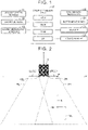
- the present embodiment device includes a drop-off assist ECU 10 and a vehicle speed sensor 11, a radar sensor 12, door open/close sensors 13, side mirror indicators 20, an instrument panel 21, a buzzer 22, and a loudspeaker 23 that are connected to the drop-off assist ECU 10.
- the drop-off assist ECU 10 includes a microcomputer as a main component.
- the ECU is an abbreviation for "electronic control unit”.
- the microcomputer includes a CPU, a read-only memory (ROM), a random-access memory (RAM), an interface (I/F), and the like, and the CPU implements various functions by executing instructions (programs or routines) stored in the ROM.
- the vehicle including the present embodiment device is hereinafter referred to as "host vehicle”.
- the drop-off assist ECU 10 acquires signals generated or output by the sensors 11 to 13 every time a predetermined time elapses, and controls the elements (devices) 20 to 23 based on the acquired signals.
- the drop-off assist ECU 10 is hereinafter referred to simply as "ECU 10" as well.
- the vehicle speed sensor 11 generates a signal based on a traveling speed of the host vehicle (hereinafter referred to as "vehicle speed").
- vehicle speed a traveling speed of the host vehicle
- the ECU 10 acquires the signal generated by the vehicle speed sensor 11 and calculates the vehicle speed based on the signal. When the vehicle speed is zero, the ECU 10 determines that the host vehicle is in a stopped state (hereinafter referred to also as “while the vehicle is stopped").
- the radar sensor 12 has a function of acquiring information about a three-dimensional object (target) present in a region rearward (a region behind the vehicle or the sides of a region behind the vehicle) of the host vehicle.
- the three-dimensional object is a moving object such as a vehicle or a pedestrian.
- the vehicle includes an automobile, a motorcycle, a motorized bicycle, and a bicycle.
- the radar sensor 12 includes a left radar sensor 12L provided at a left corner of a rear bumper (not shown in drawings) of a host vehicle V, and a right radar sensor 12R provided at a right corner of the rear bumper of the host vehicle V.
- the radar sensor 12 irradiates the surroundings of the host vehicle with radio waves in a millimeter wave band.
- the left radar sensor 12L radiates the radio wave in a range including a left region RL on a left rear side of the host vehicle
- the right radar sensor 12R radiates the radio wave in a range including a right region RR on a right rear side of the host vehicle.
- Both the right region RR and the left region RL are shaped to be elongated outward and inward in a vehicle width direction as the distance increases rearward from the host vehicle V.
- the ratios of the regions RR and RL to the host vehicle V are changed for convenience.
- the radar sensor 12 receives the reflected wave from the three-dimensional object.
- the radar sensor 12 calculates the presence or absence of the three-dimensional object and a relative relationship between the host vehicle and the three-dimensional object (distance from the host vehicle to the three-dimensional object, direction of the three-dimensional object with respect to the host vehicle, and relative speed of the three-dimensional object to the host vehicle) based on, for example, a radiation timing and a reception timing of the radio wave.
- the radar sensor 12 detects the three-dimensional object present in a region rearward of the host vehicle.
- the three-dimensional object detected by the radar sensor 12 (that is, the three-dimensional object present in the region RR or RL) is hereinafter referred to also as "target”.
- the radar sensor 12 outputs these pieces of information about the target to the ECU 10 as target information.
- the number of radar sensors 12 is not limited to two but may be one, three, or more.
- the sensor 12 may be mounted, for example, substantially at the center of the rear bumper of the host vehicle V.
- the sensor that acquires the target information is not limited to the radar sensor 12.
- a laser radar sensor, an ultrasonic sensor, and/or a camera sensor may be used in place of or in addition to the radar sensor 12.
- a sensor to be used for blind spot monitor control may be used as the radar sensor 12.
- the blind spot monitor control is control for alerting a driver of the host vehicle in response to detection of a vehicle approaching the host vehicle from behind (in particular, a vehicle present in a region where the vehicle is difficult to view on a side mirror).
- the door open/close sensors 13 are provided for a plurality of doors (more specifically, side doors) of the host vehicle, respectively.
- the door open/close sensor 13 detects an open or closed state of the door.
- the door open/close sensor 13 detects that the door is in the open state
- the door open/close sensor 13 generates, during a period in which the open state is detected, an open signal indicating that the door is in the open state.
- the door open/close sensor 13 detects that the door is in the closed state
- the door open/close sensor 13 generates, during a time in which the closed state is detected, a close signal indicating that the door is in the closed state.
- the ECU 10 detects which of the open signal and the close signal is generated by the door open/close sensor 13, and detects whether the door associated with the door open/close sensor 13 is in the open state or the closed state based on the detection result.
- the side mirror indicators 20 are provided at predetermined positions on the right and left side mirrors of the host vehicle, and can be turned ON or OFF independently of each other.
- the instrument panel 21 is provided in front of a driver's seat of the host vehicle (at a position where the instrument panel 21 is visible to the driver).
- the buzzer 22 is built in the instrument panel 21.
- the loudspeaker 23 is a component of a navigation system (not shown) and is provided near a touch panel display (not shown). Details of Operation
- the ECU 10 executes alert control (described later) as drop-off assist control.
- the alert control is executed when an alert condition is satisfied.
- the alert condition is satisfied when Conditions 1 to 3 are all satisfied.
- Condition 1 When the vehicle speed acquired from the vehicle speed sensor 11 is zero, the ECU 10 determines that Condition 1 is satisfied.
- the obstructive target is a target that may hinder safe drop-off of the occupant of the host vehicle (in other words, pass by the side of the host vehicle), and is typically a moving object approaching the host vehicle from a region rearward of it.
- the ECU 10 detects the obstructive target as follows. That is, when the ECU 10 determines that a target is present in the right region RR or the left region RL based on the target information acquired from the radar sensor 12, the ECU 10 calculates a predicted time required for the target to come into contact with or to come into close proximity to the host vehicle (TTC). When the TTC is equal to or smaller than a predetermined time threshold TTCth, the ECU 10 detects the target as the obstructive target and determines that Condition 2 is satisfied.
- TTC time required for the target to come into contact with or to come into close proximity to the host vehicle
- FIG. 2 shows a situation in which another vehicle Vt (in this example, an automobile) is approaching the host vehicle V from behind.
- the ECU 10 sets an xy coordinate system with its origin at the center between the right and left corners of the rear bumper of the host vehicle V.
- An x-axis extends in a front-rear direction of the host vehicle V
- a y-axis extends in the vehicle width direction (lateral direction) of the host vehicle V. That is, the y-axis may be an axis that passes through the right and left corners of the rear bumper.
- the ECU 10 sets an intersection determination line L on the host vehicle V when the host vehicle V is in the stopped state.
- the intersection determination line L is an imaginary line set for calculating the TTC, and includes a right intersection determination line LR and a left intersection determination line LL.
- the left intersection determination line LL extends on the y-axis in a negative y-axis direction (outward in the vehicle width direction) from the left corner of the rear bumper
- the right intersection determination line LR extends on the y-axis in a positive y-axis direction (outward in the vehicle width direction) from the right corner of the rear bumper.
- the lengths of the right and left intersection determination lines LR and LL are the same (for example, about 1.3 [m]).
- the lengths of the right and left intersection determination lines LR and LL are substantially equal to the lengths of the regions RR and RL in the y-axis direction from the right and left corners of the rear bumper.
- the lengths of the right and left intersection determination lines LR and LL are preset through experiment or simulation so that "when the target passes through any position on the determination line LR or LL while the occupant of the host vehicle V is dropping off, the target may come into contact with the door or the occupant of the host vehicle V".
- the ECU 10 calculates a speed vector A of the target (in the example of FIG. 2 , the other vehicle Vt) based on the target information, and sets starting point of the speed vector A to a near portion np of the target.
- the near portion np is a portion of the front end of the target that is closest to the host vehicle V in the y-axis direction.
- the speed vector A can be derived by, for example, differentiating the position (distance and direction) of the target with respect to a time. That is, the speed vector A represents a moving direction of the target at a current time.
- the ECU 10 calculates, as the TTC, a "predicted time required for the target to intersect the intersection determination line L (in other words, a predicted time required for the target to reach the intersection P of the extension line of the speed vector A of the target and the intersection determination line L)").
- the TTC is calculated by using the target information, and can be calculated, for example, by dividing a "distance from the near portion np to the intersection P" by a "current speed of the target".
- the ECU 10 determines that the target may hinder the occupant from safely dropping off from the left door, and detects the target as an obstructive target for the left door.
- the ECU 10 determines that the target may hinder the occupant from safely dropping off from the right door, and detects the target as an obstructive target for the right door. In these cases, the ECU 10 determines that Condition 2 is satisfied.
- the ECU 10 determines that the target (currently) has no possibility of hindering the occupant's safe drop-off, and does not detect the target as the obstructive target.
- the extension line of the speed vector A of the target will intersect neither of the right and left intersection determination lines LR and LL (in other words, the intersection P of the extension line and the y-axis is not on the intersection determination line L)
- the TTC is not calculated. Therefore, the ECU 10 does not detect the target as the obstructive target. In these cases, the ECU 10 determines that Condition 2 is not satisfied.
- the intersection P is on the right intersection determination line LR (that is, the other vehicle Vt will intersect the right intersection determination line LR in the future). Therefore, the ECU 10 calculates the TTC for the other vehicle Vt.
- the ECU 10 detects the other vehicle Vt as the obstructive target for the right door when the TTC is equal to or smaller than the TTCth, and does not detect the other vehicle Vt as the obstructive target when the TTC is larger than the TTCth.
- Condition 3 When the ECU 10 determines that the door on a side where the obstructive target is detected is in the open state based on the signal acquired from the door open/close sensor 13, the ECU 10 determines that Condition 3 is satisfied (in other words, the occupant has a drop-off intention).
- the ECU 10 performs Processes 1 to 4 as the alert control.
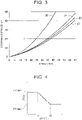
- FIG. 3 is a graph defining relationships between a speed and a stopping distance for four typical types of target (automobile, motorcycle, motorized bicycle, and bicycle) that may be obstructive targets.
- FIG. 3 is based on data from the Institute for Traffic Accident Research and Data Analysis. Continuous lines 30 to 33 represent behaviors of the bicycle, the motorized bicycle, the motorcycle, and the automobile, respectively.
- the stopping distance is a distance traveled by the target during a time from a timing when a driver of the target senses danger (for example, when the driver recognizes a drop-off action of the occupant of the vehicle) to a timing when the target stops after the driver starts braking.
- the stopping distance is the sum of a free running distance and a braking distance.
- the slope of a tangent to the continuous line at any speed represents an avoidance limit time of the target associated with the continuous line.
- an avoidance limit time when the bicycle is traveling at an average speed (for example, 10 to 20 [km/h]) is longer than an avoidance limit time of a vehicle other than the bicycle at any speed.
- a stopping distance when the bicycle is traveling at the average speed is longer than a stopping distance of the vehicle other than the bicycle at any speed. Therefore, the TTCth is generally determined based on the avoidance limit time of the bicycle (that is, the avoidance limit time having the largest value).
- the drop-off assist control for the vehicle other than the bicycle is started at a significantly early timing. Therefore, a problem may arise in that unnecessary drop-off assist control is executed. Due to the current performance of the radar sensor 12 (limit in terms of the detection accuracy for a distant target), a deviation is likely to occur in a result of calculation of a moving direction of the target (that is, the vehicle other than the bicycle) located in a distant region rearward of the host vehicle. As a result, a problem may arise in that a target that does not actually correspond to the obstructive target is erroneously detected as the obstructive target and unnecessary drop-off assist control is executed.
- a TTCth having a value smaller than the "TTCth determined based on the avoidance limit time of the bicycle” may be set for the vehicle other than the bicycle.
- the radar sensor 12 cannot discriminate the type of the target.
- the speed distribution of bicycles traveling on roads is 1% for 5 [km/h] or lower, 54% for 15 [km/h] or lower, 42% for 25 [km/h] or lower, and 3% for over 25 [km/h]. That is, the bicycles traveling at the speeds of 25 [km/h] or lower are in the majority accounting for 97%, and there are few bicycles traveling at the speeds over 25 [km/h].
- FIG. 4 is a map defining a relationship between a speed v of the target and the TTCth.
- the map is prestored in the ROM of the ECU 10.
- the TTCth is maintained to be a first time threshold TTCth1 when the speed v of the target is equal to or lower than a first speed v1 (v ⁇ v1).
- the TTCth is maintained to be a second time threshold TTCth2 ( ⁇ TTCth 1) when the speed v of the target is higher than a second speed v2 (> v1) (v2 ⁇ v).
- the TTCth linearly decreases from TTCth1 to TTCth2 when the speed v of the target is higher than the first speed v1 and equal to or lower than the second speed v2 (v1 ⁇ v ⁇ v2).
- the ECU 10 calculates the speed of the target
- the ECU 10 reads a value corresponding to the speed of the target by referring to the map shown in FIG. 4 , and sets the value as the TTCth.
- the ECU 10 calculates the speed of the target based on a vehicle speed acquired from the vehicle speed sensor 11 and a relative speed of the target included in the target information.
- the first speed v1 is set to "such a value that a possibility that the target is a bicycle is very low when the target is traveling at a speed satisfying v1 ⁇ v".
- the first speed v1 is set to a "value indicating a very small ratio of bicycles traveling on roads at speeds higher than v1".
- the first speed v1 is set to a value indicating that the ratio of bicycles traveling on roads at speeds higher than v1 is 3%. That is, the first speed v1 is set to 25 [km/h].
- the TTCth1 is set based on the avoidance limit time when the bicycle is traveling at the average speed (for example, 10 to 20 [km/h]) (that is, the slope of a tangent to the continuous line 30 at the average speed of the bicycle in FIG. 3 ).
- the average speed of the bicycle corresponds to an example of a "first speed range".
- the first speed range may be a range of a speed at which the bicycle is high likely to traveling.
- the TTCth1 may be set based on an avoidance limit time in another speed range of the bicycle.
- the TTCth2 is set based on an avoidance limit time when vehicles other than the bicycle are traveling at an average speed (for example, 30 to 60 [km/h]) (that is, the slopes of tangents to the continuous lines 31 to 33 at the average speed of the vehicles other than the bicycle in FIG. 3 ).
- the average speed of the vehicles other than the bicycle corresponds to an example of a "second speed range".
- the second speed range may be a range of a speed at which the vehicles other than the bicycle are high likely to traveling.
- the second speed v2 is introduced to suppress instability of the operation of the drop-off assist control due to an abrupt change in the TTCth.
- the second speed v2 is introduced and the TTCth gradually changes (gradually decreases) when v1 ⁇ v ⁇ v2 holds.
- the second speed v2 can be set to any value larger than the first speed v1.
- the second speed v2 can be set to any value selected from the average speed of the vehicles other than the bicycle (for example, 30 to 60 [km/h]).
- TTCth is set to TTCth2.
- the TTCth is changed to a smaller value when there is a very strong possibility that the target is a vehicle other than the bicycle than when there is no such possibility.
- the start timing of the drop-off assist control can be delayed to an appropriate timing when the target is the vehicle other than the bicycle. As a result, it is possible to suppress both the unnecessary operation caused by the significantly early start timing of the control and the unnecessary operation caused by the performance of the radar sensor 12.
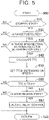
- the CPU of the ECU 10 repeats a routine shown in a flowchart of FIG. 5 every time a predetermined period elapses during a period in which electric power is supplied to the ECU 10 (described later).
- Step 510 determines whether the host vehicle is in the stopped state based on the vehicle speed acquired from the vehicle speed sensor 11 (Condition 1).
- the CPU determines "No” in Step 510 (that is, determines that Condition 1 is not satisfied (the alert condition is not satisfied)), and proceeds to Step 595 to temporarily terminate this routine.
- the CPU determines "Yes” in Step 510 (that is, determines that Condition 1 is satisfied), and proceeds to Step 520.
- Step 520 the CPU determines whether a target is detected based on the target information acquired from the radar sensor 12. When the target is not detected, the CPU determines "No” in Step 520 and proceeds to Step 595 to temporarily terminate this routine. When the target is detected, the CPU determines "Yes” in Step 520 and proceeds to Step 530.
- Step 530 the CPU calculates the speed vector A of the detected target based on the target information, and determines whether the extension line of the speed vector A intersects the right or left intersection determination line LR or LL. When there is no intersection, the CPU determines "No” in Step 530 and proceeds to Step 595 to temporarily terminate this routine. When there is intersection, the CPU determines "Yes” in Step 530 and proceeds to Step 540.
- Step 540 the CPU calculates the TTC for the detected target and proceeds to Step 550.
- Step 550 the CPU calculates the speed v of the detected target, reads a value corresponding to the speed v by referring to the map shown in FIG. 4 , and sets the value as the TTCth. That is, the CPU sets the TTCth depending on the speed v of the target. Then, the CPU proceeds to Step 560.
- Step 560 the CPU determines whether TTC ⁇ TTCth holds for the detected target (Condition 2).
- the CPU determines "No” in Step 560 (that is, determines that Condition 2 is not satisfied (the alert condition is not satisfied)), and proceeds to Step 595 to temporarily terminate this routine.
- TTC ⁇ TTCth holds, the CPU determines "Yes” in Step 560 (that is, determines that Condition 2 is satisfied (the target is the obstructive target)), and proceeds to Step 570.
- Step 570 the CPU determines whether the door (door on a side where the obstructive target is detected) is in the open state based on a signal acquired from the door open/close sensor 13.
- the CPU determines "No” in Step 570 (that is, determines that Condition 3 is not satisfied (the alert condition is not satisfied)), and proceeds to Step 595 to temporarily terminate this routine.
- the CPU determines "Yes” in Step 570 (that is, determines that Condition 3 is satisfied (the alert condition is satisfied)), and proceeds to Step 580 to execute the alert control (Processes 1 to 4). Then, the CPU proceeds to Step 595 to temporarily terminate this routine.
- the power supply to the ECU 10 is continued until a predetermined condition is satisfied even after an ignition switch is turned OFF.
- this condition may be satisfied when the doors are locked or when a predetermined stop period has elapsed after the host vehicle is stopped. According to this configuration, it is possible to reduce the possibility that the alert control is not executed in a situation in which the alert control is required, thereby executing the alert control more appropriately.
- the map defining the relationship between the speed v of the target and the TTCth is not limited to the map in the structure shown in FIG. 4 .
- the map is structured such that, when the speed v of the target is higher than the first speed v1, the TTCth is set to a smaller value as compared with the case where the speed v of the target is equal to or lower than the first speed v1, the threshold such as the second speed v2 need not be set.
- the alert control is executed as the drop-off assist control, but the type of the drop-off assist control is not limited to the alert control.
- door opening limitation control of the drop-off assist device to limit the degree of door opening or door lock control of the drop-off assist device to lock the door may be executed as the drop-off assist control.
- the door opening limitation control or the door lock control may be executed as the drop-off assist control in addition to the alert control.
- Condition 2 is satisfied when TTC ⁇ TTCth holds for the target, but the requirement for satisfaction of Condition 2 is not limited to this requirement.
- Condition 2 may be satisfied when the state where TTC of the target is equal to or smaller than TTCth continues for a predetermined duration.
- Condition 3 may be satisfied when the door on the side where the obstructive target is detected is changed from the closed state to the open state.
- Condition 3 may be satisfied when an occupant's action for operating a door operation unit (typically, an inner lever of the door) is detected based on image data obtained by a camera mounted on the vehicle (camera capable of imaging the occupant in the vehicle).
- the alert condition is satisfied when Conditions 1 to 3 are all satisfied, but the requirement for satisfaction of the alert condition is not limited to this requirement.
- the alert condition need not include Condition 3, and may be satisfied when Conditions 1 and 2 are satisfied.
- the alert control may be executed regardless of whether the occupant has a drop-off intention.
- the alert control may be executed in two stages.
- the alert control includes two types of control, that is, normal alert control and minor alert control (control at a lower assist level than that of the normal alert control).
- the minor alert control is, for example, control for executing Process 1.
- the normal alert control is, for example, control for executing at least one of Processes 2 to 4 in addition to Process 1.
- the minor alert control is executed when Conditions 1 and 2 are satisfied (that is, when the obstructive target is detected while the vehicle is stopped but the door is in the closed state).
- the normal alert control is executed when Condition 3 is further satisfied in addition to Conditions 1 and 2 (that is, when the obstructive target is detected while the vehicle is stopped and the door is in the open state).
- the drop-off assist device When the door is in the closed state, the drop-off assist device cannot determine whether the occupant is attempting to drop off from the door. In other words, there may be both a possibility that the occupant has a drop-off intention but the door is not open at the current time, and a possibility that the occupant does not have the drop-off intention and the door remains in the closed state. Therefore, when the door is in the closed state, the drop-off assist device executes the minor alert control to "notify in advance the occupant having the drop-off intention about the presence of the obstructive target" and "prevent the occupant having no drop-off intention from suffering discomfort caused by executing the normal alert control".
- the door opening limitation control or the door lock control may be executed as the drop-off assist control in place of the normal alert control.
- the door opening limitation control or the door lock control may be executed as the drop-off assist control in addition to the normal alert control.
Landscapes
- Engineering & Computer Science (AREA)
- Mechanical Engineering (AREA)
- Automation & Control Theory (AREA)
- Transportation (AREA)
- Radar, Positioning & Navigation (AREA)
- Remote Sensing (AREA)
- Human Computer Interaction (AREA)
- Physics & Mathematics (AREA)
- Electromagnetism (AREA)
- Computer Networks & Wireless Communication (AREA)
- General Physics & Mathematics (AREA)
- Traffic Control Systems (AREA)
Abstract
Description
- The present invention relates to a drop-off assist device, a drop-off assist method, and a non-transitory storage medium.
- There is a known a drop-off assist device capable of executing drop-off assist control to assist safe drop-off of an occupant of a vehicle (typically, an automobile). For example, the drop-off assist device executes the drop-off assist control when an occupant's drop-off intention (typically, an occupant's door opening operation) is detected in a case where an obstructive target that may hinder the occupant's safe drop-off (in other words, pass by the side of the vehicle) is detected while the vehicle is stopped (see
Japanese Unexamined Patent Application Publication No. 2007-138457 JP 2007-138457 A - The drop-off assist device detects the obstructive target as follows. The drop-off assist device includes a target information acquisition device (for example, a radar sensor) that can detect a target present in a region rearward of the host vehicle and acquire information about the target as target information. The drop-off assist device calculates, based on the target information acquired from the target information acquisition device, a predicted time required for the target to come into contact with or to come into close proximity to the host vehicle (time to collision; hereinafter referred to also as "TTC"). When the TTC is equal to or smaller than a preset time threshold TTCth, the drop-off assist device determines that the target may hinder the occupant's safe drop-off, and detects the target as the obstructive target.
- The TTCth is determined based on a stopping time of the target. The stopping time is a time from a timing when a driver of the target senses danger (for example, when the driver recognizes a drop-off action of the occupant of the vehicle) to a timing when the target stops after the driver starts braking (starts to apply a brake). In other words, the stopping time is the sum of a free running time and a braking time. When the TTC of a certain target is larger than the stopping time of the target, there is a small possibility that the target will hinder the occupant's safe drop-off. Therefore, the stopping time may be a limit value of a time within which the target can avoid contact with or close proximity to the host vehicle. Thus, the stopping time is hereinafter referred to also as "avoidance limit time". By determining the TTCth based on the avoidance limit time (stopping time), unnecessary drop-off assist control is not executed when the target can avoid contact with or close proximity to the host vehicle by braking.
- The avoidance limit time varies depending on the type of the target. Among typical vehicles that may be obstructive targets, such as an automobile, a motorcycle, a motorized bicycle, and a bicycle, the bicycle has the longest avoidance limit time. There is no much difference in the avoidance limit time among the other vehicles. Therefore, the TTCth is generally determined based on the avoidance limit time of the bicycle that is the maximum value.
- According to this configuration, the drop-off assist control can be executed at an appropriate timing in a case where the target is a bicycle. In a case where the target is any other vehicle (that is, an automobile, a motorcycle, or a motorized bicycle), however, a value significantly larger than the avoidance limit time of this vehicle is set as the TTCth. Therefore, when the TTC of this vehicle is equal to or smaller than the TTCth though the TTC is sufficiently larger than the avoidance limit time (in other words, when the driver senses danger at this timing and starts braking, the vehicle may sufficiently avoid contact with or close proximity to the host vehicle), the vehicle is detected as the obstructive target and the drop-off assist control is executed. In the configuration in which the TTCth is determined based on the avoidance limit time of the bicycle, the drop-off assist control is executed for the vehicles other than the bicycle at a timing significantly earlier than the timing when the drop-off assist control is actually required. Therefore, a problem may arise in that unnecessary drop-off assist control is executed.
- When the TTCth is set to a value larger than the avoidance limit time of a vehicle other than the bicycle, the problem of unnecessary execution of the drop-off assist control may arise for another reason. As described above, the drop-off assist device calculates the TTC of the target. This calculation process is performed only for a target that may pass by the side of the host vehicle in the future among the targets detected by the target information acquisition device. Specifically, the drop-off assist device calculates moving directions of the detected targets based on the target information. When an extension line in the moving direction of any target passes by the side of the host vehicle, the TTC of this target is calculated.
- The current performance of the target information acquisition device has a limit in terms of the detection accuracy for a distant target. Therefore, the target information of the distant target is likely to include a deviation. As a result, a deviation is likely to occur in the result of calculation of the moving direction of the target. In general, vehicles other than the bicycle travel at speeds higher than that of the bicycle. Therefore, the detection of the vehicle other than the bicycle by the target information acquisition device needs to be started when the vehicle is located far behind the host vehicle. In this case, a deviation is likely to occur in the result of calculation of the moving direction of the vehicle. As a result, the extension line in the moving direction may pass by the side of the host vehicle and the TTC may be calculated even though the vehicle is not actually the target of TTC calculation (that is, there is no possibility of passing by the side of the host vehicle in the future). In such a case, there is a strong possibility that TTC ≤ TTCth easily holds when the TTCth is set to a relatively large value. Therefore, there is a strong possibility that a vehicle other than the bicycle is erroneously detected as the obstructive target. Thus, a problem may arise in that unnecessary drop-off assist control is executed.
- The present invention provides a drop-off assist device capable of suppressing unnecessary execution of drop-off assist control.
- A drop-off assist device according to a first aspect of the present invention includes a target information acquisition sensor configured to detect a target present in a region rearward of a host vehicle, and acquire information about the detected target as target information; and an electronic control unit configured to, while the host vehicle is stopped, calculate, based on the target information, a predicted time required for the target to come into contact with or to come into close proximity to the host vehicle, and execute drop-off assist control for assisting drop-off of an occupant of the host vehicle when the predicted time is equal to or smaller than a predetermined time threshold, set the predetermined time threshold to a predetermined first time threshold when a speed of the detected target is equal to or lower than a predetermined first speed, and set the predetermined time threshold to a value smaller than the predetermined first time threshold when the speed of the detected target is higher than the predetermined first speed.
- In the present invention, when the speed of the target detected by the target information acquisition device (sensor) is equal to or lower than the first speed, the time threshold (time threshold of the predicted time to be used for determining whether the drop-off assist control needs to be executed) is set to the first time threshold. When the speed of the target is higher than the first speed, the time threshold is set to the value smaller than the first time threshold.
In general, an avoidance limit time (stopping time) of a vehicle other than a bicycle (typically, an automobile, a motorcycle, or a motorized bicycle) is shorter than an avoidance limit time of the bicycle. When the speed of a certain target is higher than a predetermined speed threshold, there is a very small possibility that the target is the bicycle. By setting the first speed to an appropriate value (for example, the above speed threshold), the time threshold in a case where the target is the vehicle other than the bicycle can be set to the value smaller than the time threshold in a case where the target is the bicycle. According to this configuration, the start timing of the drop-off assist control can be delayed to an appropriate timing when the target is the vehicle other than the bicycle, as compared with a configuration in which the time threshold is uniformly determined based on the avoidance limit time of the bicycle. As a result, it is possible to suppress both an unnecessary operation caused by a significantly early start timing of the control and an unnecessary operation caused by the performance of the target information acquisition device (sensor). - In the aspect described above, the predetermined first speed may be set based on a speed distribution of a bicycle traveling on a road; and the predetermined first time threshold may be set based on an avoidance limit time of the bicycle at a speed within a predetermined first speed range. The avoidance limit time is a limit value of a time within which the target is capable of avoiding the contact with or the close proximity to the host vehicle.
- According to this configuration, the first speed and the first time threshold can be set to appropriate values. The first speed range is, for example, an average speed range when the bicycle travels on the road.
- In the aspect described above, the electronic control unit may be configured to set the predetermined time threshold to a predetermined second time threshold smaller than the predetermined first time threshold when the speed of the detected target is higher than a predetermined second speed higher than the predetermined first speed.
- According to this configuration, by setting the second speed and the second time threshold to appropriate values, it is possible to more reliably suppress the unnecessary execution of the drop-off assist control in the case where the target is the vehicle other than the bicycle.
- In the aspect described above, the predetermined second speed may be set based on a speed distribution of the target other than a bicycle traveling on a road; and the predetermined second time threshold may be set based on an avoidance limit time of the target other than the bicycle at a speed within a predetermined second speed range. The avoidance limit time is a limit value of a time within which the target is capable of avoiding the contact with or the close proximity to the host vehicle.
- According to this configuration, the second speed and the second time threshold can be set to appropriate values. The second speed range is, for example, an average speed range when the vehicle other than the bicycle travels on the road.
- In the aspect described above, the electronic control unit may be configured to, when the electronic control unit determines that the occupant intends to drop off and while the host vehicle is stopped, calculate the predicted time, and execute the drop-off assist control when the predicted time is equal to or smaller than the predetermined time threshold.
- In the aspect described above, the drop-off assist control may be control of the electronic control unit to generate an alert.
- In the aspect described above, the drop-off assist control may be control of the electronic control unit to limit a degree of door opening.
- In the aspect described above, the drop-off assist control may be control of the electronic control unit to lock a door.
- In the aspect described above, the electronic control unit may be configured to execute the drop-off assist control when the predicted time is equal to or smaller than the predetermined time threshold continuously for a predetermined period.
- A drop-off assist method according to a second aspect of the present invention includes detecting a target present in a region rearward of a host vehicle; acquiring information about the detected target as target information; and while the host vehicle is stopped, i) calculating, based on the target information, a predicted time required for the target to come into contact with or to come into close proximity to the host vehicle; ii) setting a predetermined time threshold to a predetermined first time threshold when a speed of the detected target is equal to or lower than a predetermined first speed; iii) setting the predetermined time threshold to a value smaller than the predetermined first time threshold when the speed of the detected target is higher than the predetermined first speed; and iv) executing drop-off assist control for assisting drop-off of an occupant of the host vehicle when the predicted time is equal to or smaller than the predetermined time threshold.
- A non-transitory storage medium according to a third aspect of the present invention stores instructions that are executable by one or more processors and that cause the one or more processors to perform functions. The functions include detecting a target present in a region rearward of a host vehicle; acquiring information about the detected target as target information; and while the host vehicle is stopped, i) calculating, based on the target information, a predicted time required for the target to come into contact with or to come into close proximity to the host vehicle; ii) setting a predetermined time threshold to a predetermined first time threshold when a speed of the detected target is equal to or lower than a predetermined first speed; iii) setting the predetermined time threshold to a value smaller than the predetermined first time threshold when the speed of the detected target is higher than the predetermined first speed; and iv) executing drop-off assist control for assisting drop-off of an occupant of the host vehicle when the predicted time is equal to or smaller than the predetermined time threshold.
- Features, advantages, and technical and industrial significance of exemplary embodiments of the invention will be described below with reference to the accompanying drawings, in which like signs denote like elements, and wherein:
-
FIG. 1 is a schematic configuration diagram of a drop-off assist device according to an embodiment of the present invention (present embodiment device); -
FIG. 2 is a diagram showing a three-dimensional object detection range of a radar sensor in the present embodiment device, and illustrating a method for calculating a TTC of a target detected by the radar sensor; -
FIG. 3 is a graph defining relationships between a speed and a stopping distance for four types of vehicle, and illustrating an avoidance limit time; -
FIG. 4 is a map defining a relationship between a speed v of a target and a time threshold TTCth; and -
FIG. 5 is a flowchart showing a routine to be executed by a central processing unit (CPU) of a drop-off assist electronic control unit (ECU) of the present embodiment device. - Hereinafter, a drop-off assist device according to an embodiment of the present invention (hereinafter referred to also as "present embodiment device") will be described with reference to the drawings. As shown in
FIG. 1 , the present embodiment device includes a drop-off assistECU 10 and avehicle speed sensor 11, aradar sensor 12, door open/close sensors 13,side mirror indicators 20, aninstrument panel 21, abuzzer 22, and aloudspeaker 23 that are connected to the drop-off assistECU 10. The drop-off assistECU 10 includes a microcomputer as a main component. The ECU is an abbreviation for "electronic control unit". The microcomputer includes a CPU, a read-only memory (ROM), a random-access memory (RAM), an interface (I/F), and the like, and the CPU implements various functions by executing instructions (programs or routines) stored in the ROM. The vehicle including the present embodiment device is hereinafter referred to as "host vehicle". - The drop-off assist
ECU 10 acquires signals generated or output by thesensors 11 to 13 every time a predetermined time elapses, and controls the elements (devices) 20 to 23 based on the acquired signals. The drop-off assistECU 10 is hereinafter referred to simply as "ECU 10" as well. - The
vehicle speed sensor 11 generates a signal based on a traveling speed of the host vehicle (hereinafter referred to as "vehicle speed"). TheECU 10 acquires the signal generated by thevehicle speed sensor 11 and calculates the vehicle speed based on the signal. When the vehicle speed is zero, theECU 10 determines that the host vehicle is in a stopped state (hereinafter referred to also as "while the vehicle is stopped"). - The radar sensor 12 (target information acquisition device) has a function of acquiring information about a three-dimensional object (target) present in a region rearward (a region behind the vehicle or the sides of a region behind the vehicle) of the host vehicle. The three-dimensional object is a moving object such as a vehicle or a pedestrian. The vehicle includes an automobile, a motorcycle, a motorized bicycle, and a bicycle.
- As shown in
FIG. 2 , theradar sensor 12 includes aleft radar sensor 12L provided at a left corner of a rear bumper (not shown in drawings) of a host vehicle V, and aright radar sensor 12R provided at a right corner of the rear bumper of the host vehicle V. Theradar sensor 12 irradiates the surroundings of the host vehicle with radio waves in a millimeter wave band. Specifically, theleft radar sensor 12L radiates the radio wave in a range including a left region RL on a left rear side of the host vehicle, and theright radar sensor 12R radiates the radio wave in a range including a right region RR on a right rear side of the host vehicle. Both the right region RR and the left region RL are shaped to be elongated outward and inward in a vehicle width direction as the distance increases rearward from the host vehicle V. InFIG. 2 , the ratios of the regions RR and RL to the host vehicle V are changed for convenience. - When the three-dimensional object is within the radiation ranges of the radio waves, the
radar sensor 12 receives the reflected wave from the three-dimensional object. Theradar sensor 12 calculates the presence or absence of the three-dimensional object and a relative relationship between the host vehicle and the three-dimensional object (distance from the host vehicle to the three-dimensional object, direction of the three-dimensional object with respect to the host vehicle, and relative speed of the three-dimensional object to the host vehicle) based on, for example, a radiation timing and a reception timing of the radio wave. In other words, theradar sensor 12 detects the three-dimensional object present in a region rearward of the host vehicle. The three-dimensional object detected by the radar sensor 12 (that is, the three-dimensional object present in the region RR or RL) is hereinafter referred to also as "target". Theradar sensor 12 outputs these pieces of information about the target to theECU 10 as target information. - As long as the
radar sensor 12 can radiate the radio wave in a range including a region corresponding to the regions RR and RL, the number ofradar sensors 12 is not limited to two but may be one, three, or more. In a case of oneradar sensor 12, thesensor 12 may be mounted, for example, substantially at the center of the rear bumper of the host vehicle V.
The sensor that acquires the target information is not limited to theradar sensor 12. For example, a laser radar sensor, an ultrasonic sensor, and/or a camera sensor may be used in place of or in addition to theradar sensor 12. Alternatively, a sensor to be used for blind spot monitor control may be used as theradar sensor 12. The blind spot monitor control is control for alerting a driver of the host vehicle in response to detection of a vehicle approaching the host vehicle from behind (in particular, a vehicle present in a region where the vehicle is difficult to view on a side mirror). - The description will be continued returning to
FIG. 1 . The door open/close sensors 13 are provided for a plurality of doors (more specifically, side doors) of the host vehicle, respectively. The door open/close sensor 13 detects an open or closed state of the door. When the door open/close sensor 13 detects that the door is in the open state, the door open/close sensor 13 generates, during a period in which the open state is detected, an open signal indicating that the door is in the open state. When the door open/close sensor 13 detects that the door is in the closed state, the door open/close sensor 13 generates, during a time in which the closed state is detected, a close signal indicating that the door is in the closed state. TheECU 10 detects which of the open signal and the close signal is generated by the door open/close sensor 13, and detects whether the door associated with the door open/close sensor 13 is in the open state or the closed state based on the detection result. - The
side mirror indicators 20 are provided at predetermined positions on the right and left side mirrors of the host vehicle, and can be turned ON or OFF independently of each other. Theinstrument panel 21 is provided in front of a driver's seat of the host vehicle (at a position where theinstrument panel 21 is visible to the driver). Thebuzzer 22 is built in theinstrument panel 21. Theloudspeaker 23 is a component of a navigation system (not shown) and is provided near a touch panel display (not shown). Details of Operation - Next, details of operation of the
ECU 10 will be described. In the present embodiment, theECU 10 executes alert control (described later) as drop-off assist control. The alert control is executed when an alert condition is satisfied. The alert condition is satisfied when Conditions 1 to 3 are all satisfied. - (Condition 1) The host vehicle is in the stopped state.
- (Condition 2) An obstructive target is detected.
- (Condition 3) The door of the host vehicle is in the open state.
- First, Condition 1 will be described. When the vehicle speed acquired from the
vehicle speed sensor 11 is zero, theECU 10 determines that Condition 1 is satisfied. - Next, Condition 2 will be described. The obstructive target is a target that may hinder safe drop-off of the occupant of the host vehicle (in other words, pass by the side of the host vehicle), and is typically a moving object approaching the host vehicle from a region rearward of it. The
ECU 10 detects the obstructive target as follows. That is, when theECU 10 determines that a target is present in the right region RR or the left region RL based on the target information acquired from theradar sensor 12, theECU 10 calculates a predicted time required for the target to come into contact with or to come into close proximity to the host vehicle (TTC). When the TTC is equal to or smaller than a predetermined time threshold TTCth, theECU 10 detects the target as the obstructive target and determines that Condition 2 is satisfied. - Further details will be described with reference to
FIG. 2. FIG. 2 shows a situation in which another vehicle Vt (in this example, an automobile) is approaching the host vehicle V from behind. As shown inFIG. 2 , when the host vehicle V is in the stopped state (that is, Condition 1 is satisfied), theECU 10 sets an xy coordinate system with its origin at the center between the right and left corners of the rear bumper of the host vehicle V. An x-axis extends in a front-rear direction of the host vehicle V, and a y-axis extends in the vehicle width direction (lateral direction) of the host vehicle V. That is, the y-axis may be an axis that passes through the right and left corners of the rear bumper. - The
ECU 10 sets an intersection determination line L on the host vehicle V when the host vehicle V is in the stopped state. The intersection determination line L is an imaginary line set for calculating the TTC, and includes a right intersection determination line LR and a left intersection determination line LL. The left intersection determination line LL extends on the y-axis in a negative y-axis direction (outward in the vehicle width direction) from the left corner of the rear bumper, and the right intersection determination line LR extends on the y-axis in a positive y-axis direction (outward in the vehicle width direction) from the right corner of the rear bumper. The lengths of the right and left intersection determination lines LR and LL are the same (for example, about 1.3 [m]). In the present embodiment, the lengths of the right and left intersection determination lines LR and LL are substantially equal to the lengths of the regions RR and RL in the y-axis direction from the right and left corners of the rear bumper. The lengths of the right and left intersection determination lines LR and LL are preset through experiment or simulation so that "when the target passes through any position on the determination line LR or LL while the occupant of the host vehicle V is dropping off, the target may come into contact with the door or the occupant of the host vehicle V". - When the host vehicle V is in the stopped state, the
ECU 10 calculates a speed vector A of the target (in the example ofFIG. 2 , the other vehicle Vt) based on the target information, and sets starting point of the speed vector A to a near portion np of the target. The near portion np is a portion of the front end of the target that is closest to the host vehicle V in the y-axis direction. The speed vector A can be derived by, for example, differentiating the position (distance and direction) of the target with respect to a time. That is, the speed vector A represents a moving direction of the target at a current time. - When an extension line of the speed vector A of the target intersects the right or left intersection determination line LR or LL (in other words, an intersection P of the extension line and the y-axis is on the intersection determination line L), the
ECU 10 calculates, as the TTC, a "predicted time required for the target to intersect the intersection determination line L (in other words, a predicted time required for the target to reach the intersection P of the extension line of the speed vector A of the target and the intersection determination line L)"). The TTC is calculated by using the target information, and can be calculated, for example, by dividing a "distance from the near portion np to the intersection P" by a "current speed of the target". - When the TTC in a case where the target will intersect the left intersection determination line LL in the future is equal to or smaller than the TTCth, the
ECU 10 determines that the target may hinder the occupant from safely dropping off from the left door, and detects the target as an obstructive target for the left door.
When the TTC in a case where the target will intersect the right intersection determination line LR in the future is equal to or smaller than the TTCth, theECU 10 determines that the target may hinder the occupant from safely dropping off from the right door, and detects the target as an obstructive target for the right door.
In these cases, theECU 10 determines that Condition 2 is satisfied. - When the target will intersect the right or left intersection determination line LR or LL in the future but the TTC is larger than the TTCth, the
ECU 10 determines that the target (currently) has no possibility of hindering the occupant's safe drop-off, and does not detect the target as the obstructive target.
When the extension line of the speed vector A of the target will intersect neither of the right and left intersection determination lines LR and LL (in other words, the intersection P of the extension line and the y-axis is not on the intersection determination line L), the TTC is not calculated. Therefore, theECU 10 does not detect the target as the obstructive target. In these cases, theECU 10 determines that Condition 2 is not satisfied. - In the example of
FIG. 2 , the intersection P is on the right intersection determination line LR (that is, the other vehicle Vt will intersect the right intersection determination line LR in the future). Therefore, theECU 10 calculates the TTC for the other vehicle Vt. TheECU 10 detects the other vehicle Vt as the obstructive target for the right door when the TTC is equal to or smaller than the TTCth, and does not detect the other vehicle Vt as the obstructive target when the TTC is larger than the TTCth. - Next,
Condition 3 will be described. When theECU 10 determines that the door on a side where the obstructive target is detected is in the open state based on the signal acquired from the door open/close sensor 13, theECU 10 determines thatCondition 3 is satisfied (in other words, the occupant has a drop-off intention). - Next, the alert control will be described. When the alert condition is satisfied, the
ECU 10 performs Processes 1 to 4 as the alert control. - (Process 1) A process of turning ON the
side mirror indicator 20 on the side where the obstructive target is detected. - (Process 2) A process of displaying a predetermined mark (for example, a mark indicating the right rear side or the left rear side from which the obstructive target is approaching) on the
instrument panel 21. - (Process 3) A process of sounding the
buzzer 22. - (Process 4) A process of causing the
loudspeaker 23 to issue a predetermined message (for example, a message "Please be careful of an approaching vehicle."). - In general, one type of constant is used for the TTCth. This constant can be determined based on an avoidance limit time (stopping time) of the target. According to this determination method, however, unnecessary alert control may be executed for a specific type of target. Details will be described with reference to
FIG. 3. FIG. 3 is a graph defining relationships between a speed and a stopping distance for four typical types of target (automobile, motorcycle, motorized bicycle, and bicycle) that may be obstructive targets.FIG. 3 is based on data from the Institute for Traffic Accident Research and Data Analysis.Continuous lines 30 to 33 represent behaviors of the bicycle, the motorized bicycle, the motorcycle, and the automobile, respectively. The stopping distance is a distance traveled by the target during a time from a timing when a driver of the target senses danger (for example, when the driver recognizes a drop-off action of the occupant of the vehicle) to a timing when the target stops after the driver starts braking. In other words, the stopping distance is the sum of a free running distance and a braking distance. - The slope of a tangent to the continuous line at any speed (that is, a speed derivative of the stopping distance) represents an avoidance limit time of the target associated with the continuous line. According to the graph of
FIG. 3 , an avoidance limit time when the bicycle is traveling at an average speed (for example, 10 to 20 [km/h]) is longer than an avoidance limit time of a vehicle other than the bicycle at any speed. In other words, a stopping distance when the bicycle is traveling at the average speed is longer than a stopping distance of the vehicle other than the bicycle at any speed. Therefore, the TTCth is generally determined based on the avoidance limit time of the bicycle (that is, the avoidance limit time having the largest value). - According to this determination method, however, the drop-off assist control for the vehicle other than the bicycle is started at a significantly early timing. Therefore, a problem may arise in that unnecessary drop-off assist control is executed. Due to the current performance of the radar sensor 12 (limit in terms of the detection accuracy for a distant target), a deviation is likely to occur in a result of calculation of a moving direction of the target (that is, the vehicle other than the bicycle) located in a distant region rearward of the host vehicle. As a result, a problem may arise in that a target that does not actually correspond to the obstructive target is erroneously detected as the obstructive target and unnecessary drop-off assist control is executed.
- To suppress the unnecessary execution of the drop-off assist control described above, a TTCth having a value smaller than the "TTCth determined based on the avoidance limit time of the bicycle" may be set for the vehicle other than the bicycle. In the present embodiment, however, the
radar sensor 12 cannot discriminate the type of the target. It is known that the speed distribution of bicycles traveling on roads is 1% for 5 [km/h] or lower, 54% for 15 [km/h] or lower, 42% for 25 [km/h] or lower, and 3% for over 25 [km/h]. That is, the bicycles traveling at the speeds of 25 [km/h] or lower are in the majority accounting for 97%, and there are few bicycles traveling at the speeds over 25 [km/h]. This means that, when the speed of a certain target is over 25 [km/h], there is a very small possibility that the target is a bicycle (in other words, there is a very strong possibility that the target is a vehicle other than a bicycle). - From the above, the
ECU 10 of the present embodiment can change the TTCth depending on the speed of the target. Details will be described with reference toFIG. 4. FIG. 4 is a map defining a relationship between a speed v of the target and the TTCth. The map is prestored in the ROM of theECU 10. As shown inFIG. 4 , the TTCth is maintained to be a first time threshold TTCth1 when the speed v of the target is equal to or lower than a first speed v1 (v ≤ v1). The TTCth is maintained to be a second time threshold TTCth2 (< TTCth 1) when the speed v of the target is higher than a second speed v2 (> v1) (v2 < v). The TTCth linearly decreases from TTCth1 to TTCth2 when the speed v of the target is higher than the first speed v1 and equal to or lower than the second speed v2 (v1 < v ≤ v2). When theECU 10 calculates the speed of the target, theECU 10 reads a value corresponding to the speed of the target by referring to the map shown inFIG. 4 , and sets the value as the TTCth. TheECU 10 calculates the speed of the target based on a vehicle speed acquired from thevehicle speed sensor 11 and a relative speed of the target included in the target information. - The first speed v1 is set to "such a value that a possibility that the target is a bicycle is very low when the target is traveling at a speed satisfying v1 < v". In other words, the first speed v1 is set to a "value indicating a very small ratio of bicycles traveling on roads at speeds higher than v1". In the present embodiment, the first speed v1 is set to a value indicating that the ratio of bicycles traveling on roads at speeds higher than v1 is 3%. That is, the first speed v1 is set to 25 [km/h]. The TTCth1 is set based on the avoidance limit time when the bicycle is traveling at the average speed (for example, 10 to 20 [km/h]) (that is, the slope of a tangent to the
continuous line 30 at the average speed of the bicycle inFIG. 3 ). The average speed of the bicycle corresponds to an example of a "first speed range". The first speed range may be a range of a speed at which the bicycle is high likely to traveling. The TTCth1 may be set based on an avoidance limit time in another speed range of the bicycle. - The TTCth2 is set based on an avoidance limit time when vehicles other than the bicycle are traveling at an average speed (for example, 30 to 60 [km/h]) (that is, the slopes of tangents to the
continuous lines 31 to 33 at the average speed of the vehicles other than the bicycle inFIG. 3 ). The average speed of the vehicles other than the bicycle corresponds to an example of a "second speed range". The second speed range may be a range of a speed at which the vehicles other than the bicycle are high likely to traveling. The second speed v2 is introduced to suppress instability of the operation of the drop-off assist control due to an abrupt change in the TTCth. That is, in a configuration in which the TTCth is set to TTCth1 when v ≤ v1 holds and the TTCth is set to TTCth2 when v1 < v holds, the TTCth abruptly changes because v changes around v1 and the drop-off assist control is repeatedly stopped and executed, that is, the operation of the drop-off assist control is instable. Therefore, the second speed v2 is introduced and the TTCth gradually changes (gradually decreases) when v1 < v ≤ v2 holds. Thus, the second speed v2 can be set to any value larger than the first speed v1. For example, the second speed v2 can be set to any value selected from the average speed of the vehicles other than the bicycle (for example, 30 to 60 [km/h]). - According to the map of
FIG. 4 , theECU 10 sets the TTCth when the speed v of the target is higher than the first speed v1 to a value smaller than the TTCth when the speed v of the target is equal to or lower than the first speed v1 (= TTCth1). Particularly when the speed v of the target is higher than the second speed v2, the TTCth is set to TTCth2. When v1 < v holds, there is a very strong possibility that the target is a vehicle other than the bicycle. Therefore, theECU 10 of the present embodiment changes the TTCth depending on the speed of the target. It can be said that the TTCth is substantially changed depending on the type of the target ("bicycle" or "vehicle other than bicycle"). According to this configuration, the TTCth is changed to a smaller value when there is a very strong possibility that the target is a vehicle other than the bicycle than when there is no such possibility. As compared with a configuration in which the TTCth is uniformly determined based on the avoidance limit time of the bicycle regardless of the type of the target, the start timing of the drop-off assist control can be delayed to an appropriate timing when the target is the vehicle other than the bicycle. As a result, it is possible to suppress both the unnecessary operation caused by the significantly early start timing of the control and the unnecessary operation caused by the performance of theradar sensor 12. - Next, a specific operation of the
ECU 10 will be described. The CPU of theECU 10 repeats a routine shown in a flowchart ofFIG. 5 every time a predetermined period elapses during a period in which electric power is supplied to the ECU 10 (described later). - At a predetermined timing, the CPU starts the process from
Step 500 inFIG. 5 and proceeds to Step 510 to determine whether the host vehicle is in the stopped state based on the vehicle speed acquired from the vehicle speed sensor 11 (Condition 1). When the host vehicle is in a traveling state, the CPU determines "No" in Step 510 (that is, determines that Condition 1 is not satisfied (the alert condition is not satisfied)), and proceeds to Step 595 to temporarily terminate this routine. When the host vehicle is in the stopped state, the CPU determines "Yes" in Step 510 (that is, determines that Condition 1 is satisfied), and proceeds to Step 520. - In
Step 520, the CPU determines whether a target is detected based on the target information acquired from theradar sensor 12. When the target is not detected, the CPU determines "No" inStep 520 and proceeds to Step 595 to temporarily terminate this routine. When the target is detected, the CPU determines "Yes" inStep 520 and proceeds to Step 530. - In
Step 530, the CPU calculates the speed vector A of the detected target based on the target information, and determines whether the extension line of the speed vector A intersects the right or left intersection determination line LR or LL. When there is no intersection, the CPU determines "No" inStep 530 and proceeds to Step 595 to temporarily terminate this routine. When there is intersection, the CPU determines "Yes" inStep 530 and proceeds to Step 540. - In
Step 540, the CPU calculates the TTC for the detected target and proceeds to Step 550.
InStep 550, the CPU calculates the speed v of the detected target, reads a value corresponding to the speed v by referring to the map shown inFIG. 4 , and sets the value as the TTCth. That is, the CPU sets the TTCth depending on the speed v of the target. Then, the CPU proceeds to Step 560. - In
Step 560, the CPU determines whether TTC ≤ TTCth holds for the detected target (Condition 2). When TTC > TTCth holds, the CPU determines "No" in Step 560 (that is, determines that Condition 2 is not satisfied (the alert condition is not satisfied)), and proceeds to Step 595 to temporarily terminate this routine. When TTC ≤ TTCth holds, the CPU determines "Yes" in Step 560 (that is, determines that Condition 2 is satisfied (the target is the obstructive target)), and proceeds to Step 570. - In
Step 570, the CPU determines whether the door (door on a side where the obstructive target is detected) is in the open state based on a signal acquired from the door open/close sensor 13. When the door is in the closed state, the CPU determines "No" in Step 570 (that is, determines thatCondition 3 is not satisfied (the alert condition is not satisfied)), and proceeds to Step 595 to temporarily terminate this routine. When the door is in the open state, the CPU determines "Yes" in Step 570 (that is, determines thatCondition 3 is satisfied (the alert condition is satisfied)), and proceeds to Step 580 to execute the alert control (Processes 1 to 4). Then, the CPU proceeds to Step 595 to temporarily terminate this routine. - The power supply to the
ECU 10 is continued until a predetermined condition is satisfied even after an ignition switch is turned OFF. For example, this condition may be satisfied when the doors are locked or when a predetermined stop period has elapsed after the host vehicle is stopped. According to this configuration, it is possible to reduce the possibility that the alert control is not executed in a situation in which the alert control is required, thereby executing the alert control more appropriately. - Although the drop-off assist device according to the present embodiment has been described above, the present invention is not limited to the embodiment described above, and various modifications may be made without departing from the object of the present invention.
- For example, the map defining the relationship between the speed v of the target and the TTCth is not limited to the map in the structure shown in
FIG. 4 . As long as the map is structured such that, when the speed v of the target is higher than the first speed v1, the TTCth is set to a smaller value as compared with the case where the speed v of the target is equal to or lower than the first speed v1, the threshold such as the second speed v2 need not be set. - In the embodiment described above, the alert control is executed as the drop-off assist control, but the type of the drop-off assist control is not limited to the alert control. For example, door opening limitation control of the drop-off assist device to limit the degree of door opening or door lock control of the drop-off assist device to lock the door may be executed as the drop-off assist control. Alternatively, the door opening limitation control or the door lock control may be executed as the drop-off assist control in addition to the alert control.
- In the embodiment described above, Condition 2 is satisfied when TTC ≤ TTCth holds for the target, but the requirement for satisfaction of Condition 2 is not limited to this requirement. For example, Condition 2 may be satisfied when the state where TTC of the target is equal to or smaller than TTCth continues for a predetermined duration.
Condition 3 may be satisfied when the door on the side where the obstructive target is detected is changed from the closed state to the open state. Alternatively,Condition 3 may be satisfied when an occupant's action for operating a door operation unit (typically, an inner lever of the door) is detected based on image data obtained by a camera mounted on the vehicle (camera capable of imaging the occupant in the vehicle). - In the embodiment described above, the alert condition is satisfied when Conditions 1 to 3 are all satisfied, but the requirement for satisfaction of the alert condition is not limited to this requirement. For example, the alert condition need not include
Condition 3, and may be satisfied when Conditions 1 and 2 are satisfied. In other words, the alert control may be executed regardless of whether the occupant has a drop-off intention. - Alternatively, the alert control may be executed in two stages. Specifically, the alert control includes two types of control, that is, normal alert control and minor alert control (control at a lower assist level than that of the normal alert control). The minor alert control is, for example, control for executing Process 1. The normal alert control is, for example, control for executing at least one of Processes 2 to 4 in addition to Process 1. The minor alert control is executed when Conditions 1 and 2 are satisfied (that is, when the obstructive target is detected while the vehicle is stopped but the door is in the closed state). The normal alert control is executed when
Condition 3 is further satisfied in addition to Conditions 1 and 2 (that is, when the obstructive target is detected while the vehicle is stopped and the door is in the open state).
When the door is in the closed state, the drop-off assist device cannot determine whether the occupant is attempting to drop off from the door. In other words, there may be both a possibility that the occupant has a drop-off intention but the door is not open at the current time, and a possibility that the occupant does not have the drop-off intention and the door remains in the closed state. Therefore, when the door is in the closed state, the drop-off assist device executes the minor alert control to "notify in advance the occupant having the drop-off intention about the presence of the obstructive target" and "prevent the occupant having no drop-off intention from suffering discomfort caused by executing the normal alert control".
When Conditions 1 to 3 are all satisfied, the door opening limitation control or the door lock control may be executed as the drop-off assist control in place of the normal alert control. Alternatively, the door opening limitation control or the door lock control may be executed as the drop-off assist control in addition to the normal alert control.
Claims (11)
- A drop-off assist device comprising:a target information acquisition sensor (12) configured to
detect a target (Vt) present in a region rearward of a host vehicle (V), and acquire information about the detected target (Vt) as target information; andan electronic control unit (10) configured to,while the host vehicle (V) is stopped,calculate, based on the target information, a predicted time required for the target (Vt) to come into contact with or to come into close proximity to the host vehicle (V), andexecute drop-off assist control for assisting drop-off of an occupant of the host vehicle (V) when the predicted time is equal to or smaller than a predetermined time threshold,set the predetermined time threshold to a predetermined first time threshold when a speed of the detected target (Vt) is equal to or lower than a predetermined first speed, andset the predetermined time threshold to a value smaller than the predetermined first time threshold when the speed of the detected target (Vt) is higher than the predetermined first speed. - The drop-off assist device according to claim 1, wherein:the predetermined first speed is set based on a speed distribution of a bicycle traveling on a road; andthe predetermined first time threshold is set based on an avoidance limit time of the bicycle at a speed within a predetermined first speed range, the avoidance limit time being a limit value of a time within which the target (Vt) is capable of avoiding the contact with or the close proximity to the host vehicle (V).
- The drop-off assist device according to claim 1 or 2, wherein the electronic control unit (10) is configured to set the predetermined time threshold to a predetermined second time threshold smaller than the predetermined first time threshold when the speed of the detected target (Vt) is higher than a predetermined second speed higher than the predetermined first speed.
- The drop-off assist device according to claim 3, wherein:the predetermined second speed is set based on a speed distribution of the target (Vt) other than a bicycle traveling on a road; andthe predetermined second time threshold is set based on an avoidance limit time of the target (Vt) other than the bicycle at a speed within a predetermined second speed range, the avoidance limit time being a limit value of a time within which the target (Vt) is capable of avoiding the contact with or the close proximity to the host vehicle (V).
- The drop-off assist device according to any of claims 1 to 4, wherein the electronic control unit (10) is configured to, when the electronic control unit determines that the occupant intends to drop off and while the host vehicle (V) is stopped,calculate the predicted time, andexecute the drop-off assist control when the predicted time is equal to or smaller than the predetermined time threshold.
- The drop-off assist device according to any of claims 1 to 5, wherein the drop-off assist control is control of the electronic control unit (10) to generate an alert.
- The drop-off assist device according to any of claims 1 to 5, wherein the drop-off assist control is control of the electronic control unit (10) to limit a degree of door opening.
- The drop-off assist device according to any of claims 1 to 5, wherein the drop-off assist control is control of the electronic control unit (10) to lock a door.
- The drop-off assist device according to any of claims 1 to 8, wherein the electronic control unit (10) is configured to execute the drop-off assist control when the predicted time is equal to or smaller than the predetermined time threshold continuously for a predetermined period.
- A drop-off assist method comprising:detecting a target (Vt) present in a region rearward of a host vehicle (V);acquiring information about the detected target (Vt) as target information; andwhile the host vehicle (V) is stopped,i) calculating, based on the target information, a predicted time required for the target (Vt) to come into contact with or to come into close proximity to the host vehicle (V);ii) setting a predetermined time threshold to a predetermined first time threshold when a speed of the detected target (Vt) is equal to or lower than a predetermined first speed;iii) setting the predetermined time threshold to a value smaller than the predetermined first time threshold when the speed of the detected target (Vt) is higher than the predetermined first speed; andiv) executing drop-off assist control for assisting drop-off of an occupant of the host vehicle (V) when the predicted time is equal to or smaller than the predetermined time threshold.
- A non-transitory storage medium storing instructions that are executable by one or more processors and that cause the one or more processors to perform functions comprising:detecting a target (Vt) present in a region rearward of a host vehicle (V);acquiring information about the detected target (Vt) as target information; andwhile the host vehicle (V) is stopped,i) calculating, based on the target information, a predicted time required for the target (Vt) to come into contact with or to come into close proximity to the host vehicle (V);ii) setting a predetermined time threshold to a predetermined first time threshold when a speed of the detected target (Vt) is equal to or lower than a predetermined first speed;iii) setting the predetermined time threshold to a value smaller than the predetermined first time threshold when the speed of the detected target (Vt) is higher than the predetermined first speed; andiv) executing drop-off assist control for assisting drop-off of an occupant of the host vehicle (V) when the predicted time is equal to or smaller than the predetermined time threshold.
Applications Claiming Priority (1)
| Application Number | Priority Date | Filing Date | Title |
|---|---|---|---|
| JP2021105876A JP7692294B2 (en) | 2021-06-25 | 2021-06-25 | Exit assistance device |
Publications (2)
| Publication Number | Publication Date |
|---|---|
| EP4112345A1 true EP4112345A1 (en) | 2023-01-04 |
| EP4112345B1 EP4112345B1 (en) | 2023-11-22 |
Family
ID=82214389
Family Applications (1)
| Application Number | Title | Priority Date | Filing Date |
|---|---|---|---|
| EP22180408.1A Active EP4112345B1 (en) | 2021-06-25 | 2022-06-22 | Drop-off assist device, drop-off assist method, and non-transitory storage medium |
Country Status (4)
| Country | Link |
|---|---|
| US (1) | US20220410884A1 (en) |
| EP (1) | EP4112345B1 (en) |
| JP (1) | JP7692294B2 (en) |
| CN (1) | CN115520131B (en) |
Families Citing this family (2)
| Publication number | Priority date | Publication date | Assignee | Title |
|---|---|---|---|---|
| JP7415860B2 (en) * | 2020-09-15 | 2024-01-17 | トヨタ自動車株式会社 | Getting off support device |
| GB2703171A (en) * | 2024-12-17 | 2026-07-15 | Aumovio Autonomous Mobility Germany Gmbh | Method for generating a warning in a vehicle |
Citations (4)
| Publication number | Priority date | Publication date | Assignee | Title |
|---|---|---|---|---|
| JP2007138457A (en) | 2005-11-16 | 2007-06-07 | Aisin Seiki Co Ltd | Vehicle door control device |
| KR20140126928A (en) * | 2013-04-24 | 2014-11-03 | 주식회사 만도 | Apparatus for warning getting off a vehicle and control method thereof |
| US20180251091A1 (en) * | 2016-06-28 | 2018-09-06 | Ford Global Technologies, Llc | Detecting Hazards In Anticipation Of Opening Vehicle Doors |
| US20200108770A1 (en) * | 2018-10-09 | 2020-04-09 | Toyota Jidosha Kabushiki Kaisha | Alert apparatus for vehicle |
Family Cites Families (8)
| Publication number | Priority date | Publication date | Assignee | Title |
|---|---|---|---|---|
| KR101708135B1 (en) * | 2012-10-30 | 2017-02-17 | 도요타지도샤가부시키가이샤 | Collision avoidance assist device and collision avoidance assist method |
| JP2015185004A (en) * | 2014-03-25 | 2015-10-22 | トヨタ自動車株式会社 | Driving assistance device |
| JP6428177B2 (en) * | 2014-11-10 | 2018-11-28 | 株式会社デンソー | Vehicle collision notification device |
| MY188558A (en) * | 2016-01-22 | 2021-12-22 | Nissan Motor | Vehicle driving assist control method and control device |
| JP7059911B2 (en) * | 2018-12-10 | 2022-04-26 | トヨタ自動車株式会社 | Get-off support device |
| JP2020179808A (en) * | 2019-04-26 | 2020-11-05 | トヨタ自動車株式会社 | Vehicle control unit |
| CN110435542A (en) * | 2019-08-23 | 2019-11-12 | 爱驰汽车有限公司 | Safe early warning method, system, equipment and the storage medium of automobile door opening |
| US20210225168A1 (en) * | 2020-01-21 | 2021-07-22 | Toyota Motor Engineering & Manufacturing North America, Inc. | Systems and methods for assisting occupants to exit a parked vehicle safely |
-
2021
- 2021-06-25 JP JP2021105876A patent/JP7692294B2/en active Active
-
2022
- 2022-06-14 CN CN202210670132.XA patent/CN115520131B/en active Active
- 2022-06-16 US US17/842,087 patent/US20220410884A1/en not_active Abandoned
- 2022-06-22 EP EP22180408.1A patent/EP4112345B1/en active Active
Patent Citations (4)
| Publication number | Priority date | Publication date | Assignee | Title |
|---|---|---|---|---|
| JP2007138457A (en) | 2005-11-16 | 2007-06-07 | Aisin Seiki Co Ltd | Vehicle door control device |
| KR20140126928A (en) * | 2013-04-24 | 2014-11-03 | 주식회사 만도 | Apparatus for warning getting off a vehicle and control method thereof |
| US20180251091A1 (en) * | 2016-06-28 | 2018-09-06 | Ford Global Technologies, Llc | Detecting Hazards In Anticipation Of Opening Vehicle Doors |
| US20200108770A1 (en) * | 2018-10-09 | 2020-04-09 | Toyota Jidosha Kabushiki Kaisha | Alert apparatus for vehicle |
Also Published As
| Publication number | Publication date |
|---|---|
| CN115520131A (en) | 2022-12-27 |
| JP2023004278A (en) | 2023-01-17 |
| CN115520131B (en) | 2026-05-12 |
| US20220410884A1 (en) | 2022-12-29 |
| EP4112345B1 (en) | 2023-11-22 |
| JP7692294B2 (en) | 2025-06-13 |
Similar Documents
| Publication | Publication Date | Title |
|---|---|---|
| US10124812B2 (en) | In-vehicle alert apparatus and method of controlling in-vehicle alert apparatus | |
| JP6819431B2 (en) | Attention device | |
| EP2763123B1 (en) | Rear cross traffic alert device | |
| US11136013B2 (en) | Vehicle control apparatus and vehicle control method | |
| US10857999B2 (en) | Vehicle device | |
| JP6609237B2 (en) | Collision determination device and collision determination method | |
| US11981260B2 (en) | Vehicle warning device | |
| EP1785317A1 (en) | Obstacle detecting control device method and computer program product | |
| EP4112345B1 (en) | Drop-off assist device, drop-off assist method, and non-transitory storage medium | |
| JP6657673B2 (en) | Vehicle control device and vehicle control method | |
| JP2017091358A (en) | Vehicle control apparatus and vehicle control method | |
| US20220332309A1 (en) | Vehicle exit assist apparatus | |
| US20230286497A1 (en) | Collision avoidance device, collision avoidance method and collision avoidance program | |
| JP4876772B2 (en) | Interrupting vehicle determination device | |
| KR20120114994A (en) | Method for controlling detection peripheral obstacle of vehicle with trailer | |
| US20250242801A1 (en) | Travel control device and method for vehicle | |
| EP4409562B1 (en) | Vehicle-exit assist apparatus | |
| CN112896140A (en) | Hybrid vehicle with lane-changing collision avoidance system | |
| JP4606638B2 (en) | Vehicle trajectory estimation device and vehicle travel safety device using the same | |
| JP2021128500A (en) | Rear vehicle approach warning device | |
| US20250010851A1 (en) | Vehicle control device | |
| JP2023004276A (en) | Getting-out support apparatus | |
| JP2025166868A (en) | Vehicle attention-calling control device and method | |
| KR20250078788A (en) | Alert device, alert method and medium storing alert program | |
| JPH07110900A (en) | Inter-vehicle distance alarm device |
Legal Events
| Date | Code | Title | Description |
|---|---|---|---|
| PUAI | Public reference made under article 153(3) epc to a published international application that has entered the european phase |
Free format text: ORIGINAL CODE: 0009012 |
|
| STAA | Information on the status of an ep patent application or granted ep patent |
Free format text: STATUS: REQUEST FOR EXAMINATION WAS MADE |
|
| 17P | Request for examination filed |
Effective date: 20220622 |
|
| AK | Designated contracting states |
Kind code of ref document: A1 Designated state(s): AL AT BE BG CH CY CZ DE DK EE ES FI FR GB GR HR HU IE IS IT LI LT LU LV MC MK MT NL NO PL PT RO RS SE SI SK SM TR |
|
| GRAP | Despatch of communication of intention to grant a patent |
Free format text: ORIGINAL CODE: EPIDOSNIGR1 |
|
| STAA | Information on the status of an ep patent application or granted ep patent |
Free format text: STATUS: GRANT OF PATENT IS INTENDED |
|
| RIC1 | Information provided on ipc code assigned before grant |
Ipc: B60R 21/0134 20060101ALI20230531BHEP Ipc: B60Q 9/00 20060101ALI20230531BHEP Ipc: B60W 30/095 20120101ALI20230531BHEP Ipc: B60W 30/09 20120101ALI20230531BHEP Ipc: E05F 15/40 20150101ALI20230531BHEP Ipc: E05F 11/54 20060101ALI20230531BHEP Ipc: B60J 5/04 20060101AFI20230531BHEP |
|
| INTG | Intention to grant announced |
Effective date: 20230621 |
|
| GRAS | Grant fee paid |
Free format text: ORIGINAL CODE: EPIDOSNIGR3 |
|
| GRAA | (expected) grant |
Free format text: ORIGINAL CODE: 0009210 |
|
| STAA | Information on the status of an ep patent application or granted ep patent |
Free format text: STATUS: THE PATENT HAS BEEN GRANTED |
|
| AK | Designated contracting states |
Kind code of ref document: B1 Designated state(s): AL AT BE BG CH CY CZ DE DK EE ES FI FR GB GR HR HU IE IS IT LI LT LU LV MC MK MT NL NO PL PT RO RS SE SI SK SM TR |
|
| REG | Reference to a national code |
Ref country code: GB Ref legal event code: FG4D |
|
| REG | Reference to a national code |
Ref country code: CH Ref legal event code: EP |
|
| REG | Reference to a national code |
Ref country code: DE Ref legal event code: R096 Ref document number: 602022001080 Country of ref document: DE |
|
| REG | Reference to a national code |
Ref country code: IE Ref legal event code: FG4D |
|
| REG | Reference to a national code |
Ref country code: LT Ref legal event code: MG9D |
|
| REG | Reference to a national code |
Ref country code: NL Ref legal event code: MP Effective date: 20231122 |
|
| PG25 | Lapsed in a contracting state [announced via postgrant information from national office to epo] |
Ref country code: GR Free format text: LAPSE BECAUSE OF FAILURE TO SUBMIT A TRANSLATION OF THE DESCRIPTION OR TO PAY THE FEE WITHIN THE PRESCRIBED TIME-LIMIT Effective date: 20240223 |
|
| PG25 | Lapsed in a contracting state [announced via postgrant information from national office to epo] |
Ref country code: IS Free format text: LAPSE BECAUSE OF FAILURE TO SUBMIT A TRANSLATION OF THE DESCRIPTION OR TO PAY THE FEE WITHIN THE PRESCRIBED TIME-LIMIT Effective date: 20240322 |
|
| PG25 | Lapsed in a contracting state [announced via postgrant information from national office to epo] |
Ref country code: LT Free format text: LAPSE BECAUSE OF FAILURE TO SUBMIT A TRANSLATION OF THE DESCRIPTION OR TO PAY THE FEE WITHIN THE PRESCRIBED TIME-LIMIT Effective date: 20231122 |
|
| REG | Reference to a national code |
Ref country code: AT Ref legal event code: MK05 Ref document number: 1633520 Country of ref document: AT Kind code of ref document: T Effective date: 20231122 |
|
| PG25 | Lapsed in a contracting state [announced via postgrant information from national office to epo] |
Ref country code: NL Free format text: LAPSE BECAUSE OF FAILURE TO SUBMIT A TRANSLATION OF THE DESCRIPTION OR TO PAY THE FEE WITHIN THE PRESCRIBED TIME-LIMIT Effective date: 20231122 |
|
| PG25 | Lapsed in a contracting state [announced via postgrant information from national office to epo] |
Ref country code: AT Free format text: LAPSE BECAUSE OF FAILURE TO SUBMIT A TRANSLATION OF THE DESCRIPTION OR TO PAY THE FEE WITHIN THE PRESCRIBED TIME-LIMIT Effective date: 20231122 |
|
| PG25 | Lapsed in a contracting state [announced via postgrant information from national office to epo] |
Ref country code: ES Free format text: LAPSE BECAUSE OF FAILURE TO SUBMIT A TRANSLATION OF THE DESCRIPTION OR TO PAY THE FEE WITHIN THE PRESCRIBED TIME-LIMIT Effective date: 20231122 |
|
| PG25 | Lapsed in a contracting state [announced via postgrant information from national office to epo] |
Ref country code: NL Free format text: LAPSE BECAUSE OF FAILURE TO SUBMIT A TRANSLATION OF THE DESCRIPTION OR TO PAY THE FEE WITHIN THE PRESCRIBED TIME-LIMIT Effective date: 20231122 Ref country code: LT Free format text: LAPSE BECAUSE OF FAILURE TO SUBMIT A TRANSLATION OF THE DESCRIPTION OR TO PAY THE FEE WITHIN THE PRESCRIBED TIME-LIMIT Effective date: 20231122 Ref country code: IS Free format text: LAPSE BECAUSE OF FAILURE TO SUBMIT A TRANSLATION OF THE DESCRIPTION OR TO PAY THE FEE WITHIN THE PRESCRIBED TIME-LIMIT Effective date: 20240322 Ref country code: GR Free format text: LAPSE BECAUSE OF FAILURE TO SUBMIT A TRANSLATION OF THE DESCRIPTION OR TO PAY THE FEE WITHIN THE PRESCRIBED TIME-LIMIT Effective date: 20240223 Ref country code: ES Free format text: LAPSE BECAUSE OF FAILURE TO SUBMIT A TRANSLATION OF THE DESCRIPTION OR TO PAY THE FEE WITHIN THE PRESCRIBED TIME-LIMIT Effective date: 20231122 Ref country code: BG Free format text: LAPSE BECAUSE OF FAILURE TO SUBMIT A TRANSLATION OF THE DESCRIPTION OR TO PAY THE FEE WITHIN THE PRESCRIBED TIME-LIMIT Effective date: 20240222 Ref country code: AT Free format text: LAPSE BECAUSE OF FAILURE TO SUBMIT A TRANSLATION OF THE DESCRIPTION OR TO PAY THE FEE WITHIN THE PRESCRIBED TIME-LIMIT Effective date: 20231122 Ref country code: PT Free format text: LAPSE BECAUSE OF FAILURE TO SUBMIT A TRANSLATION OF THE DESCRIPTION OR TO PAY THE FEE WITHIN THE PRESCRIBED TIME-LIMIT Effective date: 20240322 |
|
| PG25 | Lapsed in a contracting state [announced via postgrant information from national office to epo] |
Ref country code: SE Free format text: LAPSE BECAUSE OF FAILURE TO SUBMIT A TRANSLATION OF THE DESCRIPTION OR TO PAY THE FEE WITHIN THE PRESCRIBED TIME-LIMIT Effective date: 20231122 Ref country code: RS Free format text: LAPSE BECAUSE OF FAILURE TO SUBMIT A TRANSLATION OF THE DESCRIPTION OR TO PAY THE FEE WITHIN THE PRESCRIBED TIME-LIMIT Effective date: 20231122 Ref country code: PL Free format text: LAPSE BECAUSE OF FAILURE TO SUBMIT A TRANSLATION OF THE DESCRIPTION OR TO PAY THE FEE WITHIN THE PRESCRIBED TIME-LIMIT Effective date: 20231122 Ref country code: NO Free format text: LAPSE BECAUSE OF FAILURE TO SUBMIT A TRANSLATION OF THE DESCRIPTION OR TO PAY THE FEE WITHIN THE PRESCRIBED TIME-LIMIT Effective date: 20240222 Ref country code: LV Free format text: LAPSE BECAUSE OF FAILURE TO SUBMIT A TRANSLATION OF THE DESCRIPTION OR TO PAY THE FEE WITHIN THE PRESCRIBED TIME-LIMIT Effective date: 20231122 Ref country code: HR Free format text: LAPSE BECAUSE OF FAILURE TO SUBMIT A TRANSLATION OF THE DESCRIPTION OR TO PAY THE FEE WITHIN THE PRESCRIBED TIME-LIMIT Effective date: 20231122 |
|
| PG25 | Lapsed in a contracting state [announced via postgrant information from national office to epo] |
Ref country code: DK Free format text: LAPSE BECAUSE OF FAILURE TO SUBMIT A TRANSLATION OF THE DESCRIPTION OR TO PAY THE FEE WITHIN THE PRESCRIBED TIME-LIMIT Effective date: 20231122 |
|
| PG25 | Lapsed in a contracting state [announced via postgrant information from national office to epo] |
Ref country code: CZ Free format text: LAPSE BECAUSE OF FAILURE TO SUBMIT A TRANSLATION OF THE DESCRIPTION OR TO PAY THE FEE WITHIN THE PRESCRIBED TIME-LIMIT Effective date: 20231122 |
|
| PG25 | Lapsed in a contracting state [announced via postgrant information from national office to epo] |
Ref country code: SK Free format text: LAPSE BECAUSE OF FAILURE TO SUBMIT A TRANSLATION OF THE DESCRIPTION OR TO PAY THE FEE WITHIN THE PRESCRIBED TIME-LIMIT Effective date: 20231122 |
|
| PG25 | Lapsed in a contracting state [announced via postgrant information from national office to epo] |
Ref country code: SM Free format text: LAPSE BECAUSE OF FAILURE TO SUBMIT A TRANSLATION OF THE DESCRIPTION OR TO PAY THE FEE WITHIN THE PRESCRIBED TIME-LIMIT Effective date: 20231122 Ref country code: SK Free format text: LAPSE BECAUSE OF FAILURE TO SUBMIT A TRANSLATION OF THE DESCRIPTION OR TO PAY THE FEE WITHIN THE PRESCRIBED TIME-LIMIT Effective date: 20231122 Ref country code: RO Free format text: LAPSE BECAUSE OF FAILURE TO SUBMIT A TRANSLATION OF THE DESCRIPTION OR TO PAY THE FEE WITHIN THE PRESCRIBED TIME-LIMIT Effective date: 20231122 Ref country code: IT Free format text: LAPSE BECAUSE OF FAILURE TO SUBMIT A TRANSLATION OF THE DESCRIPTION OR TO PAY THE FEE WITHIN THE PRESCRIBED TIME-LIMIT Effective date: 20231122 Ref country code: EE Free format text: LAPSE BECAUSE OF FAILURE TO SUBMIT A TRANSLATION OF THE DESCRIPTION OR TO PAY THE FEE WITHIN THE PRESCRIBED TIME-LIMIT Effective date: 20231122 Ref country code: DK Free format text: LAPSE BECAUSE OF FAILURE TO SUBMIT A TRANSLATION OF THE DESCRIPTION OR TO PAY THE FEE WITHIN THE PRESCRIBED TIME-LIMIT Effective date: 20231122 Ref country code: CZ Free format text: LAPSE BECAUSE OF FAILURE TO SUBMIT A TRANSLATION OF THE DESCRIPTION OR TO PAY THE FEE WITHIN THE PRESCRIBED TIME-LIMIT Effective date: 20231122 |
|
| REG | Reference to a national code |
Ref country code: DE Ref legal event code: R097 Ref document number: 602022001080 Country of ref document: DE |
|
| PLBE | No opposition filed within time limit |
Free format text: ORIGINAL CODE: 0009261 |
|
| STAA | Information on the status of an ep patent application or granted ep patent |
Free format text: STATUS: NO OPPOSITION FILED WITHIN TIME LIMIT |
|
| PG25 | Lapsed in a contracting state [announced via postgrant information from national office to epo] |
Ref country code: SI Free format text: LAPSE BECAUSE OF FAILURE TO SUBMIT A TRANSLATION OF THE DESCRIPTION OR TO PAY THE FEE WITHIN THE PRESCRIBED TIME-LIMIT Effective date: 20231122 |
|
| 26N | No opposition filed |
Effective date: 20240823 |
|
| PG25 | Lapsed in a contracting state [announced via postgrant information from national office to epo] |
Ref country code: SI Free format text: LAPSE BECAUSE OF FAILURE TO SUBMIT A TRANSLATION OF THE DESCRIPTION OR TO PAY THE FEE WITHIN THE PRESCRIBED TIME-LIMIT Effective date: 20231122 |
|
| PG25 | Lapsed in a contracting state [announced via postgrant information from national office to epo] |
Ref country code: MC Free format text: LAPSE BECAUSE OF FAILURE TO SUBMIT A TRANSLATION OF THE DESCRIPTION OR TO PAY THE FEE WITHIN THE PRESCRIBED TIME-LIMIT Effective date: 20231122 |
|
| PG25 | Lapsed in a contracting state [announced via postgrant information from national office to epo] |
Ref country code: LU Free format text: LAPSE BECAUSE OF NON-PAYMENT OF DUE FEES Effective date: 20240622 |
|
| PG25 | Lapsed in a contracting state [announced via postgrant information from national office to epo] |
Ref country code: IE Free format text: LAPSE BECAUSE OF NON-PAYMENT OF DUE FEES Effective date: 20240622 |
|
| PG25 | Lapsed in a contracting state [announced via postgrant information from national office to epo] |
Ref country code: BE Free format text: LAPSE BECAUSE OF NON-PAYMENT OF DUE FEES Effective date: 20240630 |
|
| REG | Reference to a national code |
Ref country code: BE Ref legal event code: MM Effective date: 20240630 |
|
| REG | Reference to a national code |
Ref country code: DE Ref legal event code: R081 Ref document number: 602022001080 Country of ref document: DE Owner name: AUMOVIO AUTONOMOUS MOBILITY GERMANY GMBH, DE Free format text: FORMER OWNERS: CONTINENTAL AUTOMOTIVE GMBH, 30165 HANNOVER, DE; TOYOTA JIDOSHA KABUSHIKI KAISHA, TOYOTA-SHI, AICHI-KEN, JP Ref country code: DE Ref legal event code: R081 Ref document number: 602022001080 Country of ref document: DE Owner name: TOYOTA JIDOSHA KABUSHIKI KAISHA, TOYOTA-SHI, JP Free format text: FORMER OWNERS: CONTINENTAL AUTOMOTIVE GMBH, 30165 HANNOVER, DE; TOYOTA JIDOSHA KABUSHIKI KAISHA, TOYOTA-SHI, AICHI-KEN, JP |
|
| PG25 | Lapsed in a contracting state [announced via postgrant information from national office to epo] |
Ref country code: FI Free format text: LAPSE BECAUSE OF FAILURE TO SUBMIT A TRANSLATION OF THE DESCRIPTION OR TO PAY THE FEE WITHIN THE PRESCRIBED TIME-LIMIT Effective date: 20231122 |
|
| PG25 | Lapsed in a contracting state [announced via postgrant information from national office to epo] |
Ref country code: CY Free format text: LAPSE BECAUSE OF FAILURE TO SUBMIT A TRANSLATION OF THE DESCRIPTION OR TO PAY THE FEE WITHIN THE PRESCRIBED TIME-LIMIT; INVALID AB INITIO Effective date: 20220622 |
|
| REG | Reference to a national code |
Ref country code: CH Ref legal event code: H13 Free format text: ST27 STATUS EVENT CODE: U-0-0-H10-H13 (AS PROVIDED BY THE NATIONAL OFFICE) Effective date: 20260127 |
|
| PG25 | Lapsed in a contracting state [announced via postgrant information from national office to epo] |
Ref country code: HU Free format text: LAPSE BECAUSE OF FAILURE TO SUBMIT A TRANSLATION OF THE DESCRIPTION OR TO PAY THE FEE WITHIN THE PRESCRIBED TIME-LIMIT; INVALID AB INITIO Effective date: 20220622 |
|
| PG25 | Lapsed in a contracting state [announced via postgrant information from national office to epo] |
Ref country code: CH Free format text: LAPSE BECAUSE OF NON-PAYMENT OF DUE FEES Effective date: 20250630 |
|
| PG25 | Lapsed in a contracting state [announced via postgrant information from national office to epo] |
Ref country code: TR Free format text: LAPSE BECAUSE OF FAILURE TO SUBMIT A TRANSLATION OF THE DESCRIPTION OR TO PAY THE FEE WITHIN THE PRESCRIBED TIME-LIMIT Effective date: 20231122 |
|
| PG25 | Lapsed in a contracting state [announced via postgrant information from national office to epo] |
Ref country code: CH Free format text: THE PATENT HAS BEEN ANNULLED BY A DECISION OF A NATIONAL AUTHORITY Effective date: 20250630 |
|
| PGFP | Annual fee paid to national office [announced via postgrant information from national office to epo] |
Ref country code: DE Payment date: 20260430 Year of fee payment: 5 |
|
| PGFP | Annual fee paid to national office [announced via postgrant information from national office to epo] |
Ref country code: FR Payment date: 20260511 Year of fee payment: 5 |