EP4112316A1 - Liquid ejection apparatus and liquid ejection method - Google Patents
Liquid ejection apparatus and liquid ejection method Download PDFInfo
- Publication number
- EP4112316A1 EP4112316A1 EP20929589.8A EP20929589A EP4112316A1 EP 4112316 A1 EP4112316 A1 EP 4112316A1 EP 20929589 A EP20929589 A EP 20929589A EP 4112316 A1 EP4112316 A1 EP 4112316A1
- Authority
- EP
- European Patent Office
- Prior art keywords
- liquid
- supply
- flow path
- collection
- manifolds
- Prior art date
- Legal status (The legal status is an assumption and is not a legal conclusion. Google has not performed a legal analysis and makes no representation as to the accuracy of the status listed.)
- Pending
Links
- 239000007788 liquid Substances 0.000 title claims abstract description 202
- 238000000034 method Methods 0.000 title claims description 13
- 239000012530 fluid Substances 0.000 claims description 45
- 238000011144 upstream manufacturing Methods 0.000 description 16
- 239000003973 paint Substances 0.000 description 15
- 239000000976 ink Substances 0.000 description 6
- 239000000463 material Substances 0.000 description 6
- 238000010586 diagram Methods 0.000 description 5
- 238000005516 engineering process Methods 0.000 description 5
- 230000008054 signal transmission Effects 0.000 description 5
- 230000000694 effects Effects 0.000 description 4
- 230000002238 attenuated effect Effects 0.000 description 3
- 238000000151 deposition Methods 0.000 description 3
- 238000006073 displacement reaction Methods 0.000 description 3
- 230000006870 function Effects 0.000 description 3
- 239000002184 metal Substances 0.000 description 3
- 239000011347 resin Substances 0.000 description 3
- 229920005989 resin Polymers 0.000 description 3
- 239000000126 substance Substances 0.000 description 3
- 239000000919 ceramic Substances 0.000 description 2
- 230000007423 decrease Effects 0.000 description 2
- 239000000645 desinfectant Substances 0.000 description 2
- 229910052451 lead zirconate titanate Inorganic materials 0.000 description 2
- 239000002245 particle Substances 0.000 description 2
- 230000009974 thixotropic effect Effects 0.000 description 2
- 229910003378 NaNbO3 Inorganic materials 0.000 description 1
- 229910002113 barium titanate Inorganic materials 0.000 description 1
- 235000013361 beverage Nutrition 0.000 description 1
- 229910010293 ceramic material Inorganic materials 0.000 description 1
- 239000000470 constituent Substances 0.000 description 1
- 230000008602 contraction Effects 0.000 description 1
- 230000003247 decreasing effect Effects 0.000 description 1
- 230000006866 deterioration Effects 0.000 description 1
- 229910003460 diamond Inorganic materials 0.000 description 1
- 239000010432 diamond Substances 0.000 description 1
- 239000004744 fabric Substances 0.000 description 1
- 238000010438 heat treatment Methods 0.000 description 1
- HFGPZNIAWCZYJU-UHFFFAOYSA-N lead zirconate titanate Chemical compound [O-2].[O-2].[O-2].[O-2].[O-2].[Ti+4].[Zr+4].[Pb+2] HFGPZNIAWCZYJU-UHFFFAOYSA-N 0.000 description 1
- 230000005499 meniscus Effects 0.000 description 1
- 239000007769 metal material Substances 0.000 description 1
- 239000000203 mixture Substances 0.000 description 1
- 239000003960 organic solvent Substances 0.000 description 1
- 239000000123 paper Substances 0.000 description 1
- 238000005192 partition Methods 0.000 description 1
- 239000000049 pigment Substances 0.000 description 1
- 230000001376 precipitating effect Effects 0.000 description 1
- 238000007639 printing Methods 0.000 description 1
- 230000001902 propagating effect Effects 0.000 description 1
- 238000005086 pumping Methods 0.000 description 1
- 238000010008 shearing Methods 0.000 description 1
- 238000004088 simulation Methods 0.000 description 1
- MUPJWXCPTRQOKY-UHFFFAOYSA-N sodium;niobium(5+);oxygen(2-) Chemical compound [O-2].[O-2].[O-2].[Na+].[Nb+5] MUPJWXCPTRQOKY-UHFFFAOYSA-N 0.000 description 1
- 238000000638 solvent extraction Methods 0.000 description 1
- 239000007921 spray Substances 0.000 description 1
- 239000002023 wood Substances 0.000 description 1
Images






Classifications
-
- B—PERFORMING OPERATIONS; TRANSPORTING
- B41—PRINTING; LINING MACHINES; TYPEWRITERS; STAMPS
- B41J—TYPEWRITERS; SELECTIVE PRINTING MECHANISMS, i.e. MECHANISMS PRINTING OTHERWISE THAN FROM A FORME; CORRECTION OF TYPOGRAPHICAL ERRORS
- B41J2/00—Typewriters or selective printing mechanisms characterised by the printing or marking process for which they are designed
- B41J2/005—Typewriters or selective printing mechanisms characterised by the printing or marking process for which they are designed characterised by bringing liquid or particles selectively into contact with a printing material
- B41J2/01—Ink jet
-
- B—PERFORMING OPERATIONS; TRANSPORTING
- B41—PRINTING; LINING MACHINES; TYPEWRITERS; STAMPS
- B41J—TYPEWRITERS; SELECTIVE PRINTING MECHANISMS, i.e. MECHANISMS PRINTING OTHERWISE THAN FROM A FORME; CORRECTION OF TYPOGRAPHICAL ERRORS
- B41J2/00—Typewriters or selective printing mechanisms characterised by the printing or marking process for which they are designed
- B41J2/005—Typewriters or selective printing mechanisms characterised by the printing or marking process for which they are designed characterised by bringing liquid or particles selectively into contact with a printing material
- B41J2/01—Ink jet
- B41J2/17—Ink jet characterised by ink handling
- B41J2/18—Ink recirculation systems
- B41J2/185—Ink-collectors; Ink-catchers
-
- B—PERFORMING OPERATIONS; TRANSPORTING
- B41—PRINTING; LINING MACHINES; TYPEWRITERS; STAMPS
- B41J—TYPEWRITERS; SELECTIVE PRINTING MECHANISMS, i.e. MECHANISMS PRINTING OTHERWISE THAN FROM A FORME; CORRECTION OF TYPOGRAPHICAL ERRORS
- B41J2/00—Typewriters or selective printing mechanisms characterised by the printing or marking process for which they are designed
- B41J2/005—Typewriters or selective printing mechanisms characterised by the printing or marking process for which they are designed characterised by bringing liquid or particles selectively into contact with a printing material
- B41J2/01—Ink jet
- B41J2/135—Nozzles
- B41J2/14—Structure thereof only for on-demand ink jet heads
- B41J2/14201—Structure of print heads with piezoelectric elements
- B41J2/14209—Structure of print heads with piezoelectric elements of finger type, chamber walls consisting integrally of piezoelectric material
-
- B—PERFORMING OPERATIONS; TRANSPORTING
- B41—PRINTING; LINING MACHINES; TYPEWRITERS; STAMPS
- B41J—TYPEWRITERS; SELECTIVE PRINTING MECHANISMS, i.e. MECHANISMS PRINTING OTHERWISE THAN FROM A FORME; CORRECTION OF TYPOGRAPHICAL ERRORS
- B41J2/00—Typewriters or selective printing mechanisms characterised by the printing or marking process for which they are designed
- B41J2/005—Typewriters or selective printing mechanisms characterised by the printing or marking process for which they are designed characterised by bringing liquid or particles selectively into contact with a printing material
- B41J2/01—Ink jet
- B41J2/17—Ink jet characterised by ink handling
- B41J2/175—Ink supply systems ; Circuit parts therefor
- B41J2/17596—Ink pumps, ink valves
-
- B—PERFORMING OPERATIONS; TRANSPORTING
- B41—PRINTING; LINING MACHINES; TYPEWRITERS; STAMPS
- B41J—TYPEWRITERS; SELECTIVE PRINTING MECHANISMS, i.e. MECHANISMS PRINTING OTHERWISE THAN FROM A FORME; CORRECTION OF TYPOGRAPHICAL ERRORS
- B41J2/00—Typewriters or selective printing mechanisms characterised by the printing or marking process for which they are designed
- B41J2/005—Typewriters or selective printing mechanisms characterised by the printing or marking process for which they are designed characterised by bringing liquid or particles selectively into contact with a printing material
- B41J2/01—Ink jet
- B41J2/17—Ink jet characterised by ink handling
- B41J2/18—Ink recirculation systems
-
- B—PERFORMING OPERATIONS; TRANSPORTING
- B41—PRINTING; LINING MACHINES; TYPEWRITERS; STAMPS
- B41J—TYPEWRITERS; SELECTIVE PRINTING MECHANISMS, i.e. MECHANISMS PRINTING OTHERWISE THAN FROM A FORME; CORRECTION OF TYPOGRAPHICAL ERRORS
- B41J2/00—Typewriters or selective printing mechanisms characterised by the printing or marking process for which they are designed
- B41J2/005—Typewriters or selective printing mechanisms characterised by the printing or marking process for which they are designed characterised by bringing liquid or particles selectively into contact with a printing material
- B41J2/01—Ink jet
- B41J2/135—Nozzles
- B41J2/14—Structure thereof only for on-demand ink jet heads
- B41J2/14201—Structure of print heads with piezoelectric elements
- B41J2/14209—Structure of print heads with piezoelectric elements of finger type, chamber walls consisting integrally of piezoelectric material
- B41J2002/14225—Finger type piezoelectric element on only one side of the chamber
-
- B—PERFORMING OPERATIONS; TRANSPORTING
- B41—PRINTING; LINING MACHINES; TYPEWRITERS; STAMPS
- B41J—TYPEWRITERS; SELECTIVE PRINTING MECHANISMS, i.e. MECHANISMS PRINTING OTHERWISE THAN FROM A FORME; CORRECTION OF TYPOGRAPHICAL ERRORS
- B41J2/00—Typewriters or selective printing mechanisms characterised by the printing or marking process for which they are designed
- B41J2/005—Typewriters or selective printing mechanisms characterised by the printing or marking process for which they are designed characterised by bringing liquid or particles selectively into contact with a printing material
- B41J2/01—Ink jet
- B41J2/135—Nozzles
- B41J2/14—Structure thereof only for on-demand ink jet heads
- B41J2002/14362—Assembling elements of heads
-
- B—PERFORMING OPERATIONS; TRANSPORTING
- B41—PRINTING; LINING MACHINES; TYPEWRITERS; STAMPS
- B41J—TYPEWRITERS; SELECTIVE PRINTING MECHANISMS, i.e. MECHANISMS PRINTING OTHERWISE THAN FROM A FORME; CORRECTION OF TYPOGRAPHICAL ERRORS
- B41J2/00—Typewriters or selective printing mechanisms characterised by the printing or marking process for which they are designed
- B41J2/005—Typewriters or selective printing mechanisms characterised by the printing or marking process for which they are designed characterised by bringing liquid or particles selectively into contact with a printing material
- B41J2/01—Ink jet
- B41J2/135—Nozzles
- B41J2/14—Structure thereof only for on-demand ink jet heads
- B41J2002/14419—Manifold
-
- B—PERFORMING OPERATIONS; TRANSPORTING
- B41—PRINTING; LINING MACHINES; TYPEWRITERS; STAMPS
- B41J—TYPEWRITERS; SELECTIVE PRINTING MECHANISMS, i.e. MECHANISMS PRINTING OTHERWISE THAN FROM A FORME; CORRECTION OF TYPOGRAPHICAL ERRORS
- B41J2/00—Typewriters or selective printing mechanisms characterised by the printing or marking process for which they are designed
- B41J2/005—Typewriters or selective printing mechanisms characterised by the printing or marking process for which they are designed characterised by bringing liquid or particles selectively into contact with a printing material
- B41J2/01—Ink jet
- B41J2/135—Nozzles
- B41J2/14—Structure thereof only for on-demand ink jet heads
- B41J2002/14459—Matrix arrangement of the pressure chambers
-
- B—PERFORMING OPERATIONS; TRANSPORTING
- B41—PRINTING; LINING MACHINES; TYPEWRITERS; STAMPS
- B41J—TYPEWRITERS; SELECTIVE PRINTING MECHANISMS, i.e. MECHANISMS PRINTING OTHERWISE THAN FROM A FORME; CORRECTION OF TYPOGRAPHICAL ERRORS
- B41J2/00—Typewriters or selective printing mechanisms characterised by the printing or marking process for which they are designed
- B41J2/005—Typewriters or selective printing mechanisms characterised by the printing or marking process for which they are designed characterised by bringing liquid or particles selectively into contact with a printing material
- B41J2/01—Ink jet
- B41J2/17—Ink jet characterised by ink handling
- B41J2/18—Ink recirculation systems
- B41J2/185—Ink-collectors; Ink-catchers
- B41J2002/1856—Ink-collectors; Ink-catchers waste ink containers
-
- B—PERFORMING OPERATIONS; TRANSPORTING
- B41—PRINTING; LINING MACHINES; TYPEWRITERS; STAMPS
- B41J—TYPEWRITERS; SELECTIVE PRINTING MECHANISMS, i.e. MECHANISMS PRINTING OTHERWISE THAN FROM A FORME; CORRECTION OF TYPOGRAPHICAL ERRORS
- B41J2202/00—Embodiments of or processes related to ink-jet or thermal heads
- B41J2202/01—Embodiments of or processes related to ink-jet heads
- B41J2202/03—Specific materials used
-
- B—PERFORMING OPERATIONS; TRANSPORTING
- B41—PRINTING; LINING MACHINES; TYPEWRITERS; STAMPS
- B41J—TYPEWRITERS; SELECTIVE PRINTING MECHANISMS, i.e. MECHANISMS PRINTING OTHERWISE THAN FROM A FORME; CORRECTION OF TYPOGRAPHICAL ERRORS
- B41J2202/00—Embodiments of or processes related to ink-jet or thermal heads
- B41J2202/01—Embodiments of or processes related to ink-jet heads
- B41J2202/12—Embodiments of or processes related to ink-jet heads with ink circulating through the whole print head
Definitions
- the present disclosure relates to a liquid ejecting device and a liquid ejecting method.
- Liquid ejecting devices such as inkjet printers are known.
- Patent Literature 1 an inkjet recording device using a thixotropic ink is disclosed.
- Patent Literature 1 Japanese Unexamined Patent Application Publication No. 8-216425
- a liquid ejecting device in an aspect of the present disclosure, includes a flow path member, an actuator, and a flow rate setting unit.
- the flow path member includes a flow path along which a pseudoplastic liquid flows.
- the actuator applies pressure to the liquid in the flow path and cause droplets to be ejected from the flow path member.
- the flow rate setting unit sets the flow rate of the liquid in the flow path.
- the flow path includes a supply reservoir, a plurality of supply manifolds, a plurality of supply flow paths, a plurality of pressure chambers, a plurality of nozzles, a plurality of collection flow paths, and a collection reservoir. The liquid is supplied from the supply reservoir.
- the plurality of supply manifolds is connected to the supply reservoir and the liquid is supplied thereto from the supply reservoir.
- Two or more supply flow paths, among the plurality of supply flow paths, are provided for each of the plurality of supply manifolds.
- Each supply flow path among the plurality of supply flow paths is connected to a corresponding one of the plurality of supply manifolds.
- the liquid is supplied to the plurality of supply flow paths from the supply manifolds connected thereto.
- the plurality of pressure chambers is connected in a one-to-one manner to the plurality of supply flow paths, the liquid is supplied thereto from the plurality of supply flow paths, and pressure is applied to the liquid by the actuator.
- the plurality of nozzles is connected in a one-to-one manner to the plurality of pressure chambers and the liquid from the pressure chambers is ejected to the outside.
- the plurality of collection flow paths is connected in a one-to-one manner to the plurality of pressure chambers and collect the liquid from the plurality of pressure chambers.
- Each of the plurality of collection manifolds is connected to two or more of the plurality of collection flow paths and the plurality of collection manifolds collect the liquid from the plurality of collection flow paths.
- the collection reservoir is connected to the plurality of collection manifolds and collects the liquid from the plurality of collection manifolds.
- the flow rate setting unit adjusts the circulation flow rate of the liquid to a prescribed target flow rate, the liquid sequentially circulating through the supply reservoir, the plurality of supply manifolds, the plurality of supply flow paths, the plurality of pressure chambers, the plurality of collection flow paths, the plurality of collection manifolds, and the collection reservoir.
- the flow path has a flow path shape in which an average viscosity of the liquid in the supply flow paths is less than or equal to half an average viscosity of the liquid in the supply manifolds when the circulation flow rate is equal to the target flow rate.
- a liquid ejecting method uses the liquid ejecting device described above.
- a pseudoplastic fluid whose viscosity is from 0.02 Pa ⁇ s to 0.4 Pa ⁇ s at a shear rate of 1000 s -1 and whose viscosity is from 0.5 Pa ⁇ s to 50 Pa ⁇ s at a shear rate of 0.01 s -1 is used as the liquid.
- the drawings may include arrows representing directions D1 to D6. These directions are parallel to an ejection surface 3a, which is described later.
- the directions D2 and D5 are, for example, parallel to a longitudinal direction of a head 3, which is described later, and are so-called main scanning directions from another perspective.
- the directions D3 and D6 are perpendicular to the directions D2 and D5.
- the directions D1 and D4 are inclined with respect to the directions D3 and D6.
- FIG. 1 is a diagram schematically illustrating the main configuration of a liquid ejecting device 1 (hereinafter, may be referred to as "ejecting device 1") according to an embodiment.
- the ejecting device 1 is configured as a device that deposits a liquid onto a surface of an object 101 by ejecting droplets from the ejection surface 3a of the head 3 towards the object 101, such as an inkjet printer, for example.
- the ejection surface 3a may face in any direction with respect to the vertical direction, but in the following description, for convenience, the direction in which the ejection surface 3a faces is a downward direction and terms such as upper surface or lower surface may be used.
- the specific type (intended use) of the ejecting device 1 may be any appropriate type.
- the ejecting device 1 may be a device that prints characters and figures (or from another perspective, records information) by depositing ink onto a recording medium (for example, paper) serving as the object 101.
- the ejecting device 1 may be a so-called printer.
- the ejecting device 1 may be a device for decorating the body of an automobile by depositing paint onto the body of the automobile serving as the object 101.
- the ejecting device 1 may be a device that forms wiring by depositing a liquid containing conductive particles onto a circuit board serving as the object 101.
- the ejecting device 1 does not have to be a device that deposits a liquid onto the object 101.
- the ejecting device 1 may be a device that ejects into a container a liquid chemical that reacts with a substance inside the container, or may be a device that sprays a disinfectant solution into the air.
- the material, shape and dimensions of the object 101 may be chosen as appropriate. Since FIG. 1 is a schematic diagram, the object 101 is illustrated as a rectangular parallelepiped.
- the material of the object 101 may be, for example, paper, cloth, resin, metal, ceramic, wood, or a combination of any of these materials.
- Types of the object 101 may include recording media (for example, paper rolls or sheets), circuit boards, clothing, beverage containers, storage containers, electronic equipment housings, and automobile bodies.
- the object 101 or the area of the object 101 onto which the liquid is to be deposited may be narrower or wider than the ejection surface 3a from which droplets are ejected.
- the type of liquid may also be chosen as appropriate.
- the types of liquids may include inks, paints, liquids containing conductive particles, chemicals, and disinfectants. Inks and paints may be distinguished from each other by the presence or absence of organic solvents and/or a function of protecting the surface of the object 101. However, such distinctions do not need to be made.
- paint may be read as ink as appropriate. The reverse is also true.
- a paint may contain a pigment for the purpose of providing a color or may be pigment-free (colorless) without having the purpose of providing a color (for example, for the sole purpose of adding gloss and/or protecting the object 101).
- the ejecting device 1 includes the head 3 that ejects droplets and a moving unit 5 that moves the head 3 relative to the object 101.
- the head 3 has the ejection surface 3a in which a plurality of nozzles (which are described later) for ejecting droplets is formed.
- the moving unit 5, for example, maintains a state in which the ejection surface 3a and the surface of the object 101 face each other and moves the ejection surface 3a and the surface of the object 101 relative to each other along the ejection surface 3 a and the surface of the object 101.
- the direction of relative movement is, for example, the direction D3 or D6.
- droplets are deposited across a region having a larger area than the area of the region where the plurality of nozzles is arranged as a result of droplets being ejected from the ejection surface 3a in synchronization with the relative movement described above.
- the ejecting device 1 includes, for example, a tank 7 in which liquid is stored.
- the head 3 has a supply port 3b for allowing liquid to be supplied from the tank 7 to the head 3 and a collection port 3c for allowing liquid to be collected from the head 3 to the tank 7.
- the liquid circulates through the head 3 and the tank 7. Circulating the liquid in this way, for example, reduces the likelihood of the liquid stagnating inside the head 3. This, in turn, reduces the likelihood of the stagnating liquid solidifying or components in the stagnating liquid precipitating.
- the shear rate of the liquid can be adjusted, and therefore the viscosity of the liquid can be adjusted, as described below, by circulating the liquid.
- the ejecting device 1 includes a circulation actuation unit 9 that applies pressure to the liquid so as to cause the liquid to circulate and a controller 11 that controls the various parts (for example, the head 3, the moving unit 5, and the circulation actuation unit 9) of the ejecting device 1.
- the combination of the circulation actuation unit 9 and the controller 11 may be regarded as a flow rate setting unit 13 used to set the flow rate of the liquid circulating through the head 3 (hereinafter, referred to as the "circulation flow rate").
- the circulation flow rate may be regarded, for example, as being the same as the flow rate of the liquid flowing from the collection port 3c to outside the head 3.
- the ejecting device 1 may include only one head 3 (and tank 7) as in the case of a monochrome printer, or may include multiple heads 3 (and multiple tanks 7) that eject different liquids from each other like in the case of a color printer.
- the ejecting device 1 may also include multiple heads 3 that eject the same liquid as each other. There are advantages to providing a plurality of heads 3 that eject the same liquid such as, for example, a reduction in the time taken to deposit liquid on a certain area and an improvement in dot density. In the following description, only one head 3 will be referred to for convenience.
- the moving unit 5 can, for example, move the object 101 relative to the head 3 in at least one out of the directions D3 and D6. As has already been mentioned, this direction is the direction of movement when ejecting droplets and is a so-called sub-scanning direction.
- the moving unit 5 may be able to realize relative movement between the head 3 and the object 101 in directions other than the directions D3 and D6. Other directions in which relative movement may be realized include, for example, the directions D2 and D5, which are perpendicular to the directions D3 and D6, and directions perpendicular to the ejection surface 3a (a direction in which the head 3 and the object 101 are brought closer together and a direction in which the head 3 and the object 101 are moved away from each other).
- the moving unit 5 may also be capable of realizing relative rotation between the head 3 and the object 101.
- the moving unit 5 may move only the object 101, the head 3, or both the object 101 and the head 3 in an absolute coordinate system.
- the specific configuration of the moving unit 5 may be appropriately decided upon in accordance with the specific type of the ejecting device 1.
- the moving unit 5 may be configured as a device for conveying a recording medium (for example, paper) as the object 101.
- the device may, for example, include a plurality of rollers that generates a frictional force by contacting the recording medium and an electric motor that causes the plurality of rollers to rotate.
- the moving unit 5 may include a device for conveying the recording medium as the object 101 in a prescribed conveyance direction and a device for moving the head 3 in a direction perpendicular to the conveyance direction and along the recording medium.
- the ejecting device 1 may include a conveyor belt that conveys any type of object 101.
- the ejecting device 1 may include a movable table on which any type of object 101 is placed.
- the ejecting device 1 may include an industrial robot that moves any type of object 101 and/or an industrial robot that moves the head 3. Examples of industrial robots may include vertical articulated robots (articulated robots in a narrow sense), SCARA robots, Cartesian robots, and parallel link robots.
- the tank 7 and circulation actuation unit 9 may be, for example, the same as or similar to a tank and a circulation actuation unit used in known inkjet printers that circulate liquids, or may be components to which such known tanks and circulation actuation units have been applied.
- the tank 7 may be configured to store the liquid to be supplied to the head 3 and the liquid collected from the head 3 in the same space.
- the tank 7 may also be configured to store the liquid to be supplied to the head 3 and the liquid collected from the head 3 in separate spaces and allow the liquid to flow from the latter space to the former space.
- the tank 7 may include two spaces realized by partitioning one tank with a partition wall or may include two spaces realized by including two tanks connected to each other by flow paths.
- the inside of the tank 7 (the space mentioned above) may be open to the atmosphere or sealed. In the latter case, the pressure inside the tank 7 may be adjusted to a suitable pressure using a valve or vacuum pump, for example.
- the tank 7 may include a main tank and a sub-tank having a smaller capacity than the main tank. The sub-tank functions as an intermediary between the main tank and the head 3.
- the circulation actuation unit 9 includes a pump 15 that pumps the liquid from the tank 7 to the head 3, a pressure sensor 17A that detects the pressure of the liquid on the side near the supply port 3b, and a pressure sensor 17B that detects the pressure of the liquid on the side near the collection port 3c.
- the controller 11 for example, performs feedback control on the pump 15 so that the pressure difference between the supply port 3b and the collection port 3c converges at a prescribed target value on the basis of the values detected by the pressure sensors 17A and 17B.
- the circulation flow rate is subjected to feedback control so that the circulation flow rate becomes the target flow rate.
- a pump 15 that pumps the liquid from the collection port 3c to the tank 7 may be provided instead of or in addition to the pump 15 on the side near the supply port 3b.
- liquid flow may be generated by controlling the pressure inside the tank 7 by using a vacuum pump or the like.
- Liquid flow may be generated by raising the liquid level in the tank containing the liquid to be supplied so as to be higher than the liquid level in the tank storing the collected liquid.
- flow rate sensors may be provided in order to detect the flow rate of the liquid supplied to the head 3 and/or the flow rate of the liquid collected from the head 3 and may be used in control of the circulation flow rate.
- a sensor that detects the air pressure inside the tank 7 may be provided and used in control of the circulation flow rate. Open-loop control may be used without performing sensor-based feedback control. In other words, sensors do not have to be provided.
- the tank 7 and the circulation actuation unit 9 are not moved in an absolute coordinate system by the moving unit 5. Therefore, for example, in a mode in which the moving unit 5 moves the head 3 in the absolute coordinate system, the head 3 moves relative to the tank 7 and the circulation actuation unit 9 .
- the head 3, the tank 7, and the circulation actuation unit 9 may be connected to each other by flow paths consisting of, for example, flexible tubing.
- the moving unit 5 does not move the head 3 in the absolute coordinate system
- the head 3 is fixed in place with respect to the tank 7 and the circulation actuation unit 9.
- the configuration of the flow paths connecting the head 3, the tank 7, and the circulation actuation unit 9 to each other may be chosen as appropriate.
- all or part of the tank 7 and/or the circulation actuation unit 9 may move together with the head 3.
- the controller 11 consists of, for example, a computer.
- the computer includes a central processing unit (CPU), a read only memory (ROM), a random access memory (RAM), and an external storage device.
- the head 3, the moving unit 5, and the circulation actuation unit 9 are controlled by executing programs stored in the ROM and/or external storage device.
- FIG. 2A is an exploded perspective view of the head 3.
- the head 3 includes a flow path member 19 (reference symbol appears in FIG. 1 ), which has a flow path along which the liquid flows, an actuator 21 that applies pressure to the liquid in the flow path member 19, and signal transmission members 23 for inputting drive signals to the actuator 21 (not illustrated in FIG. 1 ).
- the flow path member 19 includes a first flow path member 25 having the ejection surface 3a and a second flow path member 27 including the supply port 3b and the collection port 3c.
- the surface of the first flow path member 25 on the opposite side from the ejection surface 3a may be referred to as a pressurized surface 25a.
- the first flow path member 25 and the second flow path member 27 are formed in roughly flat plate like shapes and together form the roughly flat plate-shaped flow path member 19 when stacked one on top of the other.
- Liquid supplied to the supply port 3b is supplied from the second flow path member 27 to the first flow path member 25 and is then ejected from the ejection surface 3a.
- the remaining liquid that is not ejected flows from the first flow path member 25 to the second flow path member 27 and is collected from the collection port 3c.
- the controller 11 outputs a control signal on the basis of prescribed data such as image data.
- the control signal is input, for example, via the signal transmission members 23, to a driver, which is not illustrated, mounted on the signal transmission members 23.
- the driver generates a drive signal having a predetermined waveform on the basis of the input control signal.
- the drive signal is input to the actuator 21 via the signal transmission members 23.
- the actuator 21 applies pressure to the liquid inside the flow path member 19 with a pressure waveform corresponding to the waveform of the drive signal. As a result, the liquid inside the flow path member 19 is ejected from the ejection surface 3a.
- the division of roles between the controller 11 and the driver may be decided upon as appropriate, and the driver may be regarded as being part of the controller 11.
- FIG. 2B is a perspective view of the second flow path member 27. More precisely, this figure is a view of the second flow path member 27 from the side where the first flow path member 25 is located, and the upper side of the sheet in FIG. 2B corresponds to the lower side of the sheet in FIGs. 1 and 2A .
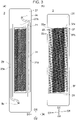
- FIG. 3A is a planar see-through view of the head 3 seen from the opposite side from the side where the ejection surface 3a is located. In this figure, the shape of the second flow path member 27 and the actuator 21 are illustrated.
- the second flow path member 27 has two grooves (refer to reference symbols 29 and 31) formed in the surface on the side where the first flow path member 25 is located. These two grooves are blocked by the first flow path member 25 and form a supply reservoir 29 and a collection reservoir 31 illustrated in FIGs. 2B and 3A .
- the supply reservoir 29 leads to the supply port 3b and is a flow path that supplies liquid supplied to the supply port 3b to the flow path of the first flow path member 25.
- the collection reservoir 31 leads to the collection port 3c and is a flow path that collects liquid from the flow path of the first flow path member 25 and guides the collected liquid to the collection port 3c.
- the supply reservoir 29 and the collection reservoir 31 include, for example, portions (main portions 29a and 31a) that extend in a straight line along the longitudinal direction (directions D2 and D5) of the head 3.
- the main portions 29a and 31a have, for example, lengths that span the length, in the longitudinal directions (directions D2 and D5), of the region in which a plurality of nozzles (described later) is arranged (refer to the arrangement region of the actuator 21 in FIG. 3A ).
- the main portion 29a and 31a are located on opposite sides from each other in the lateral direction of the head 3 (directions D3 and D6) with respect to the arrangement region of the plurality of nozzles.
- the shapes, dimensions, and so forth of the supply reservoir 29 and the collection reservoir 31 may be described while focusing only on the main portions 29a and 31a.
- the supply port 3b leads to one end (the end in the direction D2) of the supply reservoir 29.
- the other end (the end in the direction D5) of the supply reservoir 29 is a dead end (in other words, closed).
- the liquid in the supply reservoir 29 flows in the direction from the one end to the other end (in the direction D5).
- the collection port 3c leads to one end (in the direction D5) of the collection reservoir 31.
- the other end of the collection reservoir 31 (the end in the direction D2) is a dead end (in other words, closed).
- the liquid in the collection reservoir 31 flows in the direction from the other end to the one end (in the direction D5).
- the direction in which the liquid in the supply reservoir 29 flows and the direction in which the liquid in the collection reservoir 31 flows are identical to each other in the illustrated example. However, these directions may instead be opposite to each other.
- the supply reservoir 29 may include only the main portion 29a or may additionally include other portions. In the illustrated example, the supply reservoir 29 includes a portion (reference symbol omitted) that extends from the main portion 29a diagonally in the longitudinal direction of the head 3 to the supply port 3b. Similarly, the collection reservoir 31 may include only the main portion 31a or may additionally include other portions. In the illustrated example, the collection reservoir 31 includes a portion (reference symbol omitted) that extends diagonally in the longitudinal direction of the head 3 from the main portion 31a to the collection port 3c.
- the cross-sectional shapes and dimensions of the supply reservoir 29 and the collection reservoir 31 may be constant regardless of the position along the longitudinal directions of these flow paths or may vary with position. In the description of the embodiments, the former may be taken as an example.
- the cross-sectional shapes may be an appropriate shape such as a rectangular shape.
- the various dimensions of the supply reservoir 29 and the collection reservoir 31 may be set as appropriate in accordance with the specific technical field to which the ejecting device 1 is to be applied.
- the second flow path member 27 has slits 27a ( FIGs. 2A and 2B ) through which the signal transmission members 23 are inserted and a recess 27b ( FIGs. 2B and 3A ) in which the actuator 21 is housed.
- the slits 27a for example, penetrate through the second flow path member 27 from the side where the first flow path member 25 is located to the opposite side and extend along the longitudinal direction of the head 3.
- the recess 27b has a planar shape that is, for example, one size larger than the actuator 21, and the planar shape is a rectangular shape having a longitudinal direction matching the longitudinal direction of the head 3 in the illustrated example.
- the material and so forth of the second flow path member 27 may be chosen as appropriate.
- the second flow path member 27 may be composed of a metal, a resin, a ceramic, or a combination of any of these materials.
- FIG. 3B is a planar see-through view of the head 3. In this figure, the shape of the first flow path member 25 and the actuator 21 are illustrated.
- FIG. 4 is an enlarged view of a region IV in FIG. 3B .
- the flow path of the first flow path member 25 includes a plurality of supply manifolds 33 into which liquid is supplied from the supply reservoir 29 and a plurality of individual flow paths 35 into which liquid is supplied from the supply manifolds 33.
- the individual flow paths 35 include nozzles (described later) that eject droplets from the ejection surface 3a.
- the flow path of the first flow path member 25 also includes a plurality of collection manifolds 37 that collects liquid from the plurality of individual flow paths 35 and guides the collected liquid to the collection reservoir 31.
- the first flow path member 25 may include other flow paths that are located in the directions D2 and D5 relative to the plurality of supply manifolds 33, the plurality of individual flow paths 35, and the plurality of collection manifolds 37 and that connect the supply reservoir 29 and the collection reservoir 31 to each other. Such flow paths contribute to, for example, making the temperature of the first flow path member 25 uniform.
- the supply manifolds 33 include, for example, main portions 33a (corresponding to the entirety of the supply manifolds 33 in the illustrated example) that extend in straight lines along the direction D4 from the side near the supply reservoir 29 to the side near the collection reservoir 31.
- the direction D4 is inclined with respect to the lateral direction of the head 3 (direction D6).
- the collection manifolds 37 include, for example, main portions 37a (corresponding to the entirety of the collection manifolds 37 in the illustrated example) that extend in straight lines along the direction D1 from the side near the collection reservoir 31 to the side near the supply reservoir 29.
- the direction D1 is inclined with respect to the lateral direction of the head 3 (direction D3).
- the shape, dimensions, and so forth of the supply manifolds 33 and the collection manifolds 37 may be described while focusing only on the main portions 33a and 37a for convenience.
- the one ends lead to the supply reservoir 29 via openings 33b in a surface of the first flow path member 25 on the side where the second flow path member 27 is located.
- the other ends of the supply manifolds 33 (the ends in the direction D4) are dead ends. Therefore, the liquid in the supply reservoir 29 is supplied to the one ends of the supply manifolds 33 through the openings 33b and flows through the insides of the supply manifolds 33 in the direction from the one ends to the other ends of the supply manifolds 33 (direction D4).
- the one ends lead to the collection reservoir 31 via openings 37b in a surface of the first flow path member 25 on the side where the second flow path member 27 is located.
- the other ends (ends in the direction D1) of the collection manifolds 37 are dead ends. Therefore, the liquid in the collection manifolds 37 flows in the direction from the other ends to the one ends (direction D4) and is collected in the collection reservoir 31 through the openings 37b.
- the supply manifolds 33 and the collection manifolds 37 have lengths that span the length, in the lateral directions (directions D3 and D6), of the region in which the plurality of nozzles is arranged (described later) (refer to the arrangement region of the actuator 21).
- the ends of the supply manifolds 33 on the side near the collection reservoir 31 are located, for example, nearer the supply reservoir 29 than the collection reservoir 31.
- the ends of the collection manifolds 37 on the side near the supply reservoir 29 (the ends in the direction D1) are located, for example, nearer the collection reservoir 31 than the supply reservoir 29.
- the supply manifolds 33 have identical configurations to each other and are arranged at a constant pitch along the direction D2. In other words, the supply manifolds 33 extend parallel to each other and have the same length. The positions at which the supply manifolds 33 are connected to the supply reservoir 29 (openings 33b) are arranged at a constant pitch along the supply reservoir 29.
- the collection manifolds 37 have identical configurations and are arranged at a constant pitch along the direction D2. In other words, the collection manifolds 37 extend parallel to each other and have the same length. The positions at which collection manifolds 37 are connected to the collection reservoir 31 (openings 37b) are arranged at a constant pitch along the collection reservoir 31.
- the plurality of supply manifolds 33 and the plurality of collection manifolds 37 are, for example, arranged in an alternating manner at a constant pitch.
- the supply manifolds 33 and the collection manifolds 37 are adjacent to each other and extend parallel to each other. More specifically, the major portions of the supply manifolds 33, except for the upstream parts thereof, and the major portions of the collection manifolds 37, except for the downstream parts thereof, are adjacent to each other in the region where the plurality of nozzles is arranged.
- the cross-sectional shapes and dimensions of the supply manifolds 33 and the collection manifolds 37 may be constant regardless of the position along the longitudinal directions of these flow paths or may vary with position. In the description of the embodiments, the former may be taken as an example.
- the cross-sectional shapes may be an appropriate shape such as a rectangular shape.
- the various dimensions of the supply manifolds 33 and the collection manifolds 37 may be set as appropriate in accordance with the specific technical field to which the ejecting device 1 is to be applied.
- the individual flow paths 35 are roughly located between the supply manifolds 33 and the collection manifolds 37, which are adjacent to each other, and are connected to both the supply manifolds 33 and the collection manifolds 37.
- a plurality of individual flow paths 35 is provided for each set of manifolds (33 and 37).
- the individual flow paths 35 of the plurality of individual flow paths 35 connected to the same manifolds (33 and 37) are arranged along the manifolds (along the direction D1) at a certain pitch, for example, so as to form a single row of flow paths.
- the plurality of individual flow paths 35 is arranged in a matrix-like arrangement by arranging a plurality of rows of flow paths in the direction D2. Unlike in the illustrated example, two or more rows of individual flow paths 35 may be provided between adjacent supply and collection manifolds 33 and 37.
- the individual flow paths 35 of the plurality of individual flow paths 35 basically have identical configurations.
- the configurations of the plurality of rows of flow paths are basically the same as or similar to each other.
- the orientations of the individual flow paths 35 may be different between adjacent rows of flow paths (illustrated example).
- the shapes and/or dimensions of the plurality of individual flow paths 35 may slightly vary from one another.
- the flow path rows located at the end in the direction D2 and at the end in the direction D5 may include so-called dummy individual flow paths that do not eject droplets.
- the individual flow paths 35 include nozzles 43 that are open at the ejection surface 3a and eject droplets. Rows composed of a plurality of nozzles 43 arranged in the direction D1 are referred to as nozzle rows.
- the direction in which the nozzles 43 are arranged within each nozzle row (direction D1) is inclined with respect to the direction of relative movement of the head 3 with respect to the object 101 (direction D3).
- the nozzles 43 belonging to the same nozzle row are located at different positions from each other in the direction D2 due to this inclination.
- the nozzle rows partially overlap each other in the direction D3. In these overlapping portions, the nozzles 43 of one nozzle row and the nozzles 43 of another nozzle row are located at different positions in the direction D2.
- thirty-two nozzles 43 are projected within the range of a virtual straight line R and the nozzles 43 are arrayed at intervals of 360 dpi within the range of the virtual straight line R.
- printing can be performed with a resolution of 360 dpi when the object 101 and the head 3 are moved relative to each other in a direction perpendicular to the virtual straight line R and droplets are ejected.
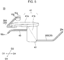
- FIG. 5 is a perspective view of one individual flow path 35.
- FIGs. 6A and 6B are cross-sectional views of the first flow path member 25 and the actuator 21.
- FIG. 6A corresponds to a line Via-Via in FIG. 5 .
- FIG. 6B corresponds to a line VIb-VIb in FIG. 5 .
- the individual flow path 35 includes, for example, supply flow paths 39 (first supply flow path 39A and second supply flow path 39B) connected to the corresponding supply manifold 33, a pressure chamber 41 connected to the supply flow paths 39, and a nozzle 43 connected to the pressure chamber 41.
- the nozzle 43 opens at the ejection surface 3a and leads to outside the first flow path member 25. Liquid from the supply manifold 33 is supplied to the nozzle 43 via the supply flow paths 39 and the pressure chamber 41. Then, when pressure is applied to the pressure chamber 41 by the actuator 21, a droplet is ejected from the nozzle 43.
- the individual flow path 35 also includes the collection flow path 45 connecting the pressure chamber 41 and the corresponding collection manifold 37 to each other. Liquid remaining in the pressure chamber 41 without being ejected is collected from the collection flow path 45 to the collection manifold 37.
- the pressure chamber 41 includes, for example, a pressure chamber body 41a to which pressure is applied by the actuator 21 and a descender 41b that connects the pressure chamber body 41a to the nozzle 43.
- the pressure chamber body 41a for example, is open to the pressurized surface 25a of the first flow path member 25 and is blocked by the actuator 21. Pressure is applied to the liquid inside the pressure chamber body 41a when the actuator 21 bends and deforms upward and/or downward.
- the descender 41b extends from the lower surface of the pressure chamber body 41a towards the ejection surface 3a.
- the cross-sectional area of the descender 41b is smaller than the area of a cross section of the pressure chamber body 41a parallel to the pressurized surface 25a.
- the shape and dimensions of the pressure chamber body 41a may be set as appropriate.
- the pressure chamber body 41a has a circular planar shape.
- the planar shape of the pressure chamber body 41a may be a shape other than a circle, such as an ellipse or a rhombus, for example.
- the pressure chamber body 41a has a thin shape having a thickness that is smaller than the diameter in plan view.
- the shape and dimensions of a cross section of the pressure chamber body 41a parallel to the pressurized surface 25a are constant in the vertical direction. However, the shape and/or dimensions of the cross section of the pressure chamber body 41a may be different at different positions in the vertical direction.
- the shape and dimensions of the descender 41b may also be set as appropriate.
- the shape of the descender 41b is a straight column.
- the cross-sectional shape is circular.
- the descender 41b may be inclined with respect to the vertical direction or may vary in diameter with respect to position in the vertical direction.
- the cross-sectional shape may be a shape other than a circular shape such as an elliptical shape.
- the position at which the descender 41b is connected to the pressure chamber body 41a in plan view may also be chosen as appropriate.
- the descender 41b is connected adjacent to the outer edge of the circular pressure chamber body 41a.
- the descender 41b may be connected to an end of the pressure chamber body 41a in the longitudinal direction.
- the nozzle 43 opens at a portion of the bottom surface of the descender 41b.
- the nozzle 43 may, for example, open at the center of the bottom surface of the descender 41b or may open at a position spaced away from the center of the bottom surface of the descender 41b (example illustrated in the figures).
- the shape of a longitudinal section of the nozzle 43 is tapered, with the diameter decreasing toward the ejection surface 3a. However, part or the entirety of the nozzle 43 may be reverse tapered.
- the shape of the cross section of the nozzle 43 is, for example, circular.
- the supply flow paths 39 include, for example, the first supply flow path 39A and the second supply flow path 39B. Unlike in the illustrated example, the supply flow paths 39 may include only one out of the first supply flow path 39A and the second supply flow path 39B.
- the positions at which the supply flow paths 39 are connected to the supply manifold 33 and the pressure chamber 41, and the shapes and dimensions of the supply flow paths 39 may be chosen as appropriate. In the illustrated example, the following is illustrated.
- the first supply flow path 39A connects the supply manifold 33 to the pressure chamber body 41A.
- the first supply flow path 39A extends upward from the upper surface of the supply manifold 33, then extends in the direction D5, then extends in the direction D4, and then extends upward again so as to connect to the lower surface of the pressure chamber body 41a.
- the cross-sectional shape and dimensions of the first supply flow path 39A are generally constant across the majority (for example, 60% or more) of the length of the first supply flow path 39A.
- the shape of the cross section across the majority of the length is rectangular.
- the second supply flow path 39B connects the supply manifold 33 to the descender 41b.
- the second supply flow path 39B extends from the lower surface of the supply manifold 33 in the direction D5 and then in the direction D1, and is connected to a side surface of the descender 41b.
- the cross-sectional shape and dimensions of the second supply flow path 39B are generally constant across the majority (for example, 60% or more) of the length of the second supply flow path 39B.
- the shape of the cross section across the majority of the length is rectangular.
- Only one collection flow path 45 is provided in a single individual flow path 35, for example. Unlike in the illustrated example, two or more collection flow paths 45 may be provided.
- the position at which the collection flow path 45 is connected to the collection manifold 37, the position at which the collection flow path 45 is connected to the pressure chamber 41, and the shape and dimensions of collection flow path 45 may be chosen as appropriate. In the illustrated example, the following is illustrated.
- the collection flow path 45 connects the collection manifold 37 to descender 41b.
- the collection flow path 45 extends from a side surface of the collection manifold 37 in the direction D2 and then in the direction D4 before connecting to a side surface of the descender 41b.
- the shape and dimensions of the cross section of the collection flow path 45 are generally constant across the majority (for example, 60% or more) of the length of the collection flow path 45.
- the shape of the cross section across the majority of the length is rectangular.
- the first flow path member 25 is formed by stacking a plurality of plates 47A to 47M.
- the various flow paths of the first flow path member 25 consist of holes or recesses formed in the plates 47A to 47M.
- the plurality of plates 47A to 47M may be formed of a metal or a resin, for example.
- dampers reference symbols omitted are provided above and below the collection manifold 37.
- the pressure chamber 41 is open at the pressurized surface 25a.
- a plate may be provided in order to close the pressure chamber 41.
- this case can be regarded as a question of whether a plate closing the pressure chamber 41 is regarded as being part of the first flow path member 25 or as being part of the actuator 21. In the description of the present disclosure, such a plate will be considered as being part of the actuator 21.
- the actuator 21 is, for example, a roughly flat plate-shaped member, and is bonded to the pressurized surface 25a of the first flow path member 25 (more precisely, the area indicated by the dotted line in FIG. 2A ). As illustrated in FIGs. 6A and 6B , the actuator 21 closes the opening at the top of the pressure chamber 41.
- the actuator 21 basically extends across the region where all the pressure chambers 41 are arranged.
- the actuator 21 includes a displacement element 49 for each pressure chamber 41.
- the actuator 21 may have any of various known configurations and may be an application of a known configuration.
- the actuator 21 is a so-called unimorph piezoelectric actuator. A specific configuration is described below.
- the actuator 21 includes a diaphragm 51, a common electrode 53, a piezoelectric layer 55, and individual electrodes 57, which are stacked in order from the side near the pressure chambers 41.
- the diaphragm 51, the common electrode 53, and the piezoelectric layer 55 basically extend across the region where all the pressure chambers 41 are arranged.
- the individual electrodes 57 are provided for each of the pressure chambers 41.
- the individual electrodes 57 for example, have similar shapes to the planar shapes of the pressure chambers 41 in a planar see-through view, and also overlap the centers of the pressure chambers 41.
- the portions of the piezoelectric layer 55 sandwiched between the individual electrodes 57 and the common electrode 53 are polarized in the thickness direction. Therefore, when a voltage is applied between the individual electrodes 57 and the common electrode 53, the piezoelectric layer 55 contracts or expands in directions along the surfaces. This contraction or expansion is restricted by the diaphragm 51, and the displacement elements 49 bend towards the side near the pressure chambers 41 or towards the opposite side like a bimetal. As a result, pressure is applied to the liquid in the pressure chambers 41.
- each layer of the actuator 21 may be chosen as appropriate.
- the diaphragm 51 and the piezoelectric layer 55 may be, for example, composed of lead zirconate titanate (PZT)-based, NaNbO 3 -based, BaTiO 3 -based, (BiNa)NbO 3 -based, or BiNaNb 5 O 15 -based ceramic materials.
- the common electrode 53 and individual electrodes 57 may be composed of, for example, Ag-Pd-based or Au-based metallic materials.
- the common electrode 53 for example, is given a constant potential (reference potential).
- a drive signal is, for example, input to the individual electrodes 57, as described previously.
- the method used to drive the displacement elements 49 may be chosen as appropriate.
- the driving method may be a so-called pull-hit method.
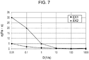
- FIG. 7 illustrates characteristics of a liquid used in the ejecting device 1.
- the horizontal axis represents shear rate D (1/s).
- the vertical axis represents viscosity ⁇ (Pa ⁇ s).
- EX1 and EX2 represent the characteristics of a first example and a second example of a liquid used in the ejecting device 1.
- the liquid used in the ejecting device 1 is a pseudoplastic fluid.
- a pseudoplastic fluid can be described as a non-Newtonian fluid having a viscosity that decreases with increasing shear rate.
- Shear rate is sometimes referred to as shear velocity, velocity gradient, or strain rate.
- Shear rate is calculated, for example, by simply dividing the difference in velocity between two positions separated from each other in a direction perpendicular to the flow direction by the distance between the two positions. Viscosity, for example, is conveniently calculated by dividing the shear stress by the shear rate.
- Shear stress is sometimes referred to as shearing stress.
- shear stress is calculated by dividing the force required to shift, in the flow direction, two parallel surfaces (of the same area) that are separated from each other in a direction perpendicular to the flow direction by the area of one of the surfaces.
- k is the viscosity coefficient and D is the shear rate. Since the viscosity ⁇ is a function of D, the viscosity ⁇ is sometimes referred to as apparent viscosity.
- the liquid used in the ejecting device 1 may have or not have thixotropic properties where the viscosity decreases with increasing time under shear stress.
- the specific constituents and/or composition of the pseudoplastic fluid may be various known ones or applications of known ones.
- inks and paints are typically pseudoplastic fluids.
- the liquids of the first and second examples, whose properties are illustrated in FIG. 7 are common paints (in other words, paints available on the market).
- the specific characteristics of the pseudoplastic fluids may also be chosen as appropriate.
- One example is as follows.
- the liquid may have a viscosity from 0.02 Pa ⁇ s to 0.4 Pa ⁇ s at a shear rate of 1000 s -1 .
- the viscosity is 0.3 Pa ⁇ s at a shear rate of 1000 s -1 .
- the viscosity is 0.1 Pa ⁇ s at a shear rate of 1000 s -1 .
- the liquid may have a viscosity from 0.1 Pa ⁇ s to 0.3 Pa ⁇ s at a shear rate of 1000 s -1 .
- the liquid may have a viscosity from 0.5 Pa ⁇ s to 50 Pa ⁇ s at a shear rate of 0.01 s -1 .
- the paint of the first example whose characteristics are illustrated in FIG. 7 , has a viscosity of 5 Pa ⁇ s at a shear rate of 0.01 s -1 .
- the paint of the second example has a viscosity of 30 Pa ⁇ s at a shear rate of 0.01 s -1 .
- the liquid may have a viscosity from 5 Pa ⁇ s to 30 Pa ⁇ s at a shear rate of 0.01 s -1 .
- the liquid may have a viscosity coefficient k from 1.0 to 1.5 and a power exponent p from 0.35 to 0.65 when the viscosity is approximated using a power law.
- the paint of the first example has a viscosity coefficient k of 1.0 and a power exponent p of 0.65.
- the paint of the second example has a viscosity coefficient k of 1.5 and a power exponent p of 0.35. Approximation equations may be specified, for example, using a method of least squares.
- each minute region inside the flow path has a different value of viscosity.
- average viscosities There is one value of average viscosity for each part within the flow path. For example, "the average viscosity of one supply manifold 33" means the average viscosity of the entire one supply manifold 33.
- the average viscosity may be calculated, for example, as follows. First, the relationship between the shear rate D and the viscosity ⁇ of the liquid used in the ejecting device 1 is identified. Various known methods may be employed or known literature may be referenced in order to make this identification. Next, an approximation equation representing the identified relationship between the shear rate D and the viscosity ⁇ is obtained. The approximation equation may be, for example, appropriate equation such as a power law.
- the fitting method used may be a known method such as the method of least squares.
- the flow rate U is different on the upstream side and the downstream side.
- the highest flow rate, the lowest flow rate, or the average flow rate may be used.
- the average viscosity in the following description may be assumed to be calculated using any of the above flow rates.
- average viscosities calculated using the highest flow rates may be compared to each other, average viscosities calculated using the lowest flow rates (highest average viscosities) may be compared to each other, or average viscosities calculated using the average flow rates (average average viscosities) may be compared to each other.
- average viscosity used in the following description may be taken as meaning an average viscosity calculated using the highest flow rate (lowest average viscosity).
- the average viscosities of the supply reservoir 29 and the supply manifolds 33 may be taken as being calculated using the furthest upstream flow rates.
- the average viscosities of the collection reservoir 31 and collection manifolds 37 may be taken as being calculated using the furthest downstream flow rates.
- the direction of liquid flow is not always constant.
- the average viscosity in these parts in the following description is calculated with a direction of flow from above to below as the flow direction.
- the average viscosity in the descender 41b is calculated with the flow direction being a direction from the pressure chamber body 41a to the nozzle 43.
- FIG. 8 illustrates an example of the relative relationships between different parts of the flow path of the flow path member 19 with respect to the average viscosities ⁇ of the respective parts of the flow path of the flow path member 19.
- the horizontal axis represents the plurality of parts of the flow path of the flow path member 19.
- the vertical axis represents the average viscosities ⁇ of the individual parts.
- an average viscosity ⁇ 2 represents the average viscosity ⁇ in one supply manifold 33 out of the plurality of supply manifolds 33.
- the average viscosity ⁇ in one flow path is illustrated.
- An average viscosity ⁇ 3 of the supply flow path 39 may be taken as being the average viscosity of either the first supply flow path 39A or the second supply flow path 39B.
- the target flow rate for the circulation flow rate controlled by the flow rate setting unit 13 and the shape and dimensions of the flow path of the flow path member 19 are set so that the relationship between the average viscosities as illustrated in the figure is satisfied.
- the flow path of the flow path member 19 has a flow path shape that satisfies the relationship illustrated in FIG. 8 when the circulation flow rate is equal to the target flow rate.
- the circulation flow rate is set to a value such that the relationship between the average viscosities illustrated in FIG. 8 is established for the shape and dimensions of the flow path of the flow path member 19.
- the circulation flow rate is set to a value such that the average viscosity of the liquid in the supply flow path 39 is less than or equal to half the average viscosity of the liquid in the supply manifold 33 for the shape and dimensions of the flow path of the flow path member 19.
- the circulation flow rate When the circulation flow rate is adjusted via open-loop control, there are large fluctuations in the circulation flow rate caused by the amounts of droplets ejected from the plurality of nozzles 43.
- the relationship illustrated in FIG. 8 may be established, for example, for the circulation flow rate at a time when droplets are not being ejected from any of the nozzles 43.
- the circulation flow rate at a time when droplets are not being ejected from any of the nozzles 43 in the product being implemented may be specified as the target flow rate of that product.
- This concept may also be applied to feedback control in which it takes more time for the circulation flow rate to become the target flow rate.
- the average viscosity ⁇ 3 of the liquid in the supply flow path 39 may be lower than the average viscosity ⁇ 2 of the liquid in the supply manifold 33. More specifically, for example, the average viscosity ⁇ 3 may be less than or equal to 1/2, 1/3, or 1/5 the average viscosity ⁇ 2.
- the liquid can be smoothly supplied from the supply flow path 39 to the pressure chamber 41 because the average viscosity ⁇ 3 of the liquid in the supply flow path 39 is low.
- the average viscosity ⁇ 2 is high in the supply manifold 33, pressure waves are easily attenuated. As a result, the likelihood of pressure waves that have leaked from the pressure chamber 41 to the supply manifold 33 via the supply flow path 39 propagating to another pressure chamber 41 via another supply flow path 39 is reduced. In other words, so-called fluid crosstalk can be reduced.
- an average viscosity ⁇ 5 of the liquid in the collection flow path 45 may be lower than an average viscosity ⁇ 6 of the liquid in the collection manifold 37. More precisely, for example, the average viscosity ⁇ 5 may be less than or equal to 1/2, 1/3, or 1/5 the average viscosity ⁇ 6. In this case, effects the same as or similar to those described above are achieved.
- the average viscosity ⁇ 2 of the supply manifold 33 may be lower than an average viscosity ⁇ 1 of the supply reservoir 29. More particularly, for example, the average viscosity ⁇ 2 may be less than or equal to 1/2, 1/3, or 1/4 the average viscosity ⁇ 1.
- the low average viscosity ⁇ 2 of the liquid inside the supply manifold 33 enables the liquid to be supplied smoothly from the supply manifold 33 to the supply flow path 39.
- the high viscosity inside the supply reservoir 29 makes it more likely for pressure waves to be attenuated, and consequently crosstalk caused by the propagation of pressure waves through the supply reservoir 29 can be reduced.
- the average viscosity ⁇ 6 of the liquid in the collection manifold 37 may be lower than an average viscosity ⁇ 7 of the liquid in the collection reservoir 31. More precisely, for example, the average viscosity ⁇ 6 may be less than or equal to 1/2, 1/3, or 1/5 the average viscosity ⁇ 7. In this case, effects the same as or similar to those described above are achieved.
- An average viscosity ⁇ 4 of the descender 41b may be higher than the average viscosity ⁇ 5 of the collection flow path 45. More specifically, for example, the average viscosity ⁇ 4 may be greater than or equal to 1.5 times the average viscosity ⁇ 5.
- the average viscosity ⁇ 4 of the descender 41b may be higher than the average viscosity ⁇ 3 of the supply flow path 39. More specifically, for example, the average viscosity ⁇ 4 may be greater than or equal to 1.5 times or 2 times the average viscosity ⁇ 3.
- the low average viscosity ⁇ 3 of the supply flow paths 39 enables the liquid to be smoothly supplied to the descender 41b.
- the likelihood of the liquid not being supplied to the descender 41b in time due to continuous ejection of the liquid is reduced.
- the average viscosity ⁇ 2 of the supply manifold 33 may be higher than the average viscosities ( ⁇ 3, ⁇ 4, and ⁇ 5) of the individual flow path 35 (excluding the pressure chamber body 41a). More particularly, for example, the average viscosity ⁇ 2 may be greater than or equal to 1.5 times any of the average viscosities ⁇ 3, ⁇ 4 and ⁇ 5.
- the liquid can be supplied smoothly to the nozzle 43 due to the low average viscosity ⁇ of the individual flow path 35.
- the high average viscosity ⁇ of the supply manifold 33 causes leaking of pressure from the individual flow path 35 into the supply manifold 33 to be rapidly attenuated. Therefore, fluid crosstalk is unlikely to occur.
- the average viscosity ⁇ 6 of the liquid in the collection manifold 37 may be higher than the average viscosities ( ⁇ 3, ⁇ 4, and ⁇ 5) of the individual flow path 35. More precisely, for example, the average viscosity ⁇ 6 may be greater than or equal to 1.5 times any of the average viscosities ⁇ 3, ⁇ 4 and ⁇ 5. In this case, effects the same as or similar to those described above are achieved.
- the circulation flow rate may be, for example, from 50 ml/min to 300 ml/min.
- the pressure in the nozzles 43 when liquid is not being ejected may be ⁇ 2 kPa with respect to atmospheric pressure (around 100 kPa).
- the differential pressure between the supply port 3b and the collection port 3c may be from 40 kPa to 160 kPa.
- the supply reservoir 29 and the collection reservoir 31 may each have a width w from 4 mm to 20 mm, a height h from 3 mm to 15 mm, and a length L from 200 mm and 800 mm.
- the supply manifolds 33 and the collection manifolds 37 may each have a width w from 0.2 mm to 2 mm, a height h from 0.5 mm to 6 mm, and a length L from 5 mm to 20 mm.
- the first supply flow paths 39A may have a width w and a height h from 50 ⁇ m to 200 ⁇ m.
- the second supply flow paths 39B may have a width w from 50 ⁇ m to 200 ⁇ m and a height h from 25 ⁇ m to 200 ⁇ m.
- the collection flow paths 45 may have a width w from 70 ⁇ m to 200 ⁇ m and a height h from 80 ⁇ m to 200 ⁇ m.
- the length L of the supply flow paths 39 and the collection flow paths 45 may be from 300 ⁇ m to 1500 ⁇ m.
- the descenders 41b may have a radius r from 50 ⁇ m to 250 ⁇ m and a length L from 0.5 mm to 2 mm.
- the nozzles 43 may have a radius r from 5 ⁇ m to 50 ⁇ m.
- the average viscosity ⁇ in the descenders 41b was calculated using Equation (1) and the average viscosities ⁇ of the other flow paths was calculated using Equation (2).
- the average viscosity ⁇ in the supply reservoir 29 and the collection reservoir 31 is from 0.4 Pa s to 2 Pa s.
- the average viscosity ⁇ in the supply manifold 33 and the collection manifold 37 is from 0.1 Pa ⁇ s to 0.4 Pa ⁇ s.
- the average viscosity ⁇ in the supply flow paths 39 and the collection flow paths 45 is from 0.01 Pa ⁇ s to 0.1 Pa ⁇ s.
- the average viscosity ⁇ in the descenders 41b is from 0.05 Pa ⁇ s to 0.2 Pa ⁇ s.
- the fluid resistance (N-s/m5) in the flow path member 19 may be set as appropriate.
- the fluid resistance may be set so that both Condition 1 and Condition 2 below are satisfied.
- the sum of 1 / 2 ⁇ R r ⁇ U 1 + 1 / m and 1 / 2 ⁇ R m ⁇ U / m ⁇ 1 + 1 / n is smaller than 2 ⁇ / r .
- R r is the fluid resistance of the liquid in the supply reservoir 29.
- R m is the fluid resistance of the liquid in the supply manifolds 33.
- m is the number of supply manifolds 33 connected to the supply reservoir 29.
- n is the number of individual flow paths 35 (nozzles 43) per supply manifold 33.
- U is the flow rate (m 3 /s) of the liquid flowing into the supply reservoir 29.
- ⁇ is the surface tension (N/m) of the liquid.
- r is the radius (m) of each nozzle 43.
- the supply manifolds 33 to which only dummy individual flow paths not capable of ejecting droplets are connected are ignored. It is also assumed that the same number of nozzles 43 are connected to each supply manifold 33. It is also assumed that the pitch of the plurality of supply manifolds 33, the distance from the upstream end of the supply reservoir 29 to the first supply manifold 33, and the distance from the final supply manifold 33 to the downstream end of the supply reservoir 29 are equal to each other.
- Condition 1 corresponds to a pressure drop inside the supply reservoir 29 (pressure difference between upstream side and downstream side). Specifically, the pressure drop from the upstream end of the supply reservoir 29 to the first supply manifold 33 is calculated as U ⁇ R r /m, and the pressure drop from the first supply manifold 33 to the second supply manifold is calculated as (U - U/m) ⁇ R r /m.
- Condition 1 corresponds to the pressure drop (pressure difference between the upstream end and the downstream end) in one supply manifold 33.
- This equation is obtained in the same way or in a similar way to the pressure drop in the supply reservoir 29 described above. That is, in the equation for the supply reservoir 29, a fluid resistance R r of the supply reservoir 29 is replaced by a fluid resistance R m of the supply manifolds 33, a flow rate U into the supply reservoir 29 is replaced by a flow rate U/m of liquid into the supply manifolds 33, and the number m of supply manifolds 33 is replaced by replaced by the number n of nozzles 43.
- the sum of (1/2) ⁇ R r ⁇ U(1 + 1/m) and (1/2) ⁇ R m ⁇ (U/m) ⁇ (1 + 1/n) in Condition 1 roughly corresponds to the difference in pressure between the most upstream individual flow path 35 and the most downstream individual flow path 35.
- the most upstream individual flow path 35 is the individual flow path 35 connected furthest upstream to the supply manifold 33 that is connected furthest upstream to the supply reservoir 29.
- the most downstream individual flow path 35 is the individual flow path 35 connected furthest downstream to the supply manifold 33 that is connected to furthest downstream to the supply reservoir 29.
- the pressure drops in the individual flow paths 35 are substantially identical among the plurality of individual flow paths 35 and therefore the above sum is equivalent to the pressure difference across all the nozzles 43 (the difference in pressure between the nozzle 43 having the highest pressure and the nozzle 43 having the lowest pressure).
- the most upstream supply manifold 33 or the most downstream supply manifold 33 may be ignored, or alternatively, it may be assumed that the most upstream supply manifold 33 or the most downstream supply manifold 33 has the same number of individual flow paths 35 connected thereto as the other supply manifolds 33.
- Condition 2 represents the relationship between the fluid resistance R r of the supply reservoir 29 and the fluid resistance R m of the supply manifolds 33. Since the flow rate of the fluid flowing into the supply manifolds 33 is 1/m of the flow rate of the fluid flowing into the supply reservoir 29, the fluid resistance R r is compared to the fluid resistance R m by multiplying the fluid resistance R m by 1/m. Condition 2 being satisfied means that the fluid resistance R r of the supply reservoir 29 is very small compared to the fluid resistance R m of the supply manifolds 33.
- R r is around 1/5 of R m ⁇ (1/m).
- R r may be greater than or equal to 1/40 of R m ⁇ (1/m) and less than 1/10 of R m ⁇ (1/m).
- R r may be around 1/5 of R m ⁇ (1/m), similarly to as in the technologies of the related art.
- the liquid readily flows from the supply reservoir 29 to the positions of the plurality of supply manifolds 33 and differences in flow rate between the plurality of supply manifolds 33 are reduced. Accordingly, the liquid can be stably supplied to all the supply manifolds 33.
- the fluid resistance may be set so that Condition 3 below is satisfied.
- R m ⁇ 1 / 10 ⁇ R n ⁇ 1 / n R n is the fluid resistance in the nozzles 43.
- Condition 3 represents the relationship between the fluid resistance R m of the supply manifolds 33 and the fluid resistance of the individual flow paths 35.
- the fluid resistance R n of the nozzles 43 is much greater than the fluid resistance of the other parts of the individual flow paths 35, the fluid resistance of the individual flow paths 35 is approximated by the fluid resistance R n of the nozzles 43. Since the flow rate of the liquid flowing into the individual flow paths 35 is 1/n of the flow rate of the liquid flowing into the supply manifolds 33, the fluid resistance R m is compared to the fluid resistance R n by multiplying the fluid resistance R n by 1/n.
- Condition 3 being satisfied means that the fluid resistance R m of the supply manifolds 33 is very small compared to the fluid resistance R n of the nozzles 43.
- R m is approximately 1/6 of R n ⁇ (1/n).
- R m may be around 1/6 of R n ⁇ (1/n).
- R m may be set to be from 1/10 to 1/4 of R n ⁇ (1/n).
- the liquid readily flows from the supply manifolds 33 to the positions of the plurality of individual flow paths 35 and differences in flow rate between the plurality of individual flow paths 35 are reduced. Accordingly, the liquid can be supplied stably to all the individual flow paths 35.
- the example of the dimensions and so forth of a flow path illustrated in FIG. 8 serving as an example of the dimensions that realize the average viscosities, may be referred to as an example of dimensions and so forth of a flow path for which Conditions 1 to 3 are satisfied.
- FIG. 9 is a schematic cross-sectional view of an individual flow path 235 according to a variation.
- a pressure chamber 241 of the individual flow path 235 includes a pressure chamber body 241a and a descender 241b, the same as or similar to the pressure chamber 41 of the embodiment.
- the descender 241b has a first portion 241ba and a second portion 241bb, which have different cross-sectional areas from each other.
- the first portion 241ba is connected to the nozzle 43.
- the second portion 241bb is connected to the pressure chamber body 241a.
- the second portion 241bb is a portion located nearer the pressure chamber body 241a than the first portion 241ba.
- the cross-sectional area of the second portion 241bb is larger than that of the first portion 241ba.
- the average viscosities of the first portion 241ba and the second portion 241bb are different from each other as a result of the first portion 241ba and the second portion 241bb having different cross-sectional areas from each other, for example.
- the average viscosity of the liquid in the second portion 241bb is higher than the average viscosity of the liquid in the first portion 241ba.
- the average viscosity in the descender 241b increases in a stepwise manner with increasing closeness to the pressure chamber body 41a from the nozzle 43.
- the average viscosity may increase not only in one step but also in two or more steps.
- the descender may include a third portion and so on, in addition to the first and second portions.
- the average viscosity of the second portion 241bb which is located nearer the pressure chamber body 241a than the first portion 241ba, is higher than the average viscosity of the first portion 241ba as in the present variation, for example, bubbles that have entered the descender 241b from the nozzle 43 have greater difficulty in moving towards the pressure chamber body 241a. Consequently, the likelihood of bubbles remaining in the pressure chamber body 241a and resulting in deterioration of the ejection characteristics is reduced.
- the average viscosities of the parts where the two flow paths contact each other may be compared with each other.
- the average viscosity of the second portion 241bb which is directly connected to the collection flow path 45, may be used for the purpose of comparison rather than the average viscosity of the entire descender 241b. This is because the average viscosity of the second portion 241bb has the greater effect on the flow between the collection flow path 45 and the descender 241b.
- the liquid ejecting device is not restricted to being a piezoelectric-type liquid ejecting device that applies pressure to a liquid through means of a piezoelectric body.
- the liquid ejecting device may be a thermal-type liquid ejecting device that generates bubbles within the liquid by heating the liquid and applies pressure to the liquid accompanying the generation of these bubbles in order to eject droplets.
- the flow paths may have various configurations other than those illustrated in the figures.
- individual flow paths that are adjacent to each other may share common portions with each other.
- portions of the collection flow paths on the side where the collection manifolds are located may be shared among the individual flow paths adjacent to each other.
- the average viscosities may also be set in a different manner from that described in the embodiment.
- the average viscosity ⁇ 3 of the supply flow path 39 may, in contrast to the embodiment, be larger than the average viscosity ⁇ 5 of the collection flow path 45 or may be 1.5 times higher.
- the liquid inside the descender 41b will be less likely to flow backwards (i.e., less likely to flow in the opposite direction from the circulation direction) during ejection of droplets.
- the liquid and/or bubbles are more likely to flow into the collection flow path.
Landscapes
- Particle Formation And Scattering Control In Inkjet Printers (AREA)
- Ink Jet (AREA)
- Coating Apparatus (AREA)
Abstract
Description
- The present disclosure relates to a liquid ejecting device and a liquid ejecting method.
- Liquid ejecting devices such as inkjet printers are known. In
Patent Literature 1, an inkjet recording device using a thixotropic ink is disclosed. - Patent Literature 1:
Japanese Unexamined Patent Application Publication No. 8-216425 - In an aspect of the present disclosure, a liquid ejecting device includes a flow path member, an actuator, and a flow rate setting unit. The flow path member includes a flow path along which a pseudoplastic liquid flows. The actuator applies pressure to the liquid in the flow path and cause droplets to be ejected from the flow path member. The flow rate setting unit sets the flow rate of the liquid in the flow path. The flow path includes a supply reservoir, a plurality of supply manifolds, a plurality of supply flow paths, a plurality of pressure chambers, a plurality of nozzles, a plurality of collection flow paths, and a collection reservoir. The liquid is supplied from the supply reservoir. The plurality of supply manifolds is connected to the supply reservoir and the liquid is supplied thereto from the supply reservoir. Two or more supply flow paths, among the plurality of supply flow paths, are provided for each of the plurality of supply manifolds. Each supply flow path among the plurality of supply flow paths is connected to a corresponding one of the plurality of supply manifolds. The liquid is supplied to the plurality of supply flow paths from the supply manifolds connected thereto. The plurality of pressure chambers is connected in a one-to-one manner to the plurality of supply flow paths, the liquid is supplied thereto from the plurality of supply flow paths, and pressure is applied to the liquid by the actuator. The plurality of nozzles is connected in a one-to-one manner to the plurality of pressure chambers and the liquid from the pressure chambers is ejected to the outside. The plurality of collection flow paths is connected in a one-to-one manner to the plurality of pressure chambers and collect the liquid from the plurality of pressure chambers. Each of the plurality of collection manifolds is connected to two or more of the plurality of collection flow paths and the plurality of collection manifolds collect the liquid from the plurality of collection flow paths. The collection reservoir is connected to the plurality of collection manifolds and collects the liquid from the plurality of collection manifolds. The flow rate setting unit adjusts the circulation flow rate of the liquid to a prescribed target flow rate, the liquid sequentially circulating through the supply reservoir, the plurality of supply manifolds, the plurality of supply flow paths, the plurality of pressure chambers, the plurality of collection flow paths, the plurality of collection manifolds, and the collection reservoir. The flow path has a flow path shape in which an average viscosity of the liquid in the supply flow paths is less than or equal to half an average viscosity of the liquid in the supply manifolds when the circulation flow rate is equal to the target flow rate.
- In an aspect of the present disclosure, a liquid ejecting method uses the liquid ejecting device described above. In the liquid ejecting method, a pseudoplastic fluid whose viscosity is from 0.02 Pa·s to 0.4 Pa·s at a shear rate of 1000 s-1 and whose viscosity is from 0.5 Pa·s to 50 Pa·s at a shear rate of 0.01 s-1 is used as the liquid.
-
-
FIG. 1 is a schematic diagram illustrating the overall configuration of a liquid ejecting device according to an embodiment. -
FIG. 2A is an exploded perspective view of a head of the liquid ejecting device of the embodiment, andFIG. 2B is a perspective view of a second flow path member included in the head. -
FIGs. 3A and 3B are planar see-through views of the head according to the embodiment. -
FIG. 4 is an enlarged view of a region IV inFIG. 3B . -
FIG. 5 is a perspective view of an individual flow path of the head according to the embodiment. -
FIG. 6A is a cross-sectional view taken along a line Via-Via inFIG. 5 , andFIG. 6B is a cross-sectional view taken along a line VIb-VIb inFIG. 5 . -
FIG. 7 is diagram illustrating characteristics of a liquid used in the liquid ejecting device according to the embodiment. -
FIG. 8 is a diagram illustrating an example of the average viscosity in various parts of a flow path in the embodiment. -
FIG. 9 is a schematic cross-sectional view of an individual flow path according to a variation. - Embodiments of the present disclosure are described below while referring to the drawings. The following drawings are schematic drawings. Therefore, details may be omitted. In addition, the dimensional proportions do not necessarily correspond to the actual dimensional proportions. The dimensional proportions do not necessarily match each other from drawing to drawing. Certain dimensions may be depicted as being larger than they are in reality, and certain shapes may be depicted in an exaggerated manner.
- The drawings may include arrows representing directions D1 to D6. These directions are parallel to an
ejection surface 3a, which is described later. The directions D2 and D5 are, for example, parallel to a longitudinal direction of ahead 3, which is described later, and are so-called main scanning directions from another perspective. The directions D3 and D6 are perpendicular to the directions D2 and D5. The directions D1 and D4 are inclined with respect to the directions D3 and D6. -
FIG. 1 is a diagram schematically illustrating the main configuration of a liquid ejecting device 1 (hereinafter, may be referred to as "ejecting device 1") according to an embodiment. - The
ejecting device 1 is configured as a device that deposits a liquid onto a surface of anobject 101 by ejecting droplets from theejection surface 3a of thehead 3 towards theobject 101, such as an inkjet printer, for example. Theejection surface 3a may face in any direction with respect to the vertical direction, but in the following description, for convenience, the direction in which theejection surface 3a faces is a downward direction and terms such as upper surface or lower surface may be used. - The specific type (intended use) of the
ejecting device 1 may be any appropriate type. For example, the ejectingdevice 1 may be a device that prints characters and figures (or from another perspective, records information) by depositing ink onto a recording medium (for example, paper) serving as theobject 101. In other words, the ejectingdevice 1 may be a so-called printer. In addition, for example, the ejectingdevice 1 may be a device for decorating the body of an automobile by depositing paint onto the body of the automobile serving as theobject 101. In addition, for example, the ejectingdevice 1 may be a device that forms wiring by depositing a liquid containing conductive particles onto a circuit board serving as theobject 101. - Furthermore, unlike in the illustrated example, the ejecting
device 1 does not have to be a device that deposits a liquid onto theobject 101. For example, the ejectingdevice 1 may be a device that ejects into a container a liquid chemical that reacts with a substance inside the container, or may be a device that sprays a disinfectant solution into the air. - As is clear from the above examples of specific types of the
ejecting device 1, the material, shape and dimensions of theobject 101 may be chosen as appropriate. SinceFIG. 1 is a schematic diagram, theobject 101 is illustrated as a rectangular parallelepiped. The material of theobject 101 may be, for example, paper, cloth, resin, metal, ceramic, wood, or a combination of any of these materials. Types of theobject 101 may include recording media (for example, paper rolls or sheets), circuit boards, clothing, beverage containers, storage containers, electronic equipment housings, and automobile bodies. Theobject 101 or the area of theobject 101 onto which the liquid is to be deposited may be narrower or wider than theejection surface 3a from which droplets are ejected. - As is clear from the above examples of specific types of the
ejecting device 1, the type of liquid may also be chosen as appropriate. For example, the types of liquids may include inks, paints, liquids containing conductive particles, chemicals, and disinfectants. Inks and paints may be distinguished from each other by the presence or absence of organic solvents and/or a function of protecting the surface of theobject 101. However, such distinctions do not need to be made. In the following description, paint may be read as ink as appropriate. The reverse is also true. A paint may contain a pigment for the purpose of providing a color or may be pigment-free (colorless) without having the purpose of providing a color (for example, for the sole purpose of adding gloss and/or protecting the object 101). - The ejecting
device 1, for example, includes thehead 3 that ejects droplets and a movingunit 5 that moves thehead 3 relative to theobject 101. Thehead 3 has theejection surface 3a in which a plurality of nozzles (which are described later) for ejecting droplets is formed. The movingunit 5, for example, maintains a state in which theejection surface 3a and the surface of theobject 101 face each other and moves theejection surface 3a and the surface of theobject 101 relative to each other along theejection surface 3 a and the surface of theobject 101. The direction of relative movement is, for example, the direction D3 or D6. As can be understood from an inkjet printer, which is a specific example of theejecting device 1, droplets are deposited across a region having a larger area than the area of the region where the plurality of nozzles is arranged as a result of droplets being ejected from theejection surface 3a in synchronization with the relative movement described above. - The ejecting
device 1 includes, for example, a tank 7 in which liquid is stored. Thehead 3 has asupply port 3b for allowing liquid to be supplied from the tank 7 to thehead 3 and acollection port 3c for allowing liquid to be collected from thehead 3 to the tank 7. In other words, the liquid circulates through thehead 3 and the tank 7. Circulating the liquid in this way, for example, reduces the likelihood of the liquid stagnating inside thehead 3. This, in turn, reduces the likelihood of the stagnating liquid solidifying or components in the stagnating liquid precipitating. In addition, in this embodiment, the shear rate of the liquid can be adjusted, and therefore the viscosity of the liquid can be adjusted, as described below, by circulating the liquid. - The ejecting
device 1 includes acirculation actuation unit 9 that applies pressure to the liquid so as to cause the liquid to circulate and acontroller 11 that controls the various parts (for example, thehead 3, the movingunit 5, and the circulation actuation unit 9) of theejecting device 1. The combination of thecirculation actuation unit 9 and thecontroller 11 may be regarded as a flowrate setting unit 13 used to set the flow rate of the liquid circulating through the head 3 (hereinafter, referred to as the "circulation flow rate"). The circulation flow rate may be regarded, for example, as being the same as the flow rate of the liquid flowing from thecollection port 3c to outside thehead 3. - The ejecting
device 1 may include only one head 3 (and tank 7) as in the case of a monochrome printer, or may include multiple heads 3 (and multiple tanks 7) that eject different liquids from each other like in the case of a color printer. The ejectingdevice 1 may also includemultiple heads 3 that eject the same liquid as each other. There are advantages to providing a plurality ofheads 3 that eject the same liquid such as, for example, a reduction in the time taken to deposit liquid on a certain area and an improvement in dot density. In the following description, only onehead 3 will be referred to for convenience. - The moving
unit 5 can, for example, move theobject 101 relative to thehead 3 in at least one out of the directions D3 and D6. As has already been mentioned, this direction is the direction of movement when ejecting droplets and is a so-called sub-scanning direction. The movingunit 5 may be able to realize relative movement between thehead 3 and theobject 101 in directions other than the directions D3 and D6. Other directions in which relative movement may be realized include, for example, the directions D2 and D5, which are perpendicular to the directions D3 and D6, and directions perpendicular to theejection surface 3a (a direction in which thehead 3 and theobject 101 are brought closer together and a direction in which thehead 3 and theobject 101 are moved away from each other). The movingunit 5 may also be capable of realizing relative rotation between thehead 3 and theobject 101. - The moving
unit 5 may move only theobject 101, thehead 3, or both theobject 101 and thehead 3 in an absolute coordinate system. The specific configuration of the movingunit 5 may be appropriately decided upon in accordance with the specific type of theejecting device 1. - For example, in the case where the
ejecting device 1 is a so-called line printer, the movingunit 5 may be configured as a device for conveying a recording medium (for example, paper) as theobject 101. The device may, for example, include a plurality of rollers that generates a frictional force by contacting the recording medium and an electric motor that causes the plurality of rollers to rotate. In the case where theejecting device 1 is a so-called serial printer, for example, the movingunit 5 may include a device for conveying the recording medium as theobject 101 in a prescribed conveyance direction and a device for moving thehead 3 in a direction perpendicular to the conveyance direction and along the recording medium. - For example, the ejecting
device 1 may include a conveyor belt that conveys any type ofobject 101. For example, the ejectingdevice 1 may include a movable table on which any type ofobject 101 is placed. For example, the ejectingdevice 1 may include an industrial robot that moves any type ofobject 101 and/or an industrial robot that moves thehead 3. Examples of industrial robots may include vertical articulated robots (articulated robots in a narrow sense), SCARA robots, Cartesian robots, and parallel link robots. - The tank 7 and
circulation actuation unit 9 may be, for example, the same as or similar to a tank and a circulation actuation unit used in known inkjet printers that circulate liquids, or may be components to which such known tanks and circulation actuation units have been applied. - For example, the tank 7 may be configured to store the liquid to be supplied to the
head 3 and the liquid collected from thehead 3 in the same space. The tank 7 may also be configured to store the liquid to be supplied to thehead 3 and the liquid collected from thehead 3 in separate spaces and allow the liquid to flow from the latter space to the former space. In this case, the tank 7 may include two spaces realized by partitioning one tank with a partition wall or may include two spaces realized by including two tanks connected to each other by flow paths. The inside of the tank 7 (the space mentioned above) may be open to the atmosphere or sealed. In the latter case, the pressure inside the tank 7 may be adjusted to a suitable pressure using a valve or vacuum pump, for example. The tank 7 may include a main tank and a sub-tank having a smaller capacity than the main tank. The sub-tank functions as an intermediary between the main tank and thehead 3. - In the illustrated example, the
circulation actuation unit 9 includes apump 15 that pumps the liquid from the tank 7 to thehead 3, apressure sensor 17A that detects the pressure of the liquid on the side near thesupply port 3b, and apressure sensor 17B that detects the pressure of the liquid on the side near thecollection port 3c. Thecontroller 11, for example, performs feedback control on thepump 15 so that the pressure difference between thesupply port 3b and thecollection port 3c converges at a prescribed target value on the basis of the values detected by thepressure sensors - Unlike in the illustrated example, a
pump 15 that pumps the liquid from thecollection port 3c to the tank 7 may be provided instead of or in addition to thepump 15 on the side near thesupply port 3b. Instead of or in addition to thepump 15 pumping the liquid, liquid flow may be generated by controlling the pressure inside the tank 7 by using a vacuum pump or the like. Liquid flow may be generated by raising the liquid level in the tank containing the liquid to be supplied so as to be higher than the liquid level in the tank storing the collected liquid. - Instead of or in addition to the
pressure sensors head 3 and/or the flow rate of the liquid collected from thehead 3 and may be used in control of the circulation flow rate. As is understood from the various ways in which the liquid flow may be generated described above, instead of or in addition to these sensors, a sensor that detects the air pressure inside the tank 7 may be provided and used in control of the circulation flow rate. Open-loop control may be used without performing sensor-based feedback control. In other words, sensors do not have to be provided. - For example, the tank 7 and the
circulation actuation unit 9 are not moved in an absolute coordinate system by the movingunit 5. Therefore, for example, in a mode in which the movingunit 5 moves thehead 3 in the absolute coordinate system, thehead 3 moves relative to the tank 7 and thecirculation actuation unit 9 . In this case, thehead 3, the tank 7, and thecirculation actuation unit 9 may be connected to each other by flow paths consisting of, for example, flexible tubing. In a mode in which the movingunit 5 does not move thehead 3 in the absolute coordinate system, thehead 3 is fixed in place with respect to the tank 7 and thecirculation actuation unit 9. In this case, the configuration of the flow paths connecting thehead 3, the tank 7, and thecirculation actuation unit 9 to each other may be chosen as appropriate. Unlike in the above description, all or part of the tank 7 and/or thecirculation actuation unit 9 may move together with thehead 3. - The
controller 11 consists of, for example, a computer. Although not specifically illustrated, the computer includes a central processing unit (CPU), a read only memory (ROM), a random access memory (RAM), and an external storage device. Thehead 3, the movingunit 5, and thecirculation actuation unit 9 are controlled by executing programs stored in the ROM and/or external storage device. -
FIG. 2A is an exploded perspective view of thehead 3. - The
head 3 includes a flow path member 19 (reference symbol appears inFIG. 1 ), which has a flow path along which the liquid flows, anactuator 21 that applies pressure to the liquid in theflow path member 19, andsignal transmission members 23 for inputting drive signals to the actuator 21 (not illustrated inFIG. 1 ). Theflow path member 19 includes a firstflow path member 25 having theejection surface 3a and a secondflow path member 27 including thesupply port 3b and thecollection port 3c. The surface of the firstflow path member 25 on the opposite side from theejection surface 3a may be referred to as apressurized surface 25a. - The first
flow path member 25 and the secondflow path member 27 are formed in roughly flat plate like shapes and together form the roughly flat plate-shapedflow path member 19 when stacked one on top of the other. Liquid supplied to thesupply port 3b is supplied from the secondflow path member 27 to the firstflow path member 25 and is then ejected from theejection surface 3a. The remaining liquid that is not ejected flows from the firstflow path member 25 to the secondflow path member 27 and is collected from thecollection port 3c. - The
controller 11 outputs a control signal on the basis of prescribed data such as image data. The control signal is input, for example, via thesignal transmission members 23, to a driver, which is not illustrated, mounted on thesignal transmission members 23. The driver generates a drive signal having a predetermined waveform on the basis of the input control signal. The drive signal is input to theactuator 21 via thesignal transmission members 23. Theactuator 21 applies pressure to the liquid inside theflow path member 19 with a pressure waveform corresponding to the waveform of the drive signal. As a result, the liquid inside theflow path member 19 is ejected from theejection surface 3a. The division of roles between thecontroller 11 and the driver may be decided upon as appropriate, and the driver may be regarded as being part of thecontroller 11. -
FIG. 2B is a perspective view of the secondflow path member 27. More precisely, this figure is a view of the secondflow path member 27 from the side where the firstflow path member 25 is located, and the upper side of the sheet inFIG. 2B corresponds to the lower side of the sheet inFIGs. 1 and2A .FIG. 3A is a planar see-through view of thehead 3 seen from the opposite side from the side where theejection surface 3a is located. In this figure, the shape of the secondflow path member 27 and theactuator 21 are illustrated. - As illustrated in
FIG. 2B , the secondflow path member 27 has two grooves (refer to referencesymbols 29 and 31) formed in the surface on the side where the firstflow path member 25 is located. These two grooves are blocked by the firstflow path member 25 and form asupply reservoir 29 and acollection reservoir 31 illustrated inFIGs. 2B and3A . Thesupply reservoir 29 leads to thesupply port 3b and is a flow path that supplies liquid supplied to thesupply port 3b to the flow path of the firstflow path member 25. Thecollection reservoir 31 leads to thecollection port 3c and is a flow path that collects liquid from the flow path of the firstflow path member 25 and guides the collected liquid to thecollection port 3c. - The
supply reservoir 29 and thecollection reservoir 31 include, for example, portions (main portions head 3. Themain portions actuator 21 inFIG. 3A ). Themain portion supply reservoir 29 and thecollection reservoir 31 may be described while focusing only on themain portions - The
supply port 3b, for example, leads to one end (the end in the direction D2) of thesupply reservoir 29. The other end (the end in the direction D5) of thesupply reservoir 29 is a dead end (in other words, closed). The liquid in thesupply reservoir 29 flows in the direction from the one end to the other end (in the direction D5). Thecollection port 3c, for example, leads to one end (in the direction D5) of thecollection reservoir 31. The other end of the collection reservoir 31 (the end in the direction D2) is a dead end (in other words, closed). The liquid in thecollection reservoir 31 flows in the direction from the other end to the one end (in the direction D5). The direction in which the liquid in thesupply reservoir 29 flows and the direction in which the liquid in thecollection reservoir 31 flows are identical to each other in the illustrated example. However, these directions may instead be opposite to each other. - The
supply reservoir 29 may include only themain portion 29a or may additionally include other portions. In the illustrated example, thesupply reservoir 29 includes a portion (reference symbol omitted) that extends from themain portion 29a diagonally in the longitudinal direction of thehead 3 to thesupply port 3b. Similarly, thecollection reservoir 31 may include only themain portion 31a or may additionally include other portions. In the illustrated example, thecollection reservoir 31 includes a portion (reference symbol omitted) that extends diagonally in the longitudinal direction of thehead 3 from themain portion 31a to thecollection port 3c. - The cross-sectional shapes and dimensions of the
supply reservoir 29 and the collection reservoir 31 (for example, of themain portions supply reservoir 29 and thecollection reservoir 31 may be set as appropriate in accordance with the specific technical field to which theejecting device 1 is to be applied. - In the illustrated example, in addition to the two grooves serving as the
supply reservoir 29 and thecollection reservoir 31, the secondflow path member 27 hasslits 27a (FIGs. 2A and 2B ) through which thesignal transmission members 23 are inserted and arecess 27b (FIGs. 2B and3A ) in which theactuator 21 is housed. Theslits 27a, for example, penetrate through the secondflow path member 27 from the side where the firstflow path member 25 is located to the opposite side and extend along the longitudinal direction of thehead 3. Therecess 27b has a planar shape that is, for example, one size larger than theactuator 21, and the planar shape is a rectangular shape having a longitudinal direction matching the longitudinal direction of thehead 3 in the illustrated example. - The material and so forth of the second
flow path member 27 may be chosen as appropriate. For example, the secondflow path member 27 may be composed of a metal, a resin, a ceramic, or a combination of any of these materials. -
FIG. 3B is a planar see-through view of thehead 3. In this figure, the shape of the firstflow path member 25 and theactuator 21 are illustrated.FIG. 4 is an enlarged view of a region IV inFIG. 3B . - The flow path of the first
flow path member 25 includes a plurality ofsupply manifolds 33 into which liquid is supplied from thesupply reservoir 29 and a plurality ofindividual flow paths 35 into which liquid is supplied from thesupply manifolds 33. Theindividual flow paths 35 include nozzles (described later) that eject droplets from theejection surface 3a. The flow path of the firstflow path member 25 also includes a plurality ofcollection manifolds 37 that collects liquid from the plurality ofindividual flow paths 35 and guides the collected liquid to thecollection reservoir 31. - Although not specifically illustrated, the first
flow path member 25 may include other flow paths that are located in the directions D2 and D5 relative to the plurality ofsupply manifolds 33, the plurality ofindividual flow paths 35, and the plurality ofcollection manifolds 37 and that connect thesupply reservoir 29 and thecollection reservoir 31 to each other. Such flow paths contribute to, for example, making the temperature of the firstflow path member 25 uniform. - The supply manifolds 33 include, for example,
main portions 33a (corresponding to the entirety of the supply manifolds 33 in the illustrated example) that extend in straight lines along the direction D4 from the side near thesupply reservoir 29 to the side near thecollection reservoir 31. The direction D4 is inclined with respect to the lateral direction of the head 3 (direction D6). Similarly, the collection manifolds 37 include, for example,main portions 37a (corresponding to the entirety of the collection manifolds 37 in the illustrated example) that extend in straight lines along the direction D1 from the side near thecollection reservoir 31 to the side near thesupply reservoir 29. The direction D1 is inclined with respect to the lateral direction of the head 3 (direction D3). In the description of the embodiments, the shape, dimensions, and so forth of the supply manifolds 33 and the collection manifolds 37 may be described while focusing only on themain portions - One ends (the ends in the direction D1) of the
supply manifolds 33 overlap thesupply reservoir 29 in the planar see-through view. The one ends lead to thesupply reservoir 29 viaopenings 33b in a surface of the firstflow path member 25 on the side where the secondflow path member 27 is located. The other ends of the supply manifolds 33 (the ends in the direction D4) are dead ends. Therefore, the liquid in thesupply reservoir 29 is supplied to the one ends of the supply manifolds 33 through theopenings 33b and flows through the insides of the supply manifolds 33 in the direction from the one ends to the other ends of the supply manifolds 33 (direction D4). - One ends (the ends in the direction D4) of the collection manifolds 37 overlap the
collection reservoir 31 in the planar see-through view. The one ends lead to thecollection reservoir 31 viaopenings 37b in a surface of the firstflow path member 25 on the side where the secondflow path member 27 is located. The other ends (ends in the direction D1) of the collection manifolds 37 are dead ends. Therefore, the liquid in the collection manifolds 37 flows in the direction from the other ends to the one ends (direction D4) and is collected in thecollection reservoir 31 through theopenings 37b. - The supply manifolds 33 and the collection manifolds 37 have lengths that span the length, in the lateral directions (directions D3 and D6), of the region in which the plurality of nozzles is arranged (described later) (refer to the arrangement region of the actuator 21). The ends of the supply manifolds 33 on the side near the collection reservoir 31 (the ends in the direction D4) are located, for example, nearer the
supply reservoir 29 than thecollection reservoir 31. Similarly, the ends of the collection manifolds 37 on the side near the supply reservoir 29 (the ends in the direction D1) are located, for example, nearer thecollection reservoir 31 than thesupply reservoir 29. - For example, in the plurality of
supply manifolds 33, the supply manifolds 33 have identical configurations to each other and are arranged at a constant pitch along the direction D2. In other words, the supply manifolds 33 extend parallel to each other and have the same length. The positions at which the supply manifolds 33 are connected to the supply reservoir 29 (openings 33b) are arranged at a constant pitch along thesupply reservoir 29. - Similarly, in the plurality of
collection manifolds 37, for example, the collection manifolds 37 have identical configurations and are arranged at a constant pitch along the direction D2. In other words, the collection manifolds 37 extend parallel to each other and have the same length. The positions at which collection manifolds 37 are connected to the collection reservoir 31 (openings 37b) are arranged at a constant pitch along thecollection reservoir 31. - The plurality of
supply manifolds 33 and the plurality ofcollection manifolds 37 are, for example, arranged in an alternating manner at a constant pitch. The supply manifolds 33 and the collection manifolds 37 are adjacent to each other and extend parallel to each other. More specifically, the major portions of the supply manifolds 33, except for the upstream parts thereof, and the major portions of the collection manifolds 37, except for the downstream parts thereof, are adjacent to each other in the region where the plurality of nozzles is arranged. - The cross-sectional shapes and dimensions of the supply manifolds 33 and the collection manifolds 37 (for example, the
main portions ejecting device 1 is to be applied. - The
individual flow paths 35, for example, are roughly located between the supply manifolds 33 and the collection manifolds 37, which are adjacent to each other, and are connected to both the supply manifolds 33 and the collection manifolds 37. A plurality ofindividual flow paths 35 is provided for each set of manifolds (33 and 37). Theindividual flow paths 35 of the plurality ofindividual flow paths 35 connected to the same manifolds (33 and 37) are arranged along the manifolds (along the direction D1) at a certain pitch, for example, so as to form a single row of flow paths. The plurality ofindividual flow paths 35 is arranged in a matrix-like arrangement by arranging a plurality of rows of flow paths in the direction D2. Unlike in the illustrated example, two or more rows ofindividual flow paths 35 may be provided between adjacent supply andcollection manifolds - Within a single flow path row, the
individual flow paths 35 of the plurality ofindividual flow paths 35 basically have identical configurations. The configurations of the plurality of rows of flow paths are basically the same as or similar to each other. However, for example, the orientations of theindividual flow paths 35 may be different between adjacent rows of flow paths (illustrated example). In addition, for example, within a single row of flow paths, the shapes and/or dimensions of the plurality ofindividual flow paths 35 may slightly vary from one another. Among the plurality of rows of flow path, the flow path rows located at the end in the direction D2 and at the end in the direction D5 may include so-called dummy individual flow paths that do not eject droplets. - The
individual flow paths 35 includenozzles 43 that are open at theejection surface 3a and eject droplets. Rows composed of a plurality ofnozzles 43 arranged in the direction D1 are referred to as nozzle rows. The direction in which thenozzles 43 are arranged within each nozzle row (direction D1) is inclined with respect to the direction of relative movement of thehead 3 with respect to the object 101 (direction D3). Thenozzles 43 belonging to the same nozzle row are located at different positions from each other in the direction D2 due to this inclination. In addition, the nozzle rows partially overlap each other in the direction D3. In these overlapping portions, thenozzles 43 of one nozzle row and thenozzles 43 of another nozzle row are located at different positions in the direction D2. When the plurality ofnozzles 43 is projected in the direction D3, thenozzles 43 are lined up at substantially constant intervals in the direction D2. - This allows a plurality of dots to be formed on the surface of the
object 101, the dots being arrayed in the direction D2 at a pitch that is smaller than the distance between thenozzles 43 that are adjacent to each other in thehead 3. For example, thirty-twonozzles 43 are projected within the range of a virtual straight line R and thenozzles 43 are arrayed at intervals of 360 dpi within the range of the virtual straight line R. Thus, printing can be performed with a resolution of 360 dpi when theobject 101 and thehead 3 are moved relative to each other in a direction perpendicular to the virtual straight line R and droplets are ejected. -
FIG. 5 is a perspective view of oneindividual flow path 35.FIGs. 6A and 6B are cross-sectional views of the firstflow path member 25 and theactuator 21.FIG. 6A corresponds to a line Via-Via inFIG. 5 .FIG. 6B corresponds to a line VIb-VIb inFIG. 5 . - The
individual flow path 35 includes, for example, supply flow paths 39 (firstsupply flow path 39A and secondsupply flow path 39B) connected to thecorresponding supply manifold 33, apressure chamber 41 connected to thesupply flow paths 39, and anozzle 43 connected to thepressure chamber 41. As has already been described, thenozzle 43 opens at theejection surface 3a and leads to outside the firstflow path member 25. Liquid from thesupply manifold 33 is supplied to thenozzle 43 via thesupply flow paths 39 and thepressure chamber 41. Then, when pressure is applied to thepressure chamber 41 by theactuator 21, a droplet is ejected from thenozzle 43. Theindividual flow path 35 also includes thecollection flow path 45 connecting thepressure chamber 41 and thecorresponding collection manifold 37 to each other. Liquid remaining in thepressure chamber 41 without being ejected is collected from thecollection flow path 45 to thecollection manifold 37. - The
pressure chamber 41 includes, for example, apressure chamber body 41a to which pressure is applied by theactuator 21 and adescender 41b that connects thepressure chamber body 41a to thenozzle 43. - The
pressure chamber body 41a, for example, is open to thepressurized surface 25a of the firstflow path member 25 and is blocked by theactuator 21. Pressure is applied to the liquid inside thepressure chamber body 41a when theactuator 21 bends and deforms upward and/or downward. Thedescender 41b extends from the lower surface of thepressure chamber body 41a towards theejection surface 3a. The cross-sectional area of thedescender 41b is smaller than the area of a cross section of thepressure chamber body 41a parallel to thepressurized surface 25a. - The shape and dimensions of the
pressure chamber body 41a may be set as appropriate. In the illustrated example, thepressure chamber body 41a has a circular planar shape. Unlike in the illustrated example, the planar shape of thepressure chamber body 41a may be a shape other than a circle, such as an ellipse or a rhombus, for example. Thepressure chamber body 41a has a thin shape having a thickness that is smaller than the diameter in plan view. In the illustrated example, the shape and dimensions of a cross section of thepressure chamber body 41a parallel to thepressurized surface 25a are constant in the vertical direction. However, the shape and/or dimensions of the cross section of thepressure chamber body 41a may be different at different positions in the vertical direction. - The shape and dimensions of the
descender 41b may also be set as appropriate. In the illustrated example, the shape of thedescender 41b is a straight column. In the illustrated example, the cross-sectional shape is circular. Unlike in the illustrated example, thedescender 41b may be inclined with respect to the vertical direction or may vary in diameter with respect to position in the vertical direction. The cross-sectional shape may be a shape other than a circular shape such as an elliptical shape. - The position at which the
descender 41b is connected to thepressure chamber body 41a in plan view may also be chosen as appropriate. In the illustrated example, thedescender 41b is connected adjacent to the outer edge of the circularpressure chamber body 41a. Unlike in the illustrated example, when thepressure chamber body 41a has an oval or diamond shape, for example, thedescender 41b may be connected to an end of thepressure chamber body 41a in the longitudinal direction. - The
nozzle 43 opens at a portion of the bottom surface of thedescender 41b. Thenozzle 43 may, for example, open at the center of the bottom surface of thedescender 41b or may open at a position spaced away from the center of the bottom surface of thedescender 41b (example illustrated in the figures). The shape of a longitudinal section of thenozzle 43 is tapered, with the diameter decreasing toward theejection surface 3a. However, part or the entirety of thenozzle 43 may be reverse tapered. The shape of the cross section of thenozzle 43 is, for example, circular. - The
supply flow paths 39 include, for example, the firstsupply flow path 39A and the secondsupply flow path 39B. Unlike in the illustrated example, thesupply flow paths 39 may include only one out of the firstsupply flow path 39A and the secondsupply flow path 39B. The positions at which thesupply flow paths 39 are connected to thesupply manifold 33 and thepressure chamber 41, and the shapes and dimensions of thesupply flow paths 39 may be chosen as appropriate. In the illustrated example, the following is illustrated. - The first
supply flow path 39A connects thesupply manifold 33 to the pressure chamber body 41A. The firstsupply flow path 39A extends upward from the upper surface of thesupply manifold 33, then extends in the direction D5, then extends in the direction D4, and then extends upward again so as to connect to the lower surface of thepressure chamber body 41a. The cross-sectional shape and dimensions of the firstsupply flow path 39A are generally constant across the majority (for example, 60% or more) of the length of the firstsupply flow path 39A. The shape of the cross section across the majority of the length is rectangular. - The second
supply flow path 39B connects thesupply manifold 33 to thedescender 41b. The secondsupply flow path 39B extends from the lower surface of thesupply manifold 33 in the direction D5 and then in the direction D1, and is connected to a side surface of thedescender 41b. The cross-sectional shape and dimensions of the secondsupply flow path 39B are generally constant across the majority (for example, 60% or more) of the length of the secondsupply flow path 39B. The shape of the cross section across the majority of the length is rectangular. - Only one
collection flow path 45 is provided in a singleindividual flow path 35, for example. Unlike in the illustrated example, two or morecollection flow paths 45 may be provided. The position at which thecollection flow path 45 is connected to thecollection manifold 37, the position at which thecollection flow path 45 is connected to thepressure chamber 41, and the shape and dimensions ofcollection flow path 45 may be chosen as appropriate. In the illustrated example, the following is illustrated. - The
collection flow path 45 connects thecollection manifold 37 todescender 41b. Thecollection flow path 45 extends from a side surface of thecollection manifold 37 in the direction D2 and then in the direction D4 before connecting to a side surface of thedescender 41b. The shape and dimensions of the cross section of thecollection flow path 45 are generally constant across the majority (for example, 60% or more) of the length of thecollection flow path 45. The shape of the cross section across the majority of the length is rectangular. - As has already been described,
individual flow paths 35 of a plurality ofindividual flow paths 35 connected to thesame supply manifold 33 and thesame collection manifold 37 are arranged at a constant pitch along the manifolds. Therefore, the positions at which the firstsupply flow paths 39A are connected to thesupply manifold 33 are aligned at a constant pitch along thesupply manifold 33. The same is true for the positions at which the secondsupply flow paths 39B are connected to thesupply manifold 33 and the positions at which thecollection flow paths 45 are connected to thecollection manifold 37. - As illustrated in
FIGs. 6A and 6B , the firstflow path member 25 is formed by stacking a plurality ofplates 47A to 47M. The various flow paths of the firstflow path member 25 consist of holes or recesses formed in theplates 47A to 47M. The plurality ofplates 47A to 47M may be formed of a metal or a resin, for example. In the example illustrated inFIG. 6B , dampers (reference symbols omitted) are provided above and below thecollection manifold 37. - As has already been mentioned, the
pressure chamber 41 is open at thepressurized surface 25a. Unlike in the illustrated example, a plate may be provided in order to close thepressure chamber 41. However, this case can be regarded as a question of whether a plate closing thepressure chamber 41 is regarded as being part of the firstflow path member 25 or as being part of theactuator 21. In the description of the present disclosure, such a plate will be considered as being part of theactuator 21. - As illustrated in
FIG. 2A , theactuator 21 is, for example, a roughly flat plate-shaped member, and is bonded to thepressurized surface 25a of the first flow path member 25 (more precisely, the area indicated by the dotted line inFIG. 2A ). As illustrated inFIGs. 6A and 6B , theactuator 21 closes the opening at the top of thepressure chamber 41. Theactuator 21 basically extends across the region where all thepressure chambers 41 are arranged. Theactuator 21 includes adisplacement element 49 for eachpressure chamber 41. - The
actuator 21 may have any of various known configurations and may be an application of a known configuration. In the illustrated example, theactuator 21 is a so-called unimorph piezoelectric actuator. A specific configuration is described below. - The
actuator 21 includes adiaphragm 51, acommon electrode 53, apiezoelectric layer 55, andindividual electrodes 57, which are stacked in order from the side near thepressure chambers 41. Thediaphragm 51, thecommon electrode 53, and thepiezoelectric layer 55 basically extend across the region where all thepressure chambers 41 are arranged. Theindividual electrodes 57 are provided for each of thepressure chambers 41. Theindividual electrodes 57, for example, have similar shapes to the planar shapes of thepressure chambers 41 in a planar see-through view, and also overlap the centers of thepressure chambers 41. - The portions of the
piezoelectric layer 55 sandwiched between theindividual electrodes 57 and thecommon electrode 53 are polarized in the thickness direction. Therefore, when a voltage is applied between theindividual electrodes 57 and thecommon electrode 53, thepiezoelectric layer 55 contracts or expands in directions along the surfaces. This contraction or expansion is restricted by thediaphragm 51, and thedisplacement elements 49 bend towards the side near thepressure chambers 41 or towards the opposite side like a bimetal. As a result, pressure is applied to the liquid in thepressure chambers 41. - The material and thickness of each layer of the
actuator 21 may be chosen as appropriate. For example, thediaphragm 51 and thepiezoelectric layer 55 may be, for example, composed of lead zirconate titanate (PZT)-based, NaNbO3-based, BaTiO3-based, (BiNa)NbO3-based, or BiNaNb5O15-based ceramic materials. Thecommon electrode 53 andindividual electrodes 57 may be composed of, for example, Ag-Pd-based or Au-based metallic materials. - The
common electrode 53, for example, is given a constant potential (reference potential). A drive signal is, for example, input to theindividual electrodes 57, as described previously. The method used to drive the displacement elements 49 (or waveform of the drive signal from another point of view) may be chosen as appropriate. For example, the driving method may be a so-called pull-hit method. -
FIG. 7 illustrates characteristics of a liquid used in theejecting device 1. In this figure, the horizontal axis represents shear rate D (1/s). The vertical axis represents viscosity η (Pa·s). EX1 and EX2 represent the characteristics of a first example and a second example of a liquid used in theejecting device 1. - As illustrated in this figure, the liquid used in the
ejecting device 1 is a pseudoplastic fluid. For your information, a pseudoplastic fluid can be described as a non-Newtonian fluid having a viscosity that decreases with increasing shear rate. Shear rate is sometimes referred to as shear velocity, velocity gradient, or strain rate. Shear rate is calculated, for example, by simply dividing the difference in velocity between two positions separated from each other in a direction perpendicular to the flow direction by the distance between the two positions. Viscosity, for example, is conveniently calculated by dividing the shear stress by the shear rate. Shear stress is sometimes referred to as shearing stress. For the sake of simplification, shear stress is calculated by dividing the force required to shift, in the flow direction, two parallel surfaces (of the same area) that are separated from each other in a direction perpendicular to the flow direction by the area of one of the surfaces. - A pseudoplastic fluid can also be said to be a power law fluid where a power exponent p is less than 1 when a viscosity η is approximated using a power law as η = k × Dp-1. k is the viscosity coefficient and D is the shear rate. Since the viscosity η is a function of D, the viscosity η is sometimes referred to as apparent viscosity.
- The liquid used in the
ejecting device 1 may have or not have thixotropic properties where the viscosity decreases with increasing time under shear stress. - The specific constituents and/or composition of the pseudoplastic fluid may be various known ones or applications of known ones. For example, inks and paints are typically pseudoplastic fluids. The liquids of the first and second examples, whose properties are illustrated in
FIG. 7 , are common paints (in other words, paints available on the market). The specific characteristics of the pseudoplastic fluids may also be chosen as appropriate. One example is as follows. - For example, the liquid may have a viscosity from 0.02 Pa·s to 0.4 Pa·s at a shear rate of 1000 s-1. In the paint of the first example, whose characteristics are illustrated in
FIG. 7 , the viscosity is 0.3 Pa·s at a shear rate of 1000 s-1. In the paint of the second example, the viscosity is 0.1 Pa·s at a shear rate of 1000 s-1. The liquid may have a viscosity from 0.1 Pa·s to 0.3 Pa·s at a shear rate of 1000 s-1. - For example, the liquid may have a viscosity from 0.5 Pa·s to 50 Pa·s at a shear rate of 0.01 s-1. The paint of the first example, whose characteristics are illustrated in
FIG. 7 , has a viscosity of 5 Pa·s at a shear rate of 0.01 s-1. The paint of the second example has a viscosity of 30 Pa·s at a shear rate of 0.01 s-1. The liquid may have a viscosity from 5 Pa·s to 30 Pa·s at a shear rate of 0.01 s-1. - For example, the liquid may have a viscosity coefficient k from 1.0 to 1.5 and a power exponent p from 0.35 to 0.65 when the viscosity is approximated using a power law. The paint of the first example has a viscosity coefficient k of 1.0 and a power exponent p of 0.65. The paint of the second example has a viscosity coefficient k of 1.5 and a power exponent p of 0.35. Approximation equations may be specified, for example, using a method of least squares.
- Hereafter, the concept of average viscosity is introduced. Essentially, each minute region inside the flow path has a different value of viscosity. However, it is not necessarily appropriate to use the viscosity of each minute region to set the viscosity of the liquid in the
flow path member 19 and additionally it may be difficult to calculate the viscosity of each minute region. Therefore, viscosities averaged over the respective parts of the flow path in theflow path member 19 are referred to as average viscosities. There is one value of average viscosity for each part within the flow path. For example, "the average viscosity of onesupply manifold 33" means the average viscosity of the entire onesupply manifold 33. - The average viscosity may be calculated, for example, as follows. First, the relationship between the shear rate D and the viscosity η of the liquid used in the
ejecting device 1 is identified. Various known methods may be employed or known literature may be referenced in order to make this identification. Next, an approximation equation representing the identified relationship between the shear rate D and the viscosity η is obtained. The approximation equation may be, for example, appropriate equation such as a power law. The fitting method used may be a known method such as the method of least squares. Next, employing a circulation flow rate U (m3/s) as a boundary condition, fluid simulation is performed for each part of the flow path using the above approximation equation and a differential pressure ΔP (Pa) between the upstream end and the downstream end of each part is obtained. Then, an average viscosity µ (Pa·s) is calculated by substituting the circulation flow rate U, the differential pressure ΔP, and the dimensions of each part (m) into a prescribed equation. - An example of the equation used to calculate the average viscosity µ is given below.
- The equation for a case where the shape of the flow path is cylindrical with the flow direction being the axial direction of the cylinder is as follows.

- The equation for a case where the shape of the flow path is a prismatic (rectangular) cylinder with the flow direction being the axial direction of the cylinder is as follows.

- In the reservoirs (29 and 31) and the manifolds (33 and 37), the flow rate U is different on the upstream side and the downstream side. In this case, for example, the highest flow rate, the lowest flow rate, or the average flow rate may be used. The average viscosity in the following description may be assumed to be calculated using any of the above flow rates. When comparing the average viscosities of the reservoirs (29 and 31) and the average viscosities of the manifolds (33 and 37), average viscosities calculated under the same conditions as each other may be compared. For example, average viscosities calculated using the highest flow rates (lowest average viscosities) may be compared to each other, average viscosities calculated using the lowest flow rates (highest average viscosities) may be compared to each other, or average viscosities calculated using the average flow rates (average average viscosities) may be compared to each other. For example, the term average viscosity used in the following description may be taken as meaning an average viscosity calculated using the highest flow rate (lowest average viscosity). For example, the average viscosities of the
supply reservoir 29 and the supply manifolds 33 may be taken as being calculated using the furthest upstream flow rates. The average viscosities of thecollection reservoir 31 andcollection manifolds 37 may be taken as being calculated using the furthest downstream flow rates. - In the
pressure chamber 41, thepressure chamber body 41a, or thedescender 41b, the direction of liquid flow is not always constant. The average viscosity in these parts in the following description is calculated with a direction of flow from above to below as the flow direction. For example, the average viscosity in thedescender 41b is calculated with the flow direction being a direction from thepressure chamber body 41a to thenozzle 43. -
FIG. 8 illustrates an example of the relative relationships between different parts of the flow path of theflow path member 19 with respect to the average viscosities µ of the respective parts of the flow path of theflow path member 19. In this figure, the horizontal axis represents the plurality of parts of the flow path of theflow path member 19. The vertical axis represents the average viscosities µ of the individual parts. - In the figure, an average viscosity µ2 represents the average viscosity µ in one
supply manifold 33 out of the plurality ofsupply manifolds 33. For the other flow paths as well, the average viscosity µ in one flow path is illustrated. An average viscosity µ3 of thesupply flow path 39 may be taken as being the average viscosity of either the firstsupply flow path 39A or the secondsupply flow path 39B. - In the
liquid ejecting device 1, the target flow rate for the circulation flow rate controlled by the flowrate setting unit 13 and the shape and dimensions of the flow path of theflow path member 19 are set so that the relationship between the average viscosities as illustrated in the figure is satisfied. In other words, the flow path of theflow path member 19 has a flow path shape that satisfies the relationship illustrated inFIG. 8 when the circulation flow rate is equal to the target flow rate. In other words, the circulation flow rate is set to a value such that the relationship between the average viscosities illustrated inFIG. 8 is established for the shape and dimensions of the flow path of theflow path member 19. For example, the circulation flow rate is set to a value such that the average viscosity of the liquid in thesupply flow path 39 is less than or equal to half the average viscosity of the liquid in thesupply manifold 33 for the shape and dimensions of the flow path of theflow path member 19. - When the circulation flow rate is adjusted via open-loop control, there are large fluctuations in the circulation flow rate caused by the amounts of droplets ejected from the plurality of
nozzles 43. In this case, the relationship illustrated inFIG. 8 may be established, for example, for the circulation flow rate at a time when droplets are not being ejected from any of thenozzles 43. In other words, the circulation flow rate at a time when droplets are not being ejected from any of thenozzles 43 in the product being implemented may be specified as the target flow rate of that product. This concept may also be applied to feedback control in which it takes more time for the circulation flow rate to become the target flow rate. - In
FIG. 8 , the following relationships hold true for the average viscosities, for example - The average viscosity µ3 of the liquid in the supply flow path 39 (39A or 39B) may be lower than the average viscosity µ2 of the liquid in the
supply manifold 33. More specifically, for example, the average viscosity µ3 may be less than or equal to 1/2, 1/3, or 1/5 the average viscosity µ2. - In this case, for example, the liquid can be smoothly supplied from the
supply flow path 39 to thepressure chamber 41 because the average viscosity µ3 of the liquid in thesupply flow path 39 is low. In addition, since the average viscosity µ2 is high in thesupply manifold 33, pressure waves are easily attenuated. As a result, the likelihood of pressure waves that have leaked from thepressure chamber 41 to thesupply manifold 33 via thesupply flow path 39 propagating to anotherpressure chamber 41 via anothersupply flow path 39 is reduced. In other words, so-called fluid crosstalk can be reduced. - A relationship the same as or similar to that described above may be established between the
collection flow path 45 and thecollection manifold 37. That is, an average viscosity µ5 of the liquid in thecollection flow path 45 may be lower than an average viscosity µ6 of the liquid in thecollection manifold 37. More precisely, for example, the average viscosity µ5 may be less than or equal to 1/2, 1/3, or 1/5 the average viscosity µ6. In this case, effects the same as or similar to those described above are achieved. - The average viscosity µ2 of the
supply manifold 33 may be lower than an average viscosity µ1 of thesupply reservoir 29. More particularly, for example, the average viscosity µ2 may be less than or equal to 1/2, 1/3, or 1/4 the average viscosity µ1. - In this case, for example, the low average viscosity µ2 of the liquid inside the
supply manifold 33 enables the liquid to be supplied smoothly from thesupply manifold 33 to thesupply flow path 39. In addition, the high viscosity inside thesupply reservoir 29 makes it more likely for pressure waves to be attenuated, and consequently crosstalk caused by the propagation of pressure waves through thesupply reservoir 29 can be reduced. - A relationship the same as or similar to that described above may be established between the
collection manifold 37 and thecollection reservoir 31. That is, the average viscosity µ6 of the liquid in thecollection manifold 37 may be lower than an average viscosity µ7 of the liquid in thecollection reservoir 31. More precisely, for example, the average viscosity µ6 may be less than or equal to 1/2, 1/3, or 1/5 the average viscosity µ7. In this case, effects the same as or similar to those described above are achieved. - An average viscosity µ4 of the
descender 41b may be higher than the average viscosity µ5 of thecollection flow path 45. More specifically, for example, the average viscosity µ4 may be greater than or equal to 1.5 times the average viscosity µ5. - In this case, for example, the higher the viscosity, the greater the resistance to the movement of bubbles, and therefore the likelihood that a bubble that has entered the
descender 41b from thenozzle 43 can be collected from thecollection flow path 45 is higher. - A relationship the same as or similar to that described above may be established between the descender 41b and the
supply flow path 39. That is, the average viscosity µ4 of thedescender 41b may be higher than the average viscosity µ3 of thesupply flow path 39. More specifically, for example, the average viscosity µ4 may be greater than or equal to 1.5 times or 2 times the average viscosity µ3. - In this case, for example, the low average viscosity µ3 of the
supply flow paths 39 enables the liquid to be smoothly supplied to thedescender 41b. As a result, for example, the likelihood of the liquid not being supplied to thedescender 41b in time due to continuous ejection of the liquid is reduced. - The average viscosity µ2 of the
supply manifold 33 may be higher than the average viscosities (µ3, µ4, and µ5) of the individual flow path 35 (excluding thepressure chamber body 41a). More particularly, for example, the average viscosity µ2 may be greater than or equal to 1.5 times any of the average viscosities µ3, µ4 and µ5. - In this case, for example, the liquid can be supplied smoothly to the
nozzle 43 due to the low average viscosity µ of theindividual flow path 35. In addition, the high average viscosity µ of thesupply manifold 33 causes leaking of pressure from theindividual flow path 35 into thesupply manifold 33 to be rapidly attenuated. Therefore, fluid crosstalk is unlikely to occur. - A relationship the same as or similar to that described above may be established between the
collection manifold 37 and theindividual flow path 35. That is, the average viscosity µ6 of the liquid in thecollection manifold 37 may be higher than the average viscosities (µ3, µ4, and µ5) of theindividual flow path 35. More precisely, for example, the average viscosity µ6 may be greater than or equal to 1.5 times any of the average viscosities µ3, µ4 and µ5. In this case, effects the same as or similar to those described above are achieved. - There are countless combinations of liquid characteristics, circulation flow rates, flow path shapes and dimensions, and so forth with which the above relationship between average viscosities µ may be realized, and the combination may be chosen as appropriate in accordance with the specific technical field to which the
ejecting device 1 is to be applied. An example of the values when a common paint is used, as described with reference toFIG. 7 , is described below. - The circulation flow rate may be, for example, from 50 ml/min to 300 ml/min. The pressure in the
nozzles 43 when liquid is not being ejected may be ±2 kPa with respect to atmospheric pressure (around 100 kPa). The differential pressure between thesupply port 3b and thecollection port 3c may be from 40 kPa to 160 kPa. - The
supply reservoir 29 and thecollection reservoir 31 may each have a width w from 4 mm to 20 mm, a height h from 3 mm to 15 mm, and a length L from 200 mm and 800 mm. The supply manifolds 33 and the collection manifolds 37 may each have a width w from 0.2 mm to 2 mm, a height h from 0.5 mm to 6 mm, and a length L from 5 mm to 20 mm. The firstsupply flow paths 39A may have a width w and a height h from 50 µm to 200 µm. The secondsupply flow paths 39B may have a width w from 50 µm to 200 µm and a height h from 25 µm to 200 µm. Thecollection flow paths 45 may have a width w from 70 µm to 200 µm and a height h from 80 µm to 200 µm. The length L of thesupply flow paths 39 and thecollection flow paths 45 may be from 300 µm to 1500 µm. Thedescenders 41b may have a radius r from 50 µm to 250 µm and a length L from 0.5 mm to 2 mm. Thenozzles 43 may have a radius r from 5 µm to 50 µm. - An example of estimation of the average viscosities µ under the above conditions is described below. The average viscosity µ in the
descenders 41b was calculated using Equation (1) and the average viscosities µ of the other flow paths was calculated using Equation (2). The average viscosity µ in thesupply reservoir 29 and thecollection reservoir 31 is from 0.4 Pa s to 2 Pa s. The average viscosity µ in thesupply manifold 33 and thecollection manifold 37 is from 0.1 Pa·s to 0.4 Pa·s. The average viscosity µ in thesupply flow paths 39 and thecollection flow paths 45 is from 0.01 Pa·s to 0.1 Pa·s. The average viscosity µ in thedescenders 41b is from 0.05 Pa·s to 0.2 Pa·s. - The fluid resistance (N-s/m5) in the
flow path member 19 may be set as appropriate. For example, the fluid resistance may be set so that bothCondition 1 and Condition 2 below are satisfied.

supply reservoir 29. Rm is the fluid resistance of the liquid in thesupply manifolds 33. m is the number ofsupply manifolds 33 connected to thesupply reservoir 29. n is the number of individual flow paths 35 (nozzles 43) persupply manifold 33. U is the flow rate (m3/s) of the liquid flowing into thesupply reservoir 29. σ is the surface tension (N/m) of the liquid. r is the radius (m) of eachnozzle 43. - Here, the supply manifolds 33 to which only dummy individual flow paths not capable of ejecting droplets are connected are ignored. It is also assumed that the same number of
nozzles 43 are connected to eachsupply manifold 33. It is also assumed that the pitch of the plurality ofsupply manifolds 33, the distance from the upstream end of thesupply reservoir 29 to thefirst supply manifold 33, and the distance from thefinal supply manifold 33 to the downstream end of thesupply reservoir 29 are equal to each other. - (1/2) × Rr × U(1 + 1/m) in
Condition 1 corresponds to a pressure drop inside the supply reservoir 29 (pressure difference between upstream side and downstream side). Specifically, the pressure drop from the upstream end of thesupply reservoir 29 to thefirst supply manifold 33 is calculated as U × Rr/m, and the pressure drop from thefirst supply manifold 33 to the second supply manifold is calculated as (U - U/m) × Rr/m. (1/2) × Rr × U(1 + 1/m) given above is then obtained from U × Rr/m + (U - U/m) × Rr/m+...+U/m × /Rr/m, which is the sum of the pressure drops from the upstream end to the downstream end. - (1/2) × Rm × (U/m) × (1 + 1/n) in
Condition 1 corresponds to the pressure drop (pressure difference between the upstream end and the downstream end) in onesupply manifold 33. This equation is obtained in the same way or in a similar way to the pressure drop in thesupply reservoir 29 described above. That is, in the equation for thesupply reservoir 29, a fluid resistance Rr of thesupply reservoir 29 is replaced by a fluid resistance Rm of the supply manifolds 33, a flow rate U into thesupply reservoir 29 is replaced by a flow rate U/m of liquid into the supply manifolds 33, and the number m ofsupply manifolds 33 is replaced by replaced by the number n ofnozzles 43. - The sum of (1/2) × Rr × U(1 + 1/m) and (1/2) × Rm × (U/m) × (1 + 1/n) in
Condition 1 roughly corresponds to the difference in pressure between the most upstreamindividual flow path 35 and the most downstreamindividual flow path 35. The most upstreamindividual flow path 35 is theindividual flow path 35 connected furthest upstream to thesupply manifold 33 that is connected furthest upstream to thesupply reservoir 29. The most downstreamindividual flow path 35 is theindividual flow path 35 connected furthest downstream to thesupply manifold 33 that is connected to furthest downstream to thesupply reservoir 29. The pressure drops in theindividual flow paths 35 are substantially identical among the plurality ofindividual flow paths 35 and therefore the above sum is equivalent to the pressure difference across all the nozzles 43 (the difference in pressure between thenozzle 43 having the highest pressure and thenozzle 43 having the lowest pressure). - In addition, when the above sum is smaller than 2σ/r, it is easy to maintain the meniscus under atmospheric pressure in all the
nozzles 43. As has already been described with respect toCondition 1, the supply manifolds 33 to which only dummy individual flow paths are connected and the dummy individual flow paths may be ignored. The number ofindividual flow paths 35 connected to the mostupstream supply manifold 33 or the mostdownstream supply manifold 33, and so forth, may be less than that for the other supply manifolds 33. In this case, for example, the mostupstream supply manifold 33 or the mostdownstream supply manifold 33 may be ignored, or alternatively, it may be assumed that the mostupstream supply manifold 33 or the mostdownstream supply manifold 33 has the same number ofindividual flow paths 35 connected thereto as the other supply manifolds 33. - Condition 2 represents the relationship between the fluid resistance Rr of the
supply reservoir 29 and the fluid resistance Rm of thesupply manifolds 33. Since the flow rate of the fluid flowing into the supply manifolds 33 is 1/m of the flow rate of the fluid flowing into thesupply reservoir 29, the fluid resistance Rr is compared to the fluid resistance Rm by multiplying the fluid resistance Rm by 1/m. Condition 2 being satisfied means that the fluid resistance Rr of thesupply reservoir 29 is very small compared to the fluid resistance Rm of thesupply manifolds 33. - For example, in the technologies of the related art, Rr is around 1/5 of Rm × (1/m). On the other hand, in this embodiment, Rr may be greater than or equal to 1/40 of Rm × (1/m) and less than 1/10 of Rm × (1/m). Of course, in this embodiment, Rr may be around 1/5 of Rm × (1/m), similarly to as in the technologies of the related art.
- As a result of Condition 2 being satisfied, for example, the liquid readily flows from the
supply reservoir 29 to the positions of the plurality ofsupply manifolds 33 and differences in flow rate between the plurality ofsupply manifolds 33 are reduced. Accordingly, the liquid can be stably supplied to all thesupply manifolds 33. - In addition to
Conditions 1 and 2, the fluid resistance may be set so thatCondition 3 below is satisfied.
nozzles 43. -
Condition 3 represents the relationship between the fluid resistance Rm of the supply manifolds 33 and the fluid resistance of theindividual flow paths 35. However, since the fluid resistance Rn of thenozzles 43 is much greater than the fluid resistance of the other parts of theindividual flow paths 35, the fluid resistance of theindividual flow paths 35 is approximated by the fluid resistance Rn of thenozzles 43. Since the flow rate of the liquid flowing into theindividual flow paths 35 is 1/n of the flow rate of the liquid flowing into the supply manifolds 33, the fluid resistance Rm is compared to the fluid resistance Rn by multiplying the fluid resistance Rn by 1/n. -
Condition 3 being satisfied means that the fluid resistance Rm of the supply manifolds 33 is very small compared to the fluid resistance Rn of thenozzles 43. For example, in technologies of the related art, Rm is approximately 1/6 of Rn × (1/n). Similarly to as in the technologies of the related art, Rm may be around 1/6 of Rn × (1/n). For example, Rm may be set to be from 1/10 to 1/4 of Rn × (1/n). - As a result of
Condition 3 being satisfied, for example, the liquid readily flows from the supply manifolds 33 to the positions of the plurality ofindividual flow paths 35 and differences in flow rate between the plurality ofindividual flow paths 35 are reduced. Accordingly, the liquid can be supplied stably to all theindividual flow paths 35. - The example of the dimensions and so forth of a flow path illustrated in
FIG. 8 , serving as an example of the dimensions that realize the average viscosities, may be referred to as an example of dimensions and so forth of a flow path for whichConditions 1 to 3 are satisfied. -
FIG. 9 is a schematic cross-sectional view of anindividual flow path 235 according to a variation. - A
pressure chamber 241 of theindividual flow path 235 includes apressure chamber body 241a and adescender 241b, the same as or similar to thepressure chamber 41 of the embodiment. However, thedescender 241b has a first portion 241ba and a second portion 241bb, which have different cross-sectional areas from each other. - The first portion 241ba is connected to the
nozzle 43. The second portion 241bb is connected to thepressure chamber body 241a. In other words, the second portion 241bb is a portion located nearer thepressure chamber body 241a than the first portion 241ba. The cross-sectional area of the second portion 241bb is larger than that of the first portion 241ba. - The average viscosities of the first portion 241ba and the second portion 241bb are different from each other as a result of the first portion 241ba and the second portion 241bb having different cross-sectional areas from each other, for example. For example, the average viscosity of the liquid in the second portion 241bb is higher than the average viscosity of the liquid in the first portion 241ba. In other words, the average viscosity in the
descender 241b increases in a stepwise manner with increasing closeness to thepressure chamber body 41a from thenozzle 43. The average viscosity may increase not only in one step but also in two or more steps. In other words, the descender may include a third portion and so on, in addition to the first and second portions. - When the average viscosity of the second portion 241bb, which is located nearer the
pressure chamber body 241a than the first portion 241ba, is higher than the average viscosity of the first portion 241ba as in the present variation, for example, bubbles that have entered thedescender 241b from thenozzle 43 have greater difficulty in moving towards thepressure chamber body 241a. Consequently, the likelihood of bubbles remaining in thepressure chamber body 241a and resulting in deterioration of the ejection characteristics is reduced. - In the case where at least one of two flow paths whose average viscosities are to be compared has a portion having a different shape, the average viscosities of the parts where the two flow paths contact each other may be compared with each other. For example, when comparing the average viscosity of the
collection flow path 45 and the average viscosity of thedescender 241b in theindividual flow path 235 of this variation, the average viscosity of the second portion 241bb, which is directly connected to thecollection flow path 45, may be used for the purpose of comparison rather than the average viscosity of theentire descender 241b. This is because the average viscosity of the second portion 241bb has the greater effect on the flow between thecollection flow path 45 and thedescender 241b. - The technologies described in the present disclosure are not limited to the above embodiments and variations, and may be implemented in various forms.
- For example, the liquid ejecting device is not restricted to being a piezoelectric-type liquid ejecting device that applies pressure to a liquid through means of a piezoelectric body. The liquid ejecting device may be a thermal-type liquid ejecting device that generates bubbles within the liquid by heating the liquid and applies pressure to the liquid accompanying the generation of these bubbles in order to eject droplets.
- The flow paths may have various configurations other than those illustrated in the figures. For example, individual flow paths that are adjacent to each other may share common portions with each other. For example, portions of the collection flow paths on the side where the collection manifolds are located may be shared among the individual flow paths adjacent to each other.
- The average viscosities may also be set in a different manner from that described in the embodiment. For example, the average viscosity µ3 of the
supply flow path 39 may, in contrast to the embodiment, be larger than the average viscosity µ5 of thecollection flow path 45 or may be 1.5 times higher. In this case, the liquid inside thedescender 41b will be less likely to flow backwards (i.e., less likely to flow in the opposite direction from the circulation direction) during ejection of droplets. In addition, the liquid and/or bubbles are more likely to flow into the collection flow path. -
- 1
- liquid ejecting device,
- 3
- head,
- 13
- flow rate setting unit,
- 19
- flow path member,
- 21
- actuator,
- 29
- supply reservoir,
- 31
- collection reservoir,
- 33
- supply manifold,
- 37
- collection manifold,
- 39
- supply flow path,
- 41
- .pressure chamber,
- 43
- nozzle,
- 45
- collection flow path.
Claims (7)
- A liquid ejecting device comprising:a flow path member including a flow path along which a pseudoplastic liquid flows;an actuator configured to apply pressure to the liquid in the flow path and cause droplets to be ejected from the flow path member; anda flow rate setting unit configured to set a flow rate of the liquid in the flow path,wherein the flow path includes a supply reservoir from which the liquid is supplied,a plurality of supply manifolds connected to the supply reservoir and to which the liquid is supplied from the supply reservoir,a plurality of supply flow paths, two or more of which are provided for each of the plurality of supply manifolds, each supply flow path among the plurality of supply flow paths being connected to a corresponding one of the plurality of supply manifolds, and the liquid being supplied to the plurality of supply flow paths from the supply manifolds connected thereto,a plurality of pressure chambers connected in a one-to-one manner to the plurality of supply flow paths, supplied with the liquid from the plurality of supply flow paths, and to which pressure is applied by the actuator,a plurality of nozzles connected in a one-to-one manner to the plurality of pressure chambers and configured to eject the liquid from the pressure chambers to outside,a plurality of collection flow paths connected in a one-to-one manner to the plurality of pressure chambers and configured to collect the liquid from the plurality of pressure chambers,a plurality of collection manifolds each connected to two or more of the plurality of collection flow paths and configured to collect the liquid from the plurality of collection flow paths, anda collection reservoir that is connected to the plurality of collection manifolds and is configured to collect the liquid from the plurality of collection manifolds,the flow rate setting unit is configured to adjust a circulation flow rate of the liquid to a prescribed target flow rate, the liquid sequentially circulating through the supply reservoir, the plurality of supply manifolds, the plurality of supply flow paths, the plurality of pressure chambers, the plurality of collection flow paths, the plurality of collection manifolds, and the collection reservoir, andthe flow path has a flow path shape in which an average viscosity of the liquid in the supply flow paths is less than or equal to half an average viscosity of the liquid in the supply manifolds when the circulation flow rate is equal to the target flow rate.
- The liquid ejecting device according to claim 1,
wherein the flow path has a flow path shape in which an average viscosity of the liquid in the supply manifolds is less than or equal to half an average viscosity of the liquid in the supply reservoir when the circulation flow rate is equal to the target flow rate. - The liquid ejecting device according to claim 1 or 2,wherein the pressure chambers each include a pressure chamber body to which pressure is applied by the actuator, anda descender that connects the pressure chamber body and the corresponding nozzle to each other,the collection flow paths are connected to the descenders, andthe flow path has a flow path shape in which an average viscosity of the liquid in the descenders is greater than or equal to 1.5 times an average viscosity of the liquid in the collection flow paths when the circulation flow rate is equal to the target flow rate.
- The liquid ejecting device according to any one of claims 1 to 3,wherein the pressure chambers each include a pressure chamber body to which pressure is applied by the actuator, anda descender that connects the pressure chamber body and the corresponding nozzle to each other,the collection flow paths are connected to the descenders,the descenders each include a first portion, anda second portion located nearer the pressure chamber body than the first portion, andthe flow path has a flow path shape in which an average viscosity of the liquid in the second portion is higher than an average viscosity of the liquid in the first portion when the circulation flow rate is equal to the target flow rate.
- The liquid ejecting device according to any one of claims 1 to 4,wherein when Rr is a fluid resistance of the liquid in the supply reservoir, andRm is a fluid resistance of the liquid in the supply manifolds,m is number of supply manifolds connected to the supply reservoir,n is number of nozzles for each supply manifold,U is a flow rate of the liquid flowing into the supply reservoir,σ is a surface tension of the liquid, andr is a radius of the nozzles,a sum of (1/2) × Rr × U(1 + 1/m) and (1/2) × Rm × (U/m) × (1 + 1/n) is smaller than 2σ/r, and

- The liquid ejecting device according to claim 5,
wherein when Rn is a fluid resistance of the liquid in the nozzles,
- A liquid ejecting method using the liquid ejecting device according to any one of claims 1 to 6,
wherein a pseudoplastic fluid whose viscosity at a shear rate of 1000 s-1 is from 0.02 Pa·s to 0.4 Pa·s and whose viscosity at a shear rate of 0.01 s-1 is from 0.5 Pa·s to 50 Pa·s is used as the liquid.
Applications Claiming Priority (2)
| Application Number | Priority Date | Filing Date | Title |
|---|---|---|---|
| JP2020059471 | 2020-03-30 | ||
| PCT/JP2020/023551 WO2021199451A1 (en) | 2020-03-30 | 2020-06-16 | Liquid ejection apparatus and liquid ejection method |
Publications (2)
| Publication Number | Publication Date |
|---|---|
| EP4112316A1 true EP4112316A1 (en) | 2023-01-04 |
| EP4112316A4 EP4112316A4 (en) | 2023-07-26 |
Family
ID=76429548
Family Applications (1)
| Application Number | Title | Priority Date | Filing Date |
|---|---|---|---|
| EP20929589.8A Pending EP4112316A4 (en) | 2020-03-30 | 2020-06-16 | LIQUID EJECTION DEVICE AND LIQUID EJECTION METHOD |
Country Status (4)
| Country | Link |
|---|---|
| US (2) | US12187048B2 (en) |
| EP (1) | EP4112316A4 (en) |
| JP (1) | JP6889810B1 (en) |
| CN (2) | CN116811431B (en) |
Families Citing this family (3)
| Publication number | Priority date | Publication date | Assignee | Title |
|---|---|---|---|---|
| JP7732869B2 (en) * | 2021-11-25 | 2025-09-02 | 理想テクノロジーズ株式会社 | Liquid ejection head |
| CN118414252A (en) * | 2021-12-23 | 2024-07-30 | 京瓷株式会社 | Liquid droplet ejection device and maintenance method |
| JP7750130B2 (en) * | 2022-02-04 | 2025-10-07 | セイコーエプソン株式会社 | Liquid jet head and liquid jet apparatus |
Family Cites Families (16)
| Publication number | Priority date | Publication date | Assignee | Title |
|---|---|---|---|---|
| US4314263A (en) * | 1980-07-17 | 1982-02-02 | Carley Adam L | Fluid jet apparatus |
| JPH08216425A (en) | 1995-02-20 | 1996-08-27 | Canon Inc | Ink jet recording device |
| JP2008149594A (en) * | 2006-12-19 | 2008-07-03 | Toshiba Tec Corp | Inkjet recording device |
| JP5187235B2 (en) * | 2009-03-03 | 2013-04-24 | ブラザー工業株式会社 | Liquid discharge head |
| JP5381402B2 (en) * | 2009-03-18 | 2014-01-08 | 株式会社リコー | Droplet discharge head, droplet discharge apparatus including the same, and image forming apparatus |
| JP5024413B2 (en) * | 2009-03-31 | 2012-09-12 | ブラザー工業株式会社 | Liquid ejection device, liquid viscosity control device and control method |
| JP2013014058A (en) * | 2011-07-04 | 2013-01-24 | Seiko Epson Corp | Liquid jetting apparatus |
| CN106794695B (en) * | 2014-08-28 | 2018-11-23 | 京瓷株式会社 | Liquid shoots out head and recording device |
| JP2016068537A (en) * | 2014-10-02 | 2016-05-09 | キヤノン株式会社 | Liquid discharge head |
| CN107107618B (en) * | 2015-01-16 | 2018-12-04 | 柯尼卡美能达株式会社 | Ink gun and ink-jet recording apparatus |
| CN107073944B (en) * | 2015-03-23 | 2019-06-28 | 京瓷株式会社 | Liquid ejection head and recording device |
| US9694582B1 (en) * | 2016-04-04 | 2017-07-04 | Xerox Corporation | Single jet recirculation in an inkjet print head |
| US9650525B1 (en) * | 2016-08-09 | 2017-05-16 | Funai Electric Co., Ltd. | Aqueous ink for ink-jet heads |
| JP6971568B2 (en) * | 2016-12-21 | 2021-11-24 | 東芝テック株式会社 | Liquid circulation module and liquid discharge device |
| JP7127258B2 (en) * | 2017-09-20 | 2022-08-30 | ブラザー工業株式会社 | Liquid ejector |
| JP7188114B2 (en) * | 2018-03-12 | 2022-12-13 | 株式会社リコー | liquid ejection head, head module, head unit, liquid ejection unit, device for ejecting liquid |
-
2020
- 2020-06-16 EP EP20929589.8A patent/EP4112316A4/en active Pending
- 2020-06-16 CN CN202310899871.0A patent/CN116811431B/en active Active
- 2020-06-16 CN CN202080098938.5A patent/CN115315355B/en active Active
- 2020-06-16 JP JP2020555083A patent/JP6889810B1/en active Active
-
2022
- 2022-09-29 US US17/936,815 patent/US12187048B2/en active Active
-
2024
- 2024-11-21 US US18/954,539 patent/US20250074069A1/en active Pending
Also Published As
| Publication number | Publication date |
|---|---|
| CN115315355A (en) | 2022-11-08 |
| EP4112316A4 (en) | 2023-07-26 |
| JP6889810B1 (en) | 2021-06-18 |
| CN116811431B (en) | 2026-03-24 |
| US20230021666A1 (en) | 2023-01-26 |
| CN116811431A (en) | 2023-09-29 |
| US20250074069A1 (en) | 2025-03-06 |
| CN115315355B (en) | 2023-08-01 |
| US12187048B2 (en) | 2025-01-07 |
| JPWO2021199451A1 (en) | 2021-10-07 |
Similar Documents
| Publication | Publication Date | Title |
|---|---|---|
| US20250074069A1 (en) | Liquid ejecting device and liquid ejecting method | |
| JP7499733B2 (en) | LIQUID DISCHARGE APPARATUS AND LIQUID DISCHARGE METHOD | |
| EP2436520B1 (en) | Liquid discharge head and recording device using same | |
| US8172374B2 (en) | Liquid ejecting head, liquid ejecting apparatus, and method for manufacturing liquid ejecting head | |
| EP4032710B1 (en) | Ink jet head and ink jet printer | |
| JP2016055577A (en) | Channel member, liquid ejecting head, liquid ejecting apparatus, and liquid stirring method | |
| JP2019107777A (en) | Circulation mechanism and liquid jet recorder | |
| US7334879B2 (en) | Ink-jet head | |
| EP4585421A1 (en) | Liquid ejection head and liquid ejection apparatus | |
| CN115723431A (en) | Liquid ejection head and liquid ejection apparatus | |
| EP4328036B1 (en) | Liquid dispensing head | |
| US10737489B2 (en) | Liquid ejection head and recording apparatus | |
| EP3300893A1 (en) | Plate body, liquid ejection head, and liquid ejection recording apparatus | |
| JP7374681B2 (en) | Liquid ejection head and liquid ejection device | |
| CN109747270B (en) | Liquid ejecting head and liquid ejecting recording apparatus | |
| JP2025147663A (en) | Liquid ejection head and liquid ejection device | |
| US10668723B2 (en) | Liquid ejection head and recording apparatus | |
| JP2024047751A (en) | Liquid ejection head and method for filling liquid ejection head with liquid | |
| US11155082B2 (en) | Fluid ejection die | |
| CN115674905A (en) | Liquid ejection head and liquid ejection device | |
| JP2024139336A (en) | Liquid ejection head |
Legal Events
| Date | Code | Title | Description |
|---|---|---|---|
| STAA | Information on the status of an ep patent application or granted ep patent |
Free format text: STATUS: THE INTERNATIONAL PUBLICATION HAS BEEN MADE |
|
| PUAI | Public reference made under article 153(3) epc to a published international application that has entered the european phase |
Free format text: ORIGINAL CODE: 0009012 |
|
| STAA | Information on the status of an ep patent application or granted ep patent |
Free format text: STATUS: REQUEST FOR EXAMINATION WAS MADE |
|
| 17P | Request for examination filed |
Effective date: 20220928 |
|
| AK | Designated contracting states |
Kind code of ref document: A1 Designated state(s): AL AT BE BG CH CY CZ DE DK EE ES FI FR GB GR HR HU IE IS IT LI LT LU LV MC MK MT NL NO PL PT RO RS SE SI SK SM TR |
|
| P01 | Opt-out of the competence of the unified patent court (upc) registered |
Effective date: 20230508 |
|
| DAV | Request for validation of the european patent (deleted) | ||
| DAX | Request for extension of the european patent (deleted) | ||
| A4 | Supplementary search report drawn up and despatched |
Effective date: 20230627 |
|
| RIC1 | Information provided on ipc code assigned before grant |
Ipc: B41J 2/14 20060101ALI20230621BHEP Ipc: B41J 2/01 20060101ALI20230621BHEP Ipc: B41J 2/18 20060101AFI20230621BHEP |
|
| STAA | Information on the status of an ep patent application or granted ep patent |
Free format text: STATUS: EXAMINATION IS IN PROGRESS |
|
| 17Q | First examination report despatched |
Effective date: 20241108 |