EP4112309A1 - Light irradiation device and printing device - Google Patents
Light irradiation device and printing device Download PDFInfo
- Publication number
- EP4112309A1 EP4112309A1 EP21760135.0A EP21760135A EP4112309A1 EP 4112309 A1 EP4112309 A1 EP 4112309A1 EP 21760135 A EP21760135 A EP 21760135A EP 4112309 A1 EP4112309 A1 EP 4112309A1
- Authority
- EP
- European Patent Office
- Prior art keywords
- vent
- light
- housing
- plate
- axial fan
- Prior art date
- Legal status (The legal status is an assumption and is not a legal conclusion. Google has not performed a legal analysis and makes no representation as to the accuracy of the status listed.)
- Withdrawn
Links
Images


Classifications
-
- B—PERFORMING OPERATIONS; TRANSPORTING
- B41—PRINTING; LINING MACHINES; TYPEWRITERS; STAMPS
- B41J—TYPEWRITERS; SELECTIVE PRINTING MECHANISMS, i.e. MECHANISMS PRINTING OTHERWISE THAN FROM A FORME; CORRECTION OF TYPOGRAPHICAL ERRORS
- B41J11/00—Devices or arrangements of selective printing mechanisms, e.g. ink-jet printers or thermal printers, for supporting or handling copy material in sheet or web form
- B41J11/0015—Devices or arrangements of selective printing mechanisms, e.g. ink-jet printers or thermal printers, for supporting or handling copy material in sheet or web form for treating before, during or after printing or for uniform coating or laminating the copy material before or after printing
- B41J11/002—Curing or drying the ink on the copy materials, e.g. by heating or irradiating
- B41J11/0021—Curing or drying the ink on the copy materials, e.g. by heating or irradiating using irradiation
- B41J11/00216—Curing or drying the ink on the copy materials, e.g. by heating or irradiating using irradiation using infrared [IR] radiation or microwaves
-
- B—PERFORMING OPERATIONS; TRANSPORTING
- B41—PRINTING; LINING MACHINES; TYPEWRITERS; STAMPS
- B41J—TYPEWRITERS; SELECTIVE PRINTING MECHANISMS, i.e. MECHANISMS PRINTING OTHERWISE THAN FROM A FORME; CORRECTION OF TYPOGRAPHICAL ERRORS
- B41J11/00—Devices or arrangements of selective printing mechanisms, e.g. ink-jet printers or thermal printers, for supporting or handling copy material in sheet or web form
- B41J11/0015—Devices or arrangements of selective printing mechanisms, e.g. ink-jet printers or thermal printers, for supporting or handling copy material in sheet or web form for treating before, during or after printing or for uniform coating or laminating the copy material before or after printing
- B41J11/002—Curing or drying the ink on the copy materials, e.g. by heating or irradiating
- B41J11/0021—Curing or drying the ink on the copy materials, e.g. by heating or irradiating using irradiation
- B41J11/00218—Constructional details of the irradiation means, e.g. radiation source attached to reciprocating print head assembly or shutter means provided on the radiation source
-
- B—PERFORMING OPERATIONS; TRANSPORTING
- B41—PRINTING; LINING MACHINES; TYPEWRITERS; STAMPS
- B41J—TYPEWRITERS; SELECTIVE PRINTING MECHANISMS, i.e. MECHANISMS PRINTING OTHERWISE THAN FROM A FORME; CORRECTION OF TYPOGRAPHICAL ERRORS
- B41J11/00—Devices or arrangements of selective printing mechanisms, e.g. ink-jet printers or thermal printers, for supporting or handling copy material in sheet or web form
- B41J11/0015—Devices or arrangements of selective printing mechanisms, e.g. ink-jet printers or thermal printers, for supporting or handling copy material in sheet or web form for treating before, during or after printing or for uniform coating or laminating the copy material before or after printing
- B41J11/002—Curing or drying the ink on the copy materials, e.g. by heating or irradiating
- B41J11/0021—Curing or drying the ink on the copy materials, e.g. by heating or irradiating using irradiation
- B41J11/00214—Curing or drying the ink on the copy materials, e.g. by heating or irradiating using irradiation using UV radiation
-
- B—PERFORMING OPERATIONS; TRANSPORTING
- B41—PRINTING; LINING MACHINES; TYPEWRITERS; STAMPS
- B41J—TYPEWRITERS; SELECTIVE PRINTING MECHANISMS, i.e. MECHANISMS PRINTING OTHERWISE THAN FROM A FORME; CORRECTION OF TYPOGRAPHICAL ERRORS
- B41J13/00—Devices or arrangements of selective printing mechanisms, e.g. ink-jet printers or thermal printers, specially adapted for supporting or handling copy material in short lengths, e.g. sheets
- B41J13/0009—Devices or arrangements of selective printing mechanisms, e.g. ink-jet printers or thermal printers, specially adapted for supporting or handling copy material in short lengths, e.g. sheets control of the transport of the copy material
- B41J13/0045—Devices or arrangements of selective printing mechanisms, e.g. ink-jet printers or thermal printers, specially adapted for supporting or handling copy material in short lengths, e.g. sheets control of the transport of the copy material concerning sheet refeed sections of automatic paper handling systems, e.g. intermediate stackers
-
- B—PERFORMING OPERATIONS; TRANSPORTING
- B41—PRINTING; LINING MACHINES; TYPEWRITERS; STAMPS
- B41J—TYPEWRITERS; SELECTIVE PRINTING MECHANISMS, i.e. MECHANISMS PRINTING OTHERWISE THAN FROM A FORME; CORRECTION OF TYPOGRAPHICAL ERRORS
- B41J2/00—Typewriters or selective printing mechanisms characterised by the printing or marking process for which they are designed
- B41J2/005—Typewriters or selective printing mechanisms characterised by the printing or marking process for which they are designed characterised by bringing liquid or particles selectively into contact with a printing material
- B41J2/01—Ink jet
-
- B—PERFORMING OPERATIONS; TRANSPORTING
- B41—PRINTING; LINING MACHINES; TYPEWRITERS; STAMPS
- B41J—TYPEWRITERS; SELECTIVE PRINTING MECHANISMS, i.e. MECHANISMS PRINTING OTHERWISE THAN FROM A FORME; CORRECTION OF TYPOGRAPHICAL ERRORS
- B41J29/00—Details of, or accessories for, typewriters or selective printing mechanisms not otherwise provided for
- B41J29/377—Cooling or ventilating arrangements
-
- G—PHYSICS
- G03—PHOTOGRAPHY; CINEMATOGRAPHY; ANALOGOUS TECHNIQUES USING WAVES OTHER THAN OPTICAL WAVES; ELECTROGRAPHY; HOLOGRAPHY
- G03G—ELECTROGRAPHY; ELECTROPHOTOGRAPHY; MAGNETOGRAPHY
- G03G15/00—Apparatus for electrographic processes using a charge pattern
- G03G15/20—Apparatus for electrographic processes using a charge pattern for fixing, e.g. by using heat
- G03G15/2098—Apparatus for electrographic processes using a charge pattern for fixing, e.g. by using heat using light, e.g. UV photohardening
Definitions
- the present disclosure relates to a light irradiator and a printer including the light irradiator.
- a light irradiator includes a light source and a drive board for driving the light source both accommodated in a housing.
- the light source include lamps or LEDs (light-emitting diodes) that emit ultraviolet rays or infrared rays.
- Such light irradiators are commonly used in healthcare including sterilization, assembly production including curing of adhesives or ultraviolet curable resins in electronic packaging, drying including irradiation of targets with infrared rays for efficient drying, and printing including drying or curing of inks.
- light irradiators for printing are designed for higher output of light for recent faster printing and are also to be miniaturized for space-saving.
- a light source included in a light irradiator generates heat when emitting light.
- the light source emitting more light may generate more heat.
- the light irradiator may further include a heat sink (heat-dissipating member) thermally connected to the light source and accommodated together in the housing (refer to, for example, Japanese Registered Utility Model Nos. 3190306 and 3196411 ).
- a light irradiator includes a light source including a plurality of light emitters, a heat-dissipating member thermally connected to the light source, a drive including a drive circuit for the light source, and a housing that is configured to accommodate the light source, the heat-dissipating member, and the drive.
- the housing includes a plurality of vents and a light-emission opening to allow light from the light source to pass.
- the housing is rectangular and includes a first surface having a first side with a first dimension and a second side with a second dimension greater than the first dimension, a second surface having the second side and a third side with a third dimension greater than the second dimension, and a third surface having the first side and the third side.
- the light-emission opening is in the first surface.
- a first vent and a second vent are in the second surface.
- the first vent is nearer the light-emission opening than the second vent.
- the second vent is located opposite to the light-emission opening.
- the light source is adjacent to the light-emission opening.
- the heat-dissipating member faces the first vent.
- the drive is between the first vent and the second vent.
- the light irradiator includes an axial fan at the second vent.
- the axial fan blows air from inside the housing to outside.
- the axial fan has a fan size greater than the first dimension and less than the second dimension.
- the light irradiator includes a first plate at the second vent. The first plate faces the axial fan with a spacing less than or equal to the first dimension between the first plate and the axial fan.
- the light irradiator includes a second plate outside the housing. The second plate separates the first vent and the second vent.
- a printer in another aspect of the present disclosure, includes the light irradiator according to the above aspect of the present disclosure, a feeder that feeds a print medium to be irradiated with light emitted from the light irradiator through the light-emission opening, and a printing unit upstream from the light irradiator in a feed direction of the print medium.
- a light irradiator may include, as well as a light source, a drive, a blower, and a heat-dissipating member such as a heat sink, all accommodated in a single housing. Such a light irradiator may not achieve miniaturization and sufficient heat dissipation at the same time.
- a light irradiator included in a printer may be designed thinner for miniaturization. More specifically, the light irradiator may be generally rectangular and have a large width in the width direction of a print medium being fed, a small thickness in the feed direction, and a length in the direction orthogonal to the print medium larger than the width and the thickness.
- a thin light irradiator may fail to include an effective passage of air flowing into and out of the housing for cooling the light source.
- a thin, small, and high-output light irradiator that can efficiently cool the light source is awaited.
- a light irradiator efficiently cools the light source with an axial fan and is also thin and small, and has improved light output.
- a printer includes the thin and small light irradiator with improved cooling performance according to one or more embodiments of the present disclosure.
- the printer is thus small and efficient.
- FIG. 1 is a schematic perspective view of a light irradiator according to an embodiment of the present disclosure.
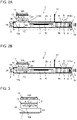
- FIG. 2A is a schematic cross-sectional view of the light irradiator according to the embodiment of the present disclosure.
- the directional terms such as up and down (or vertical) and right and left (or lateral) are used herein for clarity without limiting the structures or operating principles of the light irradiator and the printer.
- a light irradiator 1 illustrated in FIGs. 1 and 2A includes a light source 7 including multiple light emitters, a heat-dissipating member (heat sink) 9 thermally connected to the light source 7, a drive 11 including a drive circuit 10 for the light source 7, and a housing 2 that is configured to accommodate the light source 7, the heat-dissipating member 9, and the drive 11.
- the housing 2 includes multiple vents 4 (4a and 4b) and a light-emission opening 3 that allows light from the light source 7 to pass.
- the light irradiator 1 includes an axial fan 12 as a blower for blowing air to generate airflow into and out of the housing 2 through the vents 4 (4a and 4b).
- the axial fan 12 in the housing 2 is located at a second vent 4b to generate flow of the outside air (air) through a first vent 4a as an inlet and the second vent 4b as an outlet.
- the axial fan 12 is used for effective dissipation of heat from the heat-dissipating member 9 and the drive 11.
- the axial fan 12 with a small size can generate a large volume of airflow, and thus may be used to miniaturize and reduce the thickness of the light irradiator 1.
- the housing 2 includes a connector 6 on its surface opposite to the surface with the light-emission opening 3 in the longitudinal direction.
- the connector 6 is used to connect a wire to the drive 11 and direct the wire out of the housing 2.
- the drive 11 receives power from an external source and exchanges control signals with an external component through the connector 6.
- the drive circuit 10 in the drive 11 is electrically connected to the light source 7 with a light source substrate 8 in between with wiring members (not illustrated).
- the housing 2 is rectangular and includes a first surface 2a (the right end face in FIGs. 1 and 2A ) having a first side with a first dimension 2A and a second side with a second dimension 2B greater than the first dimension 2A, a second surface 2b (the top surface in FIGs. 1 and 2A ) having the second side and a third side with a third dimension 2C greater than the second dimension 2B, and a third surface 2c (the front lateral surface in FIG. 1 ) having the first side and the third side.
- the housing 2 includes the light-emission opening 3 in the first surface 2a, and the first vent 4a and the second vent 4b in the second surface 2b.
- the first vent 4a is nearer the light-emission opening 3 than the second vent 4b, and the second vent 4b is located opposite to the light-emission opening 3.
- the light source 7 is adjacent to the light-emission opening 3.
- the heat-dissipating member 9 faces the first vent 4a.
- the drive 11 is between the first vent 4a and the second vent 4b.
- the axial fan 12 is located at the second vent 4b.
- the housing 2 defines the profile of the light irradiator 1.
- the housing 2 is made of a metal such as aluminum or iron or a plastic.
- the housing 2 in the present embodiment is rectangular and includes the first surface 2a having the first side with the first dimension 2A and the second side with the second dimension 2B, the second surface 2b having the second side and the third side with the third dimension 2C, and the third surface 2c having the first side and the third side.
- the housing 2 includes the light-emission opening 3 in the first surface 2a to allow light from the light source 7 to be emitted outside.
- FIG. 2A illustrates three arrows on the right of the light-emission opening 3 to indicate light L being emitted.
- the housing 2 includes the vents 4 (4a and 4b) in the second surface 2b.
- the first vent 4a is nearer the light-emission opening 3 than the second vent 4b, and the second vent 4b is located opposite to the light-emission opening 3.
- the housing 2 has a thin rectangular profile and has dimensions determined as appropriate in accordance with the specifications of the light irradiator 1.
- the housing 2 has the first side with the first dimension 2A (corresponding to the thickness of the housing 2) of 20 to 40 mm, the second side with the second dimension 2B (corresponding to the width of the housing 2) of 80 to 120 mm, and the third side with the third dimension 2C (corresponding to the length of the housing 2) of 120 to 250 mm.
- the housing 2 is not limited to the above dimensions and may simply satisfy (first dimension 2A) ⁇ (second dimension 2B) ⁇ (third dimension 2C).
- the dimensions may be determined as appropriate for the use of the light irradiator 1.
- the light irradiator 1 is included in a printer such as a line printer that includes a printing unit including printheads with substantially the same width as the print medium.
- a printer such as a line printer that includes a printing unit including printheads with substantially the same width as the print medium.
- multiple light irradiators 1 may be arrayed to have substantially the same width as the print medium and have dimensions determined as appropriate for the array.
- the light irradiator 1 is used for temporarily curing ultraviolet curable inks in multiple colors printed on the print medium using multiple printheads. In this case, the light irradiator 1 is located in each small area between the printheads for the colors. Thus, the thickness of the housing 2 may be minimized.
- the light irradiator 1 may have a width corresponding to the width of each printhead (e.g., 120 mm) and can have the length with less restrictions.
- the light irradiator 1 may have the first dimension 2A (thickness) of about 20 mm, the second dimension 2B (width) of about 120 mm, and the third dimension 2C (length) of about 220 mm.
- the light irradiator 1 with such dimensions is thin and small.
- the housing 2 may not be precisely rectangular.
- the housing 2 may have the sides and corners rounded or chamfered as appropriate for its use and specifications.
- the first to third dimensions 2A to 2C may be defined as distances between two surfaces along the corresponding sides.
- the housing 2 includes the light-emission opening 3 in the first surface 2a to allow light from the light source 7 to be emitted outside to irradiate a target, such as a print medium.
- the light-emission opening 3 may be about 13 mm along the first dimension 2A.
- the light-emission opening 3 may be about 120 mm along the second dimension 2B.
- the light-emission opening 3 may extend across the first surface 2a of the housing 2 in the width direction (or the depth direction in FIG. 2A ) for miniaturizing the housing 2 and providing continuous radiation with multiple housings 2 arrayed adjacent to each other.
- the light-emission opening 3 may have any other structure.
- the light-emission opening 3 is typically rectangular in the same or similar manner to the first surface 2a. However, the light-emission opening 3 may have any of various shapes in accordance with the use, including the shape of waves, an ellipse, or multiple circles. The light-emission opening 3 may have any dimensions determined as appropriate within the dimensions of the first surface 2a in accordance with the use of the light irradiator 1.
- the light-emission opening 3 is typically located in the central portion including the center of the first surface 2a of the housing 2. However, the light-emission opening 3 may be open toward the light source 7 at a position offset from the center of the first surface 2a.
- the housing 2 may include a cover for the light-emission opening 3 as in the present embodiment. The cover may be made of a material that transmits light from the light source 7, such as glass or a heat-resistant plastic.
- the housing 2 includes the vents 4 in the second surface (top surface) 2b.
- the vents 4 allow air to flow into and out of the housing 2, or in other words, allow the outside air to flow into and out of the housing 2.
- the vents 4 include the first vent 4a and the second vent 4b in the second surface 2b. In the second surface 2b, the first vent 4a is nearer the light-emission opening 3 in the first surface 2a than the second vent 4b, and the second vent 4b is near an end opposite to the light-emission opening 3.
- the light irradiator 1 includes the heat-dissipating member (heat sink) 9 located opposite to the light-emission opening 3 from the light source 7 and thermally connected to the light source 7 in the housing 2.
- the heat-dissipating member 9 faces the first vent 4a.
- the heat-dissipating member 9 is on the left of the light source 7 and thermally connected to the light source 7 with the light source substrate 8 receiving the light source 7 in between.
- the housing 2 includes the drive 11 between the first vent 4a and the second vent 4b.
- the drive 11 includes the drive circuit 10.
- the axial fan 12, which is a blower, faces the second vent 4b.
- the housing 2 includes, near its both ends, the first vent 4a and the second vent 4b in the second surface 2b.
- the heat-dissipating member 9 faces the first vent 4a.
- the drive 11 is between the first vent 4a and the second vent 4b.
- the axial fan 12 faces the second vent 4b.
- the axial fan 12 blows air outside the housing 2 through the second vent 4b to cause smooth flow of air A from outside through the first vent 4a, the heat-dissipating member 9, the drive 11, and the second vent 4b and the axial fan 12, and then outside, as indicated by the broken line arrows in FIG. 2A .
- the thin and small light irradiator 1 can thus reduce heat from the light source 7.
- a space of at least substantially a quarter of a fan size 12A is typically to be left at the air intake of the axial fan 12.
- the fan size 12A is the outer size of the frame of the axial fan 12.
- the fan size 12A may be 40 mm for the axial fan 12 being a 40-mm square or a circle with a diameter of 40 mm.
- a space of substantially a quarter of 40 mm, or 10 mm is typically to be left at the intake of the axial fan 12.
- a thin light irradiator 1 as in the present embodiment may not allow a space of at least substantially a quarter of the fan size 12A to be left inside the housing 2, or specifically, at the air intake of the axial fan 12 at the second vent 4b in the housing 2. This may reduce the velocity and the volume of airflow from the axial fan 12 and may not allow the heat-dissipating member 9 to be maintained at an intended temperature of, for example, 60 °C, possibly causing the light emitters in the light source 7 to exceed a junction temperature of, for example, 125 °C at which the light emitter can operate stably.
- the axial fan 12 with the fan size 12A of 40 to 50 mm may use a space less than or equal to substantially a quarter of the fan size 12A at its intake.
- the axial fan 12 may generate exhaust airflow with a velocity decreasing to about 40 to 60% from the airflow defined by the specifications for the airflow using a space greater than substantially a quarter of the fan size 12A at the intake. This may disable the heat-dissipating member 9 from being maintained at an intended temperature.
- the inventor has noticed through studies that a first plate facing and adjacent to the outlet of the axial fan 12 can increase the velocity of exhaust airflow from the axial fan 12 by about 25 to 175%.
- This structure increases the velocity and the volume of airflow to achieve sufficient ventilation performance, thus maintaining the heat-dissipating member 9 at an intended temperature (specifically, for example, about 60 °C) when the thin housing 2 cannot have a sufficient space at the intake of the axial fan 12 and lowers the ventilation performance of the axial fan 12 below the level defined by the specifications of the axial fan 12.
- the light irradiator 1 according to the embodiment of the present disclosure is based on these findings.
- the axial fan 12 at the second vent 4b has the fan size 12A greater than the first dimension 2A and less than the second dimension 2B.
- the light irradiator 1 includes a first plate 13 opposite to the housing 2 from the axial fan 12.
- the first plate 13 faces the axial fan 12 with a spacing D1 less than or equal to the first dimension 2A between the first plate 13 and the axial fan 12.
- the spacing D1 is the distance between the axial fan 12 and the first plate 13.
- the inventor has noticed through studies that the first plate 13 can prevent a decrease in the velocity and the volume of airflow from the axial fan 12. In the light irradiator 1 including the thin housing 2, the axial fan 12 can thus generate airflow at an intended velocity and in an intended volume.
- the heat-dissipating member 9 can thus have an intended temperature of, for example, not higher than 60 °C.
- the light emitters in the light source 7 can have a junction temperature of, for example, not higher than 125 °C for a stable operation.
- the light irradiator 1 can thus operate stably for a long time.
- the first plate 13 may be any member that can serve as a baffle that obstructs the exhaust airflow from the axial fan 12.
- the first plate 13 may be made of any of various materials that can obstruct airflow and withstand heat from the exhaust airflow from the axial fan 12. Examples of the materials include various metals such as aluminum, iron, stainless steel, or copper, various plastics such as epoxy resins, phenolic resins, fluoropolymers, polycarbonates, or polypropene, or paper or wood, or any combination of these materials.
- FIG. 1 is a perspective view of the first plate 13 as viewed through.
- the first plate 13 may be transparent, semitransparent, or opaque.
- the first plate 13 may have the same or similar color to the housing 2 or the axial fan 12, or may have a different color.
- the first plate 13 may be placed using any of various components that do not provide excessive resistance to the exhaust airflow from the axial fan 12.
- the first plate 13 may be placed using spacers with any of various dimensions and shapes, such as rod-like, tubular, columnar, or plate-like spacers or using screws to support the first plate 13 from below.
- the first plate 13 may be placed using components fixed to the housing 2 to support the first plate 13 from above or laterally.
- the first plate 13 may basically have a size substantially equal to the fan size 12A of the axial fan 12 facing the first plate 13.
- the first plate 13 may have the same shape as or a similar shape to the axial fan 12.
- the first plate 13 may have the size adjusted to maintain performance.
- the first plate 13 may cover an area larger than the axial fan 12 or smaller than the area defined by the periphery of the axial fan 12.
- the first plate 13 may have any thickness.
- the first plate 13 may have a minimum thickness to reduce the thickness of the light irradiator 1 but may be relatively thick to increase strength and durability.
- a block that can serve as the first plate 13 may be used instead.
- the axial fan 12 is outside the housing 2 to be located at the second vent 4b.
- the axial fan 12 may be located inside the housing 2 through the second vent 4b, as illustrated in a cross-sectional view of FIG. 2B similar to FIG. 2A , or the axial fan 12 may be entirely inside the housing 2.
- FIG. 2B like reference numerals denote like components in FIG. 2A , and such components are not described.
- the axial fan 12 may extend across inside and outside the housing 2 at an intermediate position between the positions illustrated in FIGs. 2A and 2B .
- the axial fan 12 includes a surface 12a facing the internal space of the housing 2, and the surface 12a may be flush with the second surface 2b of the housing 2 or may be located inside the housing 2.
- the surface 12a of the axial fan 12 facing the internal space of the housing 2 and flush with the second surface 2b of the housing 2 the surface 12a is in the same plane as the second surface 2b, and the axial fan 12 is located outside the housing 2.
- the axial fan 12 extends across inside and outside the housing 2 or is located inside the housing 2.
- the light irradiator 1 including the axial fan 12 located partially or entirely inside the housing 2 can be thinner and smaller.
- the axial fan 12 located outside the housing 2 allows a greater space at the air intake of the axial fan 12 and thus may have higher performance.
- the light irradiator 1 includes the first plate 13 facing the axial fan 12 with the spacing D1 less than or equal to the first dimension 2A between the first plate 13 and the axial fan 12.
- the thin and small light irradiator 1 can thus improve the ventilation performance of the axial fan 12 that is likely to generate a small volume of air, and effectively cool the heat-dissipating member 9 and the light source 7 despite a limited space left at the air intake of the axial fan 12.
- the axial fan 12 may be separated from an inner surface 2d of the housing 2 facing the second vent 4b by a spacing D2 less than or equal to the first dimension 2A and less than or equal to substantially a quarter of the fan size 12A of the axial fan 12.
- the spacing D2 is less than or equal to the first dimension 2A
- the axial fan 12 is at least partially located inside the housing 2. With the spacing D1 between the first plate 13 and the axial fan 12, the light irradiator 1 with this structure including the first plate 13 facing the axial fan 12 can be thinner.
- the light irradiator 1 includes the first plate 13 facing the axial fan 12 with the spacing D1 between the first plate 13 and the axial fan 12. This increases the ventilation performance of the axial fan 12 and achieves intended cooling. The thin light irradiator 1 can thus operate stably for a long time.
- the spacing D2 is basically less than or equal to a quarter of the fan size 12A of the axial fan 12. However, this may slightly vary in accordance with the shapes and specifications of the components of the axial fan 12 or the shapes of the components around the axial fan 12 in the housing 2. With the boundary condition less strictly defined, the spacing D2 is to be less than or equal to substantially a quarter of the fan size 12A of the axial fan 12. In one example studied by the inventor, the fan size 12A was 40 mm, and the quarter is 10 mm. In this example, the airflow velocity decreased for the spacing D2 of 9 mm. The airflow velocity decreased greatly, by about 40%, for the spacing D2 of 8 mm.
- the first plate 13 was placed to face the axial fan 12 with the spacing D1 between the first plate 13 and the axial fan 12. The first plate 13 increased the airflow velocity by up to about 25% from the decreased velocity and maintained the heat-dissipating member 9 at an intended temperature of about 60 °C.
- the fan size 12A was 50 mm, and the quarter was 12.5 mm.
- the airflow velocity decreased for the spacing D2 of 12 and 11 mm. The airflow velocity decreased greatly, by about 60%, for the spacing D2 of 8 mm.
- the first plate 13 was placed to face the axial fan 12 with the spacing D1 between the first plate 13 and the axial fan 12. The first plate 13 increased the airflow velocity by up to about 175% from the decreased velocity and maintained the heat-dissipating member 9 at an intended temperature of about 60 °C.
- the housing 2 with the spacing D2 close to 0 mm obstructs airflow from the axial fan 12 and is impractical.
- the light irradiator 1 may thus be large enough to be practical while it is being miniaturized.
- the light irradiator 1 may thus have the spacing D2 of at least substantially one-eighth of the fan size 12A of the axial fan 12.
- the spacing D2 may be about 5 mm or greater, which is at least substantially one-eighth of the fan size.
- the spacing D2 may be about 6 mm or greater, which is at least substantially one-eighth of the fan size.
- FIG. 3 is a cross-sectional view of the main part describing the relationship between the spacing D1 and the spacing D2.
- the same reference numerals as in FIGs. 1 , 2A, and 2B are used.
- the spacing D2 less than or equal to substantially a quarter of the fan size 12A of the axial fan 12 can lower the ventilation performance of the axial fan 12
- the first plate 13 facing the axial fan 12 with the spacing D1 less than the spacing D2 between the first plate 13 and the axial fan 12 can increase the ventilation performance of the axial fan 12 to achieve intended cooling effectively.
- the airflow velocity decreased greatly, or by about 40%, with the spacing D2 of 8 mm as described above.
- the first plate 13 was placed with the spacing D1 of, for example, 7 to 3 mm, less than the spacing D2 to increase the airflow velocity by up to about 25% from the decreased velocity.
- the airflow velocity decreased greatly, or by about 60%, with the spacing D2 of 8 mm.
- the first plate 13 was placed with the spacing D1 of, for example, 7 to 3 mm, less than the spacing D2 to increase the airflow velocity by up to about 175% from the decreased velocity.
- the axial fan 12 extends parallel to the second surface 2b and the inner surface 2d of the housing 2 (or in other words, blows air orthogonally to the second surface 2b).
- the axial fan 12 may be inclined with its left portion downward in the figures.
- the inclined axial fan 12 allows air to efficiently flow out of the housing 2.
- the inclined axial fan 12 also sends air away from the light-emission opening 3 through the second vent 4b, thus allowing the print medium to be less susceptible to the airflow.
- the first vent 4a and the second vent 4b in the second surface 2b of the housing 2 may be at any of various positions or may have any shapes and sizes adjusted and determined as appropriate for the use and specifications of the light irradiator 1 and the specifications of the heat-dissipating member 9 and the axial fan 12.
- the second vent 4b, at which the axial fan 12 is located, may be about one to two times the size of the first vent 4a to allow efficient ventilation.
- two axial fans 12 are located at the second vent 4b in the housing 2.
- One or three or more axial fans 12 may be included in accordance with the specifications and the sizes of the light irradiator 1 and the housing 2.
- the light irradiator 1 includes a second plate 23 outside the housing 2 to separate the first vent 4a and the second vent 4b.
- the inventor has noticed that such a second plate 23 located outside the housing 2 can restore or improve the performance of the axial fan 12 in the light irradiator 1 with the spacing D1 and the spacing D2 both limited with respect to the axial fan 12.
- the ventilation through the housing 2 can also be affected by the airflow around the housing 2, as identified by the inventor through various experiments.
- the inventor has revealed that the exhaust airflow from the axial fan 12 from inside the housing 2 through the second vent 4b travels along the outer surface of the housing 2 to the first vent 4a and is sucked back into the housing 2 through the first vent 4a, generating airflow circulating between the second vent 4b and the first vent 4a. This can lower the ventilation performance of the axial fan 12, although the actual reason remains unknown. In contrast, as illustrated in FIGs.
- the second plate 23 outside the housing 2 to separate the first vent 4a and the second vent 4b can obstruct the airflow from the second vent 4b to the first vent 4a, thus reducing the decrease in the velocity of the exhaust airflow from the axial fan 12 and the decrease in the performance of the axial fan 12 in ventilating the housing 2.
- the second plate 23 may be at any position outside the housing 2 at which the second plate 23 separates the first vent 4a and the second vent 4b.
- the second plate 23 may be any member that can serve as a baffle that obstructs airflow from the second vent 4b to the first vent 4a.
- the second plate 23 may be made of any of various materials that can obstruct airflow and withstand heat of the exhaust airflow from the axial fan 12. Examples of such materials include various metals such as aluminum, iron, stainless steel, or copper, various plastics such as epoxy resins, ferrule resins, fluoropolymers, polycarbonates, or polypropene, or paper or wood, and any combination of the above materials.
- the second plate 23 may be transparent, translucent, or opaque.
- the second plate 23 may have the same or similar color to the housing 2 or the first plate 13, or may have a different color.
- the second plate 23 may be placed using any of various components including supports with any of various dimensions and shapes, such as rod-like, tubular, columnar, or plate-like supports or using screws to fix the second plate 23 to the housing 2.
- the second plate 23 may be fixed to the housing 2 with an adhesive, solder, or a brazing material.
- the second plate 23 may have any shape other than the plate in the embodiments illustrated in FIGs. 1 , 2A, and 2B .
- the second plate 23 may have any shape such as a curved, bent, or corrugated plate that obstructs the airflow from the second vent 4b to the first vent 4a in accordance with the specifications of the light irradiator 1.
- the second plate 23 extends outside the housing 2 in the direction intersecting with the direction linking the first vent 4a and the second vent 4b to separate the first vent 4a and the second vent 4b.
- the direction linking the first vent 4a and the second vent 4b may be, for example, the direction parallel to the straight line connecting the center of the first vent 4a and the center of the second vent 4b (or the center of any multiple first vents 4a across the first vents 4a and the center of any multiple second vents 4b across the second vents 4b).
- the direction intersecting with the linking direction may include, other than the direction orthogonal to the linking direction, any direction obliquely intersecting with the linking direction in which the second plate 23 obstructs the airflow between the first vent 4a and the second vent 4b outside the housing 2.
- the second plate 23 may have a width (dimension in the direction along the second side of the housing 2) greater than or equal to a narrower one of the widths of the first vent 4a and the second vent 4b (dimensions in the direction along the second side of the housing 2).
- the second plate 23 may have a width greater than or equal to the total width of the first vents 4a or the second vents 4b.
- the second plate 23 with such a width can effectively obstruct the airflow between the first vent 4a and the second vent 4b outside the housing 2.
- the second plate 23 may have a width greater than or equal to a wider one of the widths of the first vent 4a and the second vent 4b.
- the second plate 23 with such a width can effectively obstruct the airflow between the first vent 4a and the second vent 4b outside the housing 2.
- the second plate 23 may have a width less than or equal to the width of the light irradiator 1 (the second dimension 2B of the second side of the housing 2) for miniaturization of the light irradiator 1 and also for arranging multiple light irradiators 1.
- the width of the second plate 23 may be greater than the width of the light irradiator 1.
- multiple light irradiators 1 may be arrayed using the second plates 23 staggered in adjacent light irradiators 1 in the direction along the third side of the housing 2.
- the second plate 23 may have a height from the second surface 2b of the housing 2 (dimension in the direction along the first side of the housing 2) greater than or equal to a height to intersect with the straight line linking the end of the lower surface of the first plate 13 nearer the first vent 4a and the end of the first vent 4a nearer the second vent 4b.
- the second plate 23 having such a height can effectively obstruct the airflow exhausted from the axial fan 12 through the second vent 4b and directed to the first vent 4a by the lower surface of the first plate 13.
- the second plate 23 may have a height greater than or equal to the spacing between the first plate 13 and the housing 2 (the spacing between the lower surface of the first plate 13 and the second surface 2b of the housing 2 or the height from the second surface 2b of housing 2 to the lower surface of the first plate 13).
- the second plate 23 with such a height can effectively obstruct the airflow from the second vent 4b to the first vent 4a outside the housing 2.
- the height of the second plate 23 may have an upper limit set as appropriate to reflect the intended size of a smaller light irradiator 1 and the space limitations in the printer to incorporate the light irradiator 1.
- the second plate 23 has a constant height across the width, but may have its height varying across the width.
- the airflow from the second vent 4b to the first vent 4a may be obstructed with the second plate 23 that is partially higher in the middle portion or end portions, or partially higher in a portion in which the second plate 23 intersects with the straight line linking the center of the first vent 4a and the center of each of multiple second vents 4b.
- the second plate 23 may have any thickness.
- a thin second plate 23 that can obstruct the airflow from the second vent 4b to the first vent 4a may be used to reduce the weight of the light irradiator 1.
- the second plate 23 may be relatively thick to increase its strength and durability.
- the second plate 23 may be replaced with a thick block that provides the capability of the second plate 23.
- a thick second plate 23 may be integral with the housing 2.
- the housing 2 may be shaped to include a partially protruding second surface.
- the second plate 23 outside the housing 2, or more specifically, on the second surface 2b of the housing 2 may be at any position between the first vent 4a and the second vent 4b.
- the second plate 23 may be nearer the first vent 4a as an inlet, rather than nearer the second vent 4b as an outlet.
- the second plate 23 nearer the second vent 4b can increase the resistance of the exhaust airflow depending on the relationship with the first plate 13. Such inconvenience is to be avoided.
- the second plate 23 nearer the first vent 4a effectively obstructs the airflow from the second vent 4b to the first vent 4a.
- the second plate 23 may be near the first vent 4a. In the embodiments illustrated in FIGs. 1 , 2A, and 2B , the second plate 23 is near the first vent 4a.
- the second plate 23 may be near the first vent 4a as appropriate in accordance with the specifications of the light irradiator 1.
- the second plate 23 near the first vent 4a as an inlet effectively obstructs the airflow from the second vent 4b to the first vent 4a.
- the second plate 23 may have a height greater than or equal to a height to intersect with the straight line linking the end of the lower surface of the first plate 13 nearer the first vent 4a and the end of the first vent 4a nearer the second vent 4b as described above, the second plate 23 near the first vent 4a as an inlet may have a height that is too low and is impractical.
- the second plate 23 may thus have a height greater than or equal to the height described above and to obstruct the airflow from the second vent 4b to the first vent 4a.
- the second plate 23 having a height greater than or equal to the spacing between the first plate 13 and the housing 2 effectively obstructs the airflow from the second vent 4b to the first vent 4a.
- the first plate 13 placed with the spacing D1 of, for example, 7 to 3 mm that is less than the spacing D2 of 8 mm increases the airflow velocity by up to about 25% from the velocity decreasing greatly by about 40%.
- the second plate 23 further increases the airflow velocity by up to about 10%, effectively maintaining the heat-dissipating member 9 at an intended temperature of about 60 °C.
- the first plate 13 placed with the spacing D1 of, for example, 7 to 3 mm that is less than the spacing D2 of 8 mm increases the airflow velocity by up to about 175% from the velocity decreasing greatly by about 60%.
- the second plate 23 further increases the airflow velocity by up to about 15%, effectively maintaining the heat-dissipating member 9 at an intended temperature of about 60 °C.
- the housing 2 includes the light source 7 facing the light-emission opening 3 in the first surface 2a.
- the light source 7 may include, for example, a matrix array of LEDs on the light source substrate 8.
- the light source 7 may include GaN LEDs that emit ultraviolet rays. In another embodiment, the light source 7 may include GaAs LEDs that emit infrared rays.
- the light source 7 may be selectable in accordance with the wavelength to be used.
- the light source substrate 8 may be, for example, a ceramic wiring board.
- the ceramic wiring board includes a ceramic base (insulating substrate), which resists heat. Thus, the ceramic wiring board may be used as the light source substrate 8 for the light source 7 that includes LEDs generating heat.
- the heat-dissipating member 9 dissipates heat resulting from light emission from the light source 7.
- the heat-dissipating member 9 is thermally connected to the light source 7.
- the heat-dissipating member 9 is made of a thermally conductive metal, such as aluminum or copper.
- the heat-dissipating member 9 may be formed by cutting a rectangular block of aluminum or copper to form multiple channels (with the remaining parts serving as fins) to increase the surface area.
- the heat-dissipating member 9 includes multiple sheets of aluminum or copper attached to a metal plate or block made of aluminum or copper to serve as fins, between which outside air flows.
- the heat-dissipating member 9 may occupy, in the housing 2, a space extending in the direction along the first side (along the first dimension 2A) of the first surface 2a.
- the heat-dissipating member 9 may include a recess 9a recessed in the direction along the first side and facing the first vent 4a in the second surface 2b.
- the recess 9a can accommodate a filter 5 to face the first vent 4a.
- the filter 5 to reduce dust or other matter entering the housing 2 can be arranged in a space-efficient manner to achieve a thinner light irradiator 1.
- the heat-dissipating member 9 occupying, in the housing 2, a space extending in the direction along the first side is not limited to the heat-dissipating member 9 fully occupying the space between the inner surface of the housing 2 adjacent to the second surface 2b and the inner surface opposite to this inner surface.
- the heat-dissipating member 9 may substantially occupy a major part of the space with clearances left in the direction along the first side.
- the housing 2 may include clearances around the heat-dissipating member 9 for attachment or detachment or for accommodating thermal expansion.
- the recess 9a may not face the entire first vent 4a.
- the recess 9a may have dimensions to partially face the first vent 4a and fit in the first vent 4a.
- the recess 9a may be larger than and extend beyond the first vent 4a, or extend across inside and outside the first vent 4a.
- the recess 9a may have any depth determined as appropriate for the shape and size of the filter 5.
- the filter 5 may include, for example, a sponge or a nonwoven fabric.
- the filter 5 prevents foreign matter such as dust and dirt in outside air from entering the housing 2 and thus prevents the efficiency of the heat dissipation from the light source 7 or the drive 11 from decreasing due to such dust and dirt accumulating on the heat-dissipating member 9 or the drive 11. This improves the reliability of the light irradiator 1.
- the filter 5 also decelerates the flow of outside air around the vent 4.
- the filter 5 may have about a 1 mm greater width and a 1 mm greater length than the first vent 4a, and may have a thickness of about 1 mm.
- the recess 9a may have the same shape as the filter 5. The filter 5 thus allows passage of all the incoming air entering through the first vent 4a, thus reliably removing foreign matter from the incoming air.
- the filter 5 is received in the recess 9a to face the first vent 4a and in contact with the fins in the heat-dissipating member 9, allowing passage of all the incoming air entering through the first vent 4a between the fins in the heat-dissipating member 9 for efficient heat dissipation.
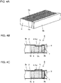
- the heat-dissipating member 9 illustrated in FIGs. 4A and 4B includes a metal block 9b with multiple metal sheets 9c attached as fins.
- the sheets 9c include cutouts having the same shapes and sizes in their upper portions in the figures.
- the cutouts and the block 9b define the recess 9a.
- the recess 9a may have any other structure.
- the filter 5 may be attached in a different manner, without using the recess 9a in the heat-dissipating member 9.
- the heat-dissipating member 9 in the housing 2 may include no recess as illustrated in a schematic partial cross-sectional view of FIG. 4C similar to FIG. 4B .
- the housing 2 may include the filter 5 facing the first bent 4a located outside the first vent 4a.
- the filter 5 may be covered with a frame.
- the heat-dissipating member 9 may be connected to the light source substrate 8 with, for example, thermal grease.
- the grease increases the adhesion between the heat-dissipating member 9 and the light source substrate 8 to improve the thermal connection. This improves the efficiency of heat dissipation from the light source 7.
- the light irradiator 1 includes the drive (drive board) 11 in the housing 2.
- the drive 11 is electrically connected to the light source 7 to drive the light source 7.
- the drive 11 includes the drive circuit 10 for supplying power to the light source 7 and controlling light emission.
- the drive 11 may also drive the axial fan 12 as a blower and control the rotational speed of the axial fan 12 in accordance with heat generation from the light source 7.
- the drive 11 including the drive circuit 10 generates heat in driving the light source 7 or controlling the axial fan 12. Such heat is to be appropriately dissipated for cooling.
- the drive 11 may include a heat-dissipating member, such as a heat sink, for dissipating heat from electronic components such as power transistors that easily reach high temperatures in, for example, the drive circuit 10.
- the housing 2 may include channels, fins, an air deflector, or other components on the inner surface around the drive 11 to allow the outside air to effectively flow to parts of the drive 11 that easily reach high temperatures.
- the drive 11 is typically a drive board including a wiring board.
- the drive circuit 10 is typically a drive circuit board including a wiring board.
- the drive 11 in the housing 2 may be adjacent to the second surface 2b including the first and second vents 4a and 4b with the drive circuit 10 facing the internal space of the housing 2.
- the drive 11 in the housing 2 may be nearer the inner surface adjacent to the second surface 2b including the first and second vents 4a and 4b in the direction along the first side with the first dimension 2A.
- the drive 11 may receive the drive circuit 10 facing the internal space of the housing 2, or in other words, facing the surface without the first and second vents 4a and 4b.
- a passage of the outside air, entering through the first vent 4a and flowing through the heat-dissipating member 9 to the axial fan 12, is effectively defined by the drive 11 between the heat-dissipating member 9 and the axial fan 12 in the housing 2 and by the inner surface of the housing 2 opposite to the second surface 2b including the vents 4.
- the drive circuit 10 can be located in the passage of the outside air in the housing 2 to allow efficient dissipation of heat from the drive circuit 10 and the drive 11. This improves the operational stability of the drive circuit 10 and the drive 11 and the reliability of the light irradiator 1.
- the drive 11 may be fastened with, for example, screws with a base, a support, or a spacer placed as appropriate between the drive 11 and one or both of the inner surface of the housing 2 adjacent to the second surface 2b and the inner surface opposite to this inner surface.
- the housing 2 includes a relatively large space between the drive 11 and the inner surfaces, and thus allows relatively flexible positioning of the fastening portions.
- the drive 11 may be fastened to one or both of the inner surfaces adjacent to the pair of third surfaces 2c of the housing 2 as appropriate with fasteners.
- the drive 11 in the housing 2 may be nearer the inner surface opposite to the second surface 2b including the first and second vents 4a and 4b in the direction along the first side with the first dimension 2A.
- the drive 11 may receive the drive circuit 10 facing the internal space of the housing 2, or in other words, facing the surface with the first and second vents 4a and 4b.
- a passage of the outside air, entering through the first vent 4a and flowing through the heat-dissipating member 9 to the axial fan 12 is effectively defined by the drive 11 between the heat-dissipating member 9 and the axial fan 12 in the housing 2 and by the inner surface of the housing 2 adjacent to the second surface 2b including the vents 4.
- the drive circuit 10 can be located in the passage of the outside air in the housing 2 to allow efficient dissipation of heat from the drive circuit 10 and the drive 11.
- the drive circuit 10 in the drive 11 is electrically connected to the light source 7 with the light source substrate 8 in between using wiring members.
- An example of the wiring members is illustrated in a partial perspective view of FIG. 5.
- FIG. 5 does not illustrate a part of the second surface 2b of the housing 2 to illustrate the drive 11.
- the light irradiator 1 in the embodiment illustrated in FIG. 5 includes FPCs (flexible printed circuits) as wiring members 14 electrically connecting the drive 11 to a light source (not illustrated) facing the light-emission opening 3 in the housing 2.
- the FPCs include multiple wires and may carry a relatively high current.
- the FPCs, which serve as the flexible wiring members 14, may also be routed in the housing 2. As illustrated in FIG.
- the wiring members 14 using FPCs extend from the light source and the light source substrate (not illustrated) thermally connected to the heat-dissipating member 9.
- the wiring members 14 further extend along the heat-dissipating member 9 without passing through the heat-dissipating member 9.
- the wiring members 14 are raised for electrical connection to the drive 11 after passing the heat-dissipating member 9.
- Components 16 are board-to-FPC connectors that connect the wiring members 14 to the drive 11.
- the wiring members 14 using flexible FPCs are generally thin and wide.
- the wiring members 14 include portions raised toward the drive 11, which may obstruct the airflow through the heat-dissipating member 9 to the axial fan 12 in the housing 2 generated by the axial fan 12.
- the flexible wiring members 14 connecting the light source to the drive 11 may include multiple wires extending along the heat-dissipating member 9, and the wiring members 14 may include slits 15 between the wires in an area of airflow generated by the axial fan 12.
- Each wiring member 14 may include multiple slits 15.
- the wiring members 14 with the slits 15 avoid obstructing air flowing through the heat-dissipating member 9, thus reducing the decrease in the heat dissipation efficiency.
- the flexible wiring members 14 may extend along the heat-dissipating member 9.
- the wiring members 14 have portions along the heat-dissipating member 9 between the heat-dissipating member 9 and the inner surface of the housing 2 and portions raised toward the drive 11. These portions may extend in direct contact with or slightly away from the heat-dissipating member 9.
- the wiring members 14 extending in direct contact with the heat-dissipating member 9 may save space.
- the wiring members 14 extending slightly away from the heat-dissipating member 9 may reduce obstruction of airflow.
- the wiring members 14 and the drive 11 may be effectively protected against heat.
- the wiring members 14 may have any layout with the slits 15 at any location and with any shape and size as appropriate for the design for appropriate airflow through the housing 2.
- FIG. 6 is a schematic front view of a printer according to the embodiment of the present disclosure.
- a printer 100 according to the embodiment illustrated in FIG. 6 includes the light irradiator 1 according to the embodiment of the present disclosure, a feeder 120 for feeding a print medium 110 to be irradiated with light emitted from the light irradiator 1 through the light-emission opening 3, and a printing unit 130 upstream from the light irradiator 1 in the feed direction of the print medium 110 to print on the print medium 110 being fed.
- the printing unit 130 includes IJ (inkjet) heads that use, for example, ultraviolet curable inks.
- the printer 100 with this structure includes the thin and small light irradiator 1 located near the printing unit 130.
- the light irradiator 1 causes the outside air (air) to flow in through the first vent 4a and out through the second vent 4b.
- the light irradiator 1 allows the printing unit 130 and the print medium 110 to be less susceptible to the airflow when irradiating the printed print medium 110.
- the printer 100 is small and reliable.
- the feeder 120 feeds the print medium 110 from right to left in the figure.
- the feeder 120 in the present embodiment includes pairs of drive rollers upstream and downstream in the feed direction.
- a support for supporting the print medium 110 being fed may be provided near or integral with the feeder 120.
- the printing unit 130 ejects, for example, an ultraviolet curable ink 131 onto the print medium 110 being fed and deposits the ink 131 onto the surface of the print medium 110.
- the ink 131 may be deposited entirely or partially onto the surface of the print medium 110 with any pattern as intended.
- the light irradiator 1 irradiates the ultraviolet curable ink 131 on the print medium 110 with ultraviolet rays to cure the ink 131.
- the photosensitive material used in the present embodiment is the ultraviolet curable ink 131.
- the photosensitive material in another embodiment may be a photoresist or a photocurable resin.
- the light irradiator 1 is connected to a controller 140 for controlling light emission from the light irradiator 1.
- the controller 140 includes an internal memory storing information indicating the properties of light relatively suitable for curing a photocurable ink 131 to be ejected from the IJ heads as the printing unit 130.
- Examples of the stored information include numerical values representing the wavelength distribution characteristics and the emission intensities (the emission intensity for each wavelength range) suitable for curing the ink 131 to be ejected in droplets.
- the controller 140 also adjusts the level of the drive current to be input into the multiple light emitters in the light source 7 based on the information stored in the controller 140.
- the light irradiator 1 in the printer 100 thus emits an appropriate amount of light in accordance with the characteristics of the ink used. This allows the ink 131 to be cured with relatively low-energy light.
- the printing unit 130 in the present embodiment includes line IJ heads.
- the IJ heads 130 each include multiple ink ejection nozzles linearly arrayed to eject, for example, an ultraviolet curable ink.
- the IJ heads as the printing unit 130 print the print medium 110 by ejecting ink from the ejection nozzles and depositing the ink 131 onto the print medium 110 being fed in a direction orthogonal to the array of ejection nozzles in the depth direction.
- the printing unit 130 is not limited to the line IJ heads.
- the printing unit 130 may include serial IJ heads.
- the printing unit 130 may include electrostatic heads that electrostatically deposit a developer (toner) onto the print medium 110 charged with static electricity.
- the printing unit 130 may include a liquid developing device in which the print medium 110 is immersed in a liquid developer or toner to deposit the toner onto the print medium 110.
- the printing unit 130 may include a brush or a roller for feeding a developer (toner).
- the light irradiator 1 may include the first surface 2a elongated in the depth direction in the figure in accordance with the width of the print medium 110. In some embodiments, multiple light irradiators 1 may be arrayed in the depth direction in the figure in accordance with the width of the print medium 110.
- the light irradiator 1 cures a photocurable ink 131, or exposes a photosensitive ink 131 to light on the print medium 110 being fed by the feeder 120.
- the light irradiator 1 is downstream from the printing unit 130 in the feed direction of the print medium 110.
- the printer 100 in the present embodiment may use an ink 131 other than the ultraviolet curable ink 131.
- the printer 100 may print a water- or oil-based ink 131 on the print medium 110 using the IJ heads as the printing unit 130, and irradiate the print medium 110 with infrared rays using the light irradiator 1 to dry and fix the ink 131 with the heat.
- the printer 100 may use any printing method, as well as inkjet printing, that can fix the ink 131 on the print medium 110 with infrared rays.
- the light irradiator 1 in the present embodiment is included in the printer 100 that uses the IJ heads as the printing unit 130.
- the light irradiator 1 may be included in one of various resin curing systems, including a system for applying a paste containing a photosensitive resin (e.g., a resist) to a target surface with spin coating or screen printing and then curing the coated or printed photosensitive resin.
- the light irradiator 1 may be used as a light source in an exposure system that exposes, for example, a resist to light.
Landscapes
- Health & Medical Sciences (AREA)
- General Health & Medical Sciences (AREA)
- Toxicology (AREA)
- Physics & Mathematics (AREA)
- General Physics & Mathematics (AREA)
- Supply, Installation And Extraction Of Printed Sheets Or Plates (AREA)
- Coating Apparatus (AREA)
- Ink Jet (AREA)
- Arrangement Of Elements, Cooling, Sealing, Or The Like Of Lighting Devices (AREA)
- Cooling Or The Like Of Electrical Apparatus (AREA)
- Accessory Devices And Overall Control Thereof (AREA)
- Exposure And Positioning Against Photoresist Photosensitive Materials (AREA)
Abstract
Description
- The present disclosure relates to a light irradiator and a printer including the light irradiator.
- A light irradiator includes a light source and a drive board for driving the light source both accommodated in a housing. Examples of the light source include lamps or LEDs (light-emitting diodes) that emit ultraviolet rays or infrared rays. Such light irradiators are commonly used in healthcare including sterilization, assembly production including curing of adhesives or ultraviolet curable resins in electronic packaging, drying including irradiation of targets with infrared rays for efficient drying, and printing including drying or curing of inks.
- Among different purposes, light irradiators for printing are designed for higher output of light for recent faster printing and are also to be miniaturized for space-saving.
- A light source included in a light irradiator generates heat when emitting light. The light source emitting more light may generate more heat. To effectively dissipate heat and also miniaturize the light irradiator, the light irradiator may further include a heat sink (heat-dissipating member) thermally connected to the light source and accommodated together in the housing (refer to, for example,
Japanese Registered Utility Model Nos. 3190306 3196411 - In an aspect of the present disclosure, a light irradiator includes a light source including a plurality of light emitters, a heat-dissipating member thermally connected to the light source, a drive including a drive circuit for the light source, and a housing that is configured to accommodate the light source, the heat-dissipating member, and the drive. The housing includes a plurality of vents and a light-emission opening to allow light from the light source to pass. The housing is rectangular and includes a first surface having a first side with a first dimension and a second side with a second dimension greater than the first dimension, a second surface having the second side and a third side with a third dimension greater than the second dimension, and a third surface having the first side and the third side. The light-emission opening is in the first surface. A first vent and a second vent are in the second surface. The first vent is nearer the light-emission opening than the second vent. The second vent is located opposite to the light-emission opening. The light source is adjacent to the light-emission opening. The heat-dissipating member faces the first vent. The drive is between the first vent and the second vent. The light irradiator includes an axial fan at the second vent. The axial fan blows air from inside the housing to outside. The axial fan has a fan size greater than the first dimension and less than the second dimension. The light irradiator includes a first plate at the second vent. The first plate faces the axial fan with a spacing less than or equal to the first dimension between the first plate and the axial fan. The light irradiator includes a second plate outside the housing. The second plate separates the first vent and the second vent.
- In another aspect of the present disclosure, a printer includes the light irradiator according to the above aspect of the present disclosure, a feeder that feeds a print medium to be irradiated with light emitted from the light irradiator through the light-emission opening, and a printing unit upstream from the light irradiator in a feed direction of the print medium.
-
-
FIG. 1 is a schematic perspective view of a light irradiator according to an embodiment of the present disclosure. -
FIG. 2A is a schematic cross-sectional view of the light irradiator according to the embodiment of the present disclosure, andFIG. 2B is a schematic cross-sectional view of a light irradiator according to another embodiment of the present disclosure. -
FIG. 3 is a cross-sectional view of an axial fan and a first plate for the light irradiator according to the embodiment of the present disclosure, describing the spacings between the axial fan and the first plate and between the axial fan and a housing. -
FIG. 4A is a perspective view of a heat-dissipating member for the light irradiator according to the embodiment of the present disclosure,FIG. 4B is a schematic partial cross-sectional view of the light irradiator according to the embodiment of the present disclosure, andFIG. 4C is a schematic partial cross-sectional view of a light irradiator according to another embodiment. -
FIG. 5 is a schematic partial perspective view of the light irradiator according to the embodiment of the present disclosure. -
FIG. 6 is a schematic front view of a printer according to an embodiment of the present disclosure. - A light irradiator may include, as well as a light source, a drive, a blower, and a heat-dissipating member such as a heat sink, all accommodated in a single housing. Such a light irradiator may not achieve miniaturization and sufficient heat dissipation at the same time.
- In particular, a light irradiator included in a printer may be designed thinner for miniaturization. More specifically, the light irradiator may be generally rectangular and have a large width in the width direction of a print medium being fed, a small thickness in the feed direction, and a length in the direction orthogonal to the print medium larger than the width and the thickness. However, such a thin light irradiator may fail to include an effective passage of air flowing into and out of the housing for cooling the light source.
- A thin, small, and high-output light irradiator that can efficiently cool the light source is awaited.
- A light irradiator according to one or more embodiments of the present disclosure efficiently cools the light source with an axial fan and is also thin and small, and has improved light output.
- A printer according to one or more embodiments of the present disclosure includes the thin and small light irradiator with improved cooling performance according to one or more embodiments of the present disclosure. The printer is thus small and efficient.
- A light irradiator and a printer according to one or more embodiments of the present disclosure will now be described with reference to the drawings.
-
FIG. 1 is a schematic perspective view of a light irradiator according to an embodiment of the present disclosure.FIG. 2A is a schematic cross-sectional view of the light irradiator according to the embodiment of the present disclosure. The directional terms such as up and down (or vertical) and right and left (or lateral) are used herein for clarity without limiting the structures or operating principles of the light irradiator and the printer. - A
light irradiator 1 illustrated inFIGs. 1 and2A includes alight source 7 including multiple light emitters, a heat-dissipating member (heat sink) 9 thermally connected to thelight source 7, adrive 11 including adrive circuit 10 for thelight source 7, and ahousing 2 that is configured to accommodate thelight source 7, the heat-dissipatingmember 9, and thedrive 11. Thehousing 2 includes multiple vents 4 (4a and 4b) and a light-emission opening 3 that allows light from thelight source 7 to pass. Thelight irradiator 1 includes anaxial fan 12 as a blower for blowing air to generate airflow into and out of thehousing 2 through the vents 4 (4a and 4b). - The
axial fan 12 in thehousing 2 is located at asecond vent 4b to generate flow of the outside air (air) through afirst vent 4a as an inlet and thesecond vent 4b as an outlet. Theaxial fan 12 is used for effective dissipation of heat from the heat-dissipatingmember 9 and thedrive 11. Theaxial fan 12 with a small size can generate a large volume of airflow, and thus may be used to miniaturize and reduce the thickness of thelight irradiator 1. - The
housing 2 includes aconnector 6 on its surface opposite to the surface with the light-emission opening 3 in the longitudinal direction. Theconnector 6 is used to connect a wire to thedrive 11 and direct the wire out of thehousing 2. Thedrive 11 receives power from an external source and exchanges control signals with an external component through theconnector 6. Thedrive circuit 10 in thedrive 11 is electrically connected to thelight source 7 with alight source substrate 8 in between with wiring members (not illustrated). - The
housing 2 is rectangular and includes afirst surface 2a (the right end face inFIGs. 1 and2A ) having a first side with afirst dimension 2A and a second side with asecond dimension 2B greater than thefirst dimension 2A, asecond surface 2b (the top surface inFIGs. 1 and2A ) having the second side and a third side with a third dimension 2C greater than thesecond dimension 2B, and athird surface 2c (the front lateral surface inFIG. 1 ) having the first side and the third side. Thehousing 2 includes the light-emission opening 3 in thefirst surface 2a, and thefirst vent 4a and thesecond vent 4b in thesecond surface 2b. Thefirst vent 4a is nearer the light-emission opening 3 than thesecond vent 4b, and thesecond vent 4b is located opposite to the light-emission opening 3. Thelight source 7 is adjacent to the light-emission opening 3. The heat-dissipatingmember 9 faces thefirst vent 4a. Thedrive 11 is between thefirst vent 4a and thesecond vent 4b. Theaxial fan 12 is located at thesecond vent 4b. - The
housing 2 defines the profile of thelight irradiator 1. Thehousing 2 is made of a metal such as aluminum or iron or a plastic. Thehousing 2 in the present embodiment is rectangular and includes thefirst surface 2a having the first side with thefirst dimension 2A and the second side with thesecond dimension 2B, thesecond surface 2b having the second side and the third side with the third dimension 2C, and thethird surface 2c having the first side and the third side. Thehousing 2 includes the light-emission opening 3 in thefirst surface 2a to allow light from thelight source 7 to be emitted outside.FIG. 2A illustrates three arrows on the right of the light-emission opening 3 to indicate light L being emitted. Thehousing 2 includes the vents 4 (4a and 4b) in thesecond surface 2b. Thefirst vent 4a is nearer the light-emission opening 3 than thesecond vent 4b, and thesecond vent 4b is located opposite to the light-emission opening 3. - The
housing 2 has a thin rectangular profile and has dimensions determined as appropriate in accordance with the specifications of thelight irradiator 1. For example, thehousing 2 has the first side with thefirst dimension 2A (corresponding to the thickness of the housing 2) of 20 to 40 mm, the second side with thesecond dimension 2B (corresponding to the width of the housing 2) of 80 to 120 mm, and the third side with the third dimension 2C (corresponding to the length of the housing 2) of 120 to 250 mm. Thehousing 2 is not limited to the above dimensions and may simply satisfy (first dimension 2A) < (second dimension 2B) < (third dimension 2C). The dimensions may be determined as appropriate for the use of thelight irradiator 1. In one embodiment, thelight irradiator 1 is included in a printer such as a line printer that includes a printing unit including printheads with substantially the same width as the print medium. In this case, multiplelight irradiators 1 may be arrayed to have substantially the same width as the print medium and have dimensions determined as appropriate for the array. In another embodiment, thelight irradiator 1 is used for temporarily curing ultraviolet curable inks in multiple colors printed on the print medium using multiple printheads. In this case, thelight irradiator 1 is located in each small area between the printheads for the colors. Thus, the thickness of thehousing 2 may be minimized. Thelight irradiator 1 may have a width corresponding to the width of each printhead (e.g., 120 mm) and can have the length with less restrictions. Thus, thelight irradiator 1 may have thefirst dimension 2A (thickness) of about 20 mm, thesecond dimension 2B (width) of about 120 mm, and the third dimension 2C (length) of about 220 mm. Thelight irradiator 1 with such dimensions is thin and small. Thehousing 2 may not be precisely rectangular. Thehousing 2 may have the sides and corners rounded or chamfered as appropriate for its use and specifications. In this case, the first tothird dimensions 2A to 2C may be defined as distances between two surfaces along the corresponding sides. - The
housing 2 includes the light-emission opening 3 in thefirst surface 2a to allow light from thelight source 7 to be emitted outside to irradiate a target, such as a print medium. When thehousing 2 has thefirst dimension 2A (thickness) of about 20 mm as described above, the light-emission opening 3 may be about 13 mm along thefirst dimension 2A. When thehousing 2 has thesecond dimension 2B of about 120 mm as described above, the light-emission opening 3 may be about 120 mm along thesecond dimension 2B. The light-emission opening 3 may extend across thefirst surface 2a of thehousing 2 in the width direction (or the depth direction inFIG. 2A ) for miniaturizing thehousing 2 and providing continuous radiation withmultiple housings 2 arrayed adjacent to each other. However, the light-emission opening 3 may have any other structure. - The light-
emission opening 3 is typically rectangular in the same or similar manner to thefirst surface 2a. However, the light-emission opening 3 may have any of various shapes in accordance with the use, including the shape of waves, an ellipse, or multiple circles. The light-emission opening 3 may have any dimensions determined as appropriate within the dimensions of thefirst surface 2a in accordance with the use of thelight irradiator 1. The light-emission opening 3 is typically located in the central portion including the center of thefirst surface 2a of thehousing 2. However, the light-emission opening 3 may be open toward thelight source 7 at a position offset from the center of thefirst surface 2a. Thehousing 2 may include a cover for the light-emission opening 3 as in the present embodiment. The cover may be made of a material that transmits light from thelight source 7, such as glass or a heat-resistant plastic. - The
housing 2 includes thevents 4 in the second surface (top surface) 2b. Thevents 4 allow air to flow into and out of thehousing 2, or in other words, allow the outside air to flow into and out of thehousing 2. Thevents 4 include thefirst vent 4a and thesecond vent 4b in thesecond surface 2b. In thesecond surface 2b, thefirst vent 4a is nearer the light-emission opening 3 in thefirst surface 2a than thesecond vent 4b, and thesecond vent 4b is near an end opposite to the light-emission opening 3. - The
light irradiator 1 includes the heat-dissipating member (heat sink) 9 located opposite to the light-emission opening 3 from thelight source 7 and thermally connected to thelight source 7 in thehousing 2. The heat-dissipatingmember 9 faces thefirst vent 4a. In the embodiment illustrated inFIG. 2A , the heat-dissipatingmember 9 is on the left of thelight source 7 and thermally connected to thelight source 7 with thelight source substrate 8 receiving thelight source 7 in between. Thehousing 2 includes thedrive 11 between thefirst vent 4a and thesecond vent 4b. Thedrive 11 includes thedrive circuit 10. Theaxial fan 12, which is a blower, faces thesecond vent 4b. - The
housing 2 includes, near its both ends, thefirst vent 4a and thesecond vent 4b in thesecond surface 2b. The heat-dissipatingmember 9 faces thefirst vent 4a. Thedrive 11 is between thefirst vent 4a and thesecond vent 4b. Theaxial fan 12 faces thesecond vent 4b. Theaxial fan 12 blows air outside thehousing 2 through thesecond vent 4b to cause smooth flow of air A from outside through thefirst vent 4a, the heat-dissipatingmember 9, thedrive 11, and thesecond vent 4b and theaxial fan 12, and then outside, as indicated by the broken line arrows inFIG. 2A . This reduces stagnant air in thehousing 2 and efficiently dissipates heat and cools the heat-dissipatingmember 9 and thedrive 11. The thin and smalllight irradiator 1 can thus reduce heat from thelight source 7. - To generate a sufficient volume of airflow during operation, a space of at least substantially a quarter of a
fan size 12A is typically to be left at the air intake of theaxial fan 12. Thefan size 12A is the outer size of the frame of theaxial fan 12. Thefan size 12A may be 40 mm for theaxial fan 12 being a 40-mm square or a circle with a diameter of 40 mm. For the square or circularaxial fan 12 having thefan size 12A of 40 mm, a space of substantially a quarter of 40 mm, or 10 mm, is typically to be left at the intake of theaxial fan 12. However, athin light irradiator 1 as in the present embodiment may not allow a space of at least substantially a quarter of thefan size 12A to be left inside thehousing 2, or specifically, at the air intake of theaxial fan 12 at thesecond vent 4b in thehousing 2. This may reduce the velocity and the volume of airflow from theaxial fan 12 and may not allow the heat-dissipatingmember 9 to be maintained at an intended temperature of, for example, 60 °C, possibly causing the light emitters in thelight source 7 to exceed a junction temperature of, for example, 125 °C at which the light emitter can operate stably. - For example, the
axial fan 12 with thefan size 12A of 40 to 50 mm may use a space less than or equal to substantially a quarter of thefan size 12A at its intake. In this case, theaxial fan 12 may generate exhaust airflow with a velocity decreasing to about 40 to 60% from the airflow defined by the specifications for the airflow using a space greater than substantially a quarter of thefan size 12A at the intake. This may disable the heat-dissipatingmember 9 from being maintained at an intended temperature. - The inventor has noticed through studies that a first plate facing and adjacent to the outlet of the
axial fan 12 can increase the velocity of exhaust airflow from theaxial fan 12 by about 25 to 175%. This structure increases the velocity and the volume of airflow to achieve sufficient ventilation performance, thus maintaining the heat-dissipatingmember 9 at an intended temperature (specifically, for example, about 60 °C) when thethin housing 2 cannot have a sufficient space at the intake of theaxial fan 12 and lowers the ventilation performance of theaxial fan 12 below the level defined by the specifications of theaxial fan 12. Thelight irradiator 1 according to the embodiment of the present disclosure is based on these findings. - In the
light irradiator 1 according to the present embodiment, theaxial fan 12 at thesecond vent 4b has thefan size 12A greater than thefirst dimension 2A and less than thesecond dimension 2B. Thelight irradiator 1 includes afirst plate 13 opposite to thehousing 2 from theaxial fan 12. Thefirst plate 13 faces theaxial fan 12 with a spacing D1 less than or equal to thefirst dimension 2A between thefirst plate 13 and theaxial fan 12. The spacing D1 is the distance between theaxial fan 12 and thefirst plate 13. Thefirst plate 13, which faces theaxial fan 12 with the spacing D1 less than or equal to thefirst dimension 2A between thefirst plate 13 and theaxial fan 12, allows theaxial fan 12 to generate airflow at an intended velocity and in an intended volume without decreasing the velocity and the volume when the space at the intake of theaxial fan 12 is less than or equal to thefirst dimension 2A and cannot be at least substantially a quarter of thefan size 12A. The inventor has noticed through studies that thefirst plate 13 can prevent a decrease in the velocity and the volume of airflow from theaxial fan 12. In thelight irradiator 1 including thethin housing 2, theaxial fan 12 can thus generate airflow at an intended velocity and in an intended volume. The heat-dissipatingmember 9 can thus have an intended temperature of, for example, not higher than 60 °C. The light emitters in thelight source 7 can have a junction temperature of, for example, not higher than 125 °C for a stable operation. Thelight irradiator 1 can thus operate stably for a long time. - The
first plate 13 may be any member that can serve as a baffle that obstructs the exhaust airflow from theaxial fan 12. Thefirst plate 13 may be made of any of various materials that can obstruct airflow and withstand heat from the exhaust airflow from theaxial fan 12. Examples of the materials include various metals such as aluminum, iron, stainless steel, or copper, various plastics such as epoxy resins, phenolic resins, fluoropolymers, polycarbonates, or polypropene, or paper or wood, or any combination of these materials.FIG. 1 is a perspective view of thefirst plate 13 as viewed through. Thefirst plate 13 may be transparent, semitransparent, or opaque. Thefirst plate 13 may have the same or similar color to thehousing 2 or theaxial fan 12, or may have a different color. Thefirst plate 13 may be placed using any of various components that do not provide excessive resistance to the exhaust airflow from theaxial fan 12. Thefirst plate 13 may be placed using spacers with any of various dimensions and shapes, such as rod-like, tubular, columnar, or plate-like spacers or using screws to support thefirst plate 13 from below. In some embodiments, thefirst plate 13 may be placed using components fixed to thehousing 2 to support thefirst plate 13 from above or laterally. - The
first plate 13 may basically have a size substantially equal to thefan size 12A of theaxial fan 12 facing thefirst plate 13. Thefirst plate 13 may have the same shape as or a similar shape to theaxial fan 12. Thefirst plate 13 may have the size adjusted to maintain performance. For example, thefirst plate 13 may cover an area larger than theaxial fan 12 or smaller than the area defined by the periphery of theaxial fan 12. Thefirst plate 13 may have any thickness. Thefirst plate 13 may have a minimum thickness to reduce the thickness of thelight irradiator 1 but may be relatively thick to increase strength and durability. In some embodiments, a block that can serve as thefirst plate 13 may be used instead. - In the embodiment illustrated in
FIGs. 1 and2A , theaxial fan 12 is outside thehousing 2 to be located at thesecond vent 4b. In another embodiment, theaxial fan 12 may be located inside thehousing 2 through thesecond vent 4b, as illustrated in a cross-sectional view ofFIG. 2B similar toFIG. 2A , or theaxial fan 12 may be entirely inside thehousing 2. InFIG. 2B , like reference numerals denote like components inFIG. 2A , and such components are not described. In some embodiments, theaxial fan 12 may extend across inside and outside thehousing 2 at an intermediate position between the positions illustrated inFIGs. 2A and 2B . In other words, theaxial fan 12 includes asurface 12a facing the internal space of thehousing 2, and thesurface 12a may be flush with thesecond surface 2b of thehousing 2 or may be located inside thehousing 2. - For the
surface 12a of theaxial fan 12 facing the internal space of thehousing 2 and flush with thesecond surface 2b of thehousing 2, thesurface 12a is in the same plane as thesecond surface 2b, and theaxial fan 12 is located outside thehousing 2. For thesurface 12a of theaxial fan 12 facing the internal space of thehousing 2 and located inside thehousing 2, theaxial fan 12 extends across inside and outside thehousing 2 or is located inside thehousing 2. Thelight irradiator 1 including theaxial fan 12 located partially or entirely inside thehousing 2 can be thinner and smaller. Theaxial fan 12 located outside thehousing 2 allows a greater space at the air intake of theaxial fan 12 and thus may have higher performance. In either case, thelight irradiator 1 includes thefirst plate 13 facing theaxial fan 12 with the spacing D1 less than or equal to thefirst dimension 2A between thefirst plate 13 and theaxial fan 12. The thin and smalllight irradiator 1 can thus improve the ventilation performance of theaxial fan 12 that is likely to generate a small volume of air, and effectively cool the heat-dissipatingmember 9 and thelight source 7 despite a limited space left at the air intake of theaxial fan 12. - In the
light irradiator 1 according to the embodiment of the present disclosure, theaxial fan 12 may be separated from aninner surface 2d of thehousing 2 facing thesecond vent 4b by a spacing D2 less than or equal to thefirst dimension 2A and less than or equal to substantially a quarter of thefan size 12A of theaxial fan 12. When the spacing D2 is less than or equal to thefirst dimension 2A, theaxial fan 12 is at least partially located inside thehousing 2. With the spacing D1 between thefirst plate 13 and theaxial fan 12, thelight irradiator 1 with this structure including thefirst plate 13 facing theaxial fan 12 can be thinner. When the spacing D2 is less than or equal to substantially a quarter of thefan size 12A of theaxial fan 12, the space at the air intake of theaxial fan 12 may be insufficient for maintaining typical ventilation performance such as the velocity or the volume of airflow. Thelight irradiator 1 according to the embodiment of the present disclosure includes thefirst plate 13 facing theaxial fan 12 with the spacing D1 between thefirst plate 13 and theaxial fan 12. This increases the ventilation performance of theaxial fan 12 and achieves intended cooling. Thethin light irradiator 1 can thus operate stably for a long time. - The spacing D2 is basically less than or equal to a quarter of the
fan size 12A of theaxial fan 12. However, this may slightly vary in accordance with the shapes and specifications of the components of theaxial fan 12 or the shapes of the components around theaxial fan 12 in thehousing 2. With the boundary condition less strictly defined, the spacing D2 is to be less than or equal to substantially a quarter of thefan size 12A of theaxial fan 12. In one example studied by the inventor, thefan size 12A was 40 mm, and the quarter is 10 mm. In this example, the airflow velocity decreased for the spacing D2 of 9 mm. The airflow velocity decreased greatly, by about 40%, for the spacing D2 of 8 mm. For the spacing D2 of 8 mm, thefirst plate 13 was placed to face theaxial fan 12 with the spacing D1 between thefirst plate 13 and theaxial fan 12. Thefirst plate 13 increased the airflow velocity by up to about 25% from the decreased velocity and maintained the heat-dissipatingmember 9 at an intended temperature of about 60 °C. In another example, thefan size 12A was 50 mm, and the quarter was 12.5 mm. In this example, the airflow velocity decreased for the spacing D2 of 12 and 11 mm. The airflow velocity decreased greatly, by about 60%, for the spacing D2 of 8 mm. For the spacing D2 of 8 mm, thefirst plate 13 was placed to face theaxial fan 12 with the spacing D1 between thefirst plate 13 and theaxial fan 12. Thefirst plate 13 increased the airflow velocity by up to about 175% from the decreased velocity and maintained the heat-dissipatingmember 9 at an intended temperature of about 60 °C. - The
housing 2 with the spacing D2 close to 0 mm obstructs airflow from theaxial fan 12 and is impractical. Thelight irradiator 1 may thus be large enough to be practical while it is being miniaturized. Thelight irradiator 1 may thus have the spacing D2 of at least substantially one-eighth of thefan size 12A of theaxial fan 12. For thefan size 12A of 40 mm, the spacing D2 may be about 5 mm or greater, which is at least substantially one-eighth of the fan size. For thefan size 12A of 50 mm, the spacing D2 may be about 6 mm or greater, which is at least substantially one-eighth of the fan size. - The spacing D1 between the
axial fan 12 and thefirst plate 13 may be less than the spacing D2 between theaxial fan 12 and theinner surface 2d of thehousing 2 opposite to thesecond surface 2b. For easy understanding,FIG. 3 is a cross-sectional view of the main part describing the relationship between the spacing D1 and the spacing D2. InFIG. 3 , the same reference numerals as inFIGs. 1 ,2A, and 2B are used. Although the spacing D2 less than or equal to substantially a quarter of thefan size 12A of theaxial fan 12 can lower the ventilation performance of theaxial fan 12, thefirst plate 13 facing theaxial fan 12 with the spacing D1 less than the spacing D2 between thefirst plate 13 and theaxial fan 12 can increase the ventilation performance of theaxial fan 12 to achieve intended cooling effectively. - For the
fan size 12A of, for example, 40 mm, the airflow velocity decreased greatly, or by about 40%, with the spacing D2 of 8 mm as described above. In this case, thefirst plate 13 was placed with the spacing D1 of, for example, 7 to 3 mm, less than the spacing D2 to increase the airflow velocity by up to about 25% from the decreased velocity. For thefan size 12A of, for example, 50 mm, the airflow velocity decreased greatly, or by about 60%, with the spacing D2 of 8 mm. In this case, thefirst plate 13 was placed with the spacing D1 of, for example, 7 to 3 mm, less than the spacing D2 to increase the airflow velocity by up to about 175% from the decreased velocity. - In the embodiments illustrated in
FIGs. 1 ,2A, and 2B , theaxial fan 12 extends parallel to thesecond surface 2b and theinner surface 2d of the housing 2 (or in other words, blows air orthogonally to thesecond surface 2b). However, theaxial fan 12 may be inclined with its left portion downward in the figures. The inclinedaxial fan 12 allows air to efficiently flow out of thehousing 2. The inclinedaxial fan 12 also sends air away from the light-emission opening 3 through thesecond vent 4b, thus allowing the print medium to be less susceptible to the airflow. - The
first vent 4a and thesecond vent 4b in thesecond surface 2b of thehousing 2 may be at any of various positions or may have any shapes and sizes adjusted and determined as appropriate for the use and specifications of thelight irradiator 1 and the specifications of the heat-dissipatingmember 9 and theaxial fan 12. Thesecond vent 4b, at which theaxial fan 12 is located, may be about one to two times the size of thefirst vent 4a to allow efficient ventilation. - In the embodiments illustrated in
FIGs. 1 ,2A, and 2B , twoaxial fans 12 are located at thesecond vent 4b in thehousing 2. One or three or moreaxial fans 12 may be included in accordance with the specifications and the sizes of thelight irradiator 1 and thehousing 2. - In one or more embodiments of the present disclosure, the
light irradiator 1 includes asecond plate 23 outside thehousing 2 to separate thefirst vent 4a and thesecond vent 4b. The inventor has noticed that such asecond plate 23 located outside thehousing 2 can restore or improve the performance of theaxial fan 12 in thelight irradiator 1 with the spacing D1 and the spacing D2 both limited with respect to theaxial fan 12. - Although the lower performance of the
axial fan 12 can result from the short spacing D2 on the inlet end, the ventilation through thehousing 2, performed by theaxial fan 12 assembled specifically into thelight irradiator 1, can also be affected by the airflow around thehousing 2, as identified by the inventor through various experiments. The inventor has revealed that the exhaust airflow from theaxial fan 12 from inside thehousing 2 through thesecond vent 4b travels along the outer surface of thehousing 2 to thefirst vent 4a and is sucked back into thehousing 2 through thefirst vent 4a, generating airflow circulating between thesecond vent 4b and thefirst vent 4a. This can lower the ventilation performance of theaxial fan 12, although the actual reason remains unknown. In contrast, as illustrated inFIGs. 1 ,2A, and 2B , thesecond plate 23 outside thehousing 2 to separate thefirst vent 4a and thesecond vent 4b can obstruct the airflow from thesecond vent 4b to thefirst vent 4a, thus reducing the decrease in the velocity of the exhaust airflow from theaxial fan 12 and the decrease in the performance of theaxial fan 12 in ventilating thehousing 2. - The
second plate 23 may be at any position outside thehousing 2 at which thesecond plate 23 separates thefirst vent 4a and thesecond vent 4b. Thesecond plate 23 may be any member that can serve as a baffle that obstructs airflow from thesecond vent 4b to thefirst vent 4a. Thesecond plate 23 may be made of any of various materials that can obstruct airflow and withstand heat of the exhaust airflow from theaxial fan 12. Examples of such materials include various metals such as aluminum, iron, stainless steel, or copper, various plastics such as epoxy resins, ferrule resins, fluoropolymers, polycarbonates, or polypropene, or paper or wood, and any combination of the above materials. Thesecond plate 23 may be transparent, translucent, or opaque. Thesecond plate 23 may have the same or similar color to thehousing 2 or thefirst plate 13, or may have a different color. Thesecond plate 23 may be placed using any of various components including supports with any of various dimensions and shapes, such as rod-like, tubular, columnar, or plate-like supports or using screws to fix thesecond plate 23 to thehousing 2. In some embodiments, thesecond plate 23 may be fixed to thehousing 2 with an adhesive, solder, or a brazing material. - The
second plate 23 may have any shape other than the plate in the embodiments illustrated inFIGs. 1 ,2A, and 2B . Thesecond plate 23 may have any shape such as a curved, bent, or corrugated plate that obstructs the airflow from thesecond vent 4b to thefirst vent 4a in accordance with the specifications of thelight irradiator 1. - The
second plate 23 extends outside thehousing 2 in the direction intersecting with the direction linking thefirst vent 4a and thesecond vent 4b to separate thefirst vent 4a and thesecond vent 4b. The direction linking thefirst vent 4a and thesecond vent 4b may be, for example, the direction parallel to the straight line connecting the center of thefirst vent 4a and the center of thesecond vent 4b (or the center of any multiplefirst vents 4a across thefirst vents 4a and the center of any multiplesecond vents 4b across thesecond vents 4b). The direction intersecting with the linking direction may include, other than the direction orthogonal to the linking direction, any direction obliquely intersecting with the linking direction in which thesecond plate 23 obstructs the airflow between thefirst vent 4a and thesecond vent 4b outside thehousing 2. - The
second plate 23 may have a width (dimension in the direction along the second side of the housing 2) greater than or equal to a narrower one of the widths of thefirst vent 4a and thesecond vent 4b (dimensions in the direction along the second side of the housing 2). For multiplefirst vents 4a or multiplesecond vents 4b, thesecond plate 23 may have a width greater than or equal to the total width of thefirst vents 4a or thesecond vents 4b. Thesecond plate 23 with such a width can effectively obstruct the airflow between thefirst vent 4a and thesecond vent 4b outside thehousing 2. Thesecond plate 23 may have a width greater than or equal to a wider one of the widths of thefirst vent 4a and thesecond vent 4b. Thesecond plate 23 with such a width can effectively obstruct the airflow between thefirst vent 4a and thesecond vent 4b outside thehousing 2. - The
second plate 23 may have a width less than or equal to the width of the light irradiator 1 (thesecond dimension 2B of the second side of the housing 2) for miniaturization of thelight irradiator 1 and also for arranging multiplelight irradiators 1. The width of thesecond plate 23 may be greater than the width of thelight irradiator 1. In this case, multiplelight irradiators 1 may be arrayed using thesecond plates 23 staggered in adjacentlight irradiators 1 in the direction along the third side of thehousing 2. - The
second plate 23 may have a height from thesecond surface 2b of the housing 2 (dimension in the direction along the first side of the housing 2) greater than or equal to a height to intersect with the straight line linking the end of the lower surface of thefirst plate 13 nearer thefirst vent 4a and the end of thefirst vent 4a nearer thesecond vent 4b. Thesecond plate 23 having such a height can effectively obstruct the airflow exhausted from theaxial fan 12 through thesecond vent 4b and directed to thefirst vent 4a by the lower surface of thefirst plate 13. Thesecond plate 23 may have a height greater than or equal to the spacing between thefirst plate 13 and the housing 2 (the spacing between the lower surface of thefirst plate 13 and thesecond surface 2b of thehousing 2 or the height from thesecond surface 2b ofhousing 2 to the lower surface of the first plate 13). Thesecond plate 23 with such a height can effectively obstruct the airflow from thesecond vent 4b to thefirst vent 4a outside thehousing 2. The height of thesecond plate 23 may have an upper limit set as appropriate to reflect the intended size of asmaller light irradiator 1 and the space limitations in the printer to incorporate thelight irradiator 1. - In the embodiments illustrated in
FIGs. 1 ,2A, and 2B , thesecond plate 23 has a constant height across the width, but may have its height varying across the width. The airflow from thesecond vent 4b to thefirst vent 4a may be obstructed with thesecond plate 23 that is partially higher in the middle portion or end portions, or partially higher in a portion in which thesecond plate 23 intersects with the straight line linking the center of thefirst vent 4a and the center of each of multiplesecond vents 4b. - The
second plate 23 may have any thickness. A thinsecond plate 23 that can obstruct the airflow from thesecond vent 4b to thefirst vent 4a may be used to reduce the weight of thelight irradiator 1. In some embodiments, thesecond plate 23 may be relatively thick to increase its strength and durability. Thesecond plate 23 may be replaced with a thick block that provides the capability of thesecond plate 23. Instead of being attached to thehousing 2, such a thicksecond plate 23 may be integral with thehousing 2. In this case, thehousing 2 may be shaped to include a partially protruding second surface. - The
second plate 23 outside thehousing 2, or more specifically, on thesecond surface 2b of thehousing 2 may be at any position between thefirst vent 4a and thesecond vent 4b. Thesecond plate 23 may be nearer thefirst vent 4a as an inlet, rather than nearer thesecond vent 4b as an outlet. Thesecond plate 23 nearer thesecond vent 4b can increase the resistance of the exhaust airflow depending on the relationship with thefirst plate 13. Such inconvenience is to be avoided. Thesecond plate 23 nearer thefirst vent 4a effectively obstructs the airflow from thesecond vent 4b to thefirst vent 4a. Thesecond plate 23 may be near thefirst vent 4a. In the embodiments illustrated inFIGs. 1 ,2A, and 2B , thesecond plate 23 is near thefirst vent 4a. Thesecond plate 23 may be near thefirst vent 4a as appropriate in accordance with the specifications of thelight irradiator 1. Thesecond plate 23 near thefirst vent 4a as an inlet effectively obstructs the airflow from thesecond vent 4b to thefirst vent 4a. - Although the
second plate 23 may have a height greater than or equal to a height to intersect with the straight line linking the end of the lower surface of thefirst plate 13 nearer thefirst vent 4a and the end of thefirst vent 4a nearer thesecond vent 4b as described above, thesecond plate 23 near thefirst vent 4a as an inlet may have a height that is too low and is impractical. Thesecond plate 23 may thus have a height greater than or equal to the height described above and to obstruct the airflow from thesecond vent 4b to thefirst vent 4a. In this case as well, thesecond plate 23 having a height greater than or equal to the spacing between thefirst plate 13 and thehousing 2 effectively obstructs the airflow from thesecond vent 4b to thefirst vent 4a. - As described above, for the
fan size 12A of 40 mm for example, thefirst plate 13 placed with the spacing D1 of, for example, 7 to 3 mm that is less than the spacing D2 of 8 mm increases the airflow velocity by up to about 25% from the velocity decreasing greatly by about 40%. Thesecond plate 23 further increases the airflow velocity by up to about 10%, effectively maintaining the heat-dissipatingmember 9 at an intended temperature of about 60 °C. - For the
fan size 12A of 50 mm for example, thefirst plate 13 placed with the spacing D1 of, for example, 7 to 3 mm that is less than the spacing D2 of 8 mm increases the airflow velocity by up to about 175% from the velocity decreasing greatly by about 60%. Thesecond plate 23 further increases the airflow velocity by up to about 15%, effectively maintaining the heat-dissipatingmember 9 at an intended temperature of about 60 °C. - The
housing 2 includes thelight source 7 facing the light-emission opening 3 in thefirst surface 2a. Thelight source 7 may include, for example, a matrix array of LEDs on thelight source substrate 8. Thelight source 7 may include GaN LEDs that emit ultraviolet rays. In another embodiment, thelight source 7 may include GaAs LEDs that emit infrared rays. Thelight source 7 may be selectable in accordance with the wavelength to be used. Thelight source substrate 8 may be, for example, a ceramic wiring board. The ceramic wiring board includes a ceramic base (insulating substrate), which resists heat. Thus, the ceramic wiring board may be used as thelight source substrate 8 for thelight source 7 that includes LEDs generating heat. - The heat-dissipating
member 9 dissipates heat resulting from light emission from thelight source 7. The heat-dissipatingmember 9 is thermally connected to thelight source 7. The heat-dissipatingmember 9 is made of a thermally conductive metal, such as aluminum or copper. The heat-dissipatingmember 9 may be formed by cutting a rectangular block of aluminum or copper to form multiple channels (with the remaining parts serving as fins) to increase the surface area. In some embodiments, the heat-dissipatingmember 9 includes multiple sheets of aluminum or copper attached to a metal plate or block made of aluminum or copper to serve as fins, between which outside air flows. - As illustrated in
FIGs. 2A and 2B , in a perspective view ofFIG. 4A , and in a schematic partial cross-sectional view of thelight irradiator 1 ofFIG. 4B , the heat-dissipatingmember 9 may occupy, in thehousing 2, a space extending in the direction along the first side (along thefirst dimension 2A) of thefirst surface 2a. The heat-dissipatingmember 9 may include arecess 9a recessed in the direction along the first side and facing thefirst vent 4a in thesecond surface 2b. Therecess 9a can accommodate afilter 5 to face thefirst vent 4a. Thefilter 5 to reduce dust or other matter entering thehousing 2 can be arranged in a space-efficient manner to achieve athinner light irradiator 1. - The heat-dissipating
member 9 occupying, in thehousing 2, a space extending in the direction along the first side is not limited to the heat-dissipatingmember 9 fully occupying the space between the inner surface of thehousing 2 adjacent to thesecond surface 2b and the inner surface opposite to this inner surface. The heat-dissipatingmember 9 may substantially occupy a major part of the space with clearances left in the direction along the first side. For example, thehousing 2 may include clearances around the heat-dissipatingmember 9 for attachment or detachment or for accommodating thermal expansion. Therecess 9a may not face the entirefirst vent 4a. Therecess 9a may have dimensions to partially face thefirst vent 4a and fit in thefirst vent 4a. In some embodiments, therecess 9a may be larger than and extend beyond thefirst vent 4a, or extend across inside and outside thefirst vent 4a. Therecess 9a may have any depth determined as appropriate for the shape and size of thefilter 5. - The
filter 5 may include, for example, a sponge or a nonwoven fabric. Thefilter 5 prevents foreign matter such as dust and dirt in outside air from entering thehousing 2 and thus prevents the efficiency of the heat dissipation from thelight source 7 or thedrive 11 from decreasing due to such dust and dirt accumulating on the heat-dissipatingmember 9 or thedrive 11. This improves the reliability of thelight irradiator 1. Thefilter 5 also decelerates the flow of outside air around thevent 4. - For example, the
filter 5 may have about a 1 mm greater width and a 1 mm greater length than thefirst vent 4a, and may have a thickness of about 1 mm. Therecess 9a may have the same shape as thefilter 5. Thefilter 5 thus allows passage of all the incoming air entering through thefirst vent 4a, thus reliably removing foreign matter from the incoming air. Thefilter 5 is received in therecess 9a to face thefirst vent 4a and in contact with the fins in the heat-dissipatingmember 9, allowing passage of all the incoming air entering through thefirst vent 4a between the fins in the heat-dissipatingmember 9 for efficient heat dissipation. - The heat-dissipating
member 9 illustrated inFIGs. 4A and 4B includes ametal block 9b withmultiple metal sheets 9c attached as fins. Thesheets 9c include cutouts having the same shapes and sizes in their upper portions in the figures. The cutouts and theblock 9b define therecess 9a. However, therecess 9a may have any other structure. - The
filter 5 may be attached in a different manner, without using therecess 9a in the heat-dissipatingmember 9. For example, the heat-dissipatingmember 9 in thehousing 2 may include no recess as illustrated in a schematic partial cross-sectional view ofFIG. 4C similar toFIG. 4B . Thehousing 2 may include thefilter 5 facing the first bent 4a located outside thefirst vent 4a. Thefilter 5 may be covered with a frame. - The heat-dissipating
member 9 may be connected to thelight source substrate 8 with, for example, thermal grease. The grease increases the adhesion between the heat-dissipatingmember 9 and thelight source substrate 8 to improve the thermal connection. This improves the efficiency of heat dissipation from thelight source 7. - The
light irradiator 1 includes the drive (drive board) 11 in thehousing 2. Thedrive 11 is electrically connected to thelight source 7 to drive thelight source 7. Thedrive 11 includes thedrive circuit 10 for supplying power to thelight source 7 and controlling light emission. Thedrive 11 may also drive theaxial fan 12 as a blower and control the rotational speed of theaxial fan 12 in accordance with heat generation from thelight source 7. Thedrive 11 including thedrive circuit 10 generates heat in driving thelight source 7 or controlling theaxial fan 12. Such heat is to be appropriately dissipated for cooling. - The
drive 11 may include a heat-dissipating member, such as a heat sink, for dissipating heat from electronic components such as power transistors that easily reach high temperatures in, for example, thedrive circuit 10. Thehousing 2 may include channels, fins, an air deflector, or other components on the inner surface around thedrive 11 to allow the outside air to effectively flow to parts of thedrive 11 that easily reach high temperatures. Thedrive 11 is typically a drive board including a wiring board. Thedrive circuit 10 is typically a drive circuit board including a wiring board. - As illustrated in
FIGs. 2A and 2B , thedrive 11 in thehousing 2 may be adjacent to thesecond surface 2b including the first andsecond vents drive circuit 10 facing the internal space of thehousing 2. In other words, thedrive 11 in thehousing 2 may be nearer the inner surface adjacent to thesecond surface 2b including the first andsecond vents first dimension 2A. In this case, thedrive 11 may receive thedrive circuit 10 facing the internal space of thehousing 2, or in other words, facing the surface without the first andsecond vents first vent 4a and flowing through the heat-dissipatingmember 9 to theaxial fan 12, is effectively defined by thedrive 11 between the heat-dissipatingmember 9 and theaxial fan 12 in thehousing 2 and by the inner surface of thehousing 2 opposite to thesecond surface 2b including thevents 4. Thedrive circuit 10 can be located in the passage of the outside air in thehousing 2 to allow efficient dissipation of heat from thedrive circuit 10 and thedrive 11. This improves the operational stability of thedrive circuit 10 and thedrive 11 and the reliability of thelight irradiator 1. - To place the
drive 11 in thehousing 2 in this manner, thedrive 11 may be fastened with, for example, screws with a base, a support, or a spacer placed as appropriate between thedrive 11 and one or both of the inner surface of thehousing 2 adjacent to thesecond surface 2b and the inner surface opposite to this inner surface. Thehousing 2 includes a relatively large space between thedrive 11 and the inner surfaces, and thus allows relatively flexible positioning of the fastening portions. Thedrive 11 may be fastened to one or both of the inner surfaces adjacent to the pair ofthird surfaces 2c of thehousing 2 as appropriate with fasteners. - The
drive 11 in thehousing 2 may be nearer the inner surface opposite to thesecond surface 2b including the first andsecond vents first dimension 2A. In this case, thedrive 11 may receive thedrive circuit 10 facing the internal space of thehousing 2, or in other words, facing the surface with the first andsecond vents first vent 4a and flowing through the heat-dissipatingmember 9 to theaxial fan 12, is effectively defined by thedrive 11 between the heat-dissipatingmember 9 and theaxial fan 12 in thehousing 2 and by the inner surface of thehousing 2 adjacent to thesecond surface 2b including thevents 4. Thedrive circuit 10 can be located in the passage of the outside air in thehousing 2 to allow efficient dissipation of heat from thedrive circuit 10 and thedrive 11. - The
drive circuit 10 in thedrive 11 is electrically connected to thelight source 7 with thelight source substrate 8 in between using wiring members. An example of the wiring members is illustrated in a partial perspective view ofFIG. 5. FIG. 5 does not illustrate a part of thesecond surface 2b of thehousing 2 to illustrate thedrive 11. Thelight irradiator 1 in the embodiment illustrated inFIG. 5 includes FPCs (flexible printed circuits) aswiring members 14 electrically connecting thedrive 11 to a light source (not illustrated) facing the light-emission opening 3 in thehousing 2. The FPCs include multiple wires and may carry a relatively high current. The FPCs, which serve as theflexible wiring members 14, may also be routed in thehousing 2. As illustrated inFIG. 5 , thewiring members 14 using FPCs extend from the light source and the light source substrate (not illustrated) thermally connected to the heat-dissipatingmember 9. Thewiring members 14 further extend along the heat-dissipatingmember 9 without passing through the heat-dissipatingmember 9. Thewiring members 14 are raised for electrical connection to thedrive 11 after passing the heat-dissipatingmember 9.Components 16 are board-to-FPC connectors that connect thewiring members 14 to thedrive 11. - The
wiring members 14 using flexible FPCs are generally thin and wide. Thewiring members 14 include portions raised toward thedrive 11, which may obstruct the airflow through the heat-dissipatingmember 9 to theaxial fan 12 in thehousing 2 generated by theaxial fan 12. Thus, theflexible wiring members 14 connecting the light source to thedrive 11 may include multiple wires extending along the heat-dissipatingmember 9, and thewiring members 14 may includeslits 15 between the wires in an area of airflow generated by theaxial fan 12. Each wiringmember 14 may includemultiple slits 15. Thewiring members 14 with theslits 15 avoid obstructing air flowing through the heat-dissipatingmember 9, thus reducing the decrease in the heat dissipation efficiency. - The
flexible wiring members 14 may extend along the heat-dissipatingmember 9. In this case, thewiring members 14 have portions along the heat-dissipatingmember 9 between the heat-dissipatingmember 9 and the inner surface of thehousing 2 and portions raised toward thedrive 11. These portions may extend in direct contact with or slightly away from the heat-dissipatingmember 9. Thewiring members 14 extending in direct contact with the heat-dissipatingmember 9 may save space. Thewiring members 14 extending slightly away from the heat-dissipatingmember 9 may reduce obstruction of airflow. Also, thewiring members 14 and thedrive 11 may be effectively protected against heat. Thewiring members 14 may have any layout with theslits 15 at any location and with any shape and size as appropriate for the design for appropriate airflow through thehousing 2. -
FIG. 6 is a schematic front view of a printer according to the embodiment of the present disclosure. Aprinter 100 according to the embodiment illustrated inFIG. 6 includes thelight irradiator 1 according to the embodiment of the present disclosure, afeeder 120 for feeding aprint medium 110 to be irradiated with light emitted from thelight irradiator 1 through the light-emission opening 3, and aprinting unit 130 upstream from thelight irradiator 1 in the feed direction of theprint medium 110 to print on theprint medium 110 being fed. In theprinter 100 in the present embodiment, theprinting unit 130 includes IJ (inkjet) heads that use, for example, ultraviolet curable inks. - The
printer 100 with this structure includes the thin and smalllight irradiator 1 located near theprinting unit 130. Thus, theprinter 100 is space-saving. Thelight irradiator 1 causes the outside air (air) to flow in through thefirst vent 4a and out through thesecond vent 4b. Thelight irradiator 1 allows theprinting unit 130 and theprint medium 110 to be less susceptible to the airflow when irradiating the printedprint medium 110. Thus, theprinter 100 is small and reliable. - In the
printer 100, thefeeder 120 feeds theprint medium 110 from right to left in the figure. Thefeeder 120 in the present embodiment includes pairs of drive rollers upstream and downstream in the feed direction. A support for supporting theprint medium 110 being fed may be provided near or integral with thefeeder 120. Theprinting unit 130 ejects, for example, an ultravioletcurable ink 131 onto theprint medium 110 being fed and deposits theink 131 onto the surface of theprint medium 110. Theink 131 may be deposited entirely or partially onto the surface of theprint medium 110 with any pattern as intended. In theprinter 100, thelight irradiator 1 irradiates the ultravioletcurable ink 131 on theprint medium 110 with ultraviolet rays to cure theink 131. The photosensitive material used in the present embodiment is the ultravioletcurable ink 131. The photosensitive material in another embodiment may be a photoresist or a photocurable resin. - The
light irradiator 1 is connected to acontroller 140 for controlling light emission from thelight irradiator 1. Thecontroller 140 includes an internal memory storing information indicating the properties of light relatively suitable for curing aphotocurable ink 131 to be ejected from the IJ heads as theprinting unit 130. - Examples of the stored information include numerical values representing the wavelength distribution characteristics and the emission intensities (the emission intensity for each wavelength range) suitable for curing the
ink 131 to be ejected in droplets. In theprinter 100 in the present embodiment, thecontroller 140 also adjusts the level of the drive current to be input into the multiple light emitters in thelight source 7 based on the information stored in thecontroller 140. Thelight irradiator 1 in theprinter 100 thus emits an appropriate amount of light in accordance with the characteristics of the ink used. This allows theink 131 to be cured with relatively low-energy light. - The
printing unit 130 in the present embodiment includes line IJ heads. The IJ heads 130 each include multiple ink ejection nozzles linearly arrayed to eject, for example, an ultraviolet curable ink. The IJ heads as theprinting unit 130 print theprint medium 110 by ejecting ink from the ejection nozzles and depositing theink 131 onto theprint medium 110 being fed in a direction orthogonal to the array of ejection nozzles in the depth direction. - The
printing unit 130 is not limited to the line IJ heads. For example, theprinting unit 130 may include serial IJ heads. In some embodiments, theprinting unit 130 may include electrostatic heads that electrostatically deposit a developer (toner) onto theprint medium 110 charged with static electricity. In some embodiments, theprinting unit 130 may include a liquid developing device in which theprint medium 110 is immersed in a liquid developer or toner to deposit the toner onto theprint medium 110. In some embodiments, theprinting unit 130 may include a brush or a roller for feeding a developer (toner). - When the
printer 100 in the present embodiment is a line printer, thelight irradiator 1 may include thefirst surface 2a elongated in the depth direction in the figure in accordance with the width of theprint medium 110. In some embodiments, multiplelight irradiators 1 may be arrayed in the depth direction in the figure in accordance with the width of theprint medium 110. - In the
printer 100, thelight irradiator 1 cures aphotocurable ink 131, or exposes aphotosensitive ink 131 to light on theprint medium 110 being fed by thefeeder 120. Thelight irradiator 1 is downstream from theprinting unit 130 in the feed direction of theprint medium 110. - The
printer 100 in the present embodiment may use anink 131 other than the ultravioletcurable ink 131. For example, theprinter 100 may print a water- or oil-basedink 131 on theprint medium 110 using the IJ heads as theprinting unit 130, and irradiate theprint medium 110 with infrared rays using thelight irradiator 1 to dry and fix theink 131 with the heat. In this case, theprinter 100 may use any printing method, as well as inkjet printing, that can fix theink 131 on theprint medium 110 with infrared rays. - The
light irradiator 1 in the present embodiment is included in theprinter 100 that uses the IJ heads as theprinting unit 130. However, thelight irradiator 1 may be included in one of various resin curing systems, including a system for applying a paste containing a photosensitive resin (e.g., a resist) to a target surface with spin coating or screen printing and then curing the coated or printed photosensitive resin. In some embodiments, thelight irradiator 1 may be used as a light source in an exposure system that exposes, for example, a resist to light. - Although embodiments of the present disclosure have been described in detail, the present disclosure is not limited to the embodiments described above, and may be changed or modified in various manners without departing from the spirit and scope of the present disclosure.
-
- 1 light irradiator
- 2 housing
- 2A first dimension
- 2B second dimension
- 2C third dimension
- 2a first surface
- 2b second surface
- 2c third surface
- 2d inner surface facing second vent
- 3 light-emission opening
- 4 vent
- 4a first vent
- 4b second vent
- 6 connector
- 7 light source
- 9 heat-dissipating member (heat sink)
- 9a recess
- 10 drive circuit
- 11 drive (drive board)
- 12 axial fan (blower)
- 12Afan size
- 12a surface of axial fan facing the internal space of housing
- 13 first plate
- 14 wiring member
- 15 slit
- 23 second plate
- 100 printer
- 110 print medium
- 120 feeder
- 130 printing unit (inkjet head)
- D1 spacing between axial fan and first plate
- D2 spacing between axial fan and inner surface of housing facing second vent
Claims (5)
- A light irradiator, comprising:a light source including a plurality of light emitters;a heat-dissipating member thermally connected to the light source;a drive including a drive circuit for the light source;a housing that is configured to accommodate the light source, the heat-dissipating member, and the drive, the housing including a plurality of vents and a light-emission opening to allow light from the light source to pass, the housing being rectangular and including a first surface having a first side with a first dimension and a second side with a second dimension greater than the first dimension, a second surface having the second side and a third side with a third dimension greater than the second dimension, and a third surface having the first side and the third side, the light-emission opening being in the first surface, a first vent and a second vent being in the second surface, the first vent being nearer the light-emission opening than the second vent, the second vent being located opposite to the light-emission opening, the light source being adjacent to the light-emission opening, the heat-dissipating member facing the first vent, the drive being between the first vent and the second vent;an axial fan at the second vent, the axial fan being configured to blow air from inside the housing to outside, the axial fan having a fan size greater than the first dimension and less than the second dimension;a first plate at the second vent, the first plate facing the axial fan with a spacing less than or equal to the first dimension between the first plate and the axial fan; anda second plate outside the housing, the second plate separating the first vent and the second vent.
- The light irradiator according to claim 1, wherein
the second plate has a width in a direction along the second side greater than or equal to a narrower one of a width of the first vent and a width of the second vent in the direction along the second side. - The light irradiator according to claim 1, wherein
the second plate has a height greater than or equal to a spacing between the first plate and the housing. - The light irradiator according to claim 1, wherein
the second plate is nearer the second vent than the first vent. - A printer, comprising:the light irradiator according to any one of claims 1 to 4;a feeder configured to feed a print medium to be irradiated with light emitted from the light irradiator through the light-emission opening; anda printing unit upstream from the light irradiator in a feed direction of the print medium.
Applications Claiming Priority (2)
| Application Number | Priority Date | Filing Date | Title |
|---|---|---|---|
| JP2020030614 | 2020-02-26 | ||
| PCT/JP2021/006836 WO2021172346A1 (en) | 2020-02-26 | 2021-02-24 | Light irradiation device and printing device |
Publications (2)
| Publication Number | Publication Date |
|---|---|
| EP4112309A1 true EP4112309A1 (en) | 2023-01-04 |
| EP4112309A4 EP4112309A4 (en) | 2024-03-13 |
Family
ID=77490015
Family Applications (1)
| Application Number | Title | Priority Date | Filing Date |
|---|---|---|---|
| EP21760135.0A Withdrawn EP4112309A4 (en) | 2020-02-26 | 2021-02-24 | Light irradiation device and printing device |
Country Status (6)
| Country | Link |
|---|---|
| US (1) | US12036786B2 (en) |
| EP (1) | EP4112309A4 (en) |
| JP (1) | JP7305026B2 (en) |
| KR (1) | KR102636945B1 (en) |
| CN (1) | CN115052752B (en) |
| WO (1) | WO2021172346A1 (en) |
Family Cites Families (18)
| Publication number | Priority date | Publication date | Assignee | Title |
|---|---|---|---|---|
| CN2090496U (en) * | 1991-05-07 | 1991-12-11 | 李宗迁 | Sunstroke preventing device |
| JPH07233985A (en) * | 1994-02-23 | 1995-09-05 | Sanyo Electric Co Ltd | Ventilating device |
| JP2006032035A (en) * | 2004-07-14 | 2006-02-02 | Masanori Ichigaya | Sound absorber |
| TWM282195U (en) * | 2005-05-24 | 2005-12-01 | Premier Image Technology Corp | Heat dissipating device of a light source for a user to adjust the gas flow rate of convection |
| WO2010007821A1 (en) * | 2008-07-17 | 2010-01-21 | 日本電気株式会社 | Electronic apparatus, image display, and method of cooling electronic apparatus |
| JP2010257667A (en) * | 2009-04-23 | 2010-11-11 | Ccs Inc | Case and light source device |
| JP5555084B2 (en) | 2010-07-27 | 2014-07-23 | 浜松ホトニクス株式会社 | Light source device |
| US20120275152A1 (en) * | 2011-04-29 | 2012-11-01 | Phoseon Technology, Inc. | Heat sink for light modules |
| JP5870293B2 (en) * | 2011-11-25 | 2016-02-24 | パナソニックIpマネジメント株式会社 | lighting equipment |
| US8888336B2 (en) | 2012-02-29 | 2014-11-18 | Phoseon Technology, Inc. | Air deflectors for heat management in a lighting module |
| JP6225937B2 (en) * | 2015-03-25 | 2017-11-08 | コニカミノルタ株式会社 | Optional equipment for electrical equipment |
| JP6126644B2 (en) * | 2015-05-29 | 2017-05-10 | Hoya Candeo Optronics株式会社 | Light irradiation device |
| WO2016199803A1 (en) * | 2015-06-08 | 2016-12-15 | 日新製鋼株式会社 | Pretreatment method for coating or printing |
| JP6294898B2 (en) | 2016-01-15 | 2018-03-14 | Hoya Candeo Optronics株式会社 | Light irradiation device |
| KR20170121530A (en) * | 2016-04-25 | 2017-11-02 | 주식회사 디에스케이 | Ultra violet irradiation unit and ultra violet curing apparatus with the same |
| JP6884593B2 (en) | 2017-02-22 | 2021-06-09 | 京セラ株式会社 | Light irradiation device and printing device |
| JP6659651B2 (en) * | 2017-10-27 | 2020-03-04 | Hoya Candeo Optronics株式会社 | Light irradiation device |
| JP7127405B2 (en) * | 2018-07-25 | 2022-08-30 | セイコーエプソン株式会社 | Electronic equipment, projection equipment |
-
2021
- 2021-02-24 JP JP2022503644A patent/JP7305026B2/en active Active
- 2021-02-24 CN CN202180012445.XA patent/CN115052752B/en active Active
- 2021-02-24 KR KR1020227026286A patent/KR102636945B1/en active Active
- 2021-02-24 EP EP21760135.0A patent/EP4112309A4/en not_active Withdrawn
- 2021-02-24 US US17/904,482 patent/US12036786B2/en active Active
- 2021-02-24 WO PCT/JP2021/006836 patent/WO2021172346A1/en not_active Ceased
Also Published As
| Publication number | Publication date |
|---|---|
| KR102636945B1 (en) | 2024-02-15 |
| US12036786B2 (en) | 2024-07-16 |
| US20230102256A1 (en) | 2023-03-30 |
| CN115052752A (en) | 2022-09-13 |
| EP4112309A4 (en) | 2024-03-13 |
| JP7305026B2 (en) | 2023-07-07 |
| CN115052752B (en) | 2023-06-27 |
| JPWO2021172346A1 (en) | 2021-09-02 |
| WO2021172346A1 (en) | 2021-09-02 |
| KR20220119729A (en) | 2022-08-30 |
Similar Documents
| Publication | Publication Date | Title |
|---|---|---|
| EP3919276B1 (en) | Light irradiation device and printing device | |
| JP6884593B2 (en) | Light irradiation device and printing device | |
| JP6666512B1 (en) | Light irradiation device and printing device | |
| JP2014207411A (en) | Light source device | |
| JP6069382B2 (en) | Light irradiation device | |
| JP7207853B2 (en) | Light irradiation device and printing device | |
| US12036786B2 (en) | Light irradiator and printer | |
| EP4005800B1 (en) | Light irradiation device and printing device | |
| JP2019153375A (en) | Light source device | |
| EP4624161A1 (en) | Light irradiation device and printing device |
Legal Events
| Date | Code | Title | Description |
|---|---|---|---|
| STAA | Information on the status of an ep patent application or granted ep patent |
Free format text: STATUS: THE INTERNATIONAL PUBLICATION HAS BEEN MADE |
|
| PUAI | Public reference made under article 153(3) epc to a published international application that has entered the european phase |
Free format text: ORIGINAL CODE: 0009012 |
|
| STAA | Information on the status of an ep patent application or granted ep patent |
Free format text: STATUS: REQUEST FOR EXAMINATION WAS MADE |
|
| 17P | Request for examination filed |
Effective date: 20220727 |
|
| AK | Designated contracting states |
Kind code of ref document: A1 Designated state(s): AL AT BE BG CH CY CZ DE DK EE ES FI FR GB GR HR HU IE IS IT LI LT LU LV MC MK MT NL NO PL PT RO RS SE SI SK SM TR |
|
| DAV | Request for validation of the european patent (deleted) | ||
| DAX | Request for extension of the european patent (deleted) | ||
| P01 | Opt-out of the competence of the unified patent court (upc) registered |
Effective date: 20230508 |
|
| REG | Reference to a national code |
Ref country code: DE Ref legal event code: R079 Free format text: PREVIOUS MAIN CLASS: B41J0002010000 Ipc: B41J0011000000 |
|
| A4 | Supplementary search report drawn up and despatched |
Effective date: 20240212 |
|
| RIC1 | Information provided on ipc code assigned before grant |
Ipc: B41J 29/377 20060101ALI20240206BHEP Ipc: B41J 11/00 20060101AFI20240206BHEP |
|
| GRAP | Despatch of communication of intention to grant a patent |
Free format text: ORIGINAL CODE: EPIDOSNIGR1 |
|
| STAA | Information on the status of an ep patent application or granted ep patent |
Free format text: STATUS: GRANT OF PATENT IS INTENDED |
|
| RIC1 | Information provided on ipc code assigned before grant |
Ipc: B41J 11/00 20060101AFI20250908BHEP Ipc: B41J 29/377 20060101ALI20250908BHEP |
|
| INTG | Intention to grant announced |
Effective date: 20250924 |
|
| STAA | Information on the status of an ep patent application or granted ep patent |
Free format text: STATUS: THE APPLICATION HAS BEEN WITHDRAWN |
|
| 18W | Application withdrawn |
Effective date: 20251204 |