EP4112283A1 - Method for manufacturing a load introduction feature for a fiber composite laminate part - Google Patents
Method for manufacturing a load introduction feature for a fiber composite laminate part Download PDFInfo
- Publication number
- EP4112283A1 EP4112283A1 EP21182907.2A EP21182907A EP4112283A1 EP 4112283 A1 EP4112283 A1 EP 4112283A1 EP 21182907 A EP21182907 A EP 21182907A EP 4112283 A1 EP4112283 A1 EP 4112283A1
- Authority
- EP
- European Patent Office
- Prior art keywords
- laminate
- preform
- load introduction
- end portion
- fiber
- Prior art date
- Legal status (The legal status is an assumption and is not a legal conclusion. Google has not performed a legal analysis and makes no representation as to the accuracy of the status listed.)
- Granted
Links
Images



Classifications
-
- B—PERFORMING OPERATIONS; TRANSPORTING
- B29—WORKING OF PLASTICS; WORKING OF SUBSTANCES IN A PLASTIC STATE IN GENERAL
- B29C—SHAPING OR JOINING OF PLASTICS; SHAPING OF MATERIAL IN A PLASTIC STATE, NOT OTHERWISE PROVIDED FOR; AFTER-TREATMENT OF THE SHAPED PRODUCTS, e.g. REPAIRING
- B29C70/00—Shaping composites, i.e. plastics material comprising reinforcements, fillers or preformed parts, e.g. inserts
- B29C70/68—Shaping composites, i.e. plastics material comprising reinforcements, fillers or preformed parts, e.g. inserts by incorporating or moulding on preformed parts, e.g. inserts or layers, e.g. foam blocks
- B29C70/82—Forcing wires, nets or the like partially or completely into the surface of an article, e.g. by cutting and pressing
-
- B—PERFORMING OPERATIONS; TRANSPORTING
- B29—WORKING OF PLASTICS; WORKING OF SUBSTANCES IN A PLASTIC STATE IN GENERAL
- B29C—SHAPING OR JOINING OF PLASTICS; SHAPING OF MATERIAL IN A PLASTIC STATE, NOT OTHERWISE PROVIDED FOR; AFTER-TREATMENT OF THE SHAPED PRODUCTS, e.g. REPAIRING
- B29C70/00—Shaping composites, i.e. plastics material comprising reinforcements, fillers or preformed parts, e.g. inserts
- B29C70/04—Shaping composites, i.e. plastics material comprising reinforcements, fillers or preformed parts, e.g. inserts comprising reinforcements only, e.g. self-reinforcing plastics
- B29C70/06—Fibrous reinforcements only
- B29C70/10—Fibrous reinforcements only characterised by the structure of fibrous reinforcements, e.g. hollow fibres
- B29C70/16—Fibrous reinforcements only characterised by the structure of fibrous reinforcements, e.g. hollow fibres using fibres of substantial or continuous length
- B29C70/24—Fibrous reinforcements only characterised by the structure of fibrous reinforcements, e.g. hollow fibres using fibres of substantial or continuous length oriented in at least three directions forming a three-dimensional [3D] structure
-
- B—PERFORMING OPERATIONS; TRANSPORTING
- B29—WORKING OF PLASTICS; WORKING OF SUBSTANCES IN A PLASTIC STATE IN GENERAL
- B29C—SHAPING OR JOINING OF PLASTICS; SHAPING OF MATERIAL IN A PLASTIC STATE, NOT OTHERWISE PROVIDED FOR; AFTER-TREATMENT OF THE SHAPED PRODUCTS, e.g. REPAIRING
- B29C70/00—Shaping composites, i.e. plastics material comprising reinforcements, fillers or preformed parts, e.g. inserts
- B29C70/04—Shaping composites, i.e. plastics material comprising reinforcements, fillers or preformed parts, e.g. inserts comprising reinforcements only, e.g. self-reinforcing plastics
- B29C70/28—Shaping operations therefor
- B29C70/30—Shaping by lay-up, i.e. applying fibres, tape or broadsheet on a mould, former or core; Shaping by spray-up, i.e. spraying of fibres on a mould, former or core
-
- B—PERFORMING OPERATIONS; TRANSPORTING
- B29—WORKING OF PLASTICS; WORKING OF SUBSTANCES IN A PLASTIC STATE IN GENERAL
- B29C—SHAPING OR JOINING OF PLASTICS; SHAPING OF MATERIAL IN A PLASTIC STATE, NOT OTHERWISE PROVIDED FOR; AFTER-TREATMENT OF THE SHAPED PRODUCTS, e.g. REPAIRING
- B29C70/00—Shaping composites, i.e. plastics material comprising reinforcements, fillers or preformed parts, e.g. inserts
- B29C70/68—Shaping composites, i.e. plastics material comprising reinforcements, fillers or preformed parts, e.g. inserts by incorporating or moulding on preformed parts, e.g. inserts or layers, e.g. foam blocks
- B29C70/681—Component parts, details or accessories; Auxiliary operations
- B29C70/682—Preformed parts characterised by their structure, e.g. form
-
- B—PERFORMING OPERATIONS; TRANSPORTING
- B29—WORKING OF PLASTICS; WORKING OF SUBSTANCES IN A PLASTIC STATE IN GENERAL
- B29C—SHAPING OR JOINING OF PLASTICS; SHAPING OF MATERIAL IN A PLASTIC STATE, NOT OTHERWISE PROVIDED FOR; AFTER-TREATMENT OF THE SHAPED PRODUCTS, e.g. REPAIRING
- B29C70/00—Shaping composites, i.e. plastics material comprising reinforcements, fillers or preformed parts, e.g. inserts
- B29C70/68—Shaping composites, i.e. plastics material comprising reinforcements, fillers or preformed parts, e.g. inserts by incorporating or moulding on preformed parts, e.g. inserts or layers, e.g. foam blocks
- B29C70/72—Encapsulating inserts having non-encapsulated projections, e.g. extremities or terminal portions of electrical components
-
- B—PERFORMING OPERATIONS; TRANSPORTING
- B64—AIRCRAFT; AVIATION; COSMONAUTICS
- B64C—AEROPLANES; HELICOPTERS
- B64C1/00—Fuselages; Constructional features common to fuselages, wings, stabilising surfaces or the like
- B64C2001/0054—Fuselage structures substantially made from particular materials
- B64C2001/0072—Fuselage structures substantially made from particular materials from composite materials
-
- Y—GENERAL TAGGING OF NEW TECHNOLOGICAL DEVELOPMENTS; GENERAL TAGGING OF CROSS-SECTIONAL TECHNOLOGIES SPANNING OVER SEVERAL SECTIONS OF THE IPC; TECHNICAL SUBJECTS COVERED BY FORMER USPC CROSS-REFERENCE ART COLLECTIONS [XRACs] AND DIGESTS
- Y02—TECHNOLOGIES OR APPLICATIONS FOR MITIGATION OR ADAPTATION AGAINST CLIMATE CHANGE
- Y02T—CLIMATE CHANGE MITIGATION TECHNOLOGIES RELATED TO TRANSPORTATION
- Y02T50/00—Aeronautics or air transport
- Y02T50/40—Weight reduction
Definitions
- the invention relates to a method for manufacturing a load introduction feature preform for a fiber composite laminate part.
- the invention further relates to a method for manufacturing a fiber composite laminate part having an integral load introduction feature,
- Multispar boxes like the multispar flap are highly integrated parts. Load introduction is typically done via cut outs and metal bracket inserts. Another measure is adding fins to which external brackets are attached. The bracket is usually attached to the load carrying structure by fasteners.
- the invention provides a method for manufacturing a load introduction feature preform for a fiber composite laminate part, the method comprising:
- the laminate structure defines a first laminate side and an opposite second laminate side, and the longitudinal fiber structure is pulled from the first laminate side to the second laminate side and from the second laminate side to the first laminate side, so as to form the opening.
- step b) the longitudinal fiber structure is pulled through the laminate structure from the first laminate side to the second laminate side at a first position and pulled from the second laminate side to the first laminate side at a second position that is spaced apart from the first position.
- the longitudinal fiber structure comprises a first end portion, a second end portion, and an intermediate portion that is arranged between the first and second end portions.
- step b) the first end portion is pulled through the laminate structure.
- the first end portion is pulled through the laminate structure at the first and second position, until the first and second end portions protrude from one side of the laminate structure and the intermediate portion is arranged on an opposite side of the laminate structure.
- the first end portion and/or second end portion is/are circularly split and pressed onto the laminate structure, or wherein the first end portion and/or second end portion is/are bent to be parallel to the layers of the laminate structure.
- the method comprises a step:
- steps b) and c) are executed in alternation.
- another longitudinal fiber structure is pulled through the laminate structure and the further laminate structure(s).
- step b) at least one laminate patch is arranged on the opposite side of the opening, the laminate patch having a height that corresponds to a protruding portion of the longitudinal fiber structure.
- the laminate patch is arranged adjacent to the longitudinal fiber structure, preferably adjacent to the first end portion and/or second end portion.
- the laminate patch is arranged between the first end portion and the second end portion of the longitudinal fiber structure.
- step b) is repeated with another longitudinal fiber structure at the same position or adjacent positions.
- the longitudinal fiber structure is configured as a cord.
- the cord comprises a center portion and a peripheral portion that surrounds the center portion.
- a fiber orientation of the center portion is along the longitudinal direction of the longitudinal fiber structure, and a fiber orientation of the peripheral portion differs from the fiber orientation of the center portion.
- the invention provides a method for manufacturing a fiber composite laminate part having an integral load introduction feature, the method comprising:
- the invention provides a load introduction feature preform for a fiber composite laminate, wherein the load introduction feature preform is obtainable through a previously described method.
- the invention provides a fiber composite laminate part for an aircraft, wherein the fiber composite laminate is obtainable through a preferred method as previously described.
- the idea is to integrate an out of plane lug component into a panel element, that may form a surface of a box-like part.
- the load introduction is improved for a component/part made from fiber reinforced plastic, such as carbon fiber reinforced plastic (CFRP) or glass fiber reinforced plastic (GFRP).
- CFRP carbon fiber reinforced plastic
- GFRP glass fiber reinforced plastic
- the lug may be orientated in various directions during manufacturing, in particular when compared with the fin approach.
- more simplified mounting equipment may be used, which allows for an overall weight reduction.
- fewer parts are needed as, for example external brackets, are not necessary. Consequently, the complexity of assembly can also be reduced.
- a load introduction feature such as a lug, may be integrated into a panel or box surface, for example.
- the laminate may be built up from multiple layers. Somewhere between the first and last layer, the load introduction feature is added into the configuration.
- a number of layers is laid-up to form a laminate. Then a cord of fibers is pulled through an entry point on the laminate. One end of the cord remains on one side. The second end of the cord is again pulled through the laminate at a second point. The second points is spaced apart from the first point, i.e. entry point. Both ends of the cord are on the same side of the laminate and are split apart in a circular form and are pressed onto the laminate.
- the cord may have a 0° fiber orientation in its center and a ⁇ 30° to ⁇ 60° fiber orientation in a surrounding layer of the center. With this configuration the 0° fiber may be protected from damage and/or inter-fiber-matrix failure by providing shear-load-bearing-capability. Further laminate layers may be added. Depending on the thickness of the split lug ends extra patches may be added between or around the ends. Due to the cord inner fibers having a longer way there may be a ramp feature at the lug inserts.
- a plurality of cords can be pulled through the laminate. This can be done at one location or at locations that are close together or adjacent. It is also possible to begin with some layers for the laminate, then add a first cord, add some more layers, add a next cord, add some more layers, and so on, until the desired strength and/or dimension is achieved.
- the tools used for curing can be the same that are used for curing the known multispar boxes with integrated fins.
- the dimensions of the lugs can be less accurate. It is sufficient that the lug size be larger than the required routing diameter.
- a plate with a hole may be placed on both sides of the lug. The plates may then be clamped together to the fiber lug and kept together using bolts.
- the holes in the plates are configured to be suitable for the system routing and have the appropriate diameter.
- the holes of the plates may be configured smaller than the lug opening, so as to allow for a transverse movement (XY-movement) relative to the opening axis. With this the location of the hole is adjustable to fit the system routing.
- a laminate structure 10 is initially provided.
- the laminate structure 10 comprises a plurality of layers 12, each layer 12 being formed by a fiber ply or prepreg, for example.
- the laminate structure 10 has a first laminate side 14 and an opposite second laminate side 16.
- a longitudinal fiber structure 18, preferably a cord, is provided.
- the longitudinal fiber structure 18 has a first end portion 20 and an opposite second end portion 22.
- the longitudinal fiber structure 18 may include a center portion 24 that has fibers that are aligned parallel to the longitudinal direction of the longitudinal fiber structure.
- the center portion 24 may be surrounded by a peripheral portion 26 that has fibers that are aligned with an angle from ⁇ 30° to ⁇ 60° relative to the longitudinal direction.
- the first end portion 20 of longitudinal fiber structure 18 is pulled from the first laminate side 14 through the laminate structure 10 to the second laminate side 16 at a first position 28.
- the first end portion 20 is then pulled, so as to form a loop-like configuration that defines an opening 30, and the first end portion 20 is brought to a second position 32 that is spaced apart from the first position 28.
- the first end portion 20 is pulled from the second laminate side 14 through the laminate structure 10 to the first laminate side 16 at the second position 28.
- the first end portion 20 and the second end portion 22 protrude from the laminate structure 10 on the first laminate side 16.
- the remaining longitudinal fiber structure 18 is designated as an intermediate portion 34 and defines the opening 30 together with a portion of the laminate structure 10.
- the first end portion 20 and the second end portion 22 are split and the fibers are spread out to form a substantially circular or disk-like shape on the first laminate side 14, as illustrated more closely in Fig. 3 . It is also possible that the first and second end portion 20, 22 are bent to be roughly parallel and/or coplanar with the layers 12, as indicated in Fig. 4 .
- first end portion 20 and the second end portion 22 form fixing members 36 that allow a secure fixing of the lug, when in a cured state.
- the first end portion 20 and the second end portion 22 may be pressed against the laminate structure 10.
- a further laminate structure 38 that has a plurality of further layers 40 is arranged on the first laminate side 14 so as to cover the fixing members 36.
- one or more laminate patches 42 may be arranged between the first and second end portions 20, 22 or in their vicinity.
- the opening 30 and the longitudinal fiber structure 18 form a load introduction feature preform 44 that may be separate or integrated into a fiber composite laminate preform 46.
- the load introduction feature preform 44 takes the configuration of a loop or lug preform 48. If the load introduction feature preform 44 is separate, it may be laid onto the fiber composite laminate preform 46 as illustrated in Fig. 4 , and the laminate structure 10 and the further laminate structure 38 form a base portion 50 of the load introduction feature preform 44. If the load introduction feature 44 is integrated into the fiber composite laminate preform 46, then the laminate structure 10 and the further laminate structure 38 are also part of the composite laminate preform 46.
- the load introduction feature preform 44 and the fiber composite laminate preform 46 may be infused with matrix material and cured in a manner known per se.
- the result is a fiber composite laminate part 52 that has a load introduction feature 54, and they are integrally formed as a single unitary member.
- Fig. 5 and Fig. 6 depicts an embodiment of a mounting arrangement 56 for the fiber composite laminate part 52.
- a plate member 58 is arranged on each side of the load introduction feature 54, respectively.
- Each plate member 58 has a hole 60 for a fastener.
- the plate members 58 are fastened to each other using a plurality of bolts 62 such that the plate members 58 are clamped to the load introduction feature 54.
- the invention proposes to integrate a mounting lug (54) by pulling a cord (18) through an initial laminate structure (10) such that an opening (30) is formed.
- the ends (20, 22) of the cord (18) are split and pressed onto the laminate structure (10) thereby forming fixing members (36) that are subsequently covered by another laminate structure (38).
- Laminate patches (42) may be arranged next to the fixing members (36) so as to improve smoothness of the surface.
- the mounting lug (54) may be clamped between two plates (58) for mounting to another structure.
Landscapes
- Engineering & Computer Science (AREA)
- Chemical & Material Sciences (AREA)
- Composite Materials (AREA)
- Mechanical Engineering (AREA)
- Textile Engineering (AREA)
- Moulding By Coating Moulds (AREA)
Abstract
Description
- The invention relates to a method for manufacturing a load introduction feature preform for a fiber composite laminate part. The invention further relates to a method for manufacturing a fiber composite laminate part having an integral load introduction feature,
- Multispar boxes like the multispar flap are highly integrated parts. Load introduction is typically done via cut outs and metal bracket inserts. Another measure is adding fins to which external brackets are attached. The bracket is usually attached to the load carrying structure by fasteners.
- It is the object of the invention to improve load introduction into a fiber composite laminate part.
- The object is achieved by the subject-matter of the independent claims. Preferred embodiments are subject-matter of the dependent claims.
- The invention provides a method for manufacturing a load introduction feature preform for a fiber composite laminate part, the method comprising:
- a) providing a laminate structure that includes a plurality of layers; and
- b) pulling a longitudinal fiber structure through the laminate structure such that an opening is formed, the opening being defined by a portion of the longitudinal fiber structure and a portion of the laminate structure.
- Preferably, the laminate structure defines a first laminate side and an opposite second laminate side, and the longitudinal fiber structure is pulled from the first laminate side to the second laminate side and from the second laminate side to the first laminate side, so as to form the opening.
- Preferably, in step b) the longitudinal fiber structure is pulled through the laminate structure from the first laminate side to the second laminate side at a first position and pulled from the second laminate side to the first laminate side at a second position that is spaced apart from the first position.
- Preferably, the longitudinal fiber structure comprises a first end portion, a second end portion, and an intermediate portion that is arranged between the first and second end portions.
- Preferably, in step b) the first end portion is pulled through the laminate structure. Preferably, the first end portion is pulled through the laminate structure at the first and second position, until the first and second end portions protrude from one side of the laminate structure and the intermediate portion is arranged on an opposite side of the laminate structure.
- Preferably, the first end portion and/or second end portion is/are circularly split and pressed onto the laminate structure, or wherein the first end portion and/or second end portion is/are bent to be parallel to the layers of the laminate structure.
- Preferably, the method comprises a step:
- c) arranging a further laminate structure having a plurality of layers on a side opposite of the opening.
- Preferably, steps b) and c) are executed in alternation. Preferably, in step b) another longitudinal fiber structure is pulled through the laminate structure and the further laminate structure(s).
- Preferably, in step b) at least one laminate patch is arranged on the opposite side of the opening, the laminate patch having a height that corresponds to a protruding portion of the longitudinal fiber structure.
- Preferably, the laminate patch is arranged adjacent to the longitudinal fiber structure, preferably adjacent to the first end portion and/or second end portion. Preferably, the laminate patch is arranged between the first end portion and the second end portion of the longitudinal fiber structure.
- Preferably, step b) is repeated with another longitudinal fiber structure at the same position or adjacent positions.
- Preferably, the longitudinal fiber structure is configured as a cord.
- Preferably, the cord comprises a center portion and a peripheral portion that surrounds the center portion.
- Preferably, a fiber orientation of the center portion is along the longitudinal direction of the longitudinal fiber structure, and a fiber orientation of the peripheral portion differs from the fiber orientation of the center portion.
- The invention provides a method for manufacturing a fiber composite laminate part having an integral load introduction feature, the method comprising:
- a) performing a preferred method as previously described, so as to obtain a separate load introduction feature preform and adding it to a laminate composite preform, or so as to form the load introduction feature preform on the laminate composite preform;
- b) curing the laminate composite preform and the load introduction feature preform into a fiber composite laminate part with integral load introduction feature formed by the opening, the longitudinal fiber structure and the laminate structure.
- The invention provides a load introduction feature preform for a fiber composite laminate, wherein the load introduction feature preform is obtainable through a previously described method.
- The invention provides a fiber composite laminate part for an aircraft, wherein the fiber composite laminate is obtainable through a preferred method as previously described.
- The idea is to integrate an out of plane lug component into a panel element, that may form a surface of a box-like part. The load introduction is improved for a component/part made from fiber reinforced plastic, such as carbon fiber reinforced plastic (CFRP) or glass fiber reinforced plastic (GFRP). The lug may be orientated in various directions during manufacturing, in particular when compared with the fin approach. As a result more simplified mounting equipment may be used, which allows for an overall weight reduction. Furthermore, fewer parts are needed as, for example external brackets, are not necessary. Consequently, the complexity of assembly can also be reduced.
- A load introduction feature, such as a lug, may be integrated into a panel or box surface, for example. The laminate may be built up from multiple layers. Somewhere between the first and last layer, the load introduction feature is added into the configuration.
- Initially a number of layers is laid-up to form a laminate. Then a cord of fibers is pulled through an entry point on the laminate. One end of the cord remains on one side. The second end of the cord is again pulled through the laminate at a second point. The second points is spaced apart from the first point, i.e. entry point. Both ends of the cord are on the same side of the laminate and are split apart in a circular form and are pressed onto the laminate. The cord may have a 0° fiber orientation in its center and a ±30° to ±60° fiber orientation in a surrounding layer of the center. With this configuration the 0° fiber may be protected from damage and/or inter-fiber-matrix failure by providing shear-load-bearing-capability. Further laminate layers may be added. Depending on the thickness of the split lug ends extra patches may be added between or around the ends. Due to the cord inner fibers having a longer way there may be a ramp feature at the lug inserts.
- Depending on strength requirements, a plurality of cords can be pulled through the laminate. This can be done at one location or at locations that are close together or adjacent. It is also possible to begin with some layers for the laminate, then add a first cord, add some more layers, add a next cord, add some more layers, and so on, until the desired strength and/or dimension is achieved.
- The tools used for curing can be the same that are used for curing the known multispar boxes with integrated fins.
- For the system routing option the dimensions of the lugs can be less accurate. It is sufficient that the lug size be larger than the required routing diameter. A plate with a hole may be placed on both sides of the lug. The plates may then be clamped together to the fiber lug and kept together using bolts. The holes in the plates are configured to be suitable for the system routing and have the appropriate diameter. The holes of the plates may be configured smaller than the lug opening, so as to allow for a transverse movement (XY-movement) relative to the opening axis. With this the location of the hole is adjustable to fit the system routing.
- It is also possible to manufacture a lug or loop preform having a base for mounting the preform to an already preformed part.
- Embodiments of the invention are described in more detail with reference to the accompanying drawings.
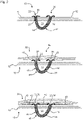
- Fig. 1
- and
- Fig. 2
- depict steps of an embodiment of a method according to the invention;
- Fig. 3
- depicts a top view of the a laminate with a split and pressed cord;
- Fig. 4
- depicts an embodiment of a load introduction feature preform;
- Fig. 5
- depicts a side view of a mounting arrangement; and
- Fig. 6
- depicts a cross-section of the mounting arrangement of
Fig. 5 . - As illustrated in
Fig. 1 andFig. 2 , alaminate structure 10 is initially provided. Thelaminate structure 10 comprises a plurality oflayers 12, eachlayer 12 being formed by a fiber ply or prepreg, for example. Thelaminate structure 10 has afirst laminate side 14 and an oppositesecond laminate side 16. - Subsequently, a
longitudinal fiber structure 18, preferably a cord, is provided. Thelongitudinal fiber structure 18 has afirst end portion 20 and an oppositesecond end portion 22. Thelongitudinal fiber structure 18 may include acenter portion 24 that has fibers that are aligned parallel to the longitudinal direction of the longitudinal fiber structure. Thecenter portion 24 may be surrounded by aperipheral portion 26 that has fibers that are aligned with an angle from ±30° to ±60° relative to the longitudinal direction. - The
first end portion 20 oflongitudinal fiber structure 18 is pulled from thefirst laminate side 14 through thelaminate structure 10 to thesecond laminate side 16 at afirst position 28. - The
first end portion 20 is then pulled, so as to form a loop-like configuration that defines anopening 30, and thefirst end portion 20 is brought to asecond position 32 that is spaced apart from thefirst position 28. - The
first end portion 20 is pulled from thesecond laminate side 14 through thelaminate structure 10 to thefirst laminate side 16 at thesecond position 28. As a result, thefirst end portion 20 and thesecond end portion 22 protrude from thelaminate structure 10 on thefirst laminate side 16. The remaininglongitudinal fiber structure 18 is designated as anintermediate portion 34 and defines theopening 30 together with a portion of thelaminate structure 10. - The
first end portion 20 and thesecond end portion 22 are split and the fibers are spread out to form a substantially circular or disk-like shape on thefirst laminate side 14, as illustrated more closely inFig. 3 . It is also possible that the first andsecond end portion layers 12, as indicated inFig. 4 . - In this state, the
first end portion 20 and thesecond end portion 22form fixing members 36 that allow a secure fixing of the lug, when in a cured state. Thefirst end portion 20 and thesecond end portion 22 may be pressed against thelaminate structure 10. - A
further laminate structure 38 that has a plurality offurther layers 40 is arranged on thefirst laminate side 14 so as to cover the fixingmembers 36. Alternatively, one or morelaminate patches 42 may be arranged between the first andsecond end portions - After these steps, the
opening 30 and thelongitudinal fiber structure 18 form a loadintroduction feature preform 44 that may be separate or integrated into a fibercomposite laminate preform 46. The loadintroduction feature preform 44 takes the configuration of a loop or lugpreform 48. If the loadintroduction feature preform 44 is separate, it may be laid onto the fibercomposite laminate preform 46 as illustrated inFig. 4 , and thelaminate structure 10 and thefurther laminate structure 38 form abase portion 50 of the loadintroduction feature preform 44. If theload introduction feature 44 is integrated into the fibercomposite laminate preform 46, then thelaminate structure 10 and thefurther laminate structure 38 are also part of thecomposite laminate preform 46. - In a further step, the load
introduction feature preform 44 and the fibercomposite laminate preform 46 may be infused with matrix material and cured in a manner known per se. The result is a fibercomposite laminate part 52 that has aload introduction feature 54, and they are integrally formed as a single unitary member. -
Fig. 5 and Fig. 6 depicts an embodiment of a mountingarrangement 56 for the fibercomposite laminate part 52. Aplate member 58 is arranged on each side of theload introduction feature 54, respectively. Eachplate member 58 has ahole 60 for a fastener. Theplate members 58 are fastened to each other using a plurality ofbolts 62 such that theplate members 58 are clamped to theload introduction feature 54. - In order to improve load introduction into a fiber composite laminate part (52), the invention proposes to integrate a mounting lug (54) by pulling a cord (18) through an initial laminate structure (10) such that an opening (30) is formed. The ends (20, 22) of the cord (18) are split and pressed onto the laminate structure (10) thereby forming fixing members (36) that are subsequently covered by another laminate structure (38). Laminate patches (42) may be arranged next to the fixing members (36) so as to improve smoothness of the surface. The mounting lug (54) may be clamped between two plates (58) for mounting to another structure.
-
- 10
- laminate structure
- 12
- layer
- 14
- first laminate side
- 16
- second laminate side
- 18
- longitudinal fiber structure
- 20
- first end portion
- 22
- second end portion
- 24
- center portion
- 26
- peripheral portion
- 28
- first position
- 30
- opening
- 32
- second position
- 34
- intermediate portion
- 36
- fixing members
- 38
- further laminate structure
- 40
- further layers
- 42
- laminate patch
- 44
- load introduction feature preform
- 46
- fiber composite laminate preform
- 48
- lug preform
- 50
- base portion
- 52
- fiber composite laminate part
- 54
- load introduction feature
- 56
- mounting arrangement
- 58
- plate member
- 60
- hole
- 62
- bolt
Claims (15)
- A method for manufacturing a load introduction feature preform (44) for a fiber composite laminate part (52), the method comprising:a) providing a laminate structure (10) that includes a plurality of layers (12); andb) pulling a longitudinal fiber structure (18) through the laminate structure (10) such that an opening (30) is formed, the opening (30) being defined by a portion of the longitudinal fiber structure (18) and a portion of the laminate structure (10).
- The method according to claim 1, wherein the laminate structure (10) defines a first laminate side (14) and an opposite second laminate side (16), and the longitudinal fiber structure (18) is pulled from the first laminate side (14) to the second laminate side (16) and from the second laminate side (16) to the first laminate side (14), so as to form the opening(30).
- The method according to claim 2, wherein in step b) the longitudinal fiber structure (18) is pulled through the laminate structure (10) from the first laminate side (14) to the second laminate side (16) at a first position (28) and pulled from the second laminate side (16) to the first laminate side (14) at a second position (32) that is spaced apart from the first position (28).
- The method according to any of the preceding claims, wherein the longitudinal fiber structure (18) comprises a first end portion (20), a second end portion (22), and an intermediate portion (34) that is arranged between the first and second end portions (20, 22), wherein in step b) the first end portion (20) is pulled through the laminate structure (10) until the first and second end portion (20, 22) protrude from one side of the laminate structure (10) and the intermediate portion (34) is arranged on an opposite side of the laminate structure (10).
- The method according to claim 4, wherein the first end portion (20) and/or second end portion (22) is/are circularly split and pressed onto the laminate structure (10), or wherein the first end portion (20) and/or second end portion (22) is/are bent to be parallel to the layers (12) of the laminate structure (10).
- The method according to any of the preceding claims, comprising a step:c) arranging a further laminate structure (38) having a plurality of layers (40) on a side opposite of the opening (30).
- The method according to claim 6, wherein steps b) and c) are executed in alternation, and in step b) another longitudinal fiber structure (18) is pulled through the laminate structure (10) and the further laminate structure(s) (38).
- The method according to any of the preceding claims, wherein in step b) at least one laminate patch (42) is arranged on the opposite side of the opening (30), the laminate patch (42) having a height that corresponds to a protruding portion of the longitudinal fiber structure (18).
- The method according to any of the preceding claims, wherein step b) is repeated with another longitudinal fiber structure at the same position or adjacent positions.
- The method according to any of the preceding claims, wherein the longitudinal fiber structure (18) is configured as a cord.
- The method according to claim 10, wherein the cord comprises a center portion (24) and a peripheral portion (26) that surrounds the center portion (24), wherein a fiber orientation of the center portion (24) is along the longitudinal direction of the longitudinal fiber structure (18), and a fiber orientation of the peripheral portion (26) differs from the fiber orientation of the center portion.
- A method for manufacturing a fiber composite laminate part (52) having an integral load introduction feature (54), the method comprising:a) performing a method according to any of the preceding claims, so as to obtain a separate load introduction feature preform (44) and adding it to a laminate composite preform (46), or so as to form the load introduction feature preform (44) on the laminate composite preform (46);b) curing the laminate composite preform (46) and the load introduction feature preform (44) into a fiber composite laminate part (52) with integral load introduction feature (54) formed by the opening (30), the longitudinal fiber structure (18) and the laminate structure (10).
- The method according to claim 12, further comprising a step:c) arranging a pair of plate members (58) each having a hole (60) such that the opening (30) overlaps the holes (60) in a way that allows insertion of an elongated member, and fixing the plate members (58) to the load introduction feature (54) by clamping.
- A load introduction feature preform (44) for a fiber composite laminate part (52), wherein the load introduction feature preform (44) is obtainable through a method according to any of the claims 1 to 11.
- A fiber composite laminate part (52), wherein the fiber composite laminate part (52) is obtainable through a method according to claim 12 or 13.
Priority Applications (1)
| Application Number | Priority Date | Filing Date | Title |
|---|---|---|---|
| EP21182907.2A EP4112283B1 (en) | 2021-06-30 | 2021-06-30 | Method for manufacturing a load introduction feature for a fiber composite laminate part |
Applications Claiming Priority (1)
| Application Number | Priority Date | Filing Date | Title |
|---|---|---|---|
| EP21182907.2A EP4112283B1 (en) | 2021-06-30 | 2021-06-30 | Method for manufacturing a load introduction feature for a fiber composite laminate part |
Publications (2)
| Publication Number | Publication Date |
|---|---|
| EP4112283A1 true EP4112283A1 (en) | 2023-01-04 |
| EP4112283B1 EP4112283B1 (en) | 2026-04-22 |
Family
ID=76730441
Family Applications (1)
| Application Number | Title | Priority Date | Filing Date |
|---|---|---|---|
| EP21182907.2A Active EP4112283B1 (en) | 2021-06-30 | 2021-06-30 | Method for manufacturing a load introduction feature for a fiber composite laminate part |
Country Status (1)
| Country | Link |
|---|---|
| EP (1) | EP4112283B1 (en) |
Citations (2)
| Publication number | Priority date | Publication date | Assignee | Title |
|---|---|---|---|---|
| WO1999019137A1 (en) * | 1997-10-15 | 1999-04-22 | N.V. Syncoglas S.A. | Three-dimensional strengthening material |
| WO2004041528A2 (en) * | 2002-11-01 | 2004-05-21 | Bell Helicopter Textron Inc. | Method and apparatus for z-direction reinforcement of composite laminates |
-
2021
- 2021-06-30 EP EP21182907.2A patent/EP4112283B1/en active Active
Patent Citations (2)
| Publication number | Priority date | Publication date | Assignee | Title |
|---|---|---|---|---|
| WO1999019137A1 (en) * | 1997-10-15 | 1999-04-22 | N.V. Syncoglas S.A. | Three-dimensional strengthening material |
| WO2004041528A2 (en) * | 2002-11-01 | 2004-05-21 | Bell Helicopter Textron Inc. | Method and apparatus for z-direction reinforcement of composite laminates |
Also Published As
| Publication number | Publication date |
|---|---|
| EP4112283B1 (en) | 2026-04-22 |
Similar Documents
| Publication | Publication Date | Title |
|---|---|---|
| CN101249885B (en) | Rib support for wing panels | |
| AU2011253392B2 (en) | Composite beam chord between reinforcement plates and related method of manufacturing | |
| US6245275B1 (en) | Method for fabricating composite structures | |
| KR101790439B1 (en) | Joint for composite wings | |
| RU2715525C2 (en) | Aircraft structure to ensure high resistance to pulling off composite stringer | |
| EP1288124A1 (en) | A method of manufacturing a composite material wing and a composite material wing | |
| EP2678146B1 (en) | Method for producing a connector and connector for an aircraft or a spacecraft | |
| US8795578B2 (en) | Apparatus and method for forming fibre reinforced composite structures | |
| US20100320320A1 (en) | Aeropspace structure including composite beam chord clamped between reinforcement plates | |
| US6478922B1 (en) | Method of manufacturing a composite structure using a conformable locating aperture system | |
| JP2013504468A (en) | Radome and apparatus for attaching the radome to an aircraft | |
| US9090025B2 (en) | Fitting including a composite material bracket and a stiffener | |
| US7780808B2 (en) | Method of reinforcing a laminated member such as a skin for an aircraft | |
| CN102741122A (en) | Fastening arrangement for fastening a component on a fuselage | |
| EP2234793B1 (en) | Piece made of composite material with areas of different thickness | |
| EP4112283B1 (en) | Method for manufacturing a load introduction feature for a fiber composite laminate part | |
| US8708279B2 (en) | Composite structural member with progressive rigidity | |
| WO2022147383A1 (en) | Iso-truss structure and coupling mechanism for iso-truss structure | |
| US9682519B2 (en) | Integral composite bushing system and method | |
| JP2011240925A5 (en) | ||
| GB2582159A (en) | Load-transferring components | |
| US7481398B2 (en) | Intercostal for aircraft | |
| US20250367888A1 (en) | Composite radius fillers, assemblies including composite radius fillers, and systems and methods of forming the same | |
| JP2021062588A (en) | Composite material with reinforcing fiber bundle, and bolt-fastened structure | |
| US12459221B2 (en) | Method for producing a torsion box for a structure of an airplane and a torsion box for a structure of an airplane |
Legal Events
| Date | Code | Title | Description |
|---|---|---|---|
| PUAI | Public reference made under article 153(3) epc to a published international application that has entered the european phase |
Free format text: ORIGINAL CODE: 0009012 |
|
| STAA | Information on the status of an ep patent application or granted ep patent |
Free format text: STATUS: THE APPLICATION HAS BEEN PUBLISHED |
|
| AK | Designated contracting states |
Kind code of ref document: A1 Designated state(s): AL AT BE BG CH CY CZ DE DK EE ES FI FR GB GR HR HU IE IS IT LI LT LU LV MC MK MT NL NO PL PT RO RS SE SI SK SM TR |
|
| STAA | Information on the status of an ep patent application or granted ep patent |
Free format text: STATUS: REQUEST FOR EXAMINATION WAS MADE |
|
| 17P | Request for examination filed |
Effective date: 20230704 |
|
| RBV | Designated contracting states (corrected) |
Designated state(s): AL AT BE BG CH CY CZ DE DK EE ES FI FR GB GR HR HU IE IS IT LI LT LU LV MC MK MT NL NO PL PT RO RS SE SI SK SM TR |
|
| GRAP | Despatch of communication of intention to grant a patent |
Free format text: ORIGINAL CODE: EPIDOSNIGR1 |
|
| STAA | Information on the status of an ep patent application or granted ep patent |
Free format text: STATUS: GRANT OF PATENT IS INTENDED |
|
| RIC1 | Information provided on ipc code assigned before grant |
Ipc: B29C 70/82 20060101AFI20251127BHEP Ipc: B29C 70/24 20060101ALI20251127BHEP Ipc: B29C 70/68 20060101ALI20251127BHEP Ipc: B29C 65/62 20060101ALI20251127BHEP Ipc: B29C 70/72 20060101ALI20251127BHEP Ipc: D04B 21/16 20060101ALN20251127BHEP Ipc: B64C 1/00 20060101ALN20251127BHEP |
|
| INTG | Intention to grant announced |
Effective date: 20251209 |
|
| RIC1 | Information provided on ipc code assigned before grant |
Ipc: B29C 70/82 20060101AFI20251202BHEP Ipc: B29C 70/24 20060101ALI20251202BHEP Ipc: B29C 70/68 20060101ALI20251202BHEP Ipc: B29C 65/62 20060101ALI20251202BHEP Ipc: B29C 70/72 20060101ALI20251202BHEP Ipc: D04B 21/16 20060101ALN20251202BHEP Ipc: B64C 1/00 20060101ALN20251202BHEP |
|
| GRAS | Grant fee paid |
Free format text: ORIGINAL CODE: EPIDOSNIGR3 |
|
| GRAA | (expected) grant |
Free format text: ORIGINAL CODE: 0009210 |
|
| STAA | Information on the status of an ep patent application or granted ep patent |
Free format text: STATUS: THE PATENT HAS BEEN GRANTED |
|
| AK | Designated contracting states |
Kind code of ref document: B1 Designated state(s): AL AT BE BG CH CY CZ DE DK EE ES FI FR GB GR HR HU IE IS IT LI LT LU LV MC MK MT NL NO PL PT RO RS SE SI SK SM TR |
|
| REG | Reference to a national code |
Ref country code: CH Ref legal event code: F10 Free format text: ST27 STATUS EVENT CODE: U-0-0-F10-F00 (AS PROVIDED BY THE NATIONAL OFFICE) Effective date: 20260422 Ref country code: GB Ref legal event code: FG4D |