EP4112278A1 - Pouch-type battery case sealing apparatus and pouch-type secondary battery sealing method using same - Google Patents
Pouch-type battery case sealing apparatus and pouch-type secondary battery sealing method using same Download PDFInfo
- Publication number
- EP4112278A1 EP4112278A1 EP21915693.2A EP21915693A EP4112278A1 EP 4112278 A1 EP4112278 A1 EP 4112278A1 EP 21915693 A EP21915693 A EP 21915693A EP 4112278 A1 EP4112278 A1 EP 4112278A1
- Authority
- EP
- European Patent Office
- Prior art keywords
- pouch
- shaped battery
- battery case
- sealing block
- sealing
- Prior art date
- Legal status (The legal status is an assumption and is not a legal conclusion. Google has not performed a legal analysis and makes no representation as to the accuracy of the status listed.)
- Granted
Links
Images


Classifications
-
- B—PERFORMING OPERATIONS; TRANSPORTING
- B29—WORKING OF PLASTICS; WORKING OF SUBSTANCES IN A PLASTIC STATE IN GENERAL
- B29C—SHAPING OR JOINING OF PLASTICS; SHAPING OF MATERIAL IN A PLASTIC STATE, NOT OTHERWISE PROVIDED FOR; AFTER-TREATMENT OF THE SHAPED PRODUCTS, e.g. REPAIRING
- B29C66/00—General aspects of processes or apparatus for joining preformed parts
- B29C66/80—General aspects of machine operations or constructions and parts thereof
- B29C66/83—General aspects of machine operations or constructions and parts thereof characterised by the movement of the joining or pressing tools
-
- H—ELECTRICITY
- H01—ELECTRIC ELEMENTS
- H01M—PROCESSES OR MEANS, e.g. BATTERIES, FOR THE DIRECT CONVERSION OF CHEMICAL ENERGY INTO ELECTRICAL ENERGY
- H01M10/00—Secondary cells; Manufacture thereof
- H01M10/04—Construction or manufacture in general
- H01M10/0404—Machines for assembling batteries
-
- B—PERFORMING OPERATIONS; TRANSPORTING
- B29—WORKING OF PLASTICS; WORKING OF SUBSTANCES IN A PLASTIC STATE IN GENERAL
- B29C—SHAPING OR JOINING OF PLASTICS; SHAPING OF MATERIAL IN A PLASTIC STATE, NOT OTHERWISE PROVIDED FOR; AFTER-TREATMENT OF THE SHAPED PRODUCTS, e.g. REPAIRING
- B29C65/00—Joining or sealing of preformed parts, e.g. welding of plastics materials; Apparatus therefor
- B29C65/02—Joining or sealing of preformed parts, e.g. welding of plastics materials; Apparatus therefor by heating, with or without pressure
-
- B—PERFORMING OPERATIONS; TRANSPORTING
- B29—WORKING OF PLASTICS; WORKING OF SUBSTANCES IN A PLASTIC STATE IN GENERAL
- B29C—SHAPING OR JOINING OF PLASTICS; SHAPING OF MATERIAL IN A PLASTIC STATE, NOT OTHERWISE PROVIDED FOR; AFTER-TREATMENT OF THE SHAPED PRODUCTS, e.g. REPAIRING
- B29C66/00—General aspects of processes or apparatus for joining preformed parts
- B29C66/01—General aspects dealing with the joint area or with the area to be joined
- B29C66/05—Particular design of joint configurations
- B29C66/10—Particular design of joint configurations particular design of the joint cross-sections
- B29C66/11—Joint cross-sections comprising a single joint-segment, i.e. one of the parts to be joined comprising a single joint-segment in the joint cross-section
- B29C66/112—Single lapped joints
-
- B—PERFORMING OPERATIONS; TRANSPORTING
- B29—WORKING OF PLASTICS; WORKING OF SUBSTANCES IN A PLASTIC STATE IN GENERAL
- B29C—SHAPING OR JOINING OF PLASTICS; SHAPING OF MATERIAL IN A PLASTIC STATE, NOT OTHERWISE PROVIDED FOR; AFTER-TREATMENT OF THE SHAPED PRODUCTS, e.g. REPAIRING
- B29C66/00—General aspects of processes or apparatus for joining preformed parts
- B29C66/01—General aspects dealing with the joint area or with the area to be joined
- B29C66/05—Particular design of joint configurations
- B29C66/10—Particular design of joint configurations particular design of the joint cross-sections
- B29C66/13—Single flanged joints; Fin-type joints; Single hem joints; Edge joints; Interpenetrating fingered joints; Other specific particular designs of joint cross-sections not provided for in groups B29C66/11 - B29C66/12
- B29C66/131—Single flanged joints, i.e. one of the parts to be joined being rigid and flanged in the joint area
-
- B—PERFORMING OPERATIONS; TRANSPORTING
- B29—WORKING OF PLASTICS; WORKING OF SUBSTANCES IN A PLASTIC STATE IN GENERAL
- B29C—SHAPING OR JOINING OF PLASTICS; SHAPING OF MATERIAL IN A PLASTIC STATE, NOT OTHERWISE PROVIDED FOR; AFTER-TREATMENT OF THE SHAPED PRODUCTS, e.g. REPAIRING
- B29C66/00—General aspects of processes or apparatus for joining preformed parts
- B29C66/01—General aspects dealing with the joint area or with the area to be joined
- B29C66/05—Particular design of joint configurations
- B29C66/20—Particular design of joint configurations particular design of the joint lines, e.g. of the weld lines
- B29C66/24—Particular design of joint configurations particular design of the joint lines, e.g. of the weld lines said joint lines being closed or non-straight
- B29C66/242—Particular design of joint configurations particular design of the joint lines, e.g. of the weld lines said joint lines being closed or non-straight said joint lines being closed, i.e. forming closed contours
- B29C66/2424—Particular design of joint configurations particular design of the joint lines, e.g. of the weld lines said joint lines being closed or non-straight said joint lines being closed, i.e. forming closed contours being a closed polygonal chain
- B29C66/24243—Particular design of joint configurations particular design of the joint lines, e.g. of the weld lines said joint lines being closed or non-straight said joint lines being closed, i.e. forming closed contours being a closed polygonal chain forming a quadrilateral
- B29C66/24244—Particular design of joint configurations particular design of the joint lines, e.g. of the weld lines said joint lines being closed or non-straight said joint lines being closed, i.e. forming closed contours being a closed polygonal chain forming a quadrilateral forming a rectangle
-
- B—PERFORMING OPERATIONS; TRANSPORTING
- B29—WORKING OF PLASTICS; WORKING OF SUBSTANCES IN A PLASTIC STATE IN GENERAL
- B29C—SHAPING OR JOINING OF PLASTICS; SHAPING OF MATERIAL IN A PLASTIC STATE, NOT OTHERWISE PROVIDED FOR; AFTER-TREATMENT OF THE SHAPED PRODUCTS, e.g. REPAIRING
- B29C66/00—General aspects of processes or apparatus for joining preformed parts
- B29C66/40—General aspects of joining substantially flat articles, e.g. plates, sheets or web-like materials; Making flat seams in tubular or hollow articles; Joining single elements to substantially flat surfaces
- B29C66/41—Joining substantially flat articles ; Making flat seams in tubular or hollow articles
- B29C66/43—Joining a relatively small portion of the surface of said articles
- B29C66/433—Casing-in, i.e. enclosing an element between two sheets by an outlined seam
-
- B—PERFORMING OPERATIONS; TRANSPORTING
- B29—WORKING OF PLASTICS; WORKING OF SUBSTANCES IN A PLASTIC STATE IN GENERAL
- B29C—SHAPING OR JOINING OF PLASTICS; SHAPING OF MATERIAL IN A PLASTIC STATE, NOT OTHERWISE PROVIDED FOR; AFTER-TREATMENT OF THE SHAPED PRODUCTS, e.g. REPAIRING
- B29C66/00—General aspects of processes or apparatus for joining preformed parts
- B29C66/50—General aspects of joining tubular articles; General aspects of joining long products, i.e. bars or profiled elements; General aspects of joining single elements to tubular articles, hollow articles or bars; General aspects of joining several hollow-preforms to form hollow or tubular articles
- B29C66/51—Joining tubular articles, profiled elements or bars; Joining single elements to tubular articles, hollow articles or bars; Joining several hollow-preforms to form hollow or tubular articles
- B29C66/53—Joining single elements to tubular articles, hollow articles or bars
- B29C66/534—Joining single elements to open ends of tubular or hollow articles or to the ends of bars
- B29C66/5346—Joining single elements to open ends of tubular or hollow articles or to the ends of bars said single elements being substantially flat
- B29C66/53461—Joining single elements to open ends of tubular or hollow articles or to the ends of bars said single elements being substantially flat joining substantially flat covers and/or substantially flat bottoms to open ends of container bodies
-
- B—PERFORMING OPERATIONS; TRANSPORTING
- B29—WORKING OF PLASTICS; WORKING OF SUBSTANCES IN A PLASTIC STATE IN GENERAL
- B29C—SHAPING OR JOINING OF PLASTICS; SHAPING OF MATERIAL IN A PLASTIC STATE, NOT OTHERWISE PROVIDED FOR; AFTER-TREATMENT OF THE SHAPED PRODUCTS, e.g. REPAIRING
- B29C66/00—General aspects of processes or apparatus for joining preformed parts
- B29C66/50—General aspects of joining tubular articles; General aspects of joining long products, i.e. bars or profiled elements; General aspects of joining single elements to tubular articles, hollow articles or bars; General aspects of joining several hollow-preforms to form hollow or tubular articles
- B29C66/51—Joining tubular articles, profiled elements or bars; Joining single elements to tubular articles, hollow articles or bars; Joining several hollow-preforms to form hollow or tubular articles
- B29C66/54—Joining several hollow-preforms, e.g. half-shells, to form hollow articles, e.g. for making balls, containers; Joining several hollow-preforms, e.g. half-cylinders, to form tubular articles
- B29C66/549—Joining several hollow-preforms, e.g. half-shells, to form hollow articles, e.g. for making balls, containers; Joining several hollow-preforms, e.g. half-cylinders, to form tubular articles said hollow-preforms being interconnected during their moulding process, e.g. by a hinge
-
- B—PERFORMING OPERATIONS; TRANSPORTING
- B29—WORKING OF PLASTICS; WORKING OF SUBSTANCES IN A PLASTIC STATE IN GENERAL
- B29C—SHAPING OR JOINING OF PLASTICS; SHAPING OF MATERIAL IN A PLASTIC STATE, NOT OTHERWISE PROVIDED FOR; AFTER-TREATMENT OF THE SHAPED PRODUCTS, e.g. REPAIRING
- B29C66/00—General aspects of processes or apparatus for joining preformed parts
- B29C66/70—General aspects of processes or apparatus for joining preformed parts characterised by the composition, physical properties or the structure of the material of the parts to be joined; Joining with non-plastics material
- B29C66/72—General aspects of processes or apparatus for joining preformed parts characterised by the composition, physical properties or the structure of the material of the parts to be joined; Joining with non-plastics material characterised by the structure of the material of the parts to be joined
- B29C66/723—General aspects of processes or apparatus for joining preformed parts characterised by the composition, physical properties or the structure of the material of the parts to be joined; Joining with non-plastics material characterised by the structure of the material of the parts to be joined being multi-layered
- B29C66/7232—General aspects of processes or apparatus for joining preformed parts characterised by the composition, physical properties or the structure of the material of the parts to be joined; Joining with non-plastics material characterised by the structure of the material of the parts to be joined being multi-layered comprising a non-plastics layer
- B29C66/72321—General aspects of processes or apparatus for joining preformed parts characterised by the composition, physical properties or the structure of the material of the parts to be joined; Joining with non-plastics material characterised by the structure of the material of the parts to be joined being multi-layered comprising a non-plastics layer consisting of metals or their alloys
-
- B—PERFORMING OPERATIONS; TRANSPORTING
- B29—WORKING OF PLASTICS; WORKING OF SUBSTANCES IN A PLASTIC STATE IN GENERAL
- B29C—SHAPING OR JOINING OF PLASTICS; SHAPING OF MATERIAL IN A PLASTIC STATE, NOT OTHERWISE PROVIDED FOR; AFTER-TREATMENT OF THE SHAPED PRODUCTS, e.g. REPAIRING
- B29C66/00—General aspects of processes or apparatus for joining preformed parts
- B29C66/70—General aspects of processes or apparatus for joining preformed parts characterised by the composition, physical properties or the structure of the material of the parts to be joined; Joining with non-plastics material
- B29C66/73—General aspects of processes or apparatus for joining preformed parts characterised by the composition, physical properties or the structure of the material of the parts to be joined; Joining with non-plastics material characterised by the intensive physical properties of the material of the parts to be joined, by the optical properties of the material of the parts to be joined, by the extensive physical properties of the parts to be joined, by the state of the material of the parts to be joined or by the material of the parts to be joined being a thermoplastic or a thermoset
- B29C66/739—General aspects of processes or apparatus for joining preformed parts characterised by the composition, physical properties or the structure of the material of the parts to be joined; Joining with non-plastics material characterised by the intensive physical properties of the material of the parts to be joined, by the optical properties of the material of the parts to be joined, by the extensive physical properties of the parts to be joined, by the state of the material of the parts to be joined or by the material of the parts to be joined being a thermoplastic or a thermoset characterised by the material of the parts to be joined being a thermoplastic or a thermoset
- B29C66/7392—General aspects of processes or apparatus for joining preformed parts characterised by the composition, physical properties or the structure of the material of the parts to be joined; Joining with non-plastics material characterised by the intensive physical properties of the material of the parts to be joined, by the optical properties of the material of the parts to be joined, by the extensive physical properties of the parts to be joined, by the state of the material of the parts to be joined or by the material of the parts to be joined being a thermoplastic or a thermoset characterised by the material of the parts to be joined being a thermoplastic or a thermoset characterised by the material of at least one of the parts being a thermoplastic
- B29C66/73921—General aspects of processes or apparatus for joining preformed parts characterised by the composition, physical properties or the structure of the material of the parts to be joined; Joining with non-plastics material characterised by the intensive physical properties of the material of the parts to be joined, by the optical properties of the material of the parts to be joined, by the extensive physical properties of the parts to be joined, by the state of the material of the parts to be joined or by the material of the parts to be joined being a thermoplastic or a thermoset characterised by the material of the parts to be joined being a thermoplastic or a thermoset characterised by the material of at least one of the parts being a thermoplastic characterised by the materials of both parts being thermoplastics
-
- B—PERFORMING OPERATIONS; TRANSPORTING
- B29—WORKING OF PLASTICS; WORKING OF SUBSTANCES IN A PLASTIC STATE IN GENERAL
- B29C—SHAPING OR JOINING OF PLASTICS; SHAPING OF MATERIAL IN A PLASTIC STATE, NOT OTHERWISE PROVIDED FOR; AFTER-TREATMENT OF THE SHAPED PRODUCTS, e.g. REPAIRING
- B29C66/00—General aspects of processes or apparatus for joining preformed parts
- B29C66/80—General aspects of machine operations or constructions and parts thereof
- B29C66/81—General aspects of the pressing elements, i.e. the elements applying pressure on the parts to be joined in the area to be joined, e.g. the welding jaws or clamps
- B29C66/816—General aspects of the pressing elements, i.e. the elements applying pressure on the parts to be joined in the area to be joined, e.g. the welding jaws or clamps characterised by the mounting of the pressing elements, e.g. of the welding jaws or clamps
- B29C66/8163—Self-aligning to the joining plane, e.g. mounted on a ball and socket
-
- B—PERFORMING OPERATIONS; TRANSPORTING
- B29—WORKING OF PLASTICS; WORKING OF SUBSTANCES IN A PLASTIC STATE IN GENERAL
- B29C—SHAPING OR JOINING OF PLASTICS; SHAPING OF MATERIAL IN A PLASTIC STATE, NOT OTHERWISE PROVIDED FOR; AFTER-TREATMENT OF THE SHAPED PRODUCTS, e.g. REPAIRING
- B29C66/00—General aspects of processes or apparatus for joining preformed parts
- B29C66/80—General aspects of machine operations or constructions and parts thereof
- B29C66/83—General aspects of machine operations or constructions and parts thereof characterised by the movement of the joining or pressing tools
- B29C66/832—Reciprocating joining or pressing tools
-
- B—PERFORMING OPERATIONS; TRANSPORTING
- B29—WORKING OF PLASTICS; WORKING OF SUBSTANCES IN A PLASTIC STATE IN GENERAL
- B29C—SHAPING OR JOINING OF PLASTICS; SHAPING OF MATERIAL IN A PLASTIC STATE, NOT OTHERWISE PROVIDED FOR; AFTER-TREATMENT OF THE SHAPED PRODUCTS, e.g. REPAIRING
- B29C66/00—General aspects of processes or apparatus for joining preformed parts
- B29C66/80—General aspects of machine operations or constructions and parts thereof
- B29C66/83—General aspects of machine operations or constructions and parts thereof characterised by the movement of the joining or pressing tools
- B29C66/832—Reciprocating joining or pressing tools
- B29C66/8322—Joining or pressing tools reciprocating along one axis
-
- B—PERFORMING OPERATIONS; TRANSPORTING
- B29—WORKING OF PLASTICS; WORKING OF SUBSTANCES IN A PLASTIC STATE IN GENERAL
- B29C—SHAPING OR JOINING OF PLASTICS; SHAPING OF MATERIAL IN A PLASTIC STATE, NOT OTHERWISE PROVIDED FOR; AFTER-TREATMENT OF THE SHAPED PRODUCTS, e.g. REPAIRING
- B29C66/00—General aspects of processes or apparatus for joining preformed parts
- B29C66/80—General aspects of machine operations or constructions and parts thereof
- B29C66/83—General aspects of machine operations or constructions and parts thereof characterised by the movement of the joining or pressing tools
- B29C66/832—Reciprocating joining or pressing tools
- B29C66/8324—Joining or pressing tools pivoting around one axis
-
- B—PERFORMING OPERATIONS; TRANSPORTING
- B29—WORKING OF PLASTICS; WORKING OF SUBSTANCES IN A PLASTIC STATE IN GENERAL
- B29C—SHAPING OR JOINING OF PLASTICS; SHAPING OF MATERIAL IN A PLASTIC STATE, NOT OTHERWISE PROVIDED FOR; AFTER-TREATMENT OF THE SHAPED PRODUCTS, e.g. REPAIRING
- B29C66/00—General aspects of processes or apparatus for joining preformed parts
- B29C66/90—Measuring or controlling the joining process
- B29C66/92—Measuring or controlling the joining process by measuring or controlling the pressure, the force, the mechanical power or the displacement of the joining tools
- B29C66/924—Measuring or controlling the joining process by measuring or controlling the pressure, the force, the mechanical power or the displacement of the joining tools by controlling or regulating the pressure, the force, the mechanical power or the displacement of the joining tools
- B29C66/9261—Measuring or controlling the joining process by measuring or controlling the pressure, the force, the mechanical power or the displacement of the joining tools by controlling or regulating the pressure, the force, the mechanical power or the displacement of the joining tools by controlling or regulating the displacement of the joining tools
- B29C66/92651—Measuring or controlling the joining process by measuring or controlling the pressure, the force, the mechanical power or the displacement of the joining tools by controlling or regulating the pressure, the force, the mechanical power or the displacement of the joining tools by controlling or regulating the displacement of the joining tools by using stops
- B29C66/92655—Measuring or controlling the joining process by measuring or controlling the pressure, the force, the mechanical power or the displacement of the joining tools by controlling or regulating the pressure, the force, the mechanical power or the displacement of the joining tools by controlling or regulating the displacement of the joining tools by using stops by using several stops
-
- H—ELECTRICITY
- H01—ELECTRIC ELEMENTS
- H01M—PROCESSES OR MEANS, e.g. BATTERIES, FOR THE DIRECT CONVERSION OF CHEMICAL ENERGY INTO ELECTRICAL ENERGY
- H01M10/00—Secondary cells; Manufacture thereof
- H01M10/04—Construction or manufacture in general
- H01M10/0436—Small-sized flat cells or batteries for portable equipment
-
- H—ELECTRICITY
- H01—ELECTRIC ELEMENTS
- H01M—PROCESSES OR MEANS, e.g. BATTERIES, FOR THE DIRECT CONVERSION OF CHEMICAL ENERGY INTO ELECTRICAL ENERGY
- H01M50/00—Constructional details or processes of manufacture of the non-active parts of electrochemical cells other than fuel cells, e.g. hybrid cells
- H01M50/10—Primary casings; Jackets or wrappings
- H01M50/102—Primary casings; Jackets or wrappings characterised by their shape or physical structure
- H01M50/105—Pouches or flexible bags
-
- H—ELECTRICITY
- H01—ELECTRIC ELEMENTS
- H01M—PROCESSES OR MEANS, e.g. BATTERIES, FOR THE DIRECT CONVERSION OF CHEMICAL ENERGY INTO ELECTRICAL ENERGY
- H01M50/00—Constructional details or processes of manufacture of the non-active parts of electrochemical cells other than fuel cells, e.g. hybrid cells
- H01M50/10—Primary casings; Jackets or wrappings
- H01M50/183—Sealing members
- H01M50/186—Sealing members characterised by the disposition of the sealing members
-
- B—PERFORMING OPERATIONS; TRANSPORTING
- B29—WORKING OF PLASTICS; WORKING OF SUBSTANCES IN A PLASTIC STATE IN GENERAL
- B29L—INDEXING SCHEME ASSOCIATED WITH SUBCLASS B29C, RELATING TO PARTICULAR ARTICLES
- B29L2031/00—Other particular articles
- B29L2031/712—Containers; Packaging elements or accessories, Packages
- B29L2031/7146—Battery-cases
-
- Y—GENERAL TAGGING OF NEW TECHNOLOGICAL DEVELOPMENTS; GENERAL TAGGING OF CROSS-SECTIONAL TECHNOLOGIES SPANNING OVER SEVERAL SECTIONS OF THE IPC; TECHNICAL SUBJECTS COVERED BY FORMER USPC CROSS-REFERENCE ART COLLECTIONS [XRACs] AND DIGESTS
- Y02—TECHNOLOGIES OR APPLICATIONS FOR MITIGATION OR ADAPTATION AGAINST CLIMATE CHANGE
- Y02E—REDUCTION OF GREENHOUSE GAS [GHG] EMISSIONS, RELATED TO ENERGY GENERATION, TRANSMISSION OR DISTRIBUTION
- Y02E60/00—Enabling technologies; Technologies with a potential or indirect contribution to GHG emissions mitigation
- Y02E60/10—Energy storage using batteries
Definitions
- Patent Document 2 relates to a sealing apparatus used to seal a secondary battery packaging material, the sealing apparatus including a first sealing tool, a second sealing tool configured to perform sealing while facing the first sealing tool, a first pulling unit attached to an end of the first sealing tool, and a second pulling unit attached to an end of the second sealing tool so as to correspond to the first pulling unit, wherein, in a sealing process, the first pulling unit pulls the end of the first sealing tool in a direction toward the second sealing tool, and the second pulling unit pulls the end of the second sealing tool in a direction toward the first sealing tool.
- the sealing apparatus according to the present invention is capable of securing a uniformly sealed surface within a short time while reducing a sealing defect rate.
Landscapes
- Engineering & Computer Science (AREA)
- Mechanical Engineering (AREA)
- Chemical & Material Sciences (AREA)
- Chemical Kinetics & Catalysis (AREA)
- Electrochemistry (AREA)
- General Chemical & Material Sciences (AREA)
- Manufacturing & Machinery (AREA)
- Sealing Battery Cases Or Jackets (AREA)
Abstract
Description
- This application claims the benefit of priority to
Korean Patent Application No. 2020-0184336 filed on December 28, 2020 - The present invention relates to a pouch-shaped battery case sealing apparatus and a pouch-shaped secondary battery sealing method using the same. More particularly, the present invention relates to a pouch-shaped battery case sealing apparatus capable of adjusting a direction in which an upper sealing block configured to press a laminate sheet applies pressure to the laminate sheet during a process of applying heat and pressure to an outer periphery of a battery case made of the laminate sheet to seal the outer periphery of the battery case when a pouch-shaped battery is manufactured and a pouch-shaped secondary battery sealing method using the same.
- Demand for a secondary battery as an energy source for mobile devices, electric vehicles, etc. has abruptly increased. In particular, demand for a lithium secondary battery, which has high energy density and high discharge voltage, is high.
- Based on the shape and material thereof, the lithium secondary battery may be classified as a cylindrical secondary battery made of a metal material, a prismatic secondary battery made of a metal material, or a pouch-shaped battery made of a laminate sheet. The pouch-shaped battery has advantages in that the pouch-shaped secondary battery is stacked with high degree of integration, thereby having high energy density per unit weight, is manufactured at low cost, and is easily deformable. Consequently, the pouch-shaped battery is used in various devices.
- In general, a laminate sheet including an outer coating layer, a metal blocking layer, and an inner adhesive layer is shaped so as to be used as a battery case of the pouch-shaped battery. An electrode assembly is received in a receiving portion formed in the laminate sheet together with an electrolytic solution, and the receiving portion is sealed, whereby the pouch-shaped battery is manufactured.
- As shown in
FIG. 1 , a pouch-shaped battery 50 is configured such that anelectrode assembly 20 is mounted in a receiving portion 13 of abattery case 10 constituted by a pouch-shapedlower part 11 and a pouch-shapedupper part 12. In theelectrode assembly 20, positive andnegative electrode tabs battery case 10 in a state of being welded respectively to two electrode leads 31 and 32. An outer periphery of thebattery case 10 is sealed in the state in which a pair ofinsulative films 41 and a pair ofinsulative films 42 are disposed respectively at an upper part and a lower part of theelectrode lead 31 and an upper part and a lower part of theelectrode lead 32. - The outer periphery of the
battery case 10 is sealed as the result of inner adhesive layers of laminate sheets being thermally melted and pressed by a rectangular parallelepiped sealing tool that is long in a longitudinal direction thereof. -
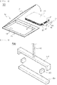
FIG. 2 is an exploded perspective view of a pouch-shapedbattery sealing apparatus 500 according to Patent Document 1. An outer periphery of a pouch-shaped battery is disposed between aholder 100 and asealing block 200. Theholder 100, which is movable upwards and downwards by a lifting means 110, is moved downwards, and the outer periphery of the pouch-shaped battery is heated and fused, whereby the outer periphery of the pouch-shaped battery is sealed. Theholder 100 and the lifting means 110 are fixed or are tiltable only in one direction. - Conventionally, the
holder 100 and the lifting means 110 are fixed. In recent years, demand for secondary batteries has rapidly increased, and therefore various attempts to reduce process time for each step have been made. Conventionally, theholder 100 fixed to the lifting means 100 sufficiently presses an outer periphery of a laminate sheet to seal the outer periphery of the laminate sheet. An attempt to change the structure of the holder so as to be tiltable in a direction toward thesealing block 200 in order to rapidly and uniformly performing pressing has been made. Since tilting is performed only in one direction, however, a pouch-shaped secondary battery defect rate is not reduced, and yield is also lowered. - Patent Document 1 relates to a battery cell having a welded surplus portion, the battery cell including an electrode assembly having a structure including a positive electrode, a negative electrode, a separator interposed between the positive electrode and the negative electrode; and a battery case having a structure including a sealed surplus portion at which an outer periphery of the battery case is sealed in the state in which the electrode assembly is received in the battery case, wherein the battery case is made of a laminate sheet having a structure in which a first resin layer, a metal layer, and a second resin layer are sequentially stacked from the side facing the electrode assembly, the sealed surplus portion is configured to have a structure in which a first sheet portion and a second sheet portion of the laminate sheet that face each other are joined to each other, at least a part of the sealed surplus portion includes a resin layer fusion portion formed by the first resin layer of the first sheet portion and the first resin layer of the second sheet portion and a metal layer weld portion formed by an end of the metal layer of the first sheet portion and an end of the metal layer of the second sheet portion.
- Patent Document 1 discloses that first and second sealing tools are disposed above and under the sheet portion and that the sealing tools are rotated so as to be inclined by a predetermined angle; however, the sealing tools are configured to be tilted only in one direction, as mentioned above. Furthermore, Patent Document 1 discloses a means configured to further press a part of the portion to be sealed, not the entire portion to be sealed, which cannot become a solution for uniformly sealing the entire portion to be sealed, which is achieved by the present invention.
- Patent Document 2 relates to a sealing apparatus used to seal a secondary battery packaging material, the sealing apparatus including a first sealing tool, a second sealing tool configured to perform sealing while facing the first sealing tool, a first pulling unit attached to an end of the first sealing tool, and a second pulling unit attached to an end of the second sealing tool so as to correspond to the first pulling unit, wherein, in a sealing process, the first pulling unit pulls the end of the first sealing tool in a direction toward the second sealing tool, and the second pulling unit pulls the end of the second sealing tool in a direction toward the first sealing tool.
- Patent Document 3 relates to an apparatus for bending a sealed surplus portion formed at an outer periphery of an electrode assembly receiving portion of a battery cell in a direction toward the electrode assembly receiving portion, the apparatus including a cell fixing jig to which the battery cell is mounted in the state in which an outer end of the sealed surplus portion protrudes outwards from an outer side of the jig; a guide member configured to press an inner end of the sealed surplus portion that abuts the electrode assembly receiving portion downwards in a first direction perpendicular to the ground to form a bent point; and a bending member configured to press the outer end of the sealed surplus portion upwards while moving in a second direction opposite the first direction such that the outer end of the sealed surplus portion is bent in the second direction based on the bent point; wherein, in the state in which the outer end of the sealed surplus portion is bent in the second direction, the guide member returns to the position thereof before pressing, and the bending member is rotated in a third direction perpendicular to the first direction and the second direction to further bend the outer end of the sealed surplus portion in the third direction.
- Patent Document 4 relates to a power storage device and a package structure thereof, wherein a power storage device cell configured such that bottoms of electrode terminals 4 and 5 are fixed to an
adaptor 10 is received in twoframes 21, which are coupled to each other, theadapter 10 is pressed and held by theframes 21, a power storage unit 2 is floated with respect to theframes 21 using theadaptor 10 as a supporting point, whereby the power storage device cell is positioned by theframes 21, and therefore it is possible to easily handle the power storage device cell. - Patent Documents 2 to 4 do not disclose a construction for freely moving the sealing tool, and therefore do not recognize a problem to be solved by the present invention.
- In sealing of a pouch-shaped battery recognized by the present invention as an important problem, as described above, technology capable of uniformly sealing a surface to be sealed within a short time, thereby improving sealing efficiency, has not yet been proposed.
- (Patent Document 1)
Korean Patent Application Publication No. 2016-0073097 (2016.06.24 - (Patent Document 2)
Korean Registered Patent Publication No. 1816333 (2018.01.02 - (Patent Document 3)
Korean Registered Patent Publication No. 2088214 (2020.03.06 - (Patent Document 4)
Japanese Patent Application Publication No. 2006-278263 (2006.10.12 - The present invention has been made in view of the above problems, and it is an object of the present invention to provide a pouch-shaped battery case sealing apparatus capable of uniformly sealing a portion to be sealed of an outer periphery of a pouch-shaped secondary battery, thereby improving sealing efficiency while reducing sealing time, and a pouch-shaped secondary battery sealing method using the same.
- In order to accomplish the above object, the present invention provides a pouch-shaped battery case sealing apparatus including an upper sealing block and a lower sealing block, wherein a surface to be sealed of the pouch-shaped battery case is disposed in an X-Y plane, the upper sealing block and the lower sealing block are configured to be disposed in parallel to a Y-axis, the upper sealing block is fixed to a fixing shaft configured to move upwards and downwards along a Z-axis direction so as to be moved upwards and downwards along a Z-axis direction, and the upper sealing block and the fixing shaft are coupled to each other via a hip joint type coupling unit.
- The coupling unit may be disposed at the middle of the upper sealing block, and the upper sealing block may perform tilting motion with respect to the X-Y plane about the Z-axis. Meanwhile, a guide configured to prevent rotational motion of the upper sealing block about the Z-axis may be formed in the vicinity of the upper sealing block.
- The coupling unit may include a first insertion portion extending from the fixing shaft, the distal end of the first insertion portion being spherical, and a first support portion fixed to the upper sealing block, the first insertion portion being inserted into and fixed to the first support portion.
- The coupling unit may include a second insertion portion extending from the upper sealing block, the distal end of the second insertion portion being spherical; and a second support portion disposed at the distal end of the fixing shaft, the second insertion portion being inserted into and fixed to the second support portion.
- The fixing shaft may move about the coupling unit in the form of precession with respect to the Z-axis.
- The hip joint type coupling unit may be replaced with a coupling unit having two or more joints.
- In another aspect, the present invention provides a method of sealing a pouch-shaped battery using the pouch-shaped battery sealing apparatus.
- In a further aspect, the present invention provides a pouch-shaped battery sealed using the pouch-shaped battery sealing apparatus.
- In addition, the present invention may provide all possible combinations of the above solving means.
- As is apparent from the above description, the present invention may provide a pouch-shaped battery case sealing apparatus capable of uniformly sealing a portion to be sealed of an outer periphery of a pouch-shaped secondary battery, thereby improving sealing efficiency while reducing sealing time, and a pouch-shaped secondary battery sealing method using the same.
- The sealing apparatus according to the present invention is capable of securing a uniformly sealed surface within a short time while reducing a sealing defect rate.
-
-
FIG. 1 is an exploded perspective view of a conventional pouch-shaped battery. -
FIG. 2 is an exploded perspective view of a pouch-shaped battery sealing apparatus according to Patent Document 1. -
FIG. 3 is a schematic view of a conventional pouch-shaped battery sealing apparatus configured to perform tilting motion about only one axis. -
FIG. 4 is a schematic view of a pouch-shaped battery sealing apparatus according to a first embodiment of the present invention. -
FIG. 5 is a schematic view of a pouch-shaped battery sealing apparatus according to a second embodiment of the present invention. -
FIG. 6 shows another example of a coupling unit. - Now, preferred embodiments of the present invention will be described in detail with reference to the accompanying drawings such that the preferred embodiments of the present invention can be easily implemented by a person having ordinary skill in the art to which the present invention pertains. In describing the principle of operation of the preferred embodiments of the present invention in detail, however, a detailed description of known functions and configurations incorporated herein will be omitted when the same may obscure the subject matter of the present invention.
- In addition, the same reference numbers will be used throughout the drawings to refer to parts that perform similar functions or operations. In the case in which one part is said to be connected to another part throughout the specification, not only may the one part be directly connected to the other part, but also, the one part may be indirectly connected to the other part via a further part. In addition, that a certain element is included does not mean that other elements are excluded, but means that such elements may be further included unless mentioned otherwise.
- In addition, a description to embody elements through limitation or addition may be applied to all inventions, unless particularly restricted, and does not limit a specific invention.
- Also, in the description of the invention and the claims of the present application, singular forms are intended to include plural forms unless mentioned otherwise.
- Also, in the description of the invention and the claims of the present application, "or" includes "and" unless mentioned otherwise. Therefore, "including A or B" means three cases, namely, the case including A, the case including B, and the case including A and B.
- Hereinafter, embodiments of the present invention will be described in detail with reference to the accompanying drawings.
-
FIG. 3 is a schematic view of a conventional pouch-shapedbattery sealing apparatus 1000 configured to perform tilting motion about only one axis. - The pouch-shaped
battery sealing apparatus 1000 includes anupper sealing block 1100 and alower sealing block 1200. In a pouch-shapedbattery sealing apparatus battery sealing apparatus 1000, an outer periphery of a pouch-shaped battery case to be sealed is located between theupper sealing block lower sealing block - In addition, a surface to be sealed of the pouch-shaped battery case is disposed in an X-Y plane, the
upper sealing block lower sealing block upper sealing block shaft upper sealing block shaft coupling unit - In the conventional pouch-shaped
battery sealing apparatus 1000, the coupling unit 1120 is configured to perform one-axis coupling. Consequently, theupper sealing block 1100 performs only rotational motion in a plane parallel to a Y-Z plane about the center of the coupling unit 1120. The rotational motion may also be referred to as spin motion about an X-axis. - In contrast, in the pouch-shaped
battery sealing apparatus type coupling unit - The
coupling unit upper sealing block upper sealing block coupling unit upper sealing block - The
upper sealing block conventional apparatuses - The
coupling unit 2120 may include afirst insertion portion 2124 extending from the fixingshaft 2110, the distal end of thefirst insertion portion 2124 being spherical; and afirst support portion 2126 fixed to theupper sealing block 2100, thefirst insertion portion 2124 being inserted into and fixed to thefirst support portion 2126. InFIG. 4 , A is an enlarged view of thefirst insertion portion 2124 and thefirst support portion 2126. Thefirst insertion portion 2124 and thefirst support portion 2126 may be coupled to each other by interference fitting, and a separate lubricant may be added therebetween. - The
coupling unit 3120 may include asecond insertion portion 3124 extending from theupper sealing block 3100, the distal end of thesecond insertion portion 3124 being spherical; and asecond support portion 3126 disposed at the distal end of the fixingshaft 3110, thesecond insertion portion 3124 being inserted into and fixed to thesecond support portion 3126. InFIG. 5 , B is an enlarged view of thesecond insertion portion 3124 and thesecond support portion 3126. Thesecond insertion portion 3124 and thesecond support portion 3126 may be coupled to each other by interference fitting, and a separate lubricant may be added therebetween. - Meanwhile, the fixing
shaft coupling unit upper sealing block lower sealing block shaft shaft - Also, in the present invention, the hip joint
type coupling unit coupling unit 4120 having two or more joints. A representative example of the coupling unit having two or more joints is shown inFIG. 6 . InFIG. 6 , C and C' are portions respectively coupled to the upper sealing block and the fixing shaft or to the fixing shaft and the upper sealing block. - In another aspect, the present invention provides a method of sealing a pouch-shaped battery using the pouch-shaped battery sealing apparatus. In a further aspect, the present invention provides a pouch-shaped battery sealed using the pouch-shaped battery sealing apparatus.
- Those skilled in the art to which the present invention pertains will appreciate that various applications and modifications are possible within the category of the present invention based on the above description.
-
- 10: Battery case
- 11: Lower part
- 12: Upper part
- 13: Receiving portion
- 20: Electrode assembly
- 21, 22: Electrode tabs
- 31, 32: Electrode leads
- 41, 42: Insulative films
- 50: Pouch-shaped battery
- 100: Holder
- 110: Lifting means
- 200: Sealing block
- 300: Spacing member
- 500: Conventional pouch-shaped battery sealing apparatus
- 1000: Conventional pouch-shaped battery sealing apparatus
- 2000: Pouch-shaped battery sealing apparatus according to first embodiment of present invention
- 3000: Pouch-shaped battery sealing apparatus according to second embodiment of present invention
- 1100, 2100, 3100: Upper sealing blocks
- 1200, 2200, 3200: Lower sealing blocks
- 1110, 2110, 3110: Fixing shafts
- 1120, 2120, 3120, 4120: Coupling units
- 2124, 3124: First insertion portion, Second insertion portion
- 2126, 3126: First support portion, Second support portion
- R: Central axis of fixing shaft when inclined from Z-axis by angle t for precession
- A, B: Enlarged views of coupling unit
- The present invention relates to a pouch-shaped battery case sealing apparatus capable of adjusting a direction in which an upper sealing block configured to press a laminate sheet applies pressure to the laminate sheet during a process of applying heat and pressure to an outer periphery of a battery case made of the laminate sheet to seal the outer periphery of the battery case when a pouch-shaped battery is manufactured and a pouch-shaped secondary battery sealing method using the same, and therefore the present invention has industrial applicability.
Claims (10)
- A pouch-shaped battery case sealing apparatus, comprising:an upper sealing block and a lower sealing block,wherein a surface to be sealed of the pouch-shaped battery case is disposed in an X-Y plane,the upper sealing block and the lower sealing block are configured to be disposed in parallel to a Y-axis,the upper sealing block is fixed to a fixing shaft configured to move upwards and downwards along a Z-axis direction so as to be moved upwards and downwards along the Z-axis direction, andthe upper sealing block and the fixing shaft are coupled to each other via a hip joint type coupling unit.
- The pouch-shaped battery case sealing apparatus according to claim 1, wherein the coupling unit is disposed at a middle of the upper sealing block.
- The pouch-shaped battery case sealing apparatus according to claim 1, wherein the upper sealing block is configured to perform tilting motion with respect to the X-Y plane about the Z-axis.
- The pouch-shaped battery case sealing apparatus according to claim 1, wherein a guide configured to prevent rotational motion of the upper sealing block about the Z-axis is formed in a vicinity of the upper sealing block.
- The pouch-shaped battery case sealing apparatus according to claim 1, wherein the coupling unit comprises:a first insertion portion extending from the fixing shaft, a distal end of the first insertion portion being spherical; anda first support portion fixed to the upper sealing block, the first insertion portion being inserted into and fixed to the first support portion.
- The pouch-shaped battery case sealing apparatus according to claim 1, wherein the coupling unit comprises:a second insertion portion extending from the upper sealing block, a distal end of the second insertion portion being spherical; anda second support portion disposed at a distal end of the fixing shaft, the second insertion portion being inserted into and fixed to the second support portion.
- The pouch-shaped battery case sealing apparatus according to claim 1, wherein the fixing shaft is configured to move about the coupling unit in a form of precession with respect to the Z-axis.
- The pouch-shaped battery case sealing apparatus according to claim 1, wherein the hip joint type coupling unit is replaced with a coupling unit having two or more joints.
- A method of sealing a pouch-shaped battery using the pouch-shaped battery sealing apparatus according to any one of claims 1 to 8.
- A pouch-shaped battery sealed using the pouch-shaped battery sealing apparatus according to any one of claims 1 to 8.
Applications Claiming Priority (2)
| Application Number | Priority Date | Filing Date | Title |
|---|---|---|---|
| KR1020200184336A KR20220093529A (en) | 2020-12-28 | 2020-12-28 | Pouch-type battery case sealing device and sealing method of pouch-type secondary battery thereby |
| PCT/KR2021/019840 WO2022145895A1 (en) | 2020-12-28 | 2021-12-24 | Pouch-type battery case sealing apparatus and pouch-type secondary battery sealing method using same |
Publications (3)
| Publication Number | Publication Date |
|---|---|
| EP4112278A1 true EP4112278A1 (en) | 2023-01-04 |
| EP4112278A4 EP4112278A4 (en) | 2023-12-06 |
| EP4112278B1 EP4112278B1 (en) | 2025-04-30 |
Family
ID=82259518
Family Applications (1)
| Application Number | Title | Priority Date | Filing Date |
|---|---|---|---|
| EP21915693.2A Active EP4112278B1 (en) | 2020-12-28 | 2021-12-24 | Pouch-shaped battery case sealing apparatus and pouch-shaped secondary battery sealing method using the same |
Country Status (7)
| Country | Link |
|---|---|
| US (1) | US12597625B2 (en) |
| EP (1) | EP4112278B1 (en) |
| KR (1) | KR20220093529A (en) |
| CN (1) | CN115315347B (en) |
| ES (1) | ES3029232T3 (en) |
| HU (1) | HUE071321T2 (en) |
| WO (1) | WO2022145895A1 (en) |
Families Citing this family (1)
| Publication number | Priority date | Publication date | Assignee | Title |
|---|---|---|---|---|
| DE102024114571A1 (en) * | 2024-05-24 | 2025-11-27 | Bayerische Motoren Werke Aktiengesellschaft | Device and method for connecting a connection arrangement, connection arrangement, battery with such a connection arrangement and motor vehicle with such a battery |
Family Cites Families (19)
| Publication number | Priority date | Publication date | Assignee | Title |
|---|---|---|---|---|
| US5123227A (en) | 1988-04-21 | 1992-06-23 | Snow Brand Milk Products Co., Ltd. | Positioning and press-sealing means |
| US5900030A (en) * | 1996-10-15 | 1999-05-04 | Farmer Mold And Machine Works, Inc. | Apparatus for assembling a battery |
| KR100315300B1 (en) | 1999-04-01 | 2001-11-28 | 백승준 | Apparatus and method for compression nano-patterning |
| JP2001278223A (en) * | 2000-03-30 | 2001-10-10 | Sony Corp | Pressing device |
| JP2001283799A (en) * | 2000-03-30 | 2001-10-12 | Sony Corp | Battery manufacturing method and folding device used therefor |
| JP2006278263A (en) | 2005-03-30 | 2006-10-12 | Fuji Heavy Ind Ltd | Power storage unit and package structure thereof |
| KR20070063888A (en) | 2005-12-15 | 2007-06-20 | 엘지전자 주식회사 | Presealing device of electrode |
| DE102008023774B4 (en) * | 2008-05-15 | 2010-01-21 | Meier Solar Solutions Gmbh | Laminating device for laminating components |
| CN104584259B (en) | 2012-12-28 | 2017-03-15 | 株式会社Lg 化学 | Apparatus and method for the bag-shaped housing of sealed secondary battery |
| KR101816333B1 (en) | 2013-12-19 | 2018-01-08 | 주식회사 엘지화학 | Sealing device |
| KR101648428B1 (en) * | 2014-04-28 | 2016-09-01 | 주식회사휴비스 | Heat pressing apparatus for pre-activating polymer electrolyte fuel cell |
| KR102191499B1 (en) * | 2014-08-11 | 2020-12-15 | 에스케이이노베이션 주식회사 | Sealing apparatus of pouch type secondary battery |
| KR20160073097A (en) | 2014-12-16 | 2016-06-24 | 주식회사 엘지화학 | Battery Cell Having Welded Sealing Surplus Portion |
| KR101852250B1 (en) * | 2015-04-02 | 2018-04-26 | 주식회사 엘지화학 | Sealing tool for a pouch type secondary battery |
| KR101672402B1 (en) | 2015-07-21 | 2016-11-03 | (주)휴민텍 | Acute angle bending apparatus for side sealing portion of pouch type secondary battery cell and acute angle bending method using the same |
| KR102088214B1 (en) | 2016-01-26 | 2020-03-12 | 주식회사 엘지화학 | Device for Manufacturing Battery Cell Having One-Stop Folding Member |
| KR101762807B1 (en) | 2016-01-28 | 2017-07-28 | 주식회사 탑앤씨 | Pouch Film Sealing Apparatus for Secondary Battery |
| KR102700154B1 (en) * | 2018-04-26 | 2024-08-27 | 삼성에스디아이 주식회사 | Rechargeable battery, manufacturing apparatus and manufacturing metho of the same |
| KR102695825B1 (en) | 2018-11-21 | 2024-08-19 | 주식회사 엘지에너지솔루션 | Pouch side processing apparatus and method of pouch type battery cell |
-
2020
- 2020-12-28 KR KR1020200184336A patent/KR20220093529A/en active Pending
-
2021
- 2021-12-24 WO PCT/KR2021/019840 patent/WO2022145895A1/en not_active Ceased
- 2021-12-24 EP EP21915693.2A patent/EP4112278B1/en active Active
- 2021-12-24 CN CN202180024129.4A patent/CN115315347B/en active Active
- 2021-12-24 ES ES21915693T patent/ES3029232T3/en active Active
- 2021-12-24 US US17/918,777 patent/US12597625B2/en active Active
- 2021-12-24 HU HUE21915693A patent/HUE071321T2/en unknown
Also Published As
| Publication number | Publication date |
|---|---|
| US20230148221A1 (en) | 2023-05-11 |
| US12597625B2 (en) | 2026-04-07 |
| WO2022145895A1 (en) | 2022-07-07 |
| CN115315347B (en) | 2025-05-02 |
| KR20220093529A (en) | 2022-07-05 |
| ES3029232T3 (en) | 2025-06-23 |
| EP4112278A4 (en) | 2023-12-06 |
| CN115315347A (en) | 2022-11-08 |
| EP4112278B1 (en) | 2025-04-30 |
| HUE071321T2 (en) | 2025-08-28 |
Similar Documents
| Publication | Publication Date | Title |
|---|---|---|
| US12438219B2 (en) | Battery cell including end cap with protruding structure connecting to tab, method and system for manufacturing same, battery, and electrical device | |
| EP4618304A2 (en) | Battery cell, method and system for manufacturing same, battery, and electrical device | |
| CN115207574B (en) | Method and apparatus for welding foils | |
| US10056597B2 (en) | Connecting structure and method between grid and electrode tab of secondary battery | |
| KR102700154B1 (en) | Rechargeable battery, manufacturing apparatus and manufacturing metho of the same | |
| KR102165327B1 (en) | Jig for contact between two electrode leads and welding method of electrode leads | |
| EP4432455A1 (en) | Electrode tab welding apparatus, electrode tab welding method, and secondary battery | |
| EP3758094B1 (en) | Battery pack and battery pack assembly apparatus | |
| EP4112278B1 (en) | Pouch-shaped battery case sealing apparatus and pouch-shaped secondary battery sealing method using the same | |
| EP3859814A1 (en) | Pouch type battery cell and manufacturing method thereof | |
| KR101675960B1 (en) | Device for Manufacturing Battery Cell Having Means for Applying Curing Material | |
| KR101781828B1 (en) | Manufacturing Method of Battery Cell Having Bent Sealing Surplus Portion | |
| CN109964352B (en) | Apparatus for manufacturing battery pack | |
| KR102940366B1 (en) | Pouch-type cell, method and apparatus for forming the sealing part of the pouch-type cell | |
| CN117561644A (en) | Electrode lugs and methods for cutting electrode lugs | |
| EP1089364B1 (en) | Method for bonding collector plates to end faces of electrode plates | |
| EP4187661A1 (en) | Battery cell sealing apparatus | |
| EP4738502A1 (en) | Secondary battery pressing device and secondary battery pressing method using same | |
| US20250249528A1 (en) | Battery cell current collector straight tab welding | |
| EP4629367A2 (en) | Apparatus for forming folding guide line and battery cell | |
| KR20260024950A (en) | Battery cell, manufacturing apparatus of battery cell and manufacturing method of battery cell | |
| CN121601892A (en) | Battery cell, battery cell manufacturing device and battery cell manufacturing method | |
| KR20250018740A (en) | Battery manufacturing apparatus and Manufacturing method of the battery | |
| EP4651278A1 (en) | Sealing block for preventing cracking of pouch-type battery case, method for sealing pouch-type battery case by using same, and pouch-type secondary battery manufactured by using same | |
| KR20260058130A (en) | Unit cell, unit cell manufacturing device and manufacturing method thereof |
Legal Events
| Date | Code | Title | Description |
|---|---|---|---|
| STAA | Information on the status of an ep patent application or granted ep patent |
Free format text: STATUS: THE INTERNATIONAL PUBLICATION HAS BEEN MADE |
|
| PUAI | Public reference made under article 153(3) epc to a published international application that has entered the european phase |
Free format text: ORIGINAL CODE: 0009012 |
|
| STAA | Information on the status of an ep patent application or granted ep patent |
Free format text: STATUS: REQUEST FOR EXAMINATION WAS MADE |
|
| 17P | Request for examination filed |
Effective date: 20220929 |
|
| AK | Designated contracting states |
Kind code of ref document: A1 Designated state(s): AL AT BE BG CH CY CZ DE DK EE ES FI FR GB GR HR HU IE IS IT LI LT LU LV MC MK MT NL NO PL PT RO RS SE SI SK SM TR |
|
| REG | Reference to a national code |
Ref legal event code: R079 Free format text: PREVIOUS MAIN CLASS: B29C0065000000 Ref country code: DE Ref legal event code: R079 Ref document number: 602021030185 Country of ref document: DE Free format text: PREVIOUS MAIN CLASS: B29C0065000000 Ipc: B29C0065020000 |
|
| A4 | Supplementary search report drawn up and despatched |
Effective date: 20231106 |
|
| RIC1 | Information provided on ipc code assigned before grant |
Ipc: B29L 31/00 20060101ALN20231030BHEP Ipc: H01M 50/105 20210101ALI20231030BHEP Ipc: H01M 10/04 20060101ALI20231030BHEP Ipc: B29C 65/02 20060101AFI20231030BHEP |
|
| DAV | Request for validation of the european patent (deleted) | ||
| DAX | Request for extension of the european patent (deleted) | ||
| RIC1 | Information provided on ipc code assigned before grant |
Ipc: B29L 31/00 20060101ALN20240627BHEP Ipc: H01M 50/105 20210101ALI20240627BHEP Ipc: H01M 10/04 20060101ALI20240627BHEP Ipc: B29C 65/02 20060101AFI20240627BHEP |
|
| GRAP | Despatch of communication of intention to grant a patent |
Free format text: ORIGINAL CODE: EPIDOSNIGR1 |
|
| STAA | Information on the status of an ep patent application or granted ep patent |
Free format text: STATUS: GRANT OF PATENT IS INTENDED |
|
| RIC1 | Information provided on ipc code assigned before grant |
Ipc: B29L 31/00 20060101ALN20240723BHEP Ipc: H01M 50/105 20210101ALI20240723BHEP Ipc: H01M 10/04 20060101ALI20240723BHEP Ipc: B29C 65/02 20060101AFI20240723BHEP |
|
| INTG | Intention to grant announced |
Effective date: 20240802 |
|
| P01 | Opt-out of the competence of the unified patent court (upc) registered |
Free format text: CASE NUMBER: APP_49815/2024 Effective date: 20240903 |
|
| GRAJ | Information related to disapproval of communication of intention to grant by the applicant or resumption of examination proceedings by the epo deleted |
Free format text: ORIGINAL CODE: EPIDOSDIGR1 |
|
| STAA | Information on the status of an ep patent application or granted ep patent |
Free format text: STATUS: REQUEST FOR EXAMINATION WAS MADE |
|
| INTC | Intention to grant announced (deleted) | ||
| GRAP | Despatch of communication of intention to grant a patent |
Free format text: ORIGINAL CODE: EPIDOSNIGR1 |
|
| STAA | Information on the status of an ep patent application or granted ep patent |
Free format text: STATUS: GRANT OF PATENT IS INTENDED |
|
| RIC1 | Information provided on ipc code assigned before grant |
Ipc: B29L 31/00 20060101ALN20241125BHEP Ipc: H01M 50/105 20210101ALI20241125BHEP Ipc: H01M 10/04 20060101ALI20241125BHEP Ipc: B29C 65/02 20060101AFI20241125BHEP |
|
| INTG | Intention to grant announced |
Effective date: 20241212 |
|
| GRAS | Grant fee paid |
Free format text: ORIGINAL CODE: EPIDOSNIGR3 |
|
| GRAA | (expected) grant |
Free format text: ORIGINAL CODE: 0009210 |
|
| STAA | Information on the status of an ep patent application or granted ep patent |
Free format text: STATUS: THE PATENT HAS BEEN GRANTED |
|
| AK | Designated contracting states |
Kind code of ref document: B1 Designated state(s): AL AT BE BG CH CY CZ DE DK EE ES FI FR GB GR HR HU IE IS IT LI LT LU LV MC MK MT NL NO PL PT RO RS SE SI SK SM TR |
|
| REG | Reference to a national code |
Ref country code: CH Ref legal event code: EP Ref country code: GB Ref legal event code: FG4D |
|
| REG | Reference to a national code |
Ref country code: IE Ref legal event code: FG4D |
|
| REG | Reference to a national code |
Ref country code: DE Ref legal event code: R096 Ref document number: 602021030185 Country of ref document: DE |
|
| REG | Reference to a national code |
Ref country code: ES Ref legal event code: FG2A Ref document number: 3029232 Country of ref document: ES Kind code of ref document: T3 Effective date: 20250623 |
|
| REG | Reference to a national code |
Ref country code: HU Ref legal event code: AG4A Ref document number: E071321 Country of ref document: HU |
|
| REG | Reference to a national code |
Ref country code: NL Ref legal event code: MP Effective date: 20250430 |
|
| REG | Reference to a national code |
Ref country code: AT Ref legal event code: MK05 Ref document number: 1789651 Country of ref document: AT Kind code of ref document: T Effective date: 20250430 |
|
| PG25 | Lapsed in a contracting state [announced via postgrant information from national office to epo] |
Ref country code: FI Free format text: LAPSE BECAUSE OF FAILURE TO SUBMIT A TRANSLATION OF THE DESCRIPTION OR TO PAY THE FEE WITHIN THE PRESCRIBED TIME-LIMIT Effective date: 20250430 Ref country code: PT Free format text: LAPSE BECAUSE OF FAILURE TO SUBMIT A TRANSLATION OF THE DESCRIPTION OR TO PAY THE FEE WITHIN THE PRESCRIBED TIME-LIMIT Effective date: 20250901 |
|
| REG | Reference to a national code |
Ref country code: LT Ref legal event code: MG9D |
|
| PG25 | Lapsed in a contracting state [announced via postgrant information from national office to epo] |
Ref country code: GR Free format text: LAPSE BECAUSE OF FAILURE TO SUBMIT A TRANSLATION OF THE DESCRIPTION OR TO PAY THE FEE WITHIN THE PRESCRIBED TIME-LIMIT Effective date: 20250731 Ref country code: NO Free format text: LAPSE BECAUSE OF FAILURE TO SUBMIT A TRANSLATION OF THE DESCRIPTION OR TO PAY THE FEE WITHIN THE PRESCRIBED TIME-LIMIT Effective date: 20250730 |
|
| PG25 | Lapsed in a contracting state [announced via postgrant information from national office to epo] |
Ref country code: PL Free format text: LAPSE BECAUSE OF FAILURE TO SUBMIT A TRANSLATION OF THE DESCRIPTION OR TO PAY THE FEE WITHIN THE PRESCRIBED TIME-LIMIT Effective date: 20250430 Ref country code: NL Free format text: LAPSE BECAUSE OF FAILURE TO SUBMIT A TRANSLATION OF THE DESCRIPTION OR TO PAY THE FEE WITHIN THE PRESCRIBED TIME-LIMIT Effective date: 20250430 |
|
| PG25 | Lapsed in a contracting state [announced via postgrant information from national office to epo] |
Ref country code: BG Free format text: LAPSE BECAUSE OF FAILURE TO SUBMIT A TRANSLATION OF THE DESCRIPTION OR TO PAY THE FEE WITHIN THE PRESCRIBED TIME-LIMIT Effective date: 20250430 |
|
| PG25 | Lapsed in a contracting state [announced via postgrant information from national office to epo] |
Ref country code: HR Free format text: LAPSE BECAUSE OF FAILURE TO SUBMIT A TRANSLATION OF THE DESCRIPTION OR TO PAY THE FEE WITHIN THE PRESCRIBED TIME-LIMIT Effective date: 20250430 |
|
| PG25 | Lapsed in a contracting state [announced via postgrant information from national office to epo] |
Ref country code: AT Free format text: LAPSE BECAUSE OF FAILURE TO SUBMIT A TRANSLATION OF THE DESCRIPTION OR TO PAY THE FEE WITHIN THE PRESCRIBED TIME-LIMIT Effective date: 20250430 |
|
| PG25 | Lapsed in a contracting state [announced via postgrant information from national office to epo] |
Ref country code: RS Free format text: LAPSE BECAUSE OF FAILURE TO SUBMIT A TRANSLATION OF THE DESCRIPTION OR TO PAY THE FEE WITHIN THE PRESCRIBED TIME-LIMIT Effective date: 20250731 |
|
| PG25 | Lapsed in a contracting state [announced via postgrant information from national office to epo] |
Ref country code: IS Free format text: LAPSE BECAUSE OF FAILURE TO SUBMIT A TRANSLATION OF THE DESCRIPTION OR TO PAY THE FEE WITHIN THE PRESCRIBED TIME-LIMIT Effective date: 20250830 |
|
| PG25 | Lapsed in a contracting state [announced via postgrant information from national office to epo] |
Ref country code: LV Free format text: LAPSE BECAUSE OF FAILURE TO SUBMIT A TRANSLATION OF THE DESCRIPTION OR TO PAY THE FEE WITHIN THE PRESCRIBED TIME-LIMIT Effective date: 20250430 |
|
| PGFP | Annual fee paid to national office [announced via postgrant information from national office to epo] |
Ref country code: DE Payment date: 20251120 Year of fee payment: 5 |
|
| PGFP | Annual fee paid to national office [announced via postgrant information from national office to epo] |
Ref country code: GB Payment date: 20251120 Year of fee payment: 5 |
|
| PG25 | Lapsed in a contracting state [announced via postgrant information from national office to epo] |
Ref country code: DK Free format text: LAPSE BECAUSE OF FAILURE TO SUBMIT A TRANSLATION OF THE DESCRIPTION OR TO PAY THE FEE WITHIN THE PRESCRIBED TIME-LIMIT Effective date: 20250430 Ref country code: SM Free format text: LAPSE BECAUSE OF FAILURE TO SUBMIT A TRANSLATION OF THE DESCRIPTION OR TO PAY THE FEE WITHIN THE PRESCRIBED TIME-LIMIT Effective date: 20250430 |
|
| PGFP | Annual fee paid to national office [announced via postgrant information from national office to epo] |
Ref country code: HU Payment date: 20251216 Year of fee payment: 5 Ref country code: FR Payment date: 20251125 Year of fee payment: 5 |
|
| PGFP | Annual fee paid to national office [announced via postgrant information from national office to epo] |
Ref country code: BE Payment date: 20251120 Year of fee payment: 5 |
|
| PG25 | Lapsed in a contracting state [announced via postgrant information from national office to epo] |
Ref country code: CZ Free format text: LAPSE BECAUSE OF FAILURE TO SUBMIT A TRANSLATION OF THE DESCRIPTION OR TO PAY THE FEE WITHIN THE PRESCRIBED TIME-LIMIT Effective date: 20250430 |
|
| PG25 | Lapsed in a contracting state [announced via postgrant information from national office to epo] |
Ref country code: EE Free format text: LAPSE BECAUSE OF FAILURE TO SUBMIT A TRANSLATION OF THE DESCRIPTION OR TO PAY THE FEE WITHIN THE PRESCRIBED TIME-LIMIT Effective date: 20250430 |
|
| PG25 | Lapsed in a contracting state [announced via postgrant information from national office to epo] |
Ref country code: SK Free format text: LAPSE BECAUSE OF FAILURE TO SUBMIT A TRANSLATION OF THE DESCRIPTION OR TO PAY THE FEE WITHIN THE PRESCRIBED TIME-LIMIT Effective date: 20250430 |
|
| PG25 | Lapsed in a contracting state [announced via postgrant information from national office to epo] |
Ref country code: IT Free format text: LAPSE BECAUSE OF FAILURE TO SUBMIT A TRANSLATION OF THE DESCRIPTION OR TO PAY THE FEE WITHIN THE PRESCRIBED TIME-LIMIT Effective date: 20250430 |
|
| REG | Reference to a national code |
Ref country code: DE Ref legal event code: R097 Ref document number: 602021030185 Country of ref document: DE |
|
| PG25 | Lapsed in a contracting state [announced via postgrant information from national office to epo] |
Ref country code: RO Free format text: LAPSE BECAUSE OF FAILURE TO SUBMIT A TRANSLATION OF THE DESCRIPTION OR TO PAY THE FEE WITHIN THE PRESCRIBED TIME-LIMIT Effective date: 20250430 |
|
| PLBE | No opposition filed within time limit |
Free format text: ORIGINAL CODE: 0009261 |
|
| STAA | Information on the status of an ep patent application or granted ep patent |
Free format text: STATUS: NO OPPOSITION FILED WITHIN TIME LIMIT |
|
| REG | Reference to a national code |
Ref country code: CH Ref legal event code: L10 Free format text: ST27 STATUS EVENT CODE: U-0-0-L10-L00 (AS PROVIDED BY THE NATIONAL OFFICE) Effective date: 20260311 |
|
| 26N | No opposition filed |
Effective date: 20260202 |
|
| PGFP | Annual fee paid to national office [announced via postgrant information from national office to epo] |
Ref country code: ES Payment date: 20260122 Year of fee payment: 5 |