EP4112271A1 - Punch pin hole inspection apparatus using punch and die, and punch pin hole inspection method using same - Google Patents
Punch pin hole inspection apparatus using punch and die, and punch pin hole inspection method using same Download PDFInfo
- Publication number
- EP4112271A1 EP4112271A1 EP21894967.5A EP21894967A EP4112271A1 EP 4112271 A1 EP4112271 A1 EP 4112271A1 EP 21894967 A EP21894967 A EP 21894967A EP 4112271 A1 EP4112271 A1 EP 4112271A1
- Authority
- EP
- European Patent Office
- Prior art keywords
- punch
- die
- laminate sheet
- current
- pin hole
- Prior art date
- Legal status (The legal status is an assumption and is not a legal conclusion. Google has not performed a legal analysis and makes no representation as to the accuracy of the status listed.)
- Granted
Links
Images


Classifications
-
- B—PERFORMING OPERATIONS; TRANSPORTING
- B29—WORKING OF PLASTICS; WORKING OF SUBSTANCES IN A PLASTIC STATE IN GENERAL
- B29C—SHAPING OR JOINING OF PLASTICS; SHAPING OF MATERIAL IN A PLASTIC STATE, NOT OTHERWISE PROVIDED FOR; AFTER-TREATMENT OF THE SHAPED PRODUCTS, e.g. REPAIRING
- B29C43/00—Compression moulding, i.e. applying external pressure to flow the moulding material; Apparatus therefor
- B29C43/32—Component parts, details or accessories; Auxiliary operations
- B29C43/36—Moulds for making articles of definite length, i.e. discrete articles
- B29C43/361—Moulds for making articles of definite length, i.e. discrete articles with pressing members independently movable of the parts for opening or closing the mould, e.g. movable pistons
-
- B—PERFORMING OPERATIONS; TRANSPORTING
- B29—WORKING OF PLASTICS; WORKING OF SUBSTANCES IN A PLASTIC STATE IN GENERAL
- B29C—SHAPING OR JOINING OF PLASTICS; SHAPING OF MATERIAL IN A PLASTIC STATE, NOT OTHERWISE PROVIDED FOR; AFTER-TREATMENT OF THE SHAPED PRODUCTS, e.g. REPAIRING
- B29C43/00—Compression moulding, i.e. applying external pressure to flow the moulding material; Apparatus therefor
- B29C43/32—Component parts, details or accessories; Auxiliary operations
- B29C43/58—Measuring, controlling or regulating
-
- B—PERFORMING OPERATIONS; TRANSPORTING
- B29—WORKING OF PLASTICS; WORKING OF SUBSTANCES IN A PLASTIC STATE IN GENERAL
- B29C—SHAPING OR JOINING OF PLASTICS; SHAPING OF MATERIAL IN A PLASTIC STATE, NOT OTHERWISE PROVIDED FOR; AFTER-TREATMENT OF THE SHAPED PRODUCTS, e.g. REPAIRING
- B29C51/00—Shaping by thermoforming, i.e. shaping sheets or sheet like preforms after heating, e.g. shaping sheets in matched moulds or by deep-drawing; Apparatus therefor
- B29C51/14—Shaping by thermoforming, i.e. shaping sheets or sheet like preforms after heating, e.g. shaping sheets in matched moulds or by deep-drawing; Apparatus therefor using multilayered preforms or sheets
-
- B—PERFORMING OPERATIONS; TRANSPORTING
- B29—WORKING OF PLASTICS; WORKING OF SUBSTANCES IN A PLASTIC STATE IN GENERAL
- B29C—SHAPING OR JOINING OF PLASTICS; SHAPING OF MATERIAL IN A PLASTIC STATE, NOT OTHERWISE PROVIDED FOR; AFTER-TREATMENT OF THE SHAPED PRODUCTS, e.g. REPAIRING
- B29C51/00—Shaping by thermoforming, i.e. shaping sheets or sheet like preforms after heating, e.g. shaping sheets in matched moulds or by deep-drawing; Apparatus therefor
- B29C51/26—Component parts, details or accessories; Auxiliary operations
- B29C51/261—Handling means, e.g. transfer means, feeding means
- B29C51/262—Clamping means for the sheets, e.g. clamping frames
-
- B—PERFORMING OPERATIONS; TRANSPORTING
- B29—WORKING OF PLASTICS; WORKING OF SUBSTANCES IN A PLASTIC STATE IN GENERAL
- B29C—SHAPING OR JOINING OF PLASTICS; SHAPING OF MATERIAL IN A PLASTIC STATE, NOT OTHERWISE PROVIDED FOR; AFTER-TREATMENT OF THE SHAPED PRODUCTS, e.g. REPAIRING
- B29C51/00—Shaping by thermoforming, i.e. shaping sheets or sheet like preforms after heating, e.g. shaping sheets in matched moulds or by deep-drawing; Apparatus therefor
- B29C51/26—Component parts, details or accessories; Auxiliary operations
- B29C51/46—Measuring, controlling or regulating
-
- H—ELECTRICITY
- H01—ELECTRIC ELEMENTS
- H01M—PROCESSES OR MEANS, e.g. BATTERIES, FOR THE DIRECT CONVERSION OF CHEMICAL ENERGY INTO ELECTRICAL ENERGY
- H01M10/00—Secondary cells; Manufacture thereof
- H01M10/04—Construction or manufacture in general
-
- H—ELECTRICITY
- H01—ELECTRIC ELEMENTS
- H01M—PROCESSES OR MEANS, e.g. BATTERIES, FOR THE DIRECT CONVERSION OF CHEMICAL ENERGY INTO ELECTRICAL ENERGY
- H01M10/00—Secondary cells; Manufacture thereof
- H01M10/04—Construction or manufacture in general
- H01M10/0404—Machines for assembling batteries
-
- H—ELECTRICITY
- H01—ELECTRIC ELEMENTS
- H01M—PROCESSES OR MEANS, e.g. BATTERIES, FOR THE DIRECT CONVERSION OF CHEMICAL ENERGY INTO ELECTRICAL ENERGY
- H01M10/00—Secondary cells; Manufacture thereof
- H01M10/05—Accumulators with non-aqueous electrolyte
- H01M10/052—Li-accumulators
- H01M10/0525—Rocking-chair batteries, i.e. batteries with lithium insertion or intercalation in both electrodes; Lithium-ion batteries
-
- H—ELECTRICITY
- H01—ELECTRIC ELEMENTS
- H01M—PROCESSES OR MEANS, e.g. BATTERIES, FOR THE DIRECT CONVERSION OF CHEMICAL ENERGY INTO ELECTRICAL ENERGY
- H01M10/00—Secondary cells; Manufacture thereof
- H01M10/42—Methods or arrangements for servicing or maintenance of secondary cells or secondary half-cells
- H01M10/4285—Testing apparatus
-
- H—ELECTRICITY
- H01—ELECTRIC ELEMENTS
- H01M—PROCESSES OR MEANS, e.g. BATTERIES, FOR THE DIRECT CONVERSION OF CHEMICAL ENERGY INTO ELECTRICAL ENERGY
- H01M10/00—Secondary cells; Manufacture thereof
- H01M10/42—Methods or arrangements for servicing or maintenance of secondary cells or secondary half-cells
- H01M10/48—Accumulators combined with arrangements for measuring, testing or indicating the condition of cells, e.g. the level or density of the electrolyte
-
- H—ELECTRICITY
- H01—ELECTRIC ELEMENTS
- H01M—PROCESSES OR MEANS, e.g. BATTERIES, FOR THE DIRECT CONVERSION OF CHEMICAL ENERGY INTO ELECTRICAL ENERGY
- H01M50/00—Constructional details or processes of manufacture of the non-active parts of electrochemical cells other than fuel cells, e.g. hybrid cells
- H01M50/10—Primary casings; Jackets or wrappings
- H01M50/102—Primary casings; Jackets or wrappings characterised by their shape or physical structure
- H01M50/103—Primary casings; Jackets or wrappings characterised by their shape or physical structure prismatic or rectangular
-
- H—ELECTRICITY
- H01—ELECTRIC ELEMENTS
- H01M—PROCESSES OR MEANS, e.g. BATTERIES, FOR THE DIRECT CONVERSION OF CHEMICAL ENERGY INTO ELECTRICAL ENERGY
- H01M50/00—Constructional details or processes of manufacture of the non-active parts of electrochemical cells other than fuel cells, e.g. hybrid cells
- H01M50/10—Primary casings; Jackets or wrappings
- H01M50/102—Primary casings; Jackets or wrappings characterised by their shape or physical structure
- H01M50/105—Pouches or flexible bags
-
- H—ELECTRICITY
- H01—ELECTRIC ELEMENTS
- H01M—PROCESSES OR MEANS, e.g. BATTERIES, FOR THE DIRECT CONVERSION OF CHEMICAL ENERGY INTO ELECTRICAL ENERGY
- H01M50/00—Constructional details or processes of manufacture of the non-active parts of electrochemical cells other than fuel cells, e.g. hybrid cells
- H01M50/10—Primary casings; Jackets or wrappings
- H01M50/116—Primary casings; Jackets or wrappings characterised by the material
- H01M50/117—Inorganic material
- H01M50/119—Metals
-
- H—ELECTRICITY
- H01—ELECTRIC ELEMENTS
- H01M—PROCESSES OR MEANS, e.g. BATTERIES, FOR THE DIRECT CONVERSION OF CHEMICAL ENERGY INTO ELECTRICAL ENERGY
- H01M50/00—Constructional details or processes of manufacture of the non-active parts of electrochemical cells other than fuel cells, e.g. hybrid cells
- H01M50/10—Primary casings; Jackets or wrappings
- H01M50/116—Primary casings; Jackets or wrappings characterised by the material
- H01M50/121—Organic material
-
- H—ELECTRICITY
- H01—ELECTRIC ELEMENTS
- H01M—PROCESSES OR MEANS, e.g. BATTERIES, FOR THE DIRECT CONVERSION OF CHEMICAL ENERGY INTO ELECTRICAL ENERGY
- H01M50/00—Constructional details or processes of manufacture of the non-active parts of electrochemical cells other than fuel cells, e.g. hybrid cells
- H01M50/10—Primary casings; Jackets or wrappings
- H01M50/116—Primary casings; Jackets or wrappings characterised by the material
- H01M50/124—Primary casings; Jackets or wrappings characterised by the material having a layered structure
-
- B—PERFORMING OPERATIONS; TRANSPORTING
- B29—WORKING OF PLASTICS; WORKING OF SUBSTANCES IN A PLASTIC STATE IN GENERAL
- B29C—SHAPING OR JOINING OF PLASTICS; SHAPING OF MATERIAL IN A PLASTIC STATE, NOT OTHERWISE PROVIDED FOR; AFTER-TREATMENT OF THE SHAPED PRODUCTS, e.g. REPAIRING
- B29C33/00—Moulds or cores; Details thereof or accessories therefor
- B29C33/70—Maintenance
- B29C2033/705—Mould inspection means, e.g. cameras
-
- B—PERFORMING OPERATIONS; TRANSPORTING
- B29—WORKING OF PLASTICS; WORKING OF SUBSTANCES IN A PLASTIC STATE IN GENERAL
- B29C—SHAPING OR JOINING OF PLASTICS; SHAPING OF MATERIAL IN A PLASTIC STATE, NOT OTHERWISE PROVIDED FOR; AFTER-TREATMENT OF THE SHAPED PRODUCTS, e.g. REPAIRING
- B29C43/00—Compression moulding, i.e. applying external pressure to flow the moulding material; Apparatus therefor
- B29C43/32—Component parts, details or accessories; Auxiliary operations
- B29C43/36—Moulds for making articles of definite length, i.e. discrete articles
- B29C2043/3602—Moulds for making articles of definite length, i.e. discrete articles with means for positioning, fastening or clamping the material to be formed or preforms inside the mould
-
- B—PERFORMING OPERATIONS; TRANSPORTING
- B29—WORKING OF PLASTICS; WORKING OF SUBSTANCES IN A PLASTIC STATE IN GENERAL
- B29C—SHAPING OR JOINING OF PLASTICS; SHAPING OF MATERIAL IN A PLASTIC STATE, NOT OTHERWISE PROVIDED FOR; AFTER-TREATMENT OF THE SHAPED PRODUCTS, e.g. REPAIRING
- B29C43/00—Compression moulding, i.e. applying external pressure to flow the moulding material; Apparatus therefor
- B29C43/32—Component parts, details or accessories; Auxiliary operations
- B29C43/36—Moulds for making articles of definite length, i.e. discrete articles
- B29C43/361—Moulds for making articles of definite length, i.e. discrete articles with pressing members independently movable of the parts for opening or closing the mould, e.g. movable pistons
- B29C2043/3613—Moulds for making articles of definite length, i.e. discrete articles with pressing members independently movable of the parts for opening or closing the mould, e.g. movable pistons applying pressure locally
-
- B—PERFORMING OPERATIONS; TRANSPORTING
- B29—WORKING OF PLASTICS; WORKING OF SUBSTANCES IN A PLASTIC STATE IN GENERAL
- B29C—SHAPING OR JOINING OF PLASTICS; SHAPING OF MATERIAL IN A PLASTIC STATE, NOT OTHERWISE PROVIDED FOR; AFTER-TREATMENT OF THE SHAPED PRODUCTS, e.g. REPAIRING
- B29C43/00—Compression moulding, i.e. applying external pressure to flow the moulding material; Apparatus therefor
- B29C43/32—Component parts, details or accessories; Auxiliary operations
- B29C43/36—Moulds for making articles of definite length, i.e. discrete articles
- B29C43/361—Moulds for making articles of definite length, i.e. discrete articles with pressing members independently movable of the parts for opening or closing the mould, e.g. movable pistons
- B29C2043/3615—Forming elements, e.g. mandrels or rams or stampers or pistons or plungers or punching devices
-
- B—PERFORMING OPERATIONS; TRANSPORTING
- B29—WORKING OF PLASTICS; WORKING OF SUBSTANCES IN A PLASTIC STATE IN GENERAL
- B29C—SHAPING OR JOINING OF PLASTICS; SHAPING OF MATERIAL IN A PLASTIC STATE, NOT OTHERWISE PROVIDED FOR; AFTER-TREATMENT OF THE SHAPED PRODUCTS, e.g. REPAIRING
- B29C43/00—Compression moulding, i.e. applying external pressure to flow the moulding material; Apparatus therefor
- B29C43/32—Component parts, details or accessories; Auxiliary operations
- B29C43/36—Moulds for making articles of definite length, i.e. discrete articles
- B29C43/3642—Bags, bleeder sheets or cauls for isostatic pressing
- B29C2043/3647—Membranes, diaphragms
-
- B—PERFORMING OPERATIONS; TRANSPORTING
- B29—WORKING OF PLASTICS; WORKING OF SUBSTANCES IN A PLASTIC STATE IN GENERAL
- B29C—SHAPING OR JOINING OF PLASTICS; SHAPING OF MATERIAL IN A PLASTIC STATE, NOT OTHERWISE PROVIDED FOR; AFTER-TREATMENT OF THE SHAPED PRODUCTS, e.g. REPAIRING
- B29C43/00—Compression moulding, i.e. applying external pressure to flow the moulding material; Apparatus therefor
- B29C43/32—Component parts, details or accessories; Auxiliary operations
- B29C43/58—Measuring, controlling or regulating
- B29C2043/585—Measuring, controlling or regulating detecting defects, e.g. foreign matter between the moulds, inaccurate position, breakage
-
- B—PERFORMING OPERATIONS; TRANSPORTING
- B29—WORKING OF PLASTICS; WORKING OF SUBSTANCES IN A PLASTIC STATE IN GENERAL
- B29C—SHAPING OR JOINING OF PLASTICS; SHAPING OF MATERIAL IN A PLASTIC STATE, NOT OTHERWISE PROVIDED FOR; AFTER-TREATMENT OF THE SHAPED PRODUCTS, e.g. REPAIRING
- B29C49/00—Blow-moulding, i.e. blowing a preform or parison to a desired shape within a mould; Apparatus therefor
- B29C49/22—Blow-moulding, i.e. blowing a preform or parison to a desired shape within a mould; Apparatus therefor using multilayered preforms or parisons
-
- B—PERFORMING OPERATIONS; TRANSPORTING
- B29—WORKING OF PLASTICS; WORKING OF SUBSTANCES IN A PLASTIC STATE IN GENERAL
- B29C—SHAPING OR JOINING OF PLASTICS; SHAPING OF MATERIAL IN A PLASTIC STATE, NOT OTHERWISE PROVIDED FOR; AFTER-TREATMENT OF THE SHAPED PRODUCTS, e.g. REPAIRING
- B29C51/00—Shaping by thermoforming, i.e. shaping sheets or sheet like preforms after heating, e.g. shaping sheets in matched moulds or by deep-drawing; Apparatus therefor
- B29C51/08—Deep drawing or matched-mould forming, i.e. using mechanical means only
- B29C51/082—Deep drawing or matched-mould forming, i.e. using mechanical means only by shaping between complementary mould parts
-
- B—PERFORMING OPERATIONS; TRANSPORTING
- B29—WORKING OF PLASTICS; WORKING OF SUBSTANCES IN A PLASTIC STATE IN GENERAL
- B29C—SHAPING OR JOINING OF PLASTICS; SHAPING OF MATERIAL IN A PLASTIC STATE, NOT OTHERWISE PROVIDED FOR; AFTER-TREATMENT OF THE SHAPED PRODUCTS, e.g. REPAIRING
- B29C51/00—Shaping by thermoforming, i.e. shaping sheets or sheet like preforms after heating, e.g. shaping sheets in matched moulds or by deep-drawing; Apparatus therefor
- B29C51/26—Component parts, details or accessories; Auxiliary operations
- B29C51/28—Component parts, details or accessories; Auxiliary operations for applying pressure through the wall of an inflated bag or diaphragm
-
- B—PERFORMING OPERATIONS; TRANSPORTING
- B29—WORKING OF PLASTICS; WORKING OF SUBSTANCES IN A PLASTIC STATE IN GENERAL
- B29K—INDEXING SCHEME ASSOCIATED WITH SUBCLASSES B29B, B29C OR B29D, RELATING TO MOULDING MATERIALS OR TO MATERIALS FOR MOULDS, REINFORCEMENTS, FILLERS OR PREFORMED PARTS, e.g. INSERTS
- B29K2103/00—Use of resin-bonded materials as moulding material
- B29K2103/04—Inorganic materials
- B29K2103/06—Metal powders, metal carbides or the like
-
- B—PERFORMING OPERATIONS; TRANSPORTING
- B29—WORKING OF PLASTICS; WORKING OF SUBSTANCES IN A PLASTIC STATE IN GENERAL
- B29L—INDEXING SCHEME ASSOCIATED WITH SUBCLASS B29C, RELATING TO PARTICULAR ARTICLES
- B29L2031/00—Other particular articles
-
- B—PERFORMING OPERATIONS; TRANSPORTING
- B29—WORKING OF PLASTICS; WORKING OF SUBSTANCES IN A PLASTIC STATE IN GENERAL
- B29L—INDEXING SCHEME ASSOCIATED WITH SUBCLASS B29C, RELATING TO PARTICULAR ARTICLES
- B29L2031/00—Other particular articles
- B29L2031/712—Containers; Packaging elements or accessories, Packages
- B29L2031/7146—Battery-cases
-
- Y—GENERAL TAGGING OF NEW TECHNOLOGICAL DEVELOPMENTS; GENERAL TAGGING OF CROSS-SECTIONAL TECHNOLOGIES SPANNING OVER SEVERAL SECTIONS OF THE IPC; TECHNICAL SUBJECTS COVERED BY FORMER USPC CROSS-REFERENCE ART COLLECTIONS [XRACs] AND DIGESTS
- Y02—TECHNOLOGIES OR APPLICATIONS FOR MITIGATION OR ADAPTATION AGAINST CLIMATE CHANGE
- Y02E—REDUCTION OF GREENHOUSE GAS [GHG] EMISSIONS, RELATED TO ENERGY GENERATION, TRANSMISSION OR DISTRIBUTION
- Y02E60/00—Enabling technologies; Technologies with a potential or indirect contribution to GHG emissions mitigation
- Y02E60/10—Energy storage using batteries
Definitions
- the present invention relates to a punch pin hole inspection apparatus using a punch and a die and a punch pin hole inspection method using the same. More particularly, the present invention relates to a punch pin hole inspection apparatus using a punch and a die capable of checking defects or damage due to shaping immediately after finishing shaping using the punch to shape a pouch-shaped battery case using the punch and the die and a punch pin hole inspection method using the same.
- the lithium secondary battery may be classified as a cylindrical secondary battery made of a metal material, a prismatic secondary battery made of a metal material, or a pouch-shaped secondary battery made of a laminate sheet.
- the pouch-shaped secondary battery has advantages in that the pouch-shaped secondary battery is stacked with high integrity, thereby having high energy density per unit weight, is manufactured at low cost, and is easily deformable. Consequently, the pouch-shaped secondary battery is used in various devices.
- a laminate sheet including an outer coating layer, a metal blocking layer, and an inner adhesive layer is shaped so as to be used as a battery case.
- An electrode assembly is received in a receiving portion formed in the laminate sheet together with an electrolytic solution, and the receiving portion is hermetically sealed, whereby the pouch-shaped secondary battery is manufactured.
- a deep drawing method of disposing the laminate sheet on a die, fixing the laminated sheet, and pressing the laminate sheet using a punch in the state in which the laminate sheet is fixed using a holder is used.
- defects or damage such as pin holes or cracks, may be formed in the outer coating layer or the metal blocking layer of the laminate sheet due to limited softness of the laminate sheet and the force of friction between the punch and the laminate sheet.
- Patent Document 1 relates to a hot-pressed product manufacturing method and a hot-pressed product, wherein hot pressing is performed on a surface-treated steel sheet having an Zn-Ni plating layer formed on the surface of a base steel sheet using a press having a die, a blank holder, and a punch, in order to manufacture a hot-pressed product.
- the edge of the surface-treated steel sheet heated to a temperature between the Ac3 transformation point and 1000°C is cooled down to a temperature of 550°C to 400°C at a cooling speed of 100°C/s in a state of being disposed between the die and the blank holder, pressing is commenced when the temperature of the edge is 550°C to 400°C, and a pressed body is maintained at a pressing bottom dead center in a state of being disposed in the press such that the pressed body is rapidly cooled after pressing.
- Patent Document 1 discloses that whether microcracks are formed is checked in hot pressing using the punch and the die, which is different from the present invention in that the section of a pressed product is checked using a scanning electron microscope. In the case in which the section of the pressed product is checked using a visual method, as in Patent Document 1, too much time is taken, and therefore this method is not suitable for mass production of a laminate sheet for pouch-shaped batteries.
- Patent Document 2 relates to a device for detecting pin holes in manufacturing an aramid film.
- Patent Document 2 discloses a method of disposing electrodes at opposite surfaces of a film that is continuously conveyed, applying voltage, and detecting current therefor to check whether pin holes are formed on the film. Patent Document 2 is applied to a material that is continuously conveyed in a roll shape, such as film or fiber, which is different from a method according to the present invention of applying voltage between a punch and a die without movement of the punch after a pressed body is completed.
- Patent Document 3 relates to a press workability evaluation apparatus and a press workability evaluation method, wherein a punch having a multi-branch-shaped convex portion having three or more branches, a die having a concave portion fitted to the convex portion and a die-side planar portion surrounding the concave portion, and a pressing plate having a pressing plate-side planar portion almost parallel to the die-side planar portion are included, and a target material to be pressed is inserted between the die-side planar portion and the pressing plate-side planar portion.
- Patent Document 3 discloses that variation, cracks, or breakage of a pressed body is detected in a pressing process using the punch and the die, which is different in fundamental mechanism from the present invention, which measures current, in that marks are transferred to a target material to be pressed, images are captured using a CCD camera before and after processing based on each mark, and the distance between the marks before and after processing is measured to calculate variation. Since Patent Document 3 uses visual materials, application to a laminate sheet having high reflectivity is difficult, and visual analysis is performed over the entire area, whereby rapid detection is impossible.
- Patent Document 4 relates to a method of detecting abnormality of a thin plate pressing apparatus, wherein when a thin plate is pressed through relative movement between a punch and a die, at least one of the punch and the die is a press to be measured, and elastic deformation occurring in the press to be measured by pressing, measured by a deformation measurement means installed in the press to be measured, is greater than or less than a predetermined range, pressing abnormality is determined.
- Patent Document 4 is different in measurement mechanism from the present invention in that a measurement means, such as a piezoelectric element or a strain gauge, is provided in the punch in order to detect deformation of the punch.
- a measurement means such as a piezoelectric element or a strain gauge
- Patent Document 4 is used for a metal material, such as a vehicle plate, and when this document is applied to an apparatus that uses current, there may be no discrimination depending on abnormality or not.
- a pin hole inspection method that is efficient while being suitable for the characteristics of a laminate sheet used for a battery case has not yet been suggested.
- the present invention has been made in view of the above problems, and it is an object of the present invention to provide a punch pin hole inspection apparatus using a punch and a die capable of checking defects or damage, specifically pin holes or microcracks, due to shaping immediately after finishing shaping using the punch to shape a laminate sheet into a pouch-shaped battery case using the punch and the die and a punch pin hole inspection method using the same.
- the present invention provides a battery case shaping apparatus including a punch configured to press a laminate sheet in order to form a battery case; a die forming an accommodation portion corresponding in size to an electrode assembly receiving portion formed by the punch; a holder configured to fix the outer edge of the laminate sheet; and a current measurement portion configured to measure current between the punch and the die.
- the punch and the die may constitute electrodes, and, when the laminate sheet is disposed between the punch and the die, the current measurement portion may apply voltage to measure the current value between the punch and the die.
- the punch and the die In the case in which the laminate sheet is disposed, the punch and the die must be electrically insulated from each other. At this time, it is preferable for the punch and the holder to also be insulated from each other.
- a conductive elastic separator located under the punch may be included to prevent direct contact between the punch and the laminate sheet.
- the conductive elastic separator may be made of a conductive elastic rubber material.
- the conductive elastic separator may be fixed to a lower part of a side surface of the holder.
- a liquid lubricant may be added to a space defined by the conductive elastic separator and the holder. At this time, the lubricant must be conductive.
- the present invention provides a punch pin hole inspection method of a battery case shaped using the battery case shaping apparatus, the punch pin hole inspection method including S1) disposing a laminate sheet on a die, S2) fixing the laminate sheet to the die using a holder, S3) pressing the elastic separator and the laminate sheet using a punch, and S4) measuring current while applying voltage between the punch and the die.
- step S4) current may be measured while voltage is changed.
- Step S4) of measuring current while applying voltage may be replaced by a step of measuring impedance while applying alternating current.
- Step S4) of measuring current while applying voltage may be replaced by a step of applying voltage between a metal blocking layer of the laminate sheet and the punch to measure current and applying voltage between a metal blocking layer of the laminate sheet and the die to measure current.
- step S4) uniform distance may be maintained between the punch and the die. This means that the punch and the die are spaced apart from each other by a uniform distance at all positions in the state in which the laminate sheet is disposed between the punch and the die. Only when the punch and the die are spaced apart from each other by a uniform distance, it is possible to check abnormality through flow of current in the entire area.
- step S4) whether punch pin holes are formed may be determined based on whether current flows. At this time, when current flows at a voltage lower than a reference voltage, abnormality of pin holes may be determined.
- the present invention may provide all possible combinations of the above solving means.
- current is measured using a current measurement portion configured to measure current between a punch and a die, whereby it is possible to check defects or damage, specifically pin holes or microcracks, due to shaping immediately after shaping using the punch is finished.
- two electrodes i.e. the punch and the die, are disposed so as to be spaced apart from the entire surface of a laminate sheet having a three-dimensional shape, not a planar shape, by the same distance, and current is applied immediately after shaping is finished, whereby it is possible to perform uniform inspection on the entire surface of the shaped laminate sheet.
- a conductive elastic separator is disposed under the punch in order to prevent direct contact between the punch and the laminate sheet, whereby it is possible to prevent excessive mechanical stress due to the punch from being transferred to the laminate sheet.
- current is measured in the state in which stress is relieved, whereby it is possible to avoid an error problem in measurement.
- an electrode assembly receiving portion is formed by shaping in the state in which the conductive elastic separator is interposed between the laminate sheet and the punch, whereby it is possible to prevent the punch from directly contacting the laminate sheet, and therefore it is possible to minimize a stick-slip effect that occurs on the surface of the punch and the surface of the laminate sheet.
- a liquid lubricant is added between the punch and the conductive elastic separator, whereby it is possible to reduce the force of friction between the punch and the laminate sheet.
- the battery case shaping apparatus and method according to the present invention are used even though laminate sheets having the same thickness are used, it is possible to more deeply form the electrode assembly receiving portion, whereby it is possible to increase capacity of a battery cell and to improve energy density of the battery cell.
- a laminate sheet used as a case of a pouch-shaped battery is basically an insulator.
- a laminate sheet including an outer coating layer, a metal blocking layer, and an inner adhesive layer exhibits insulation characteristics.
- defects or damage, such as pin holes or cracks are formed in the outer coating layer or the metal blocking layer of the laminate sheet, whereby the insulation characteristics of the laminate sheet are deteriorated.
- the insulation characteristics of the laminate sheet are maintained. Consequently, it is possible to determine whether the laminate sheet is abnormal through measurement of the insulation characteristics of the laminate sheet. In the case in which the extent or size of defects or damage, such as pin holes or cracks, is small, current having discrimination thereon is generated only when high voltage is applied between two electrodes spaced apart from each other by a uniform distance.
- the shaped laminate sheet has a three-dimensional shape, not a planar shape.
- the two electrodes must be disposed so as to be spaced apart from the entire surface of the shaped laminate sheet by the same distance.
- a punch and a die used for shaping are made of a metal material, and the punch and the die have the same shape as the shaped laminate sheet. Consequently, the present invention has been derived in consideration of the fact that, when the punch and the die are used as electrodes, it is possible to accurately detect whether the entire surface of the shaped laminate sheet is abnormal.
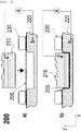
- FIG. 2 is a sectional view of a battery case shaping apparatus 200 according to a first embodiment of the present invention.
- the battery case shaping apparatus 200 includes a punch 210 configured to press a laminate sheet 205 in order to form a battery case; a die 220 having formed therein an accommodation portion corresponding in size to an electrode assembly receiving portion formed by the punch 210; a holder 230 configured to fix the outer edge of the laminate sheet 205; and a current measurement portion A configured to measure current between the punch 210 and the die 220.
- the punch 210 and the die 220 constitute electrodes, and the current measurement portion A is connected to electrode terminals a and b thereof.
- voltage may be applied to measure the current between the punch and the die.
- the current measurement portion A is simply shown in FIGS. 2 to 5 , the current measurement portion may include a portion configured to apply direct-current voltage and an ammeter configured to measure current flowing between a and b after application of voltage, or impedance between a and b may be measured after application of alternating-current voltage.
- the punch 210 and the die 220 must be electrically insulated from each other. At this time, it is preferable for the punch 210 and the holder 230 to also be insulated from each other. The reason for this is that, in a normal case, whether the insulated laminate sheet 205 is abnormal is measured based on the magnitude of current and in that, when the punch 210 and the die 220 are electrically connected to each other, it is difficult to determine whether the laminate sheet 205 is abnormal.
- each of the punch 210 and the holder 230 is not insulated, the punch 210 and the die 220 may be electrically connected to each other due to contact between the punch 210 and the holder 230 and contact between the die 220 and the holder 230. It is preferable for the punch 210 and the holder 230 to be electrically insulated from each other.
- FIG. 2a shows the state before the laminate sheet 205 is pressed using the punch 210
- FIG. 2b shows the state after pressing is performed.
- current or impedance between the electrode terminals a and b may be measured immediately after completion of pressing or shaping, whereby it is possible to immediately determine whether the shaped laminate sheet 205 is abnormal.
- the shaped laminate sheet 205 has a three-dimensional shape, not a planar shape.
- the punch 210 and the die 220 having the two electrode terminals a and b disposed so as to be spaced apart from the entire surface of the shaped laminate sheet 205 by the same distance are used, whereby it is possible to obtain results with high accuracy.
- FIG. 3 is a sectional view of a battery case shaping apparatus 300 according to a second embodiment of the present invention.
- the battery case shaping apparatus 300 of FIG. 3 is configured by adding a conductive elastic separator 335 to the battery case shaping apparatus 200 according to the first embodiment of the present invention of FIG.2 .
- a conductive elastic separator 335 located under the punch 310 may be added, and the conductive elastic separator 335 may be made of a conductive elastic rubber material.
- the conductive elastic separator 335 may be fixed to a lower part of a side surface of a holder 330.
- a liquid lubricant may be added to a space defined by the conductive elastic separator 335 and the holder 330. At this time, the liquid lubricant must be conductive.
- the liquid lubricant remarkably reduces the force of friction between the punch and the conductive elastic separator, whereby the surface of the conductive elastic separator and the surface of the punch may very smoothly slip relative to each other.
- the region of the laminate sheet that is elongated by the punch is increased, and therefore the average elongation of the elongated region may be reduced.
- the thickness of the laminate sheet in an elongated state may be about 70% or more the thickness of the laminate sheet before elongation.
- At least one selected from the group consisting of hydrocarbon-based oil such as liquid paraffin, grease, mineral vegetable oil, an emulsified oil, an anti-emulsifier, a pour point depressant, a viscosity modifier, an antifoaming agent, mineral oil including pure mineral oil or pure mineral oil including an additive, a fatty oil including animal oil and vegetable oil, a blended oil of mineral oil and a fatty oil, and a synthetic oil may be used as the liquid lubricant.
- hydrocarbon-based oil such as liquid paraffin, grease, mineral vegetable oil, an emulsified oil, an anti-emulsifier, a pour point depressant, a viscosity modifier, an antifoaming agent, mineral oil including pure mineral oil or pure mineral oil including an additive, a fatty oil including animal oil and vegetable oil, a blended oil of mineral oil and a fatty oil, and a synthetic oil may be used as the liquid lubricant.
- an ionic material or an ionic liquid may be added
- liquid lubricant used, as described above, it is possible to prevent a local region of the laminate sheet from being excessively elongated.
- the laminate sheet and the punch directly contact each other, slip does not easily occur due to friction between the surfaces of the laminate sheet and the punch. As a result, the region of the laminate sheet that is elongated is narrowed, and therefore only a local region of the laminate sheet is elongated. Specifically, since the portion of the laminate sheet that becomes a side wall of the electrode assembly receiving portion when the laminate sheet is shaped into the battery case is mainly elongated, the thickness of the portion is excessively reduced, and therefore the battery case is easily damaged.
- the laminate sheet Since a stick-slip phenomenon easily occurs on the surface of the laminate sheet and the surface of the punch, as described above, the laminate sheet may be locally excessively elongated, and therefore a battery case shaping defect rate may be increased.
- the laminate sheet 305 is pressed by the punch 310 in the state in which the conductive elastic separator 335 is disposed between the laminate sheet 305 and the punch 310, and therefore the surface of the laminate sheet 305 and the surface of the punch 310 do not directly contact each other. Consequently, it is possible to solve a conventional problem in that the laminate sheet is scratched due to a non-smooth surface of the punch or introduction of foreign matter between the punch and the laminate sheet.
- the elastic separator it is preferable for the elastic separator to be made of a conductive material in order to measure current. If the elastic separator is not made of a conductive material, very high voltage must be applied in order to measure current, which is very dangerous to a person who performs measurement. For this reason, it is preferable for the elastic separator to be conductive.
- the conductive elastic separator may be manufactured by mixing a conventional separator made of an elastic resin or rubber material with a conductive polymer.
- the state in which the conductive elastic separator 335 is fixed to the holder 330 may be stably maintained when the laminate sheet 305 is pressed using the punch 310.
- FIG. 4 is a sectional view of a battery case shaping apparatus 400 according to a third embodiment of the present invention.
- the battery case shaping apparatus 400 is different from the battery case shaping apparatus 200 according to the first embodiment in that voltage is applied between a metal blocking layer 403 of a laminate sheet 405 and a punch 410 to measure current and voltage is applied between the metal blocking layer 410 of the laminate sheet 405 and a die 420 to measure current.
- step S4 which is a step of measuring current while applying voltage
- voltage may be applied between the metal blocking layer of the laminate sheet and the punch to measure current
- voltage may be applied between the metal blocking layer of the laminate sheet and the die to measure current
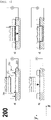
- FIG. 5 shows sectional views of the battery case shaping apparatus according to the first embodiment of the present invention arranged in operation sequence.
- the sequence of FIG. 5 may equally apply to the second embodiment, the third embodiment, or combinations of these embodiments, in addition to the first embodiment.
- a punch pin hole inspection method of a battery cased shaped using the battery case shaping apparatus includes S1) a step of disposing a laminate sheet 205 on a die 220 (see FIG. 5a )); S2) a step of fixing the laminate sheet 205 to the die 220 using a holder 230 (see FIG. 5b )); S3) a step of pressing the laminate sheet 205 using a punch 210 (see FIG. 5c )); and S4) a step of measuring current while applying voltage between the punch 210 and the die 220.
- the punch 210 may simultaneously press the conductive elastic separator and the laminate sheet in step S3).
- voltage may be applied between the metal blocking layer of the laminate sheet and the punch to measure current, and voltage may be applied between the metal blocking layer of the laminate sheet and the die to measure current in step S4, which is the step of measuring current while applying voltage.
- step S4 current may be measured while voltage is changed, or impedance may be measured while applying alternating current.
- step S4) it is preferable to maintain uniform distance between the punch and the die. This means that the punch and the die are spaced apart from each other by a uniform distance at all positions in the state in which the laminate sheet is disposed between the punch and the die. The reason for this is that, only when the punch and the die are spaced apart from each other by a uniform distance, it is possible to check abnormality through flow of current in the entire area.
- step S4) whether punch pin holes are formed may be determined based on whether current flows, and when current flows at a voltage lower than a reference voltage, abnormality of pin holes may be determined.
- the present invention relates to a punch pin hole inspection apparatus using a punch and a die capable of checking defects or damage, specifically pin holes or microcracks, due to shaping immediately after shaping using the punch is finished when a laminate sheet is shaped into a pouch-shaped battery case using the punch and the die and a punch pin hole inspection method using the same, and therefore the present invention has industrial applicability.
Landscapes
- Engineering & Computer Science (AREA)
- Chemical & Material Sciences (AREA)
- Mechanical Engineering (AREA)
- Chemical Kinetics & Catalysis (AREA)
- Electrochemistry (AREA)
- General Chemical & Material Sciences (AREA)
- Manufacturing & Machinery (AREA)
- Inorganic Chemistry (AREA)
- Materials Engineering (AREA)
- Secondary Cells (AREA)
- Sealing Battery Cases Or Jackets (AREA)
Abstract
Description
- This application claims the benefit of priority to
Korean Patent Application No. 2020-0155805 filed on November 19, 2020 - The present invention relates to a punch pin hole inspection apparatus using a punch and a die and a punch pin hole inspection method using the same. More particularly, the present invention relates to a punch pin hole inspection apparatus using a punch and a die capable of checking defects or damage due to shaping immediately after finishing shaping using the punch to shape a pouch-shaped battery case using the punch and the die and a punch pin hole inspection method using the same.
- Demand for a secondary battery as an energy source for mobile devices, electric vehicles, etc. has abruptly increased. In particular, demand for a lithium secondary battery, which has high energy density and high discharge voltage, is high.
- Based on the shape and material thereof, the lithium secondary battery may be classified as a cylindrical secondary battery made of a metal material, a prismatic secondary battery made of a metal material, or a pouch-shaped secondary battery made of a laminate sheet. The pouch-shaped secondary battery has advantages in that the pouch-shaped secondary battery is stacked with high integrity, thereby having high energy density per unit weight, is manufactured at low cost, and is easily deformable. Consequently, the pouch-shaped secondary battery is used in various devices.
- For the pouch-shaped secondary battery, a laminate sheet including an outer coating layer, a metal blocking layer, and an inner adhesive layer is shaped so as to be used as a battery case. An electrode assembly is received in a receiving portion formed in the laminate sheet together with an electrolytic solution, and the receiving portion is hermetically sealed, whereby the pouch-shaped secondary battery is manufactured.
- In order to shape the laminate sheet to form an electrode assembly receiving portion, a deep drawing method of disposing the laminate sheet on a die, fixing the laminated sheet, and pressing the laminate sheet using a punch in the state in which the laminate sheet is fixed using a holder is used. During deep drawing, however, defects or damage, such as pin holes or cracks, may be formed in the outer coating layer or the metal blocking layer of the laminate sheet due to limited softness of the laminate sheet and the force of friction between the punch and the laminate sheet.
- Even though surface roughness of the punch that contacts the laminate sheet is extremely reduced in order to prevent such external defects, it is difficult to prevent external defects from being formed on the laminate sheet due to friction caused by repeated punching. Particularly, in the case in which the thickness of the laminate sheet, specifically the metal blocking layer, is small, shapeability of the laminate sheet is reduced, whereby pin holes or cracks may be more easily formed.
- A case having defects, such as pin holes, must be removed by sorting; however, it is not easy to sense micro-scale pin holes, which are difficult to observe with the naked eye.
- Patent Document 1 relates to a hot-pressed product manufacturing method and a hot-pressed product, wherein hot pressing is performed on a surface-treated steel sheet having an Zn-Ni plating layer formed on the surface of a base steel sheet using a press having a die, a blank holder, and a punch, in order to manufacture a hot-pressed product. The edge of the surface-treated steel sheet heated to a temperature between the Ac3 transformation point and 1000°C is cooled down to a temperature of 550°C to 400°C at a cooling speed of 100°C/s in a state of being disposed between the die and the blank holder, pressing is commenced when the temperature of the edge is 550°C to 400°C, and a pressed body is maintained at a pressing bottom dead center in a state of being disposed in the press such that the pressed body is rapidly cooled after pressing.
- Patent Document 1 discloses that whether microcracks are formed is checked in hot pressing using the punch and the die, which is different from the present invention in that the section of a pressed product is checked using a scanning electron microscope. In the case in which the section of the pressed product is checked using a visual method, as in Patent Document 1, too much time is taken, and therefore this method is not suitable for mass production of a laminate sheet for pouch-shaped batteries.
- Patent Document 2 relates to a device for detecting pin holes in manufacturing an aramid film.
- Patent Document 2 discloses a method of disposing electrodes at opposite surfaces of a film that is continuously conveyed, applying voltage, and detecting current therefor to check whether pin holes are formed on the film. Patent Document 2 is applied to a material that is continuously conveyed in a roll shape, such as film or fiber, which is different from a method according to the present invention of applying voltage between a punch and a die without movement of the punch after a pressed body is completed.
- Patent Document 3 relates to a press workability evaluation apparatus and a press workability evaluation method, wherein a punch having a multi-branch-shaped convex portion having three or more branches, a die having a concave portion fitted to the convex portion and a die-side planar portion surrounding the concave portion, and a pressing plate having a pressing plate-side planar portion almost parallel to the die-side planar portion are included, and a target material to be pressed is inserted between the die-side planar portion and the pressing plate-side planar portion.
- Patent Document 3 discloses that variation, cracks, or breakage of a pressed body is detected in a pressing process using the punch and the die, which is different in fundamental mechanism from the present invention, which measures current, in that marks are transferred to a target material to be pressed, images are captured using a CCD camera before and after processing based on each mark, and the distance between the marks before and after processing is measured to calculate variation. Since Patent Document 3 uses visual materials, application to a laminate sheet having high reflectivity is difficult, and visual analysis is performed over the entire area, whereby rapid detection is impossible.
- Patent Document 4 relates to a method of detecting abnormality of a thin plate pressing apparatus, wherein when a thin plate is pressed through relative movement between a punch and a die, at least one of the punch and the die is a press to be measured, and elastic deformation occurring in the press to be measured by pressing, measured by a deformation measurement means installed in the press to be measured, is greater than or less than a predetermined range, pressing abnormality is determined.
- Patent Document 4 is different in measurement mechanism from the present invention in that a measurement means, such as a piezoelectric element or a strain gauge, is provided in the punch in order to detect deformation of the punch. Patent Document 4 is used for a metal material, such as a vehicle plate, and when this document is applied to an apparatus that uses current, there may be no discrimination depending on abnormality or not.
- A pin hole inspection method that is efficient while being suitable for the characteristics of a laminate sheet used for a battery case has not yet been suggested.
-
Korean Patent Application Publication No. 2016-0130831 (2016.11.14 - International Publication No.
1999-008853 (1999.02.25 ) ("Patent Document 2") -
Japanese Patent Application Publication No. 2016-144824 (2016.08.12 -
Japanese Patent Application Publication No. 2008- 264849 (2008.11.06 - The present invention has been made in view of the above problems, and it is an object of the present invention to provide a punch pin hole inspection apparatus using a punch and a die capable of checking defects or damage, specifically pin holes or microcracks, due to shaping immediately after finishing shaping using the punch to shape a laminate sheet into a pouch-shaped battery case using the punch and the die and a punch pin hole inspection method using the same.
- In order to accomplish the above object, the present invention provides a battery case shaping apparatus including a punch configured to press a laminate sheet in order to form a battery case; a die forming an accommodation portion corresponding in size to an electrode assembly receiving portion formed by the punch; a holder configured to fix the outer edge of the laminate sheet; and a current measurement portion configured to measure current between the punch and the die.
- The punch and the die may constitute electrodes, and, when the laminate sheet is disposed between the punch and the die, the current measurement portion may apply voltage to measure the current value between the punch and the die.
- In the case in which the laminate sheet is disposed, the punch and the die must be electrically insulated from each other. At this time, it is preferable for the punch and the holder to also be insulated from each other.
- A conductive elastic separator located under the punch may be included to prevent direct contact between the punch and the laminate sheet. The conductive elastic separator may be made of a conductive elastic rubber material. The conductive elastic separator may be fixed to a lower part of a side surface of the holder. A liquid lubricant may be added to a space defined by the conductive elastic separator and the holder. At this time, the lubricant must be conductive.
- In addition, the present invention provides a punch pin hole inspection method of a battery case shaped using the battery case shaping apparatus, the punch pin hole inspection method including S1) disposing a laminate sheet on a die, S2) fixing the laminate sheet to the die using a holder, S3) pressing the elastic separator and the laminate sheet using a punch, and S4) measuring current while applying voltage between the punch and the die.
- In step S4), current may be measured while voltage is changed.
- Step S4) of measuring current while applying voltage may be replaced by a step of measuring impedance while applying alternating current.
- Step S4) of measuring current while applying voltage may be replaced by a step of applying voltage between a metal blocking layer of the laminate sheet and the punch to measure current and applying voltage between a metal blocking layer of the laminate sheet and the die to measure current.
- In step S4), uniform distance may be maintained between the punch and the die. This means that the punch and the die are spaced apart from each other by a uniform distance at all positions in the state in which the laminate sheet is disposed between the punch and the die. Only when the punch and the die are spaced apart from each other by a uniform distance, it is possible to check abnormality through flow of current in the entire area.
- In step S4), whether punch pin holes are formed may be determined based on whether current flows. At this time, when current flows at a voltage lower than a reference voltage, abnormality of pin holes may be determined.
- In addition, the present invention may provide all possible combinations of the above solving means.
- As is apparent from the above description, in the present invention, current is measured using a current measurement portion configured to measure current between a punch and a die, whereby it is possible to check defects or damage, specifically pin holes or microcracks, due to shaping immediately after shaping using the punch is finished.
- In the present invention, two electrodes, i.e. the punch and the die, are disposed so as to be spaced apart from the entire surface of a laminate sheet having a three-dimensional shape, not a planar shape, by the same distance, and current is applied immediately after shaping is finished, whereby it is possible to perform uniform inspection on the entire surface of the shaped laminate sheet.
- Also, in the present invention, a conductive elastic separator is disposed under the punch in order to prevent direct contact between the punch and the laminate sheet, whereby it is possible to prevent excessive mechanical stress due to the punch from being transferred to the laminate sheet. In addition, current is measured in the state in which stress is relieved, whereby it is possible to avoid an error problem in measurement.
- In the present invention, an electrode assembly receiving portion is formed by shaping in the state in which the conductive elastic separator is interposed between the laminate sheet and the punch, whereby it is possible to prevent the punch from directly contacting the laminate sheet, and therefore it is possible to minimize a stick-slip effect that occurs on the surface of the punch and the surface of the laminate sheet.
- In addition, a liquid lubricant is added between the punch and the conductive elastic separator, whereby it is possible to reduce the force of friction between the punch and the laminate sheet.
- In addition, it is possible to enlarge an elongated region of the laminate sheet due to addition of the liquid lubricant and the conductive elastic separator, whereby it is possible to prevent the laminate sheet from being locally excessively elongated and thus thinned.
- In addition, when the battery case shaping apparatus and method according to the present invention are used even though laminate sheets having the same thickness are used, it is possible to more deeply form the electrode assembly receiving portion, whereby it is possible to increase capacity of a battery cell and to improve energy density of the battery cell.
-
-
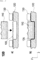
FIG. 1 is a cross-sectional view of a conventional battery case shaping apparatus. -
FIG. 2 is a cross-sectional view of a battery case shaping apparatus according to a first embodiment of the present invention. -
FIG. 3 is a cross-sectional view of a battery case shaping apparatus according to a second embodiment of the present invention. -
FIG. 4 is a cross-sectional view of a battery case shaping apparatus according to a third embodiment of the present invention. -
FIG. 5 shows cross-sectional views of the battery case shaping apparatus according to the first embodiment of the present invention arranged in operation sequence. - Now, preferred embodiments of the present invention will be described in detail with reference to the accompanying drawings such that the preferred embodiments of the present invention can be easily implemented by a person having ordinary skill in the art to which the present invention pertains. In describing the principle of operation of the preferred embodiments of the present invention in detail, however, a detailed description of known functions and configurations incorporated herein will be omitted when the same may obscure the subject matter of the present invention.
- In addition, the same reference numbers will be used throughout the drawings to refer to parts that perform similar functions or operations. In the case in which one part is said to be connected to another part throughout the specification, not only may the one part be directly connected to the other part, but also, the one part may be indirectly connected to the other part via a further part. In addition, that a certain element is included does not mean that other elements are excluded but means that such elements may be further included unless mentioned otherwise.
- In addition, a description to embody elements through limitation or addition may be applied to all inventions, unless particularly restricted, and does not limit a specific invention.
- Also, in the description of the invention and the claims of the present application, singular forms are intended to include plural forms unless mentioned otherwise.
- Also, in the description of the invention and the claims of the present application, "or" includes "and" unless mentioned otherwise. Therefore, "including A or B" means three cases, namely, the case including A, the case including B, and the case including A and B.
- A laminate sheet used as a case of a pouch-shaped battery is basically an insulator. In general, a laminate sheet including an outer coating layer, a metal blocking layer, and an inner adhesive layer exhibits insulation characteristics. During shaping thereof, however, defects or damage, such as pin holes or cracks, are formed in the outer coating layer or the metal blocking layer of the laminate sheet, whereby the insulation characteristics of the laminate sheet are deteriorated.
- When the laminate sheet is not abnormal, on the other hand, the insulation characteristics of the laminate sheet are maintained. Consequently, it is possible to determine whether the laminate sheet is abnormal through measurement of the insulation characteristics of the laminate sheet. In the case in which the extent or size of defects or damage, such as pin holes or cracks, is small, current having discrimination thereon is generated only when high voltage is applied between two electrodes spaced apart from each other by a uniform distance.
- The shaped laminate sheet has a three-dimensional shape, not a planar shape. For accurate detection, therefore, the two electrodes must be disposed so as to be spaced apart from the entire surface of the shaped laminate sheet by the same distance.
- In many cases, a punch and a die used for shaping are made of a metal material, and the punch and the die have the same shape as the shaped laminate sheet. Consequently, the present invention has been derived in consideration of the fact that, when the punch and the die are used as electrodes, it is possible to accurately detect whether the entire surface of the shaped laminate sheet is abnormal.
- Hereinafter, embodiments of the present invention will be described in detail with reference to the accompanying drawings.
-
FIG. 2 is a sectional view of a batterycase shaping apparatus 200 according to a first embodiment of the present invention. - Referring to
FIG. 2 , the batterycase shaping apparatus 200 according to the first embodiment of the present invention includes apunch 210 configured to press alaminate sheet 205 in order to form a battery case; adie 220 having formed therein an accommodation portion corresponding in size to an electrode assembly receiving portion formed by thepunch 210; aholder 230 configured to fix the outer edge of thelaminate sheet 205; and a current measurement portion A configured to measure current between thepunch 210 and thedie 220. - The
punch 210 and thedie 220 constitute electrodes, and the current measurement portion A is connected to electrode terminals a and b thereof. When thelaminate sheet 205 is disposed between thepunch 210 and thedie 220, voltage may be applied to measure the current between the punch and the die. Although the current measurement portion A is simply shown inFIGS. 2 to 5 , the current measurement portion may include a portion configured to apply direct-current voltage and an ammeter configured to measure current flowing between a and b after application of voltage, or impedance between a and b may be measured after application of alternating-current voltage. - In the case in which the
laminate sheet 205 is disposed, thepunch 210 and thedie 220 must be electrically insulated from each other. At this time, it is preferable for thepunch 210 and theholder 230 to also be insulated from each other. The reason for this is that, in a normal case, whether theinsulated laminate sheet 205 is abnormal is measured based on the magnitude of current and in that, when thepunch 210 and thedie 220 are electrically connected to each other, it is difficult to determine whether thelaminate sheet 205 is abnormal. Furthermore, if each of thepunch 210 and theholder 230 is not insulated, thepunch 210 and thedie 220 may be electrically connected to each other due to contact between thepunch 210 and theholder 230 and contact between the die 220 and theholder 230. It is preferable for thepunch 210 and theholder 230 to be electrically insulated from each other. -
FIG. 2a ) shows the state before thelaminate sheet 205 is pressed using thepunch 210, andFIG. 2b ) shows the state after pressing is performed. In the present invention, current or impedance between the electrode terminals a and b may be measured immediately after completion of pressing or shaping, whereby it is possible to immediately determine whether the shapedlaminate sheet 205 is abnormal. - The shaped
laminate sheet 205 has a three-dimensional shape, not a planar shape. For accurate detection, therefore, thepunch 210 and thedie 220 having the two electrode terminals a and b disposed so as to be spaced apart from the entire surface of the shapedlaminate sheet 205 by the same distance are used, whereby it is possible to obtain results with high accuracy. -
FIG. 3 is a sectional view of a batterycase shaping apparatus 300 according to a second embodiment of the present invention. The batterycase shaping apparatus 300 ofFIG. 3 is configured by adding a conductiveelastic separator 335 to the batterycase shaping apparatus 200 according to the first embodiment of the present invention ofFIG.2 . - In order to prevent direct contact between a
punch 310 and alaminate sheet 305, a conductiveelastic separator 335 located under thepunch 310 may be added, and the conductiveelastic separator 335 may be made of a conductive elastic rubber material. The conductiveelastic separator 335 may be fixed to a lower part of a side surface of aholder 330. A liquid lubricant may be added to a space defined by the conductiveelastic separator 335 and theholder 330. At this time, the liquid lubricant must be conductive. - The liquid lubricant remarkably reduces the force of friction between the punch and the conductive elastic separator, whereby the surface of the conductive elastic separator and the surface of the punch may very smoothly slip relative to each other.
- As a result, the region of the laminate sheet that is elongated by the punch is increased, and therefore the average elongation of the elongated region may be reduced. For example, the thickness of the laminate sheet in an elongated state may be about 70% or more the thickness of the laminate sheet before elongation.
- For example, at least one selected from the group consisting of hydrocarbon-based oil, such as liquid paraffin, grease, mineral vegetable oil, an emulsified oil, an anti-emulsifier, a pour point depressant, a viscosity modifier, an antifoaming agent, mineral oil including pure mineral oil or pure mineral oil including an additive, a fatty oil including animal oil and vegetable oil, a blended oil of mineral oil and a fatty oil, and a synthetic oil may be used as the liquid lubricant. In order to secure conductivity, an ionic material or an ionic liquid may be added.
- In the case in which the liquid lubricant is used, as described above, it is possible to prevent a local region of the laminate sheet from being excessively elongated.
- If the laminate sheet and the punch directly contact each other, slip does not easily occur due to friction between the surfaces of the laminate sheet and the punch. As a result, the region of the laminate sheet that is elongated is narrowed, and therefore only a local region of the laminate sheet is elongated. Specifically, since the portion of the laminate sheet that becomes a side wall of the electrode assembly receiving portion when the laminate sheet is shaped into the battery case is mainly elongated, the thickness of the portion is excessively reduced, and therefore the battery case is easily damaged.
- Since a stick-slip phenomenon easily occurs on the surface of the laminate sheet and the surface of the punch, as described above, the laminate sheet may be locally excessively elongated, and therefore a battery case shaping defect rate may be increased.
- In the present invention, the
laminate sheet 305 is pressed by thepunch 310 in the state in which the conductiveelastic separator 335 is disposed between thelaminate sheet 305 and thepunch 310, and therefore the surface of thelaminate sheet 305 and the surface of thepunch 310 do not directly contact each other. Consequently, it is possible to solve a conventional problem in that the laminate sheet is scratched due to a non-smooth surface of the punch or introduction of foreign matter between the punch and the laminate sheet. - However, it is preferable for the elastic separator to be made of a conductive material in order to measure current. If the elastic separator is not made of a conductive material, very high voltage must be applied in order to measure current, which is very dangerous to a person who performs measurement. For this reason, it is preferable for the elastic separator to be conductive. The conductive elastic separator may be manufactured by mixing a conventional separator made of an elastic resin or rubber material with a conductive polymer.
- Since the conductive
elastic separator 335 is fixed to theholder 330, the state in which the conductiveelastic separator 335 is fixed to theholder 330 may be stably maintained when thelaminate sheet 305 is pressed using thepunch 310. -
FIG. 4 is a sectional view of a batterycase shaping apparatus 400 according to a third embodiment of the present invention. - The battery
case shaping apparatus 400 is different from the batterycase shaping apparatus 200 according to the first embodiment in that voltage is applied between ametal blocking layer 403 of alaminate sheet 405 and apunch 410 to measure current and voltage is applied between themetal blocking layer 410 of thelaminate sheet 405 and adie 420 to measure current. - In the case in which whether the
laminate sheet 405 is abnormal is measured using the batterycase shaping apparatus 400 according to the third embodiment of the present invention, it is possible to accurately check which surface of thelaminate sheet 405, i.e. which of anouter coating layer 402 and an inneradhesive layer 404, is damaged, whereby it is possible to minutely check whether the apparatus is abnormal. - In step S4, which is a step of measuring current while applying voltage, voltage may be applied between the metal blocking layer of the laminate sheet and the punch to measure current, and voltage may be applied between the metal blocking layer of the laminate sheet and the die to measure current.
- In the first embodiment, the second embodiment, and the third embodiment of the present invention, only characteristic parts are emphasized, and therefore these embodiments may be combined with each other. For example, the second embodiment and the third embodiment may be combined with each other.
-
FIG. 5 shows sectional views of the battery case shaping apparatus according to the first embodiment of the present invention arranged in operation sequence. The sequence ofFIG. 5 may equally apply to the second embodiment, the third embodiment, or combinations of these embodiments, in addition to the first embodiment. - A punch pin hole inspection method of a battery cased shaped using the battery case shaping apparatus includes S1) a step of disposing a
laminate sheet 205 on a die 220 (seeFIG. 5a )); S2) a step of fixing thelaminate sheet 205 to the die 220 using a holder 230 (seeFIG. 5b )); S3) a step of pressing thelaminate sheet 205 using a punch 210 (seeFIG. 5c )); and S4) a step of measuring current while applying voltage between thepunch 210 and thedie 220. - For the second embodiment, in which the conductive elastic separator is added, the
punch 210 may simultaneously press the conductive elastic separator and the laminate sheet in step S3). For the third embodiment, voltage may be applied between the metal blocking layer of the laminate sheet and the punch to measure current, and voltage may be applied between the metal blocking layer of the laminate sheet and the die to measure current in step S4, which is the step of measuring current while applying voltage. - Meanwhile, in step S4), current may be measured while voltage is changed, or impedance may be measured while applying alternating current.
- In step S4), it is preferable to maintain uniform distance between the punch and the die. This means that the punch and the die are spaced apart from each other by a uniform distance at all positions in the state in which the laminate sheet is disposed between the punch and the die. The reason for this is that, only when the punch and the die are spaced apart from each other by a uniform distance, it is possible to check abnormality through flow of current in the entire area.
- In step S4), whether punch pin holes are formed may be determined based on whether current flows, and when current flows at a voltage lower than a reference voltage, abnormality of pin holes may be determined.
- Those skilled in the art to which the present invention pertains will appreciate that various applications and modifications are possible within the category of the present invention based on the above description.
-
- 100, 200, 300, 400: Battery case manufacturing apparatuses
- 105, 205, 305, 405: Laminate sheets
- 402: Outer coating layer
- 430: Metal blocking layer
- 404: Inner adhesive layer
- 110, 210, 310, 410: Punches
- 120, 220, 320, 420: Dies
- 130, 230, 330, 430: Holders
- 335: Elastic separator
- a, b, c: Electrode terminals
- A: Ammeter
- The present invention relates to a punch pin hole inspection apparatus using a punch and a die capable of checking defects or damage, specifically pin holes or microcracks, due to shaping immediately after shaping using the punch is finished when a laminate sheet is shaped into a pouch-shaped battery case using the punch and the die and a punch pin hole inspection method using the same, and therefore the present invention has industrial applicability.
Claims (13)
- A battery case shaping apparatus comprising:a punch configured to press a laminate sheet in order to form a battery case;a die forming an accommodation portion corresponding in size to an electrode assembly receiving portion formed by the punch;a holder configured to fix an outer edge of the laminate sheet; anda current measurement portion configured to measure current between the punch and the die.
- The battery case shaping apparatus according to claim 1, wherein the punch and the die constitute electrodes, and
wherein, when the laminate sheet is disposed between the punch and the die, the current measurement portion applies voltage to measure the current between the punch and the die. - The battery case shaping apparatus according to claim 2, wherein, when the laminate sheet is disposed, the punch and the die are electrically insulated from each other.
- The battery case shaping apparatus according to claim 2, further comprising a conductive elastic separator located under the punch and configured to prevent direct contact between the punch and the laminate sheet.
- The battery case shaping apparatus according to claim 4, wherein the conductive elastic separator is made of a conductive elastic rubber material.
- The battery case shaping apparatus according to claim 4, wherein the conductive elastic separator is fixed to a lower part of a side surface of the holder.
- A punch pin hole inspection method of a battery case shaped using the battery case shaping apparatus according to any one of claims 1 to 6, the punch pin hole inspection method comprising:S1) disposing a laminate sheet on a die;S2) fixing the laminate sheet to the die using a holder;S3) pressing the laminate sheet using a punch; andS4) measuring current while applying voltage between the punch and the die.
- The punch pin hole inspection method according to claim 7, wherein, in step S4), current is measured while voltage is changed.
- The punch pin hole inspection method according to claim 7, wherein step S4) of measuring current while applying voltage is replaced by a step of measuring impedance while applying alternating current.
- The punch pin hole inspection method according to claim 7, wherein step S4) of measuring current while applying voltage is replaced by a step of applying voltage between a metal blocking layer of the laminate sheet and the punch to measure current and applying voltage between a metal blocking layer of the laminate sheet and the die to measure current.
- The punch pin hole inspection method according to claim 7, wherein, in step S4), uniform distance is maintained between the punch and the die.
- The punch pin hole inspection method according to claim 7, wherein, in step S4), whether punch pin holes are formed is determined based on whether current flows.
- The punch pin hole inspection method according to claim 12, wherein, when current flows at a voltage lower than a reference voltage, abnormality of pin holes is determined.
Applications Claiming Priority (2)
| Application Number | Priority Date | Filing Date | Title |
|---|---|---|---|
| KR1020200155805A KR102949124B1 (en) | 2020-11-19 | 2020-11-19 | Punch pin hole inspection device using punch and die, and punch pin hole inspection method using the same |
| PCT/KR2021/015839 WO2022108196A1 (en) | 2020-11-19 | 2021-11-04 | Punch pin hole inspection apparatus using punch and die, and punch pin hole inspection method using same |
Publications (3)
| Publication Number | Publication Date |
|---|---|
| EP4112271A1 true EP4112271A1 (en) | 2023-01-04 |
| EP4112271A4 EP4112271A4 (en) | 2023-10-25 |
| EP4112271B1 EP4112271B1 (en) | 2024-08-21 |
Family
ID=81709216
Family Applications (1)
| Application Number | Title | Priority Date | Filing Date |
|---|---|---|---|
| EP21894967.5A Active EP4112271B1 (en) | 2020-11-19 | 2021-11-04 | Punch pin hole inspection apparatus using punch and die, and punch pin hole inspection method using same |
Country Status (7)
| Country | Link |
|---|---|
| US (1) | US12042976B2 (en) |
| EP (1) | EP4112271B1 (en) |
| KR (1) | KR102949124B1 (en) |
| ES (1) | ES2993414T3 (en) |
| HU (1) | HUE068444T2 (en) |
| PL (1) | PL4112271T3 (en) |
| WO (1) | WO2022108196A1 (en) |
Family Cites Families (11)
| Publication number | Priority date | Publication date | Assignee | Title |
|---|---|---|---|---|
| JP3575543B2 (en) | 1997-08-14 | 2004-10-13 | 旭化成ケミカルズ株式会社 | Aramid film roll and its pinhole detection |
| JP5194540B2 (en) | 2007-04-23 | 2013-05-08 | 新日鐵住金株式会社 | Abnormality detection method for thin plate press die equipment |
| JP5596647B2 (en) | 2010-10-13 | 2014-09-24 | 株式会社ソーデナガノ | Battery case lid manufacturing method |
| CN104624848B (en) | 2010-10-13 | 2017-01-18 | 早出长野股份有限公司 | Battery case lid and manufacturing method for battery case lid |
| JP5825413B1 (en) | 2014-04-23 | 2015-12-02 | Jfeスチール株式会社 | Manufacturing method of hot press-formed product |
| KR20160036435A (en) | 2014-09-25 | 2016-04-04 | 현대제철 주식회사 | Press molding apparatus |
| JP6173369B2 (en) | 2015-02-09 | 2017-08-02 | 日新製鋼株式会社 | Press workability evaluation apparatus and press workability evaluation method |
| KR102104310B1 (en) | 2016-01-26 | 2020-04-24 | 주식회사 엘지화학 | Manufacturing Apparatus for Battery Case Capable of Mounting Electrode Assembly of High Capacity Therein |
| KR102246095B1 (en) | 2016-10-07 | 2021-04-29 | 주식회사 엘지화학 | Method of Manufacturing Battery Case Using Film Member for Forming |
| KR102013926B1 (en) | 2018-01-05 | 2019-08-23 | 한국기계연구원 | Electroplastic forming method |
| CN111864160A (en) | 2019-04-25 | 2020-10-30 | 住友化学株式会社 | Diaphragm manufacturing method and diaphragm manufacturing apparatus |
-
2020
- 2020-11-19 KR KR1020200155805A patent/KR102949124B1/en active Active
-
2021
- 2021-11-04 PL PL21894967.5T patent/PL4112271T3/en unknown
- 2021-11-04 HU HUE21894967A patent/HUE068444T2/en unknown
- 2021-11-04 EP EP21894967.5A patent/EP4112271B1/en active Active
- 2021-11-04 ES ES21894967T patent/ES2993414T3/en active Active
- 2021-11-04 US US17/926,470 patent/US12042976B2/en active Active
- 2021-11-04 WO PCT/KR2021/015839 patent/WO2022108196A1/en not_active Ceased
Also Published As
| Publication number | Publication date |
|---|---|
| PL4112271T3 (en) | 2025-01-13 |
| ES2993414T3 (en) | 2024-12-30 |
| KR102949124B1 (en) | 2026-04-07 |
| US20230182370A1 (en) | 2023-06-15 |
| WO2022108196A1 (en) | 2022-05-27 |
| CN115461208A (en) | 2022-12-09 |
| KR20220069178A (en) | 2022-05-27 |
| US12042976B2 (en) | 2024-07-23 |
| HUE068444T2 (en) | 2024-12-28 |
| EP4112271A4 (en) | 2023-10-25 |
| EP4112271B1 (en) | 2024-08-21 |
Similar Documents
| Publication | Publication Date | Title |
|---|---|---|
| KR102798449B1 (en) | Method for evaluating physical properties of thin film specimens and thin film specimen for tensile test | |
| EP3644390A1 (en) | Pouch manufacturing device and method, and secondary battery manufacturing method | |
| KR102303643B1 (en) | Inspection device and method for detecting air void at the lead film of battery | |
| EP3531107B1 (en) | Jig assembly comprising bending jig and apparatus and method for measurng bending tensile strenght using the same | |
| Zhang et al. | Investigation of material failure in micro-stamping of metallic bipolar plates | |
| CN110740821B (en) | Evaluation method of deformation limit of metal plate in shearing plane, crack prediction method and design method of stamping metal die | |
| JP2022148114A (en) | Material evaluation method and manufacturing method for metal member | |
| US11493316B2 (en) | Apparatus for measuring thickness of battery materials | |
| EP4112271B1 (en) | Punch pin hole inspection apparatus using punch and die, and punch pin hole inspection method using same | |
| JP7388201B2 (en) | Stress evaluation method, bending workability evaluation method, and metal member manufacturing method | |
| Furushima et al. | Fracture and surface roughening behaviors in micro metal forming | |
| CN115461208B (en) | A punch hole inspection device using punches and dies, and a punch hole inspection method using the device. | |
| US12281894B2 (en) | Welding rod inspection apparatus for measuring whether welding rod is normal and inspection method using the same | |
| EP4439776A1 (en) | Pouch cell deformation inspection device and deformation inspection method using same | |
| Ma et al. | Microdeep drawing of C1100 microsquare cups using microforming technology | |
| JP6173369B2 (en) | Press workability evaluation apparatus and press workability evaluation method | |
| JP7730306B2 (en) | Sheet metal forming limit evaluation method and crack prediction method | |
| JP2024142837A (en) | METHOD AND APPARATUS FOR EVALUATING METAL PLATE MATERIAL | |
| Lee et al. | Effect of thickness to grain size ratio on drawability for micro deep drawing of AISI 304 stainless steel | |
| Olayinka et al. | The effect of hydraulic bulge process on the surface topography of annealed AISI 304 stainless steel | |
| JP2023147797A (en) | Test equipment and test method | |
| Rękas et al. | The analysis of mechanical properties of 3XXX series aluminum sheets used for beverage can production | |
| CN111537437B (en) | Bending die operation method for graded inspection of DP980 high-strength steel adhesive force | |
| RU2621324C2 (en) | Procedure for assessment of ability of flats to stamping | |
| CN114659893B (en) | A plate and pipe compression performance testing device and method |
Legal Events
| Date | Code | Title | Description |
|---|---|---|---|
| STAA | Information on the status of an ep patent application or granted ep patent |
Free format text: STATUS: THE INTERNATIONAL PUBLICATION HAS BEEN MADE |
|
| PUAI | Public reference made under article 153(3) epc to a published international application that has entered the european phase |
Free format text: ORIGINAL CODE: 0009012 |
|
| STAA | Information on the status of an ep patent application or granted ep patent |
Free format text: STATUS: REQUEST FOR EXAMINATION WAS MADE |
|
| 17P | Request for examination filed |
Effective date: 20220930 |
|
| AK | Designated contracting states |
Kind code of ref document: A1 Designated state(s): AL AT BE BG CH CY CZ DE DK EE ES FI FR GB GR HR HU IE IS IT LI LT LU LV MC MK MT NL NO PL PT RO RS SE SI SK SM TR |
|
| A4 | Supplementary search report drawn up and despatched |
Effective date: 20230922 |
|
| RIC1 | Information provided on ipc code assigned before grant |
Ipc: B29C 43/58 20060101ALI20230918BHEP Ipc: B29C 51/46 20060101ALI20230918BHEP Ipc: B29C 51/26 20060101ALI20230918BHEP Ipc: B29C 43/36 20060101ALI20230918BHEP Ipc: B29C 51/14 20060101ALI20230918BHEP Ipc: H01M 50/124 20210101ALI20230918BHEP Ipc: H01M 50/116 20210101ALI20230918BHEP Ipc: B29C 51/08 20060101AFI20230918BHEP |
|
| DAV | Request for validation of the european patent (deleted) | ||
| DAX | Request for extension of the european patent (deleted) | ||
| GRAP | Despatch of communication of intention to grant a patent |
Free format text: ORIGINAL CODE: EPIDOSNIGR1 |
|
| STAA | Information on the status of an ep patent application or granted ep patent |
Free format text: STATUS: GRANT OF PATENT IS INTENDED |
|
| INTG | Intention to grant announced |
Effective date: 20240604 |
|
| GRAS | Grant fee paid |
Free format text: ORIGINAL CODE: EPIDOSNIGR3 |
|
| GRAA | (expected) grant |
Free format text: ORIGINAL CODE: 0009210 |
|
| STAA | Information on the status of an ep patent application or granted ep patent |
Free format text: STATUS: THE PATENT HAS BEEN GRANTED |
|
| P01 | Opt-out of the competence of the unified patent court (upc) registered |
Free format text: CASE NUMBER: APP_39360/2024 Effective date: 20240702 |
|
| AK | Designated contracting states |
Kind code of ref document: B1 Designated state(s): AL AT BE BG CH CY CZ DE DK EE ES FI FR GB GR HR HU IE IS IT LI LT LU LV MC MK MT NL NO PL PT RO RS SE SI SK SM TR |
|
| REG | Reference to a national code |
Ref country code: GB Ref legal event code: FG4D |
|
| REG | Reference to a national code |
Ref country code: CH Ref legal event code: EP |
|
| REG | Reference to a national code |
Ref country code: IE Ref legal event code: FG4D |
|
| REG | Reference to a national code |
Ref country code: DE Ref legal event code: R096 Ref document number: 602021017703 Country of ref document: DE |
|
| REG | Reference to a national code |
Ref country code: SE Ref legal event code: TRGR |
|
| REG | Reference to a national code |
Ref country code: LT Ref legal event code: MG9D |
|
| REG | Reference to a national code |
Ref country code: HU Ref legal event code: AG4A Ref document number: E068444 Country of ref document: HU |
|
| REG | Reference to a national code |
Ref country code: ES Ref legal event code: FG2A Ref document number: 2993414 Country of ref document: ES Kind code of ref document: T3 Effective date: 20241230 |
|
| REG | Reference to a national code |
Ref country code: NL Ref legal event code: MP Effective date: 20240821 |
|
| PG25 | Lapsed in a contracting state [announced via postgrant information from national office to epo] |
Ref country code: NO Free format text: LAPSE BECAUSE OF FAILURE TO SUBMIT A TRANSLATION OF THE DESCRIPTION OR TO PAY THE FEE WITHIN THE PRESCRIBED TIME-LIMIT Effective date: 20241121 |
|
| REG | Reference to a national code |
Ref country code: AT Ref legal event code: MK05 Ref document number: 1715136 Country of ref document: AT Kind code of ref document: T Effective date: 20240821 |
|
| PG25 | Lapsed in a contracting state [announced via postgrant information from national office to epo] |
Ref country code: PT Free format text: LAPSE BECAUSE OF FAILURE TO SUBMIT A TRANSLATION OF THE DESCRIPTION OR TO PAY THE FEE WITHIN THE PRESCRIBED TIME-LIMIT Effective date: 20241223 Ref country code: FI Free format text: LAPSE BECAUSE OF FAILURE TO SUBMIT A TRANSLATION OF THE DESCRIPTION OR TO PAY THE FEE WITHIN THE PRESCRIBED TIME-LIMIT Effective date: 20240821 Ref country code: NL Free format text: LAPSE BECAUSE OF FAILURE TO SUBMIT A TRANSLATION OF THE DESCRIPTION OR TO PAY THE FEE WITHIN THE PRESCRIBED TIME-LIMIT Effective date: 20240821 Ref country code: GR Free format text: LAPSE BECAUSE OF FAILURE TO SUBMIT A TRANSLATION OF THE DESCRIPTION OR TO PAY THE FEE WITHIN THE PRESCRIBED TIME-LIMIT Effective date: 20241122 |
|
| PG25 | Lapsed in a contracting state [announced via postgrant information from national office to epo] |
Ref country code: BG Free format text: LAPSE BECAUSE OF FAILURE TO SUBMIT A TRANSLATION OF THE DESCRIPTION OR TO PAY THE FEE WITHIN THE PRESCRIBED TIME-LIMIT Effective date: 20240821 |
|
| PG25 | Lapsed in a contracting state [announced via postgrant information from national office to epo] |
Ref country code: LV Free format text: LAPSE BECAUSE OF FAILURE TO SUBMIT A TRANSLATION OF THE DESCRIPTION OR TO PAY THE FEE WITHIN THE PRESCRIBED TIME-LIMIT Effective date: 20240821 |
|
| PG25 | Lapsed in a contracting state [announced via postgrant information from national office to epo] |
Ref country code: AT Free format text: LAPSE BECAUSE OF FAILURE TO SUBMIT A TRANSLATION OF THE DESCRIPTION OR TO PAY THE FEE WITHIN THE PRESCRIBED TIME-LIMIT Effective date: 20240821 Ref country code: IS Free format text: LAPSE BECAUSE OF FAILURE TO SUBMIT A TRANSLATION OF THE DESCRIPTION OR TO PAY THE FEE WITHIN THE PRESCRIBED TIME-LIMIT Effective date: 20241221 |
|
| PG25 | Lapsed in a contracting state [announced via postgrant information from national office to epo] |
Ref country code: HR Free format text: LAPSE BECAUSE OF FAILURE TO SUBMIT A TRANSLATION OF THE DESCRIPTION OR TO PAY THE FEE WITHIN THE PRESCRIBED TIME-LIMIT Effective date: 20240821 |
|
| PG25 | Lapsed in a contracting state [announced via postgrant information from national office to epo] |
Ref country code: RS Free format text: LAPSE BECAUSE OF FAILURE TO SUBMIT A TRANSLATION OF THE DESCRIPTION OR TO PAY THE FEE WITHIN THE PRESCRIBED TIME-LIMIT Effective date: 20241121 |
|
| PG25 | Lapsed in a contracting state [announced via postgrant information from national office to epo] |
Ref country code: RS Free format text: LAPSE BECAUSE OF FAILURE TO SUBMIT A TRANSLATION OF THE DESCRIPTION OR TO PAY THE FEE WITHIN THE PRESCRIBED TIME-LIMIT Effective date: 20241121 Ref country code: PT Free format text: LAPSE BECAUSE OF FAILURE TO SUBMIT A TRANSLATION OF THE DESCRIPTION OR TO PAY THE FEE WITHIN THE PRESCRIBED TIME-LIMIT Effective date: 20241223 Ref country code: NO Free format text: LAPSE BECAUSE OF FAILURE TO SUBMIT A TRANSLATION OF THE DESCRIPTION OR TO PAY THE FEE WITHIN THE PRESCRIBED TIME-LIMIT Effective date: 20241121 Ref country code: NL Free format text: LAPSE BECAUSE OF FAILURE TO SUBMIT A TRANSLATION OF THE DESCRIPTION OR TO PAY THE FEE WITHIN THE PRESCRIBED TIME-LIMIT Effective date: 20240821 Ref country code: LV Free format text: LAPSE BECAUSE OF FAILURE TO SUBMIT A TRANSLATION OF THE DESCRIPTION OR TO PAY THE FEE WITHIN THE PRESCRIBED TIME-LIMIT Effective date: 20240821 Ref country code: IS Free format text: LAPSE BECAUSE OF FAILURE TO SUBMIT A TRANSLATION OF THE DESCRIPTION OR TO PAY THE FEE WITHIN THE PRESCRIBED TIME-LIMIT Effective date: 20241221 Ref country code: HR Free format text: LAPSE BECAUSE OF FAILURE TO SUBMIT A TRANSLATION OF THE DESCRIPTION OR TO PAY THE FEE WITHIN THE PRESCRIBED TIME-LIMIT Effective date: 20240821 Ref country code: GR Free format text: LAPSE BECAUSE OF FAILURE TO SUBMIT A TRANSLATION OF THE DESCRIPTION OR TO PAY THE FEE WITHIN THE PRESCRIBED TIME-LIMIT Effective date: 20241122 Ref country code: FI Free format text: LAPSE BECAUSE OF FAILURE TO SUBMIT A TRANSLATION OF THE DESCRIPTION OR TO PAY THE FEE WITHIN THE PRESCRIBED TIME-LIMIT Effective date: 20240821 Ref country code: BG Free format text: LAPSE BECAUSE OF FAILURE TO SUBMIT A TRANSLATION OF THE DESCRIPTION OR TO PAY THE FEE WITHIN THE PRESCRIBED TIME-LIMIT Effective date: 20240821 Ref country code: AT Free format text: LAPSE BECAUSE OF FAILURE TO SUBMIT A TRANSLATION OF THE DESCRIPTION OR TO PAY THE FEE WITHIN THE PRESCRIBED TIME-LIMIT Effective date: 20240821 |
|
| PG25 | Lapsed in a contracting state [announced via postgrant information from national office to epo] |
Ref country code: RO Free format text: LAPSE BECAUSE OF FAILURE TO SUBMIT A TRANSLATION OF THE DESCRIPTION OR TO PAY THE FEE WITHIN THE PRESCRIBED TIME-LIMIT Effective date: 20240821 Ref country code: DK Free format text: LAPSE BECAUSE OF FAILURE TO SUBMIT A TRANSLATION OF THE DESCRIPTION OR TO PAY THE FEE WITHIN THE PRESCRIBED TIME-LIMIT Effective date: 20240821 Ref country code: SM Free format text: LAPSE BECAUSE OF FAILURE TO SUBMIT A TRANSLATION OF THE DESCRIPTION OR TO PAY THE FEE WITHIN THE PRESCRIBED TIME-LIMIT Effective date: 20240821 |
|
| PG25 | Lapsed in a contracting state [announced via postgrant information from national office to epo] |
Ref country code: EE Free format text: LAPSE BECAUSE OF FAILURE TO SUBMIT A TRANSLATION OF THE DESCRIPTION OR TO PAY THE FEE WITHIN THE PRESCRIBED TIME-LIMIT Effective date: 20240821 |
|
| PG25 | Lapsed in a contracting state [announced via postgrant information from national office to epo] |
Ref country code: CZ Free format text: LAPSE BECAUSE OF FAILURE TO SUBMIT A TRANSLATION OF THE DESCRIPTION OR TO PAY THE FEE WITHIN THE PRESCRIBED TIME-LIMIT Effective date: 20240821 |
|
| PG25 | Lapsed in a contracting state [announced via postgrant information from national office to epo] |
Ref country code: SK Free format text: LAPSE BECAUSE OF FAILURE TO SUBMIT A TRANSLATION OF THE DESCRIPTION OR TO PAY THE FEE WITHIN THE PRESCRIBED TIME-LIMIT Effective date: 20240821 Ref country code: IT Free format text: LAPSE BECAUSE OF FAILURE TO SUBMIT A TRANSLATION OF THE DESCRIPTION OR TO PAY THE FEE WITHIN THE PRESCRIBED TIME-LIMIT Effective date: 20240821 |
|
| REG | Reference to a national code |
Ref country code: DE Ref legal event code: R097 Ref document number: 602021017703 Country of ref document: DE |
|
| PLBE | No opposition filed within time limit |
Free format text: ORIGINAL CODE: 0009261 |
|
| STAA | Information on the status of an ep patent application or granted ep patent |
Free format text: STATUS: NO OPPOSITION FILED WITHIN TIME LIMIT |
|
| REG | Reference to a national code |
Ref country code: CH Ref legal event code: PL |
|
| PG25 | Lapsed in a contracting state [announced via postgrant information from national office to epo] |
Ref country code: MC Free format text: LAPSE BECAUSE OF FAILURE TO SUBMIT A TRANSLATION OF THE DESCRIPTION OR TO PAY THE FEE WITHIN THE PRESCRIBED TIME-LIMIT Effective date: 20240821 |
|
| PG25 | Lapsed in a contracting state [announced via postgrant information from national office to epo] |
Ref country code: LU Free format text: LAPSE BECAUSE OF NON-PAYMENT OF DUE FEES Effective date: 20241104 |
|
| REG | Reference to a national code |
Ref country code: CH Ref legal event code: PL |
|
| PG25 | Lapsed in a contracting state [announced via postgrant information from national office to epo] |
Ref country code: CH Free format text: LAPSE BECAUSE OF NON-PAYMENT OF DUE FEES Effective date: 20241130 |
|
| 26N | No opposition filed |
Effective date: 20250522 |
|
| PG25 | Lapsed in a contracting state [announced via postgrant information from national office to epo] |
Ref country code: IE Free format text: LAPSE BECAUSE OF NON-PAYMENT OF DUE FEES Effective date: 20241104 |
|
| PGFP | Annual fee paid to national office [announced via postgrant information from national office to epo] |
Ref country code: HU Payment date: 20251127 Year of fee payment: 5 |
|
| PGFP | Annual fee paid to national office [announced via postgrant information from national office to epo] |
Ref country code: DE Payment date: 20251020 Year of fee payment: 5 |
|
| PGFP | Annual fee paid to national office [announced via postgrant information from national office to epo] |
Ref country code: GB Payment date: 20251023 Year of fee payment: 5 |
|
| PGFP | Annual fee paid to national office [announced via postgrant information from national office to epo] |
Ref country code: FR Payment date: 20251021 Year of fee payment: 5 |
|
| PGFP | Annual fee paid to national office [announced via postgrant information from national office to epo] |
Ref country code: BE Payment date: 20251020 Year of fee payment: 5 |
|
| PGFP | Annual fee paid to national office [announced via postgrant information from national office to epo] |
Ref country code: SE Payment date: 20251021 Year of fee payment: 5 |
|
| PGFP | Annual fee paid to national office [announced via postgrant information from national office to epo] |
Ref country code: PL Payment date: 20251020 Year of fee payment: 5 |
|
| PGFP | Annual fee paid to national office [announced via postgrant information from national office to epo] |
Ref country code: ES Payment date: 20251215 Year of fee payment: 5 |
|
| PG25 | Lapsed in a contracting state [announced via postgrant information from national office to epo] |
Ref country code: CY Free format text: LAPSE BECAUSE OF FAILURE TO SUBMIT A TRANSLATION OF THE DESCRIPTION OR TO PAY THE FEE WITHIN THE PRESCRIBED TIME-LIMIT; INVALID AB INITIO Effective date: 20211104 |