EP4112252A1 - Electric shaver - Google Patents
Electric shaver Download PDFInfo
- Publication number
- EP4112252A1 EP4112252A1 EP20921906.2A EP20921906A EP4112252A1 EP 4112252 A1 EP4112252 A1 EP 4112252A1 EP 20921906 A EP20921906 A EP 20921906A EP 4112252 A1 EP4112252 A1 EP 4112252A1
- Authority
- EP
- European Patent Office
- Prior art keywords
- electrode
- blade
- skin surface
- outer blade
- electric shaver
- Prior art date
- Legal status (The legal status is an assumption and is not a legal conclusion. Google has not performed a legal analysis and makes no representation as to the accuracy of the status listed.)
- Granted
Links
Images








Classifications
-
- B—PERFORMING OPERATIONS; TRANSPORTING
- B26—HAND CUTTING TOOLS; CUTTING; SEVERING
- B26B—HAND-HELD CUTTING TOOLS NOT OTHERWISE PROVIDED FOR
- B26B21/00—Razors of the open or knife type; Safety razors or other shaving implements of the planing type; Hair-trimming devices involving a razor-blade; Equipment therefor
- B26B21/40—Details or accessories
- B26B21/4081—Shaving methods; Usage or wear indication; Testing methods
-
- B—PERFORMING OPERATIONS; TRANSPORTING
- B26—HAND CUTTING TOOLS; CUTTING; SEVERING
- B26B—HAND-HELD CUTTING TOOLS NOT OTHERWISE PROVIDED FOR
- B26B19/00—Clippers or shavers operating with a plurality of cutting edges, e.g. hair clippers, dry shavers
- B26B19/38—Details of, or accessories for, hair clippers, or dry shavers, e.g. housings, casings, grips, guards
- B26B19/3873—Electric features; Charging; Computing devices
- B26B19/388—Sensors; Control
-
- B—PERFORMING OPERATIONS; TRANSPORTING
- B26—HAND CUTTING TOOLS; CUTTING; SEVERING
- B26B—HAND-HELD CUTTING TOOLS NOT OTHERWISE PROVIDED FOR
- B26B19/00—Clippers or shavers operating with a plurality of cutting edges, e.g. hair clippers, dry shavers
- B26B19/38—Details of, or accessories for, hair clippers, or dry shavers, e.g. housings, casings, grips, guards
- B26B19/42—Details of, or accessories for, hair clippers, or dry shavers, e.g. housings, casings, grips, guards providing for straightening the hair to be cut, e.g. by means of bristles; providing for tensioning the skin, e.g. by means of rollers, ledges
-
- B—PERFORMING OPERATIONS; TRANSPORTING
- B26—HAND CUTTING TOOLS; CUTTING; SEVERING
- B26B—HAND-HELD CUTTING TOOLS NOT OTHERWISE PROVIDED FOR
- B26B19/00—Clippers or shavers operating with a plurality of cutting edges, e.g. hair clippers, dry shavers
- B26B19/38—Details of, or accessories for, hair clippers, or dry shavers, e.g. housings, casings, grips, guards
- B26B19/48—Accessory implements for carrying out a function other than cutting hair, e.g. attachable appliances for manicuring
Definitions
- the present disclosure relates to an electric shaver.
- a blade head of this type of electric shaver includes an outer blade, an inner blade linearly reciprocating with respect to the outer blade, and an electrode part for supplying a weak current to a skin surface.
- the outer blade includes a pair of net outer blades, and a slit blade disposed between the pair of net outer blades.
- the electrode part is disposed between one of the pair of net outer blades and the slit blade.
- the inner blade reciprocates linearly with respect to the outer blade, so that body hair inserted into a blade hole of the outer blade is pinched between the inner blade and the outer blade and cut.
- the electrode part is in contact with the skin surface, it is possible to care for a skin surface by supplying a weak current from the electrode part to the skin surface.
- the present disclosure has been made in view of such problem, and an object of the present disclosure is to provide an electric shaver capable of effectively performing skin surface care while suppressing damage to a skin surface by an outer blade.
- an electric shaver includes: an outer blade that comes into contact with a skin surface; an inner blade that linearly reciprocates with respect to the outer blade to cut body hair on the skin surface in cooperation with the outer blade; and an electrode that comes into contact with the skin surface to supply a weak current to the skin surface.
- the electrode comprises a first electrode part in which a first electrode surface disposed side by side with the outer blade is formed; and a second electrode part in which a second electrode surface hanging down from the first electrode surface in a direction intersecting the first electrode surface is formed.
- Fig. 1A is a perspective view illustrating electric shaver 2 according to the exemplary embodiment.
- Fig. 1B is a front view illustrating electric shaver 2 according to the exemplary embodiment.
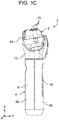
- Fig. 1C is a side view illustrating electric shaver 2 according to the exemplary embodiment.
- Fig. ID is a rear view illustrating electric shaver 2 according to the exemplary embodiment.
- a left-right direction of electric shaver 2 is defined as an X-axis direction
- a front-rear direction of electric shaver 2 is defined as a Y-axis direction
- an up-down direction of electric shaver 2 is defined as a Z-axis direction.
- Electric shaver 2 is an electric shaver having both a shaving function for shaving body hair (beard) grown on a skin surface of a human body and a skin care function for caring for the skin surface of the human body. As shown in Figs. 1A to ID, electric shaver 2 includes shaver main body 4 and blade head 6.
- Shaver main body 4 includes grip part 8 and coupling part 10.
- Grip part 8 is formed in a substantially bottomed cylindrical shape, and is formed in an elongated shape in the up-down direction (Z-axis direction).
- Grip part 8 is made, for example, of resin.
- a user grips grip part 8 by hand.
- a secondary battery (not shown) for supplying electric power to each electronic component or the like is disposed inside grip part 8.
- power switch 12 is a switch for switching on and off of a power source of electric shaver 2.
- Changeover switch 14 is a switch for switching a weak current supplied from electrode 30, which will described later, to the skin surface in, for example, three stages ("strong”, “weak”, and “off”).
- Temperature selector switch 16 is a switch for switching the temperature of electrode 30 in, for example, three stages ("high”, "low”, and “off”).
- counter electrode part 18 made of, for example, metal, is disposed on back surface 8b of grip part 8.
- Counter electrode part 18 is formed in an elongated shape in a longitudinal direction (Z-axis direction) of grip part 8.
- Counter electrode part 18 preferably has arrangement, a shape, and a size such that a palm or a finger of a user reliably touches counter electrode part 18 when the user holds grip part 8 with hand.
- a material of counter electrode part 18 is not limited to metal, and may be, for example, a conductive resin or an insulating resin coated with metal plating.
- Coupling part 10 is disposed at one end portion of grip part 8 in the longitudinal direction. Coupling part 10 couples blade head 6 to grip part 8 so as to be swingable in the front-rear direction (Y-axis direction), the left-right direction (X-axis direction), or both the directions.
- Blade head 6 has blade surface 20 for shaving body hair grown on a skin surface in a state of being in contact with the skin surface. Blade head 6 swings in the front-rear direction, the left-right direction, or both the direction with respect to shaver main body 4. As a result, when the user holds grip part 8 by hand and moves blade surface 20 of blade head 6 on the skin surface while pressing the blade surface against the skin surface, blade surface 20 comes into close contact with the skin surface while following a shape of the skin surface.
- Fig. 2 is a perspective view illustrating blade head 6 according to the exemplary embodiment.
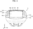
- Fig. 3 is a front view illustrating blade head 6 according to the exemplary embodiment.
- Fig. 4 is a top view illustrating blade head 6 according to the exemplary embodiment.
- Fig. 5 is a side view illustrating blade head 6 according to the exemplary embodiment.
- Fig. 6 is a cross-sectional view of a main part of blade head 6 according to the exemplary embodiment taken along line VI-VI in Fig. 4 .
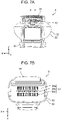
- Fig. 7A is a rear view illustrating blade head 6 according to the exemplary embodiment in a state where outer blade cassette 34 has been removed.
- Fig. 1 is a perspective view illustrating blade head 6 according to the exemplary embodiment.
- Fig. 3 is a front view illustrating blade head 6 according to the exemplary embodiment.
- Fig. 4 is a top view illustrating blade head 6 according to the exemplary embodiment.
- Fig. 5 is a side view illustrating blade head 6 according
- FIG. 7B is a top view illustrating blade head 6 according to the exemplary embodiment in a state where outer blade cassette 34 has been removed.
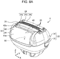
- Fig. 8A is a diagram for explaining arrangement of first temperature sensor 48 and second temperature sensor 50 in blade head 6 according to the exemplary embodiment.
- Fig. 8B is a perspective view illustrating first temperature sensor 48 according to the exemplary embodiment.
- blade head 6 has blade frame 22, outer blade 24, roller 26, inner blade 28, and electrode 30.
- Blade frame 22 has frame body 32 and outer blade cassette 34.
- Frame body 32 is coupled to one end portion in the longitudinal direction of grip part 8 via coupling part 10 so as to be swingable in the front-rear direction, or the left-right direction, or both the directions.
- Outer blade cassette 34 is detachably attached to frame body 32.
- Outer blade 24 is supported by outer blade cassette 34.
- Outer blade 24 has three outer blades, i.e., first net outer blade 24a, slit blade 24b, and second net outer blade 24c.
- First net outer blade 24a, slit blade 24b, and second net outer blade 24c are disposed in this order in the front-rear direction.
- First net outer blade 24a, slit blade 24b, and second net outer blade 24c define blade surface 20 described above.
- Each of first net outer blade 24a, slit blade 24b, and second net outer blade 24c may be made of metal such as stainless steel, or of resin, for example.
- outer blade 24 has three outer blades, the present disclosure is not limited thereto, and outer blade 24 may have any number of outer blades.
- first net outer blade 24a and second net outer blade 24c are each formed in an elongated shape in the left-right direction (X-axis direction) (an example of a predetermined direction), and are disposed substantially parallel to each other.
- first net outer blade 24a and second net outer blade 24c are each formed in a curved shape curved in the longitudinal direction (X-axis direction) so as to protrude upward (toward a plus side of the Z-axis).
- first net outer blade 24a and second net outer blade 24c are each formed to be curved in an inverted U shape in a lateral direction (Y-axis direction) so as to protrude upward.
- a plurality of blade holes are formed each in first net outer blade 24a and second net outer blade 24c.
- slit blade 24b is formed in an elongated shape in the left-right direction, and is disposed substantially parallel to each of first net outer blade 24a and second net outer blade 24c.
- slit blade 24b is formed in a substantially inverted U-shape in the lateral direction (Y-axis direction).
- an upper surface (surface defining blade surface 20) of slit blade 24b is formed with a flat surface.
- a plurality of slit-shaped blade holes 36 are formed in slit blade 24b.
- roller 26 is rotatably supported by outer blade cassette 34.
- Roller 26 is formed in an elongated shape in the left-right direction, and is disposed between first net outer blade 24a and first electrode part 42, which will be described later, of electrode 30.
- roller 26 projects more toward a skin surface side (the plus side of the Z-axis) than blade surface 20 of outer blade 24 and first electrode surface 42a, which will be described later, of first electrode part 42.
- roller 26 projects more toward the skin surface than plane 38 (indicated by a chain line in Fig. 6 ) including blade surface 20 and first electrode surface 42a.
- inner blade 28 is supported by frame body 32 via inner blade driver 40, and is disposed between outer blade 24 and frame body 32.
- inner blade 28 has three inner blades, i.e., first inner blade 28a, slit inner blade 28b, and second inner blade 28c.
- First inner blade 28a, slit inner blade 28b, and second inner blade 28c are disposed so as to be opposed to first net outer blade 24a, slit blade 24b, and second net outer blade 24c, respectively.
- first inner blade 28a, slit inner blade 28b, and second inner blade 28c reciprocate linearly with a predetermined amplitude in the left-right direction with respect to first net outer blade 24a, slit blade 24b, and second net outer blade 24c, respectively.
- body hair inserted into blade holes of first net outer blade 24a and second net outer blade 24c and blade holes 36 of slit blade 24b is pinched and cut by cooperation of first net outer blade 24a, slit blade 24b, and second net outer blade 24c, and first inner blade 28a, slit inner blade 28b, and second inner blade 28c.
- Electrode 30 is for performing skin surface care by supplying a weak current to a skin surface in a state of being in contact with the skin surface.
- electrode 30 is made of metal, for example, and is supported by outer blade cassette 34.
- the electrode 30 has first electrode part 42 and second electrode part 44, and is formed in a substantially inverted J-shaped plate as a whole in YZ cross-sectional view.
- a material of electrode 30 is not limited to metal, and may be, for example, a conductive resin or an insulating resin coated with metal plating.
- first electrode part 42 is disposed on a top surface (surface on which blade surface 20 is disposed) of blade head 6.
- First electrode surface 42a is formed on a periphery of first electrode part 42.
- First electrode surface 42a is disposed side by side with blade surface 20 in the front-rear direction (direction substantially perpendicular to the left-right direction).
- first electrode surface 42a is formed in a curved shape curved in the left-right direction so as to protrude upward.
- a curvature of the curved shape of first electrode surface 42a is the same (including substantially the same) as a curvature of each curved shape of first net outer blade 24a and second net outer blade 24c.
- second electrode part 44 is disposed on a front of blade head 6 (a surface hanging down toward front surface 8a of grip part 8 from the top surface of blade head 6).
- Second electrode surface 44a is formed on a periphery of second electrode part 44.
- Second electrode surface 44a continuously extends from first electrode surface 42a. Specifically, second electrode surface 44a hangs down from first electrode surface 42a in a direction (a minus side of the Z-axis) intersecting first electrode surface 42a.
- Second electrode surface 44a has an area larger than that of first electrode surface 42a.
- second electrode surface 44a is formed in a curved shape curved in the left-right direction so as to protrude forward (a minus side of the Y-axis) when blade surface 20 is viewed in an XY plane. This enables second electrode surface 44a to be efficiently fitted to a recessed surface of a face, for example, when second electrode surface 44a is brought into contact with the skin surface in a second mode, which will be described later.
- boundary part 46 between first electrode surface 42a and second electrode surface 44a is formed in a curved shape.
- first temperature sensor 48 and second temperature sensor 50 are embedded in first electrode surface 42a and second electrode surface 44a, respectively.
- First temperature sensor 48 detects temperature of the skin surface in contact with first electrode surface 42a.
- Second temperature sensor 50 detects temperature of the skin surface in contact with second electrode surface 44a.
- first temperature sensor 48 has temperature detection block 52 and heat insulating sheet 54.
- Temperature detection block 52 detects the temperature of the skin surface in contact with first electrode surface 42a, and outputs temperature data indicating the detected temperature to controller 62, which will be described later.
- Heat insulating sheet 54 is disposed so as to cover a surface of temperature detection block 52, and blocks heat transfer from first electrode part 42 to temperature detection block 52. Since a configuration of second temperature sensor 50 is the same as the configuration of first temperature sensor 48, description thereof will be omitted.
- FIG. 9 is a block diagram illustrating the functional configuration of electric shaver 2 according to the exemplary embodiment.
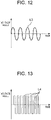
- Figs. 10 to 13 is a diagram showing an example of an application pattern of a voltage applied to electrode 30 of electric shaver 2 according to the exemplary embodiment.
- electric shaver 2 includes, as a functional configuration, first temperature sensor 48, second temperature sensor 50, drive unit 56, voltage supply unit 58, heater 60, and controller 62.
- First temperature sensor 48 detects temperature of a skin surface in contact with first electrode surface 42a, and outputs temperature data indicating the detected temperature to controller 62.
- Second temperature sensor 50 detects temperature of a skin surface in contact with second electrode surface 44a, and outputs temperature data indicating the detected temperature to controller 62.
- Drive unit 56 is a motor for driving inner blade driver 40. Although not shown in Figs. 1A to ID, drive unit 56 is disposed, for example, inside shaver main body 4.
- Voltage supply unit 58 is a voltage supply source for applying a predetermined voltage to electrode 30. Although not shown in Figs. 1A to ID, voltage supply unit 58 is disposed inside shaver main body 4, for example. When voltage supply unit 58 applies a predetermined voltage to electrode 30, a weak current of, for example, about several ⁇ A is supplied to the skin surface which has been in contact with electrode 30. Note that a biological current of 100 ⁇ A to 200 ⁇ A flows through a human body, and it has been demonstrated that natural healing power is enhanced by causing a weak current close to the biological current to flow through the human body from the outside of the body.
- the voltage supply unit 58 can apply, as the predetermined voltage to be applied to electrode 30, a) a DC voltage of constant voltage value L1 as shown in Fig. 10 , b) a DC voltage of rectangular wave L2 as shown in Fig. 11 , c) an AC voltage of sinusoidal wave L3 as shown in Fig. 12 , or d) an AC voltage of rectangular wave L4 as shown in Fig. 13 , or the like.
- voltage supply unit 58 may apply an AC voltage of a triangular wave as the predetermined voltage to be applied to electrode 30. In the example shown in Fig.
- voltage supply unit 58 preferably applies a DC voltage having constant voltage value VI within a range from 0.01 V to 20 V to electrode 30 in order to activate skin tissue of the skin surface.
- constant voltage value L1 is lower than 0.01 V, the skin surface cannot be maintained in a normal potential state.
- constant voltage value L1 exceeds 20 V, an excessive current may flow through the skin surface to decrease number of cells on the skin surface by electrolysis.
- the predetermined voltage applied by voltage supply unit 58 may be any kind of voltage such as a constant voltage, a pulse voltage, or a voltage having a value that periodically varies.
- the predetermined voltage is a DC voltage that has a voltage value varying such as a pulse voltage (60 Hz to 1 MHz)
- an average voltage value or a peak voltage value is preferably within the above range from 0.01 V to 20 V.
- the average voltage value of the predetermined voltage is preferably within the range from 0.01 V to 20 V.
- the peak voltage value of the predetermined voltage is preferably within the above range from 0.01 V to 20 V.
- the predetermined voltage is an AC voltage
- a weak current can be supplied to the skin surface even if the voltage value is relatively low, and electrical pain given to a user can be decreased by increasing a frequency even if the voltage value is relatively high.
- Heater 60 is a heat source for heating electrode 30. Although not illustrated in Figs. 1A to ID, heater 60 is disposed inside blade head 6, for example.
- Controller 62 controls drive unit 56 on the basis of operation of power switch 12 by the user. Specifically, when the user operates power switch 12 to turn on electric shaver 2, controller 62 controls drive unit 56 to drive inner blade driver 40. When the user operates power switch 12 to turn off electric shaver 2, controller 62 controls drive unit 56 to stop driving of inner blade driver 40.
- controller 62 may control drive unit 56 on the basis of a detection result of first temperature sensor 48 or second temperature sensor 50. Specifically, when the temperature of the skin surface detected by first temperature sensor 48 or second temperature sensor 50 is more than or equal to a threshold value, controller 62 determines that inflammation has occurred on the skin surface, and controls drive unit 56 to decrease the amplitude of inner blade 28. Accordingly, it is possible to suppress putting of a burden on the skin surface during shaving. On the other hand, when the temperature of the skin surface detected by first temperature sensor 48 or second temperature sensor 50 is less than the threshold, controller 62 determines that the state of the skin surface is good, and controls drive unit 56 to increase the amplitude of inner blade 28. This enables deep shaving of body hair during shaving.
- controller 62 controls voltage supply unit 58 on the basis of the operation of changeover switch 14 by the user. Specifically, when the user operates changeover switch 14 to switch the weak current which is supplied from electrode 30 to the skin surface to "strong", controller 62 controls voltage supply unit 58 so that the weak current which is supplied from electrode 30 to the skin surface has a first current value. In a case where the user operates changeover switch 14 to switch the weak current which is supplied from electrode 30 to the skin surface to "weak”, controller 62 controls voltage supply unit 58 so that the weak current which is supplied from electrode 30 to the skin surface has a second current value smaller than the first current value. In a case where the user operates the changeover switch 14 to switch the weak current which is supplied from electrode 30 to the skin surface to "off”, controller 62 controls voltage supply unit 58 such that the supply of the weak current from electrode 30 to the skin surface is stopped.
- controller 62 controls drive unit 56 and voltage supply unit 58 to switch from one of the first mode and the second mode to the other. In the first mode, shaving and skin surface care are simultaneously performed. In the second mode, only skin surface care is performed. In the first mode, controller 62 controls drive unit 56 to drive inner blade driver 40, and controls voltage supply unit 58 to supply a weak current from electrode 30 to the skin surface. In the second mode, controller 62 controls drive unit 56 to stop driving of inner blade driver 40, and controls voltage supply unit 58 to supply a weak current from electrode 30 to the skin surface.
- controller 62 controls energization of heater 60 on the basis of user's operation of temperature selector switch 16. Specifically, when the user operates temperature selector switch 16 to switch the temperature of electrode 30 to "high”, controller 62 controls energization of heater 60 such that the temperature of electrode 30 becomes a first temperature. When the user operates temperature selector switch 16 to switch the temperature of electrode 30 to "low”, controller 62 controls energization of heater 60 such that the temperature of electrode 30 becomes a second temperature which is lower than the first temperature. When the user operates temperature selector switch 16 to switch the temperature of electrode 30 to "off”, controller 62 stops energization of heater 60 so that electrode 30 is not heated by heater 60.
- Controller 62 may control energization of heater 60 on the basis of a detection result of first temperature sensor 48 or second temperature sensor 50. Specifically, controller 62 may control the energization of heater 60 such that the temperature of electrode 30 becomes higher (or lower) than the temperature of the skin surface. As just described, adjustment of the temperature of electrode 30 depending on the temperature of the skin surface by controller 62 enables a user to bring electrode 30 into contact with the skin surface at a comfortable temperature during shaving or care for the skin surface. In addition, an appropriate temperature difference between the skin surface and electrode 30 can be maintained, and care for the skin surface can be performed at an appropriate temperature regardless of timing, place, or the like of using electric shaver 2.
- controller 62 may control heater 60 so as to make the temperature of electrode 30 different between the first mode and the second mode. Specifically, for example, controller 62 may control heater 60 so that the temperature of electrode 30 in the first mode becomes higher than the temperature of electrode 30 in the second mode. This enables the user to bring electrode 30 into contact with the skin surface at a comfortable temperature in both the first mode and the second mode even when a proper temperature of electrode 30 differs in each of the first mode and the second mode.
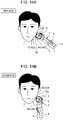
- Fig. 14A is a view for explaining a method of using electric shaver 2 according to the exemplary embodiment in the first mode.
- controller 62 switches the mode to the first mode in which shaving and skin surface care are simultaneously performed.
- the user holds grip part 8 by hand to bring blade surface 20 of blade head 6 and first electrode surface 42a of first electrode part 42 of electrode 30 into contact with the skin surface at the same time.
- the shaving for shaving body hair on the skin surface in contact with blade surface 20 is performed, and at the same time, the care is performed for the skin surface by supplying a weak current of, for example, about several ⁇ A from first electrode part 42 to the skin surface.
- roller 26 When the user holds grip part 8 by hand and presses blade head 6 against the skin surface, roller 26 most largely receives the force to press blade head 6 against the skin surface. In this way, rotating roller 26 decreases frictional resistance. Therefore, it is possible to smoothly move blade surface 20 and first electrode surface 42a on the skin surface so as to slide with less friction while firmly pressing them against the skin surface. As a result, it is possible to simultaneously perform shaving and skin surface care while suppressing a burden on the skin surface.
- a minus potential can be applied to the skin surface subjected to shaving by using electrode 30 as a negative electrode and counter electrode part 18 as a positive electrode. This makes it possible to maintain the skin surface in the normal potential state, and to effectively care for the skin surface.
- Fig. 14B is a view for explaining a method of using electric shaver 2 according to the exemplary embodiment in the second mode.
- controller 62 switches the mode to the second mode in which only the skin surface care is performed.
- the user holds grip part 8 by hand and brings second electrode surface 44a of second electrode part 44 of electrode 30 into contact with the skin surface.
- blade surface 20 is not in contact with the skin surface.
- shaving is not performed, and only care is performed for the skin surface to which a weak current of, for example, about several ⁇ A is supplied from second electrode part 44 to the skin surface. Since controller 62 stops driving of inner blade driver 40, wasteful consumption of the secondary battery built in electric shaver 2 can be suppressed.
- electric shaver 2 includes: outer blade 24 that comes into contact with a skin surface; inner blade 28 that linearly reciprocates with respect to outer blade 24 to cut body hair on the skin surface in cooperation with the outer blade 24; and electrode 30 that comes into contact with the skin surface to supply a weak current to the skin surface.
- Electrode 30 includes first electrode part 42 in which first electrode surface 42a disposed side by side with outer blade 24 is formed, and second electrode part 44 in which second electrode surface 44a hanging down from first electrode surface 42a in a direction intersecting first electrode surface 42a is formed.
- the user when, for example, a user wants to simultaneously perform shaving and skin surface care, the user brings outer blade 24 and first electrode surface 42a into contact with the skin surface simultaneously. Furthermore, in a case, for example, where the user wants to perform only skin surface care, the user brings only second electrode surface 44a into contact with the skin surface without bringing outer blade 24 into contact with the skin surface. Accordingly, in a case where the user wants to perform only skin surface care, it is possible to effectively care for the skin surface while suppressing damage to the skin surface by outer blade 24.
- boundary part 46 between first electrode surface 42a and second electrode surface 44a is formed in a curved shape.
- first electrode surface 42a or second electrode surface 44a with respect to the skin surface can be secured.
- outer blade 24 is formed in an elongated shape in a predetermined direction, and is formed in a curved shape in the predetermined direction.
- First electrode surface 42a is disposed side by side with outer blade 24 in a direction perpendicular (including substantially perpendicular) to the predetermined direction, and is formed in the predetermined direction in a curved shape having a curvature identical (including substantially identical) to that of the curved shape of outer blade 24.
- outer blade 24 and first electrode surface 42a when outer blade 24 and first electrode surface 42a are simultaneously brought into contact with the skin surface, outer blade 24 and first electrode surface 42a can be pressed against the skin surface with substantially the same pressure. As a result, it is possible to prevent only outer blade 24 from being strongly pressed against the skin surface, so that the skin surface can be gently cared. Furthermore, since it is possible to prevent only first electrode surface 42a from being strongly pressed against the skin surface, outer blade 24 can be firmly brought into close contact with the skin surface, and shaving can be effectively performed.
- second electrode surface 44a is formed in a curved shape in plan view of outer blade 24.
- second electrode surface 44a This enables second electrode surface 44a to be efficiently fitted to a recessed surface of a face, for example, when only second electrode surface 44a is brought into contact with the skin surface.
- electric shaver 2 further includes roller 26 that is disposed between outer blade 24 and first electrode part 42 and projects more toward the skin surface than outer blade 24 and first electrode part 42.
- roller 26 when the user simultaneously presses outer blade 24 and first electrode surface 42a against the skin surface, roller 26 most largely receives the force that presses outer blade 24 and first electrode surface 42a against the skin surface. In this way, rotating roller 26 decreases frictional resistance; therefore, it is possible to smoothly move outer blade 24 and first electrode surface 42a on the skin surface so as to slide with less friction while firmly pressing them against the skin surface. As a result, it is possible to simultaneously perform shaving and skin surface care while suppressing a burden on the skin surface.
- electric shaver 2 further includes drive unit 56 that linearly reciprocates inner blade 28 with respect to outer blade 24, and controller 62 that performs control to switch from one of a first mode and a second mode to the other.
- drive unit 56 In the first mode, drive unit 56 is driven and a weak current is suppled from electrode 30 to the skin surface.
- drive unit 56 In the second mode, drive unit 56 is stopped driving and a weak current is supplied from electrode 30 to the skin surface.
- controller 62 controls the temperature of electrode 30 depending on the temperature of the skin surface.
- controller 62 performs control such that the temperature of electrode 30 differs between the first mode and the second mode.
- electric shaver 2 further includes first temperature sensor 48 (second temperature sensor 50) that detects the temperature of the skin surface in contact with electrode 30. Controller 62 controls electrode 30 or drive unit 56 on the basis of the detection result of first temperature sensor 48 (second temperature sensor 50).
- Electrode 30 or drive unit 56 This enables electrode 30 or drive unit 56 to be appropriately controlled depending on the temperature of the skin surface.
- controller 62 controls the amplitude of inner blade 28 on the basis of the detection result of first temperature sensor 48 (second temperature sensor 50).
- controller 62 controls the temperature of electrode 30 on the basis of the detection result of first temperature sensor 48 (second temperature sensor 50).
- blade head 6 is provided with outer blade 24 and electrode 30.
- Electrode 30 includes first electrode surface 42a disposed side by side with outer blade 24 and second electrode surface 44a extending from first electrode surface 42a so as to hang down to the front side of blade head 6.
- boundary part 46 between first electrode surface 42a and second electrode surface 44a is formed in a curved shape.
- first electrode surface 42a or second electrode surface 44a with respect to the skin surface can be secured.
- outer blade 24 is formed in an elongated shape in a predetermined direction, and is formed in a curved shape in the predetermined direction.
- First electrode surface 42a is disposed side by side with outer blade 24 in a direction perpendicular (including substantially perpendicular) to the predetermined direction, and is formed in the predetermined direction in a curved shape having a curvature identical (including substantially identical) to that of the curved shape of outer blade 24.
- outer blade 24 and first electrode surface 42a when outer blade 24 and first electrode surface 42a are simultaneously brought into contact with the skin surface, outer blade 24 and first electrode surface 42a can be pressed against the skin surface with substantially the same pressure. As a result, it is possible to prevent only outer blade 24 from being strongly pressed against the skin surface, so that the skin surface can be gently cared. Furthermore, since it is possible to prevent only first electrode surface 42a from being strongly pressed against the skin surface, outer blade 24 can be firmly brought into close contact with the skin surface, and shaving can be effectively performed.
- second electrode surface 44a is formed in a curved shape in plan view of outer blade 24.
- second electrode surface 44a This enables second electrode surface 44a to be efficiently fitted to a recessed surface of a face, for example, when only second electrode surface 44a is brought into contact with the skin surface.
- controller 62 includes, for example, a microcontroller having one or more processors and one or more memories.
- the microcontroller realizes a function as controller 62 by executing a program recorded in the one or more memories by the one or more processors.
- the program may be recorded in a memory in advance, may be provided being recorded in a non-transitory recording medium such as a memory card, or may be provided through an electric communication line.
- the program is a program for causing the one or more processors to function as controller 62.
- the exemplary embodiment has been described in the foregoing as an example of the technique disclosed in the present application.
- the technique according to the present disclosure is, however, not limited to the above exemplary embodiment, and is applicable to other exemplary embodiments having appropriate modifications, replacements, additions, omissions, and the like.
- a new exemplary embodiment can be made by combining the components described in the above exemplary embodiment.
- second electrode part 44 is disposed on the front of blade head 6, the present invention is not limited thereto, and second electrode part 44 may be disposed on a back surface of blade head 6 (the surface hanging down from the top surface of blade head 6 to the back surface 8b of grip part 8). In this case, second electrode surface 44a is disposed to hang down from first electrode surface 42a toward the back surface of blade head 6.
- the present disclosure is applicable to, for example, an electric shaver having both a shaving function and a skin care function.
Landscapes
- Life Sciences & Earth Sciences (AREA)
- Forests & Forestry (AREA)
- Engineering & Computer Science (AREA)
- Mechanical Engineering (AREA)
- Dry Shavers And Clippers (AREA)
Abstract
Description
- The present disclosure relates to an electric shaver.
- There is known an electric shaver having both a shaving function for shaving body hair and a skin care function for skin surface care (see, e.g., Patent Literature 1). A blade head of this type of electric shaver includes an outer blade, an inner blade linearly reciprocating with respect to the outer blade, and an electrode part for supplying a weak current to a skin surface. The outer blade includes a pair of net outer blades, and a slit blade disposed between the pair of net outer blades. The electrode part is disposed between one of the pair of net outer blades and the slit blade.
- In a state where the outer blade is in contact with the skin surface, the inner blade reciprocates linearly with respect to the outer blade, so that body hair inserted into a blade hole of the outer blade is pinched between the inner blade and the outer blade and cut. In addition, in a state where the electrode part is in contact with the skin surface, it is possible to care for a skin surface by supplying a weak current from the electrode part to the skin surface.
- PTL 1: Unexamined
Japanese Patent Publication No. 2006-343322 - However, since in the above-described conventional electric shaver, even in a case where a user wants to perform only skin surface care, the outer blade and the electrode part come into contact with the skin surface at the same time, there arises a problem that the skin surface might be damaged by the outer blade.
- The present disclosure has been made in view of such problem, and an object of the present disclosure is to provide an electric shaver capable of effectively performing skin surface care while suppressing damage to a skin surface by an outer blade.
- In order to solve the above problem, an electric shaver according to one aspect of the present disclosure includes: an outer blade that comes into contact with a skin surface; an inner blade that linearly reciprocates with respect to the outer blade to cut body hair on the skin surface in cooperation with the outer blade; and an electrode that comes into contact with the skin surface to supply a weak current to the skin surface. the electrode comprises a first electrode part in which a first electrode surface disposed side by side with the outer blade is formed; and a second electrode part in which a second electrode surface hanging down from the first electrode surface in a direction intersecting the first electrode surface is formed.
- In the electric shaver according to one aspect of the present disclosure, it is possible to effectively perform skin surface care while suppressing damage to the skin surface by the outer blade.
-
-
Fig. 1A is a perspective view illustrating an electric shaver according to an exemplary embodiment. -
Fig. 1B is a front view illustrating the electric shaver according to the exemplary embodiment. -
Fig. 1C is a side view illustrating the electric shaver according to the exemplary embodiment. -
Fig. 1D is a rear view illustrating the electric shaver according to the exemplary embodiment. -
Fig. 2 is a perspective view illustrating a blade head according to the exemplary embodiment. -
Fig. 3 is a front view illustrating the blade head according to the exemplary embodiment. -
Fig. 4 is a top view illustrating the blade head according to the exemplary embodiment. -
Fig. 5 is a side view illustrating the blade head according to the exemplary embodiment. -
Fig. 6 is a cross-sectional view of a main part of the blade head according to the exemplary embodiment taken along line VI-VI inFig. 4 . -
Fig. 7A is a rear view illustrating the blade head according to the exemplary embodiment in a state where an outer blade cassette has been removed. -
Fig. 7B is a top view illustrating the blade head according to the exemplary embodiment in a state where the outer blade cassette has been removed. -
Fig. 8A is a view for explaining arrangement of a first temperature sensor and a second temperature sensor in the blade head according to the exemplary embodiment. -
Fig. 8B is a perspective view illustrating the first temperature sensor according to the exemplary embodiment. -
Fig. 9 is a block diagram showing a functional configuration of the electric shaver according to the exemplary embodiment. -
Fig. 10 is a diagram showing an example of an application pattern of a voltage applied to an electrode of the electric shaver according to the exemplary embodiment. -
Fig. 11 is a diagram showing an example of an application pattern of a voltage applied to the electrode of the electric shaver according to the exemplary embodiment. -
Fig. 12 is a diagram showing an example of an application pattern of a voltage applied to the electrode of the electric shaver according to the exemplary embodiment. -
Fig. 13 is a diagram showing an example of an application pattern of a voltage applied to the electrode of the electric shaver according to the exemplary embodiment. -
Fig. 14A is a view for explaining a method of using the electric shaver in a first mode according to the exemplary embodiment. -
Fig. 14B is a view for explaining a method of using the electric shaver in a second mode according to the exemplary embodiment. - The exemplary embodiment will be specifically described below with reference to the drawings.
- Note that the exemplary embodiment to be described below provides comprehensive or specific examples of the present disclosure. Numerical values, shapes, materials, components, arrangement positions and connection modes of the components, steps, an order of the steps, and the like shown in the following exemplary embodiment are examples only, and are not intended to limit the present disclosure. Further, among the components in the following exemplary embodiment, those not recited in independent claims representing the most superordinate concept will be described herein as optional components.
- Each drawing is a schematic view and is not necessarily strictly illustrated. In addition, in each drawing, substantially the same configurations are denoted by the same reference marks to eliminate or simplify overlapped description.
- First, an overall structure of
electric shaver 2 according to the exemplary embodiment will be described with reference toFigs. 1A to ID.Fig. 1A is a perspective view illustratingelectric shaver 2 according to the exemplary embodiment.Fig. 1B is a front view illustratingelectric shaver 2 according to the exemplary embodiment.Fig. 1C is a side view illustratingelectric shaver 2 according to the exemplary embodiment. Fig. ID is a rear view illustratingelectric shaver 2 according to the exemplary embodiment. - In
Figs. 1A to ID, a left-right direction ofelectric shaver 2 is defined as an X-axis direction, a front-rear direction ofelectric shaver 2 is defined as a Y-axis direction, and an up-down direction ofelectric shaver 2 is defined as a Z-axis direction. -
Electric shaver 2 according to the exemplary embodiment is an electric shaver having both a shaving function for shaving body hair (beard) grown on a skin surface of a human body and a skin care function for caring for the skin surface of the human body. As shown inFigs. 1A to ID,electric shaver 2 includes shavermain body 4 andblade head 6. - Shaver
main body 4 includesgrip part 8 andcoupling part 10.Grip part 8 is formed in a substantially bottomed cylindrical shape, and is formed in an elongated shape in the up-down direction (Z-axis direction).Grip part 8 is made, for example, of resin. When usingelectric shaver 2, a user gripsgrip part 8 by hand. Note that a secondary battery (not shown) for supplying electric power to each electronic component or the like is disposed insidegrip part 8. - As illustrated in
Figs. 1A and1B ,power switch 12,changeover switch 14, andtemperature selector switch 16 are disposed onfront surface 8a ofgrip part 8.Power switch 12 is a switch for switching on and off of a power source ofelectric shaver 2.Changeover switch 14 is a switch for switching a weak current supplied fromelectrode 30, which will described later, to the skin surface in, for example, three stages ("strong", "weak", and "off").Temperature selector switch 16 is a switch for switching the temperature ofelectrode 30 in, for example, three stages ("high", "low", and "off"). - As shown in
Figs. 1C and ID,counter electrode part 18 made of, for example, metal, is disposed onback surface 8b ofgrip part 8.Counter electrode part 18 is formed in an elongated shape in a longitudinal direction (Z-axis direction) ofgrip part 8.Counter electrode part 18 preferably has arrangement, a shape, and a size such that a palm or a finger of a user reliably touchescounter electrode part 18 when the user holdsgrip part 8 with hand. A material ofcounter electrode part 18 is not limited to metal, and may be, for example, a conductive resin or an insulating resin coated with metal plating. - Coupling
part 10 is disposed at one end portion ofgrip part 8 in the longitudinal direction. Couplingpart 10couples blade head 6 to grippart 8 so as to be swingable in the front-rear direction (Y-axis direction), the left-right direction (X-axis direction), or both the directions. -
Blade head 6 hasblade surface 20 for shaving body hair grown on a skin surface in a state of being in contact with the skin surface.Blade head 6 swings in the front-rear direction, the left-right direction, or both the direction with respect to shavermain body 4. As a result, when the user holdsgrip part 8 by hand and movesblade surface 20 ofblade head 6 on the skin surface while pressing the blade surface against the skin surface,blade surface 20 comes into close contact with the skin surface while following a shape of the skin surface. - Next, structure of
blade head 6 will be described with reference toFigs. 2 to 8B .Fig. 2 is a perspective viewillustrating blade head 6 according to the exemplary embodiment.Fig. 3 is a front view illustratingblade head 6 according to the exemplary embodiment.Fig. 4 is a top view illustratingblade head 6 according to the exemplary embodiment.Fig. 5 is a side view illustratingblade head 6 according to the exemplary embodiment.Fig. 6 is a cross-sectional view of a main part ofblade head 6 according to the exemplary embodiment taken along line VI-VI inFig. 4 .Fig. 7A is a rear view illustratingblade head 6 according to the exemplary embodiment in a state whereouter blade cassette 34 has been removed.Fig. 7B is a top view illustratingblade head 6 according to the exemplary embodiment in a state whereouter blade cassette 34 has been removed.Fig. 8A is a diagram for explaining arrangement offirst temperature sensor 48 andsecond temperature sensor 50 inblade head 6 according to the exemplary embodiment.Fig. 8B is a perspective view illustratingfirst temperature sensor 48 according to the exemplary embodiment. - As illustrated in
Figs. 2 to 5 ,blade head 6 hasblade frame 22,outer blade 24,roller 26,inner blade 28, andelectrode 30. -
Blade frame 22 hasframe body 32 andouter blade cassette 34.Frame body 32 is coupled to one end portion in the longitudinal direction ofgrip part 8 viacoupling part 10 so as to be swingable in the front-rear direction, or the left-right direction, or both the directions.Outer blade cassette 34 is detachably attached to framebody 32. -
Outer blade 24 is supported byouter blade cassette 34.Outer blade 24 has three outer blades, i.e., first netouter blade 24a, slitblade 24b, and second netouter blade 24c. First netouter blade 24a, slitblade 24b, and second netouter blade 24c are disposed in this order in the front-rear direction. First netouter blade 24a, slitblade 24b, and second netouter blade 24c defineblade surface 20 described above. Each of first netouter blade 24a, slitblade 24b, and second netouter blade 24c may be made of metal such as stainless steel, or of resin, for example. Further, although in the present exemplary embodiment,outer blade 24 has three outer blades, the present disclosure is not limited thereto, andouter blade 24 may have any number of outer blades. - As shown in
Figs. 2 and4 , first netouter blade 24a and second netouter blade 24c are each formed in an elongated shape in the left-right direction (X-axis direction) (an example of a predetermined direction), and are disposed substantially parallel to each other. In XZ front view shown inFig. 3 , first netouter blade 24a and second netouter blade 24c are each formed in a curved shape curved in the longitudinal direction (X-axis direction) so as to protrude upward (toward a plus side of the Z-axis). In YZ side view shown inFig. 5 , first netouter blade 24a and second netouter blade 24c are each formed to be curved in an inverted U shape in a lateral direction (Y-axis direction) so as to protrude upward. A plurality of blade holes (not shown) are formed each in first netouter blade 24a and second netouter blade 24c. - As shown in
Figs. 2 and4 ,slit blade 24b is formed in an elongated shape in the left-right direction, and is disposed substantially parallel to each of first netouter blade 24a and second netouter blade 24c. In YZ side view shown inFig. 5 ,slit blade 24b is formed in a substantially inverted U-shape in the lateral direction (Y-axis direction). In other words, an upper surface (surface defining blade surface 20) ofslit blade 24b is formed with a flat surface. A plurality of slit-shaped blade holes 36 (seeFig. 4 ) are formed inslit blade 24b. - As shown in
Figs. 2 and4 ,roller 26 is rotatably supported byouter blade cassette 34.Roller 26 is formed in an elongated shape in the left-right direction, and is disposed between first netouter blade 24a andfirst electrode part 42, which will be described later, ofelectrode 30. As shown inFig. 6 ,roller 26 projects more toward a skin surface side (the plus side of the Z-axis) thanblade surface 20 ofouter blade 24 andfirst electrode surface 42a, which will be described later, offirst electrode part 42. In other words,roller 26 projects more toward the skin surface than plane 38 (indicated by a chain line inFig. 6 ) includingblade surface 20 andfirst electrode surface 42a. - As shown in
Fig. 7A ,inner blade 28 is supported byframe body 32 viainner blade driver 40, and is disposed betweenouter blade 24 andframe body 32. As shown inFig. 7B ,inner blade 28 has three inner blades, i.e., firstinner blade 28a, slit inner blade 28b, and second inner blade 28c. Firstinner blade 28a, slit inner blade 28b, and second inner blade 28c are disposed so as to be opposed to first netouter blade 24a, slitblade 24b, and second netouter blade 24c, respectively. - When
inner blade driver 40 is driven, firstinner blade 28a, slit inner blade 28b, and second inner blade 28c reciprocate linearly with a predetermined amplitude in the left-right direction with respect to first netouter blade 24a, slitblade 24b, and second netouter blade 24c, respectively. As a result, body hair inserted into blade holes of first netouter blade 24a and second netouter blade 24c and blade holes 36 ofslit blade 24b is pinched and cut by cooperation of first netouter blade 24a, slitblade 24b, and second netouter blade 24c, and firstinner blade 28a, slit inner blade 28b, and second inner blade 28c. -
Electrode 30 is for performing skin surface care by supplying a weak current to a skin surface in a state of being in contact with the skin surface. As shown inFigs. 2 to 5 ,electrode 30 is made of metal, for example, and is supported byouter blade cassette 34. Theelectrode 30 hasfirst electrode part 42 andsecond electrode part 44, and is formed in a substantially inverted J-shaped plate as a whole in YZ cross-sectional view. A material ofelectrode 30 is not limited to metal, and may be, for example, a conductive resin or an insulating resin coated with metal plating. - As illustrated in
Figs. 2 to 5 ,first electrode part 42 is disposed on a top surface (surface on which blade surface 20 is disposed) ofblade head 6.First electrode surface 42a is formed on a periphery offirst electrode part 42.First electrode surface 42a is disposed side by side withblade surface 20 in the front-rear direction (direction substantially perpendicular to the left-right direction). - As illustrated in
Fig. 3 ,first electrode surface 42a is formed in a curved shape curved in the left-right direction so as to protrude upward. At this time, a curvature of the curved shape offirst electrode surface 42a is the same (including substantially the same) as a curvature of each curved shape of first netouter blade 24a and second netouter blade 24c. This enablesblade surface 20 andfirst electrode surface 42a to be pressed against the skin surface with substantially the same pressure whenblade surface 20 andfirst electrode surface 42a are simultaneously brought into contact with the skin surface in a first mode, which will be described later. As a result, since it is possible to preventonly blade surface 20 from being strongly pressed against the skin surface, the skin surface can be gently cared. In addition, since it is also possible to prevent onlyfirst electrode surface 42a from being strongly pressed against the skin surface,blade surface 20 can be firmly brought into close contact with the skin surface, and shaving can be effectively performed. - As illustrated in
Figs. 2 to 5 ,second electrode part 44 is disposed on a front of blade head 6 (a surface hanging down towardfront surface 8a ofgrip part 8 from the top surface of blade head 6).Second electrode surface 44a is formed on a periphery ofsecond electrode part 44.Second electrode surface 44a continuously extends fromfirst electrode surface 42a. Specifically,second electrode surface 44a hangs down fromfirst electrode surface 42a in a direction (a minus side of the Z-axis) intersectingfirst electrode surface 42a.Second electrode surface 44a has an area larger than that offirst electrode surface 42a. - As shown in
Fig. 4 ,second electrode surface 44a is formed in a curved shape curved in the left-right direction so as to protrude forward (a minus side of the Y-axis) whenblade surface 20 is viewed in an XY plane. This enablessecond electrode surface 44a to be efficiently fitted to a recessed surface of a face, for example, whensecond electrode surface 44a is brought into contact with the skin surface in a second mode, which will be described later. - As illustrated in
Figs. 5 and 6 ,boundary part 46 betweenfirst electrode surface 42a andsecond electrode surface 44a is formed in a curved shape. As a result, whenblade surface 20 andfirst electrode surface 42a are simultaneously brought into contact with the skin surface in the first mode, which will be described later, and whensecond electrode surface 44a is brought into contact with the skin surface in the second mode, which will be described later, a large contact area offirst electrode surface 42a orsecond electrode surface 44a with the skin surface can be secured. - As illustrated in
Fig. 8A ,first temperature sensor 48 and second temperature sensor 50 (an example of a temperature sensor) are embedded infirst electrode surface 42a andsecond electrode surface 44a, respectively.First temperature sensor 48 detects temperature of the skin surface in contact withfirst electrode surface 42a.Second temperature sensor 50 detects temperature of the skin surface in contact withsecond electrode surface 44a. As illustrated in (a) and (b) ofFig. 8B ,first temperature sensor 48 hastemperature detection block 52 andheat insulating sheet 54.Temperature detection block 52 detects the temperature of the skin surface in contact withfirst electrode surface 42a, and outputs temperature data indicating the detected temperature tocontroller 62, which will be described later. Heat insulatingsheet 54 is disposed so as to cover a surface oftemperature detection block 52, and blocks heat transfer fromfirst electrode part 42 totemperature detection block 52. Since a configuration ofsecond temperature sensor 50 is the same as the configuration offirst temperature sensor 48, description thereof will be omitted. - Next, with reference to
Figs. 9 to 13 , a functional configuration ofelectric shaver 2 according to the exemplary embodiment will be described.Fig. 9 is a block diagram illustrating the functional configuration ofelectric shaver 2 according to the exemplary embodiment. Each ofFigs. 10 to 13 is a diagram showing an example of an application pattern of a voltage applied toelectrode 30 ofelectric shaver 2 according to the exemplary embodiment. - As shown in
Fig. 9 ,electric shaver 2 includes, as a functional configuration,first temperature sensor 48,second temperature sensor 50,drive unit 56,voltage supply unit 58,heater 60, andcontroller 62. -
First temperature sensor 48 detects temperature of a skin surface in contact withfirst electrode surface 42a, and outputs temperature data indicating the detected temperature tocontroller 62.Second temperature sensor 50 detects temperature of a skin surface in contact withsecond electrode surface 44a, and outputs temperature data indicating the detected temperature tocontroller 62. -
Drive unit 56 is a motor for drivinginner blade driver 40. Although not shown inFigs. 1A to ID,drive unit 56 is disposed, for example, inside shavermain body 4. -
Voltage supply unit 58 is a voltage supply source for applying a predetermined voltage toelectrode 30. Although not shown inFigs. 1A to ID,voltage supply unit 58 is disposed inside shavermain body 4, for example. Whenvoltage supply unit 58 applies a predetermined voltage toelectrode 30, a weak current of, for example, about several µA is supplied to the skin surface which has been in contact withelectrode 30. Note that a biological current of 100 µA to 200 µA flows through a human body, and it has been demonstrated that natural healing power is enhanced by causing a weak current close to the biological current to flow through the human body from the outside of the body. - The
voltage supply unit 58 can apply, as the predetermined voltage to be applied toelectrode 30, a) a DC voltage of constant voltage value L1 as shown inFig. 10 , b) a DC voltage of rectangular wave L2 as shown inFig. 11 , c) an AC voltage of sinusoidal wave L3 as shown inFig. 12 , or d) an AC voltage of rectangular wave L4 as shown inFig. 13 , or the like. Although not illustrated,voltage supply unit 58 may apply an AC voltage of a triangular wave as the predetermined voltage to be applied toelectrode 30. In the example shown inFig. 10 ,voltage supply unit 58 preferably applies a DC voltage having constant voltage value VI within a range from 0.01 V to 20 V toelectrode 30 in order to activate skin tissue of the skin surface. When constant voltage value L1 is lower than 0.01 V, the skin surface cannot be maintained in a normal potential state. On the other hand, when constant voltage value L1 exceeds 20 V, an excessive current may flow through the skin surface to decrease number of cells on the skin surface by electrolysis. - The predetermined voltage applied by
voltage supply unit 58 may be any kind of voltage such as a constant voltage, a pulse voltage, or a voltage having a value that periodically varies. For example, in a case where the predetermined voltage is a DC voltage that has a voltage value varying such as a pulse voltage (60 Hz to 1 MHz), an average voltage value or a peak voltage value is preferably within the above range from 0.01 V to 20 V. When constant current control is performed, the average voltage value of the predetermined voltage is preferably within the range from 0.01 V to 20 V. On the other hand, when the predetermined voltage is an AC voltage, the peak voltage value of the predetermined voltage is preferably within the above range from 0.01 V to 20 V. Here, in a case where the predetermined voltage is an AC voltage, a weak current can be supplied to the skin surface even if the voltage value is relatively low, and electrical pain given to a user can be decreased by increasing a frequency even if the voltage value is relatively high. - Although in the present exemplary embodiment, the description has been made of the case where
voltage supply unit 58 performs constant voltage control, the present disclosure is not limited thereto, and the constant current control may be performed. Since in this case, the voltage value varies depending on conditions and the like, the average voltage value or the peak voltage value is preferably within the range from 0.01 V to 20 V also in this case. -
Heater 60 is a heat source forheating electrode 30. Although not illustrated inFigs. 1A to ID,heater 60 is disposed insideblade head 6, for example. -
Controller 62 controls driveunit 56 on the basis of operation ofpower switch 12 by the user. Specifically, when the user operatespower switch 12 to turn onelectric shaver 2,controller 62 controls driveunit 56 to driveinner blade driver 40. When the user operatespower switch 12 to turn offelectric shaver 2,controller 62 controls driveunit 56 to stop driving ofinner blade driver 40. - Note that
controller 62 may controldrive unit 56 on the basis of a detection result offirst temperature sensor 48 orsecond temperature sensor 50. Specifically, when the temperature of the skin surface detected byfirst temperature sensor 48 orsecond temperature sensor 50 is more than or equal to a threshold value,controller 62 determines that inflammation has occurred on the skin surface, and controls driveunit 56 to decrease the amplitude ofinner blade 28. Accordingly, it is possible to suppress putting of a burden on the skin surface during shaving. On the other hand, when the temperature of the skin surface detected byfirst temperature sensor 48 orsecond temperature sensor 50 is less than the threshold,controller 62 determines that the state of the skin surface is good, and controls driveunit 56 to increase the amplitude ofinner blade 28. This enables deep shaving of body hair during shaving. - In addition,
controller 62 controlsvoltage supply unit 58 on the basis of the operation ofchangeover switch 14 by the user. Specifically, when the user operateschangeover switch 14 to switch the weak current which is supplied fromelectrode 30 to the skin surface to "strong",controller 62 controlsvoltage supply unit 58 so that the weak current which is supplied fromelectrode 30 to the skin surface has a first current value. In a case where the user operateschangeover switch 14 to switch the weak current which is supplied fromelectrode 30 to the skin surface to "weak",controller 62 controlsvoltage supply unit 58 so that the weak current which is supplied fromelectrode 30 to the skin surface has a second current value smaller than the first current value. In a case where the user operates thechangeover switch 14 to switch the weak current which is supplied fromelectrode 30 to the skin surface to "off",controller 62 controlsvoltage supply unit 58 such that the supply of the weak current fromelectrode 30 to the skin surface is stopped. - Furthermore,
controller 62 controls driveunit 56 andvoltage supply unit 58 to switch from one of the first mode and the second mode to the other. In the first mode, shaving and skin surface care are simultaneously performed. In the second mode, only skin surface care is performed. In the first mode,controller 62 controls driveunit 56 to driveinner blade driver 40, and controlsvoltage supply unit 58 to supply a weak current fromelectrode 30 to the skin surface. In the second mode,controller 62 controls driveunit 56 to stop driving ofinner blade driver 40, and controlsvoltage supply unit 58 to supply a weak current fromelectrode 30 to the skin surface. - Furthermore,
controller 62 controls energization ofheater 60 on the basis of user's operation oftemperature selector switch 16. Specifically, when the user operatestemperature selector switch 16 to switch the temperature ofelectrode 30 to "high",controller 62 controls energization ofheater 60 such that the temperature ofelectrode 30 becomes a first temperature. When the user operatestemperature selector switch 16 to switch the temperature ofelectrode 30 to "low",controller 62 controls energization ofheater 60 such that the temperature ofelectrode 30 becomes a second temperature which is lower than the first temperature. When the user operatestemperature selector switch 16 to switch the temperature ofelectrode 30 to "off",controller 62 stops energization ofheater 60 so thatelectrode 30 is not heated byheater 60. -
Controller 62 may control energization ofheater 60 on the basis of a detection result offirst temperature sensor 48 orsecond temperature sensor 50. Specifically,controller 62 may control the energization ofheater 60 such that the temperature ofelectrode 30 becomes higher (or lower) than the temperature of the skin surface. As just described, adjustment of the temperature ofelectrode 30 depending on the temperature of the skin surface bycontroller 62 enables a user to bringelectrode 30 into contact with the skin surface at a comfortable temperature during shaving or care for the skin surface. In addition, an appropriate temperature difference between the skin surface andelectrode 30 can be maintained, and care for the skin surface can be performed at an appropriate temperature regardless of timing, place, or the like of usingelectric shaver 2. - Furthermore,
controller 62 may controlheater 60 so as to make the temperature ofelectrode 30 different between the first mode and the second mode. Specifically, for example,controller 62 may controlheater 60 so that the temperature ofelectrode 30 in the first mode becomes higher than the temperature ofelectrode 30 in the second mode. This enables the user to bringelectrode 30 into contact with the skin surface at a comfortable temperature in both the first mode and the second mode even when a proper temperature ofelectrode 30 differs in each of the first mode and the second mode. - Next, a method of using
electric shaver 2 according to the exemplary embodiment will be described with reference toFig. 14A. Fig. 14A is a view for explaining a method of usingelectric shaver 2 according to the exemplary embodiment in the first mode. - When the user operates
power switch 12 to turn onelectric shaver 2,controller 62 switches the mode to the first mode in which shaving and skin surface care are simultaneously performed. - As illustrated in
Fig. 14A , the user holdsgrip part 8 by hand to bringblade surface 20 ofblade head 6 andfirst electrode surface 42a offirst electrode part 42 ofelectrode 30 into contact with the skin surface at the same time. As a result, the shaving for shaving body hair on the skin surface in contact withblade surface 20 is performed, and at the same time, the care is performed for the skin surface by supplying a weak current of, for example, about several µA fromfirst electrode part 42 to the skin surface. - When the user holds
grip part 8 by hand and pressesblade head 6 against the skin surface,roller 26 most largely receives the force to pressblade head 6 against the skin surface. In this way, rotatingroller 26 decreases frictional resistance. Therefore, it is possible to smoothly moveblade surface 20 andfirst electrode surface 42a on the skin surface so as to slide with less friction while firmly pressing them against the skin surface. As a result, it is possible to simultaneously perform shaving and skin surface care while suppressing a burden on the skin surface. - As described above, by simultaneously performing shaving and skin surface care, particularly when skin is rough and dry, wounded skin tissue is repaired by the weak current, resulting in enabling restoration and acceleration of a barrier function of skin cornea. As a result, the skin surface after shaving can be made moist and smooth, and the state of the skin surface can be improved. In addition, since the weak current is supplied to the skin surface, the electrical stimulation given to the user is also weak, and no electrical pain is given to the user. Furthermore, since
electrode 30 is not in electrical contact withouter blade 24 ofblade head 6, even in a case whereouter blade 24 is made of metal,outer blade 24 is not electrically oxidized and corroded. In particular, it is possible to avoid occurrence of blade spill due to electric corrosion of a pointed portion ofblade surface 20 made of metal. - When the user holds
grip part 8 by hand, the user's palm or finger comes into contact withcounter electrode part 18 disposed ingrip part 8. Accordingly, whenfirst electrode surface 42a is brought into contact with the skin surface subjected to shaving, a closed circuit is formed betweenelectrode 30 andcounter electrode part 18 via a user's body. As a result, a weak current easily flows through the user's body, and a voltage having the same potential is always applied to the skin surface subjected to shaving. In addition, the user's palm or finger comes into contact withcounter electrode part 18 just by the user's holding ofgrip part 8 by hand, so thatgrip part 8 which is held by the user can be used to enhance a weak electrical stimulation effect. - Furthermore, when a DC voltage is applied to
electrode 30, a minus potential can be applied to the skin surface subjected to shaving by usingelectrode 30 as a negative electrode andcounter electrode part 18 as a positive electrode. This makes it possible to maintain the skin surface in the normal potential state, and to effectively care for the skin surface. - Next, a method of using
electric shaver 2 according to the exemplary embodiment will be described with reference toFig. 14B. Fig. 14B is a view for explaining a method of usingelectric shaver 2 according to the exemplary embodiment in the second mode. - The user operates
changeover switch 14 to switch the weak current which is supplied fromelectrode 30 to the skin surface to "strong" or "weak". As a result,controller 62 switches the mode to the second mode in which only the skin surface care is performed. - As shown in
Fig. 14B , the user holdsgrip part 8 by hand and bringssecond electrode surface 44a ofsecond electrode part 44 ofelectrode 30 into contact with the skin surface. At this time,blade surface 20 is not in contact with the skin surface. As a result, shaving is not performed, and only care is performed for the skin surface to which a weak current of, for example, about several µA is supplied fromsecond electrode part 44 to the skin surface. Sincecontroller 62 stops driving ofinner blade driver 40, wasteful consumption of the secondary battery built inelectric shaver 2 can be suppressed. - As described above, in the present exemplary embodiment,
electric shaver 2 includes:outer blade 24 that comes into contact with a skin surface;inner blade 28 that linearly reciprocates with respect toouter blade 24 to cut body hair on the skin surface in cooperation with theouter blade 24; andelectrode 30 that comes into contact with the skin surface to supply a weak current to the skin surface.Electrode 30 includesfirst electrode part 42 in whichfirst electrode surface 42a disposed side by side withouter blade 24 is formed, andsecond electrode part 44 in whichsecond electrode surface 44a hanging down fromfirst electrode surface 42a in a direction intersectingfirst electrode surface 42a is formed. - In the above electric shaver, when, for example, a user wants to simultaneously perform shaving and skin surface care, the user brings
outer blade 24 andfirst electrode surface 42a into contact with the skin surface simultaneously. Furthermore, in a case, for example, where the user wants to perform only skin surface care, the user brings onlysecond electrode surface 44a into contact with the skin surface without bringingouter blade 24 into contact with the skin surface. Accordingly, in a case where the user wants to perform only skin surface care, it is possible to effectively care for the skin surface while suppressing damage to the skin surface byouter blade 24. - In addition, in the present exemplary embodiment,
boundary part 46 betweenfirst electrode surface 42a andsecond electrode surface 44a is formed in a curved shape. - In the above case, for example, when
outer blade 24 andfirst electrode surface 42a are simultaneously brought into contact with the skin surface, or when onlysecond electrode surface 44a is brought into contact with the skin surface, a large contact area offirst electrode surface 42a orsecond electrode surface 44a with respect to the skin surface can be secured. - Furthermore, in the present exemplary embodiment,
outer blade 24 is formed in an elongated shape in a predetermined direction, and is formed in a curved shape in the predetermined direction.First electrode surface 42a is disposed side by side withouter blade 24 in a direction perpendicular (including substantially perpendicular) to the predetermined direction, and is formed in the predetermined direction in a curved shape having a curvature identical (including substantially identical) to that of the curved shape ofouter blade 24. - In the above case, for example, when
outer blade 24 andfirst electrode surface 42a are simultaneously brought into contact with the skin surface,outer blade 24 andfirst electrode surface 42a can be pressed against the skin surface with substantially the same pressure. As a result, it is possible to prevent onlyouter blade 24 from being strongly pressed against the skin surface, so that the skin surface can be gently cared. Furthermore, since it is possible to prevent onlyfirst electrode surface 42a from being strongly pressed against the skin surface,outer blade 24 can be firmly brought into close contact with the skin surface, and shaving can be effectively performed. - In the present exemplary embodiment,
second electrode surface 44a is formed in a curved shape in plan view ofouter blade 24. - This enables
second electrode surface 44a to be efficiently fitted to a recessed surface of a face, for example, when onlysecond electrode surface 44a is brought into contact with the skin surface. - Furthermore, in the present exemplary embodiment,
electric shaver 2 further includesroller 26 that is disposed betweenouter blade 24 andfirst electrode part 42 and projects more toward the skin surface thanouter blade 24 andfirst electrode part 42. - In the above case, when the user simultaneously presses
outer blade 24 andfirst electrode surface 42a against the skin surface,roller 26 most largely receives the force that pressesouter blade 24 andfirst electrode surface 42a against the skin surface. In this way, rotatingroller 26 decreases frictional resistance; therefore, it is possible to smoothly moveouter blade 24 andfirst electrode surface 42a on the skin surface so as to slide with less friction while firmly pressing them against the skin surface. As a result, it is possible to simultaneously perform shaving and skin surface care while suppressing a burden on the skin surface. - Furthermore, in the present exemplary embodiment,
electric shaver 2 further includesdrive unit 56 that linearly reciprocatesinner blade 28 with respect toouter blade 24, andcontroller 62 that performs control to switch from one of a first mode and a second mode to the other. In the first mode,drive unit 56 is driven and a weak current is suppled fromelectrode 30 to the skin surface. In the second mode,drive unit 56 is stopped driving and a weak current is supplied fromelectrode 30 to the skin surface. - In the above case, since the
same electrode 30 is used in the two modes,electric shaver 2 can be made compact, andelectrode 30 can be easily touched to a target place on the skin surface. - Furthermore, in the present exemplary embodiment,
controller 62 controls the temperature ofelectrode 30 depending on the temperature of the skin surface. - This enables the user to bring
electrode 30 into contact with the skin surface at a comfortable temperature during shaving or skin surface care. - Furthermore, in the present exemplary embodiment,
controller 62 performs control such that the temperature ofelectrode 30 differs between the first mode and the second mode. - This enables the user to bring
electrode 30 into contact with the skin surface at a comfortable temperature in both the first mode and the second mode even when a proper temperature ofelectrode 30 differs in each of the first mode and the second mode. - Furthermore, in the present exemplary embodiment,
electric shaver 2 further includes first temperature sensor 48 (second temperature sensor 50) that detects the temperature of the skin surface in contact withelectrode 30.Controller 62 controls electrode 30 or driveunit 56 on the basis of the detection result of first temperature sensor 48 (second temperature sensor 50). - This enables
electrode 30 or driveunit 56 to be appropriately controlled depending on the temperature of the skin surface. - Furthermore, in the present exemplary embodiment,
controller 62 controls the amplitude ofinner blade 28 on the basis of the detection result of first temperature sensor 48 (second temperature sensor 50). - This enables shaving to be appropriately performed depending on the temperature of the skin surface.
- Furthermore, in the present exemplary embodiment,
controller 62 controls the temperature ofelectrode 30 on the basis of the detection result of first temperature sensor 48 (second temperature sensor 50). - This enables skin surface care to be appropriately performed according to the temperature of the skin surface.
- Furthermore, in
electric shaver 2 according to the present exemplary embodiment,blade head 6 is provided withouter blade 24 andelectrode 30.Electrode 30 includesfirst electrode surface 42a disposed side by side withouter blade 24 andsecond electrode surface 44a extending fromfirst electrode surface 42a so as to hang down to the front side ofblade head 6. - In the above case, when, for example, a user wants to simultaneously perform shaving and skin surface care, the user brings
outer blade 24 andfirst electrode surface 42a into contact with the skin surface simultaneously. Furthermore, in a case, for example, where the user wants to perform only skin surface care, the user brings onlysecond electrode surface 44a into contact with the skin surface without bringingouter blade 24 into contact with the skin surface. In this way, in a case where the user wants to perform only skin surface care, it is possible to effectively care for the skin surface while suppressing damage to the skin surface byouter blade 24. - In addition, in the present exemplary embodiment,
boundary part 46 betweenfirst electrode surface 42a andsecond electrode surface 44a is formed in a curved shape. - In the above case, for example, when
outer blade 24 andfirst electrode surface 42a are simultaneously brought into contact with the skin surface, or when onlysecond electrode surface 44a is brought into contact with the skin surface, a large contact area offirst electrode surface 42a orsecond electrode surface 44a with respect to the skin surface can be secured. - Furthermore, in the present exemplary embodiment,
outer blade 24 is formed in an elongated shape in a predetermined direction, and is formed in a curved shape in the predetermined direction.First electrode surface 42a is disposed side by side withouter blade 24 in a direction perpendicular (including substantially perpendicular) to the predetermined direction, and is formed in the predetermined direction in a curved shape having a curvature identical (including substantially identical) to that of the curved shape ofouter blade 24. - In the above case, for example, when
outer blade 24 andfirst electrode surface 42a are simultaneously brought into contact with the skin surface,outer blade 24 andfirst electrode surface 42a can be pressed against the skin surface with substantially the same pressure. As a result, it is possible to prevent onlyouter blade 24 from being strongly pressed against the skin surface, so that the skin surface can be gently cared. Furthermore, since it is possible to prevent onlyfirst electrode surface 42a from being strongly pressed against the skin surface,outer blade 24 can be firmly brought into close contact with the skin surface, and shaving can be effectively performed. - In the present exemplary embodiment,
second electrode surface 44a is formed in a curved shape in plan view ofouter blade 24. - This enables
second electrode surface 44a to be efficiently fitted to a recessed surface of a face, for example, when onlysecond electrode surface 44a is brought into contact with the skin surface. - Furthermore,
controller 62 includes, for example, a microcontroller having one or more processors and one or more memories. The microcontroller realizes a function ascontroller 62 by executing a program recorded in the one or more memories by the one or more processors. The program may be recorded in a memory in advance, may be provided being recorded in a non-transitory recording medium such as a memory card, or may be provided through an electric communication line. In other words, the program is a program for causing the one or more processors to function ascontroller 62. - The exemplary embodiment has been described in the foregoing as an example of the technique disclosed in the present application. The technique according to the present disclosure is, however, not limited to the above exemplary embodiment, and is applicable to other exemplary embodiments having appropriate modifications, replacements, additions, omissions, and the like. In addition, a new exemplary embodiment can be made by combining the components described in the above exemplary embodiment.
- Although in the above exemplary embodiment,
second electrode part 44 is disposed on the front ofblade head 6, the present invention is not limited thereto, andsecond electrode part 44 may be disposed on a back surface of blade head 6 (the surface hanging down from the top surface ofblade head 6 to theback surface 8b of grip part 8). In this case,second electrode surface 44a is disposed to hang down fromfirst electrode surface 42a toward the back surface ofblade head 6. - The present disclosure is applicable to, for example, an electric shaver having both a shaving function and a skin care function.
-
- 2
- electric shaver
- 4
- shaver main body
- 6
- blade head
- 8
- grip part
- 8a
- front surface
- 8b
- back surface
- 10
- coupling part
- 12
- power switch
- 14
- changeover switch
- 16
- temperature selector switch
- 18
- counter electrode part
- 20
- blade surface
- 22
- blade frame
- 24
- outer blade
- 24a
- first net outer blade
- 24b
- slit blade
- 24c
- second net outer blade
- 26
- roller
- 28
- inner blade
- 28a
- first inner blade
- 28b
- slit inner blade
- 28c
- second inner blade
- 30
- electrode
- 32
- frame body
- 34
- outer blade cassette
- 36
- blade hole
- 38
- plane
- 40
- inner blade driver
- 42
- first electrode part
- 42a
- first electrode surface
- 44
- second electrode part
- 44a
- second electrode surface
- 46
- boundary part
- 48
- first temperature sensor
- 50
- second temperature sensor
- 52
- temperature detection block
- 54
- heat insulating sheet
- 56
- drive unit
- 58
- voltage supply unit
- 60
- heater
- 62
- controller
Claims (15)
- An electric shaver, comprising:an outer blade that comes into contact with a skin surface;an inner blade that linearly reciprocates with respect to the outer blade to cut body hair on the skin surface in cooperation with the outer blade; andan electrode that comes into contact with the skin surface to supply a weak current to the skin surface,whereinthe electrode comprises:a first electrode part in which a first electrode surface disposed side by side with the outer blade is formed; anda second electrode part in which a second electrode surface hanging down from the first electrode surface in a direction intersecting the first electrode surface is formed.
- The electric shaver according to Claim 1, wherein
a boundary part between the first electrode surface and the second electrode surface is formed in a curved shape. - The electric shaver according to Claim 1 or 2, whereinthe outer blade is formed in an elongated shape in a predetermined direction, and is formed in a curved shape in the predetermined direction, andthe first electrode surface is disposed side by side with the outer blade in a direction perpendicular to the predetermined direction, and is formed in the predetermined direction in a curved shape having a curvature identical to that of the curved shape of the outer blade.
- The electric shaver according to any one of Claims 1 to 3, wherein
the second electrode surface is formed in a curved shape in plan view of the outer blade. - The electric shaver according to any one of Claims 1 to 4, further comprising:
a roller that is disposed between the outer blade and the first electrode part and projects more toward a skin surface than the outer blade and the first electrode part. - The electric shaver according to any one of Claims 1 to 5, further comprising:a drive unit that linearly reciprocates the inner blade with respect to the outer blade; anda controller that performs control to switch from one of a first mode and a second mode to another,whereinin the first mode, the drive unit is driven and the weak current is supplied from the electrode to the skin surface, andin the second mode, the drive unit is stopped driving and the weak current is supplied from the electrode to the skin surface.
- The electric shaver according to Claim 6, wherein
the controller controls temperature of the electrode depending on temperature of the skin surface. - The electric shaver according to Claim 6 or 7, wherein
the controller performs control to cause the temperature of the electrode to differ between the first mode and the second mode. - The electric shaver according to any one of Claims 6 to 8, further comprising:a temperature sensor that detects the temperature of the skin surface in contact with the electrode,whereinthe controller controls the electrode or the drive unit on the basis of a detection result of the temperature sensor.
- The electric shaver according to Claim 9, wherein
the controller controls an amplitude of the inner blade on the basis of the detection result of the temperature sensor. - The electric shaver according to Claim 9, wherein
the controller controls the temperature of the electrode on the basis of the detection result of the temperature sensor. - An electric shaver, whereina blade head is provided with an outer blade and an electrode,the electrode comprises a first electrode surface disposed side by side with the outer blade and a second electrode surface extending from the first electrode surface so as to hang down to a front surface side or a back surface side of the blade head.
- The electric shaver according to Claim 12, wherein
a boundary part between the first electrode surface and the second electrode surface is formed in a curved shape. - The electric shaver according to Claim 12 or 13, whereinthe outer blade is formed in an elongated shape in a predetermined direction, and is formed in a curved shape in the predetermined direction, andthe first electrode surface is disposed side by side with the outer blade in a direction perpendicular to the predetermined direction, and is formed in the predetermined direction in a curved shape having a curvature identical to that of the curved shape of the outer blade.
- The electric shaver according to any one of Claims 12 to 14, wherein
the second electrode surface is formed in a curved shape in plan view of the outer blade.
Applications Claiming Priority (2)
| Application Number | Priority Date | Filing Date | Title |
|---|---|---|---|
| JP2020029640A JP7641505B2 (en) | 2020-02-25 | 2020-02-25 | Electric razor |
| PCT/JP2020/038076 WO2021171681A1 (en) | 2020-02-25 | 2020-10-08 | Electric shaver |
Publications (3)
| Publication Number | Publication Date |
|---|---|
| EP4112252A1 true EP4112252A1 (en) | 2023-01-04 |
| EP4112252A4 EP4112252A4 (en) | 2023-12-20 |
| EP4112252B1 EP4112252B1 (en) | 2025-10-08 |
Family
ID=77489898
Family Applications (1)
| Application Number | Title | Priority Date | Filing Date |
|---|---|---|---|
| EP20921906.2A Active EP4112252B1 (en) | 2020-02-25 | 2020-10-08 | Electric shaver |
Country Status (4)
| Country | Link |
|---|---|
| EP (1) | EP4112252B1 (en) |
| JP (1) | JP7641505B2 (en) |
| CN (1) | CN115135470B (en) |
| WO (1) | WO2021171681A1 (en) |
Families Citing this family (1)
| Publication number | Priority date | Publication date | Assignee | Title |
|---|---|---|---|---|
| JP2023173373A (en) * | 2022-05-25 | 2023-12-07 | パナソニックIpマネジメント株式会社 | Hair removal device, attachment and hair removal device set |
Family Cites Families (15)
| Publication number | Priority date | Publication date | Assignee | Title |
|---|---|---|---|---|
| US6014918A (en) * | 1998-10-28 | 2000-01-18 | Warner & Lambert Company | Transcutaneous electric nerve stimulator razor system |
| JP2005270120A (en) * | 2004-03-22 | 2005-10-06 | Kikuboshi:Kk | Face shaver |
| JP4140576B2 (en) * | 2004-07-30 | 2008-08-27 | 松下電工株式会社 | Electric razor |
| JP2006223535A (en) * | 2005-02-17 | 2006-08-31 | Kyushu Hitachi Maxell Ltd | Hair treatment equipment |
| FR2884637B1 (en) | 2005-04-19 | 2007-06-29 | Valeo Vision Sa | METHOD OF DETECTING NIGHT MIST AND SYSTEM FOR IMPLEMENTING SAID METHOD |
| WO2008062365A2 (en) | 2006-11-24 | 2008-05-29 | Koninklijke Philips Electronics N.V. | Iontophoretic device |
| JP4899855B2 (en) | 2006-12-20 | 2012-03-21 | パナソニック電工株式会社 | Electric razor |
| JP2008307097A (en) | 2007-06-12 | 2008-12-25 | Kyushu Hitachi Maxell Ltd | Hair treatment equipment |
| US8516706B2 (en) * | 2010-01-08 | 2013-08-27 | Syneron Medical Ltd | Skin-heating shaving apparatus and method |
| US8838232B1 (en) * | 2012-03-12 | 2014-09-16 | Thomas Edward Schwerin | Multifunction electric razor having an electrical stimulator |
| WO2014196195A1 (en) * | 2013-06-04 | 2014-12-11 | ヤーマン株式会社 | High frequency cosmetic treatment device |
| JP2016097163A (en) * | 2014-11-25 | 2016-05-30 | 株式会社泉精器製作所 | Electric razor, shaving system and stand |
| KR20170140637A (en) * | 2016-06-13 | 2017-12-21 | 표준영 | Shaving with micro-current |
| CN110785271A (en) * | 2017-07-14 | 2020-02-11 | 比克维奥莱克斯公司 | Apparatus and method for measuring skin characteristics and enhancing shaving experience |
| JP7291703B2 (en) | 2018-07-27 | 2023-06-15 | ヤーマン株式会社 | beauty device |
-
2020
- 2020-02-25 JP JP2020029640A patent/JP7641505B2/en active Active
- 2020-10-08 WO PCT/JP2020/038076 patent/WO2021171681A1/en not_active Ceased
- 2020-10-08 EP EP20921906.2A patent/EP4112252B1/en active Active
- 2020-10-08 CN CN202080096977.1A patent/CN115135470B/en active Active
Also Published As
| Publication number | Publication date |
|---|---|
| CN115135470B (en) | 2026-03-10 |
| CN115135470A (en) | 2022-09-30 |
| WO2021171681A1 (en) | 2021-09-02 |
| EP4112252A4 (en) | 2023-12-20 |
| JP2021132757A (en) | 2021-09-13 |
| EP4112252B1 (en) | 2025-10-08 |
| JP7641505B2 (en) | 2025-03-07 |
Similar Documents
| Publication | Publication Date | Title |
|---|---|---|
| JP6445212B1 (en) | Beauty Equipment | |
| CN211383459U (en) | skin management device | |
| US8661687B2 (en) | Blade shaving device and method | |
| CN101306537A (en) | Method and products thereof capable of heating blade on shaver | |
| CN201253863Y (en) | Electroheat shaver | |
| JP6264693B2 (en) | Beauty equipment | |
| CN109420257A (en) | Beauty appliance | |
| EP4112252B1 (en) | Electric shaver | |
| CN100556628C (en) | Shaving device | |
| JP2012152328A (en) | Beauty appliance | |
| JP7685425B2 (en) | beauty equipment | |
| US12122058B2 (en) | Beauty instrument and electric razor | |
| JP4899855B2 (en) | Electric razor | |
| KR20130037903A (en) | Ion injector having a bipolar type probe head | |
| WO2023080191A1 (en) | Beauty device | |
| KR20210099476A (en) | Face-tight type skin care device | |
| US20230074850A1 (en) | Electric razor | |
| JP5676313B2 (en) | Beauty equipment | |
| CN117982794A (en) | Intelligent beauty instrument | |
| JP5676553B2 (en) | Beauty equipment | |
| CN118119432A (en) | Beauty Devices | |
| JP2023070016A (en) | beauty device | |
| TWM312982U (en) | Cosmetic equipment |
Legal Events
| Date | Code | Title | Description |
|---|---|---|---|
| STAA | Information on the status of an ep patent application or granted ep patent |
Free format text: STATUS: THE INTERNATIONAL PUBLICATION HAS BEEN MADE |
|
| PUAI | Public reference made under article 153(3) epc to a published international application that has entered the european phase |
Free format text: ORIGINAL CODE: 0009012 |
|
| STAA | Information on the status of an ep patent application or granted ep patent |
Free format text: STATUS: REQUEST FOR EXAMINATION WAS MADE |
|
| 17P | Request for examination filed |
Effective date: 20220817 |
|
| AK | Designated contracting states |
Kind code of ref document: A1 Designated state(s): AL AT BE BG CH CY CZ DE DK EE ES FI FR GB GR HR HU IE IS IT LI LT LU LV MC MK MT NL NO PL PT RO RS SE SI SK SM TR |
|
| DAV | Request for validation of the european patent (deleted) | ||
| DAX | Request for extension of the european patent (deleted) | ||
| REG | Reference to a national code |
Ref country code: DE Ref legal event code: R079 Free format text: PREVIOUS MAIN CLASS: B26B0019480000 Ipc: B26B0019380000 Ref document number: 602020060321 Country of ref document: DE |
|
| A4 | Supplementary search report drawn up and despatched |
Effective date: 20231117 |
|
| RIC1 | Information provided on ipc code assigned before grant |
Ipc: B26B 21/40 20060101ALI20231113BHEP Ipc: B26B 19/48 20060101ALI20231113BHEP Ipc: B26B 19/42 20060101ALI20231113BHEP Ipc: B26B 19/38 20060101AFI20231113BHEP |
|
| GRAP | Despatch of communication of intention to grant a patent |
Free format text: ORIGINAL CODE: EPIDOSNIGR1 |
|
| STAA | Information on the status of an ep patent application or granted ep patent |
Free format text: STATUS: GRANT OF PATENT IS INTENDED |
|
| RIC1 | Information provided on ipc code assigned before grant |
Ipc: B26B 21/40 20060101ALI20250331BHEP Ipc: B26B 19/48 20060101ALI20250331BHEP Ipc: B26B 19/42 20060101ALI20250331BHEP Ipc: B26B 19/38 20060101AFI20250331BHEP |
|
| INTG | Intention to grant announced |
Effective date: 20250506 |
|
| GRAS | Grant fee paid |
Free format text: ORIGINAL CODE: EPIDOSNIGR3 |
|
| GRAA | (expected) grant |
Free format text: ORIGINAL CODE: 0009210 |
|
| STAA | Information on the status of an ep patent application or granted ep patent |
Free format text: STATUS: THE PATENT HAS BEEN GRANTED |
|
| AK | Designated contracting states |
Kind code of ref document: B1 Designated state(s): AL AT BE BG CH CY CZ DE DK EE ES FI FR GB GR HR HU IE IS IT LI LT LU LV MC MK MT NL NO PL PT RO RS SE SI SK SM TR |
|
| REG | Reference to a national code |
Ref country code: GB Ref legal event code: FG4D Ref country code: CH Ref legal event code: F10 Free format text: ST27 STATUS EVENT CODE: U-0-0-F10-F00 (AS PROVIDED BY THE NATIONAL OFFICE) Effective date: 20251008 |
|
| REG | Reference to a national code |
Ref country code: DE Ref legal event code: R096 Ref document number: 602020060321 Country of ref document: DE |
|
| REG | Reference to a national code |
Ref country code: IE Ref legal event code: FG4D |
|
| PGFP | Annual fee paid to national office [announced via postgrant information from national office to epo] |
Ref country code: DE Payment date: 20251021 Year of fee payment: 6 |
|
| REG | Reference to a national code |
Ref country code: NL Ref legal event code: MP Effective date: 20251008 |
|
| REG | Reference to a national code |
Ref country code: AT Ref legal event code: MK05 Ref document number: 1844478 Country of ref document: AT Kind code of ref document: T Effective date: 20251008 |
|
| PG25 | Lapsed in a contracting state [announced via postgrant information from national office to epo] |
Ref country code: NL Free format text: LAPSE BECAUSE OF FAILURE TO SUBMIT A TRANSLATION OF THE DESCRIPTION OR TO PAY THE FEE WITHIN THE PRESCRIBED TIME-LIMIT Effective date: 20251008 |
|
| PG25 | Lapsed in a contracting state [announced via postgrant information from national office to epo] |
Ref country code: ES Free format text: LAPSE BECAUSE OF FAILURE TO SUBMIT A TRANSLATION OF THE DESCRIPTION OR TO PAY THE FEE WITHIN THE PRESCRIBED TIME-LIMIT Effective date: 20251008 |
|
| REG | Reference to a national code |
Ref country code: LT Ref legal event code: MG9D |
|
| PG25 | Lapsed in a contracting state [announced via postgrant information from national office to epo] |
Ref country code: NO Free format text: LAPSE BECAUSE OF FAILURE TO SUBMIT A TRANSLATION OF THE DESCRIPTION OR TO PAY THE FEE WITHIN THE PRESCRIBED TIME-LIMIT Effective date: 20260108 |
|
| PG25 | Lapsed in a contracting state [announced via postgrant information from national office to epo] |
Ref country code: HR Free format text: LAPSE BECAUSE OF FAILURE TO SUBMIT A TRANSLATION OF THE DESCRIPTION OR TO PAY THE FEE WITHIN THE PRESCRIBED TIME-LIMIT Effective date: 20251008 Ref country code: AT Free format text: LAPSE BECAUSE OF FAILURE TO SUBMIT A TRANSLATION OF THE DESCRIPTION OR TO PAY THE FEE WITHIN THE PRESCRIBED TIME-LIMIT Effective date: 20251008 Ref country code: FI Free format text: LAPSE BECAUSE OF FAILURE TO SUBMIT A TRANSLATION OF THE DESCRIPTION OR TO PAY THE FEE WITHIN THE PRESCRIBED TIME-LIMIT Effective date: 20251008 |
|
| PG25 | Lapsed in a contracting state [announced via postgrant information from national office to epo] |
Ref country code: RS Free format text: LAPSE BECAUSE OF FAILURE TO SUBMIT A TRANSLATION OF THE DESCRIPTION OR TO PAY THE FEE WITHIN THE PRESCRIBED TIME-LIMIT Effective date: 20260108 |
|
| PG25 | Lapsed in a contracting state [announced via postgrant information from national office to epo] |
Ref country code: IS Free format text: LAPSE BECAUSE OF FAILURE TO SUBMIT A TRANSLATION OF THE DESCRIPTION OR TO PAY THE FEE WITHIN THE PRESCRIBED TIME-LIMIT Effective date: 20260208 |
|
| PG25 | Lapsed in a contracting state [announced via postgrant information from national office to epo] |
Ref country code: PT Free format text: LAPSE BECAUSE OF FAILURE TO SUBMIT A TRANSLATION OF THE DESCRIPTION OR TO PAY THE FEE WITHIN THE PRESCRIBED TIME-LIMIT Effective date: 20260209 |
|
| PG25 | Lapsed in a contracting state [announced via postgrant information from national office to epo] |
Ref country code: PL Free format text: LAPSE BECAUSE OF FAILURE TO SUBMIT A TRANSLATION OF THE DESCRIPTION OR TO PAY THE FEE WITHIN THE PRESCRIBED TIME-LIMIT Effective date: 20251008 |
|
| PG25 | Lapsed in a contracting state [announced via postgrant information from national office to epo] |
Ref country code: LV Free format text: LAPSE BECAUSE OF FAILURE TO SUBMIT A TRANSLATION OF THE DESCRIPTION OR TO PAY THE FEE WITHIN THE PRESCRIBED TIME-LIMIT Effective date: 20251008 |