EP4112135A1 - Foldable gymnastic machine - Google Patents
Foldable gymnastic machine Download PDFInfo
- Publication number
- EP4112135A1 EP4112135A1 EP22182488.1A EP22182488A EP4112135A1 EP 4112135 A1 EP4112135 A1 EP 4112135A1 EP 22182488 A EP22182488 A EP 22182488A EP 4112135 A1 EP4112135 A1 EP 4112135A1
- Authority
- EP
- European Patent Office
- Prior art keywords
- gymnastic
- rear portion
- lever
- feet
- open position
- Prior art date
- Legal status (The legal status is an assumption and is not a legal conclusion. Google has not performed a legal analysis and makes no representation as to the accuracy of the status listed.)
- Granted
Links
Images





Classifications
-
- A—HUMAN NECESSITIES
- A63—SPORTS; GAMES; AMUSEMENTS
- A63B—APPARATUS FOR PHYSICAL TRAINING, GYMNASTICS, SWIMMING, CLIMBING, OR FENCING; BALL GAMES; TRAINING EQUIPMENT
- A63B22/00—Exercising apparatus specially adapted for conditioning the cardio-vascular system, for training agility or co-ordination of movements
- A63B22/04—Exercising apparatus specially adapted for conditioning the cardio-vascular system, for training agility or co-ordination of movements with movable multiple steps, i.e. more than one step per limb, e.g. steps mounted on endless loops, endless ladders
-
- A—HUMAN NECESSITIES
- A63—SPORTS; GAMES; AMUSEMENTS
- A63B—APPARATUS FOR PHYSICAL TRAINING, GYMNASTICS, SWIMMING, CLIMBING, OR FENCING; BALL GAMES; TRAINING EQUIPMENT
- A63B22/00—Exercising apparatus specially adapted for conditioning the cardio-vascular system, for training agility or co-ordination of movements
- A63B22/06—Exercising apparatus specially adapted for conditioning the cardio-vascular system, for training agility or co-ordination of movements with support elements performing a rotating cycling movement, i.e. a closed path movement
- A63B22/0664—Exercising apparatus specially adapted for conditioning the cardio-vascular system, for training agility or co-ordination of movements with support elements performing a rotating cycling movement, i.e. a closed path movement performing an elliptic movement
-
- A—HUMAN NECESSITIES
- A63—SPORTS; GAMES; AMUSEMENTS
- A63B—APPARATUS FOR PHYSICAL TRAINING, GYMNASTICS, SWIMMING, CLIMBING, OR FENCING; BALL GAMES; TRAINING EQUIPMENT
- A63B21/00—Exercising apparatus for developing or strengthening the muscles or joints of the body by working against a counterforce, with or without measuring devices
- A63B21/005—Exercising apparatus for developing or strengthening the muscles or joints of the body by working against a counterforce, with or without measuring devices using electromagnetic or electric force-resisters
- A63B21/0051—Exercising apparatus for developing or strengthening the muscles or joints of the body by working against a counterforce, with or without measuring devices using electromagnetic or electric force-resisters using eddy currents induced in moved elements, e.g. by permanent magnets
- A63B21/0052—Exercising apparatus for developing or strengthening the muscles or joints of the body by working against a counterforce, with or without measuring devices using electromagnetic or electric force-resisters using eddy currents induced in moved elements, e.g. by permanent magnets induced by electromagnets
-
- A—HUMAN NECESSITIES
- A63—SPORTS; GAMES; AMUSEMENTS
- A63B—APPARATUS FOR PHYSICAL TRAINING, GYMNASTICS, SWIMMING, CLIMBING, OR FENCING; BALL GAMES; TRAINING EQUIPMENT
- A63B22/00—Exercising apparatus specially adapted for conditioning the cardio-vascular system, for training agility or co-ordination of movements
- A63B22/0002—Exercising apparatus specially adapted for conditioning the cardio-vascular system, for training agility or co-ordination of movements involving an exercising of arms
- A63B22/001—Exercising apparatus specially adapted for conditioning the cardio-vascular system, for training agility or co-ordination of movements involving an exercising of arms by simultaneously exercising arms and legs, e.g. diagonally in anti-phase
-
- A—HUMAN NECESSITIES
- A63—SPORTS; GAMES; AMUSEMENTS
- A63B—APPARATUS FOR PHYSICAL TRAINING, GYMNASTICS, SWIMMING, CLIMBING, OR FENCING; BALL GAMES; TRAINING EQUIPMENT
- A63B71/00—Games or sports accessories not covered in groups A63B1/00 - A63B69/00
- A63B71/0054—Features for injury prevention on an apparatus, e.g. shock absorbers
-
- A—HUMAN NECESSITIES
- A63—SPORTS; GAMES; AMUSEMENTS
- A63B—APPARATUS FOR PHYSICAL TRAINING, GYMNASTICS, SWIMMING, CLIMBING, OR FENCING; BALL GAMES; TRAINING EQUIPMENT
- A63B22/00—Exercising apparatus specially adapted for conditioning the cardio-vascular system, for training agility or co-ordination of movements
- A63B22/06—Exercising apparatus specially adapted for conditioning the cardio-vascular system, for training agility or co-ordination of movements with support elements performing a rotating cycling movement, i.e. a closed path movement
- A63B22/0664—Exercising apparatus specially adapted for conditioning the cardio-vascular system, for training agility or co-ordination of movements with support elements performing a rotating cycling movement, i.e. a closed path movement performing an elliptic movement
- A63B2022/0676—Exercising apparatus specially adapted for conditioning the cardio-vascular system, for training agility or co-ordination of movements with support elements performing a rotating cycling movement, i.e. a closed path movement performing an elliptic movement with crank and handles being on the same side of the exercising apparatus with respect to the frontal body-plane of the user, e.g. crank and handles are in front of the user
- A63B2022/0682—Exercising apparatus specially adapted for conditioning the cardio-vascular system, for training agility or co-ordination of movements with support elements performing a rotating cycling movement, i.e. a closed path movement performing an elliptic movement with crank and handles being on the same side of the exercising apparatus with respect to the frontal body-plane of the user, e.g. crank and handles are in front of the user with support elements being cantilevered, i.e. the elements being supported only on one side without bearing on tracks on the floor below the user
-
- A—HUMAN NECESSITIES
- A63—SPORTS; GAMES; AMUSEMENTS
- A63B—APPARATUS FOR PHYSICAL TRAINING, GYMNASTICS, SWIMMING, CLIMBING, OR FENCING; BALL GAMES; TRAINING EQUIPMENT
- A63B2210/00—Space saving
- A63B2210/50—Size reducing arrangements for stowing or transport
Definitions
- the present invention relates to a gymnastic machine, in particular an apparatus for cardiovascular training for the stationary simulation of walking and running, also known as an elliptical machine or trainer or cross-trainer.
- the invention relates to a foldable elliptical machine, designed and manufactured in particular to be used by the users at home, but which can be used in any type of context for which a compact gymnastic apparatus that occupies little space is required when not in use.
- machines comprise a longitudinally extending ground support base, a vertical bearing structure, capable of supporting the levers that can be operated with the user's hands, and platforms to house the user's feet.
- the use configuration of the machine is also called open configuration, while the configuration with a minimum footprint of the machine is also called closed configuration.
- an object of the present invention to provide a gymnastic machine of the above type, having reduced longitudinal overall dimensions in the closed configuration.
- Another object of the invention is to provide a gymnastic machine equipped with safety devices that protect the user in the transition from the open configuration to the closed configuration, and vice versa.
- a further object of the present invention is to provide a machine that allows a transition from the open configuration to the closed one and vice versa, which is not tiring.
- a foldable gymnastic machine comprising a supporting structure to rest said gymnastic machine on a resting surface, comprising a front portion, comprising in turn a resistance member, and a rear portion, an exercise device, through which a user performs a gymnastic exercise, coupled to said supporting structure and to said resistance member, capable of resisting during the execution of a gymnastic exercise, said exercise device comprising a second pair of levers for the feet, in turn comprising a first and a second lever, each provided with a first end, coupled to said supporting structure, and a free second end, capable of fitting said user's feet during the execution of the gymnastic exercise, said gymnastic machine being characterized in that said first and second lever of said second pair of levers for the feet are capable of passing from an open position, in which the user can perform the gymnastic exercise, to a closed position, when the gymnastic machine is not in use.
- said rear portion is capable of passing from an open position, when it is placed in contact with said resting surface and positioned along a horizontal direction, to a closed position when it is placed close to said front portion, substantially placed along a vertical direction, orthogonal to said horizontal direction.
- said rear portion is capable of getting into a safety position while passing from said open position to said closed position, before permanently getting into the open position.
- said rear portion comprises a safety lock, capable of locking said rear portion in said open position and in said safety position.
- said safety lock comprises an activation group and a locking group, linked to said activation group, capable of locking said rear portion in said open position and of unlocking said rear portion to pass from said open position to said closed position.
- said activation group comprises an activation member, capable of being activated by the user to pass from a closing position, in which said rear portion is locked in the open position, to a safety position, in which said rear portion is in the safety position, to an opening position, in which said rear portion is in the closed position, a jointed arm, connected to said activation member, capable of transferring the movement from said activation member to said locking group, in the several positions assumed by said activation member.
- said locking group comprises a locking member, and a movable wall, connected to said jointed arm, and capable of passing from a disengagement position, when said activation member is in said opening position, to an engagement position, when said activation member is in said closing position, with said locking member, following the movement caused by said jointed arm.
- said first and second lever comprises a lock/unlock mechanism capable of allowing the passing of said first and second lever for the feet from the open position to the closed position and vice versa.
- said lock/unlock mechanism comprises a handle, capable of being used by the user to pass from a resting position, to a working position, wherein said lock/unlock mechanism is activated, a transmission element, connected to said handle and operated by the handle itself, a pin connected to said transmission element and movable in an integral way with it, and an abutment element, capable of receiving said pin in the closed position of said first and second lever for the feet.
- said gymnastic machine comprises a first pair of levers for the hands, capable of supporting the upper limbs of a user, coupled to said second pair of levers for the feet.
- the passage of said rear portion from said open position to said closed position is capable of causing the passage of said second pair of levers for the feet from said open position to said closed position.
- said second pair of levers for the feet is coupled to said resistance member via a first and a second cable, in such a way that during the execution of a gymnastic exercise, each lever of said second pair of levers is capable of following an elliptical trajectory.
- the foldable gymnastic machine M object of the present invention comprises a support structure 1, capable of supporting the gymnastic machine M itself, and an exercise device 2, coupled to said support structure 1, which is capable of being operated by a user while performing a gymnastic exercise.
- Said support structure 1 comprises a front portion 11, and a rear portion 12, coupled to said front portion 11, which extends along a horizontal direction X.
- Said front portion 11 has a L-shaped conformation, with a part extending along a vertical direction Y, perpendicular to said horizontal direction X, and a base 111, for supporting said support structure 1.
- Said base 111 is provided with a first end 111 a and a second end 111b.
- said front portion 11 comprises a base fulcrum 112, a first contact area 113, with a bearing surface, and a support element 114.
- Said base fulcrum 112 is arranged in said second end 111 b of said base 111.
- Said base fulcrum 112 allows the coupling between said front portion 11 and said rear portion 12, so that said rear portion 12 is able to rotate around said base fulcrum 112 with respect to said portion front 11, on a plane parallel to the XY plane, identified by said horizontal X and vertical Y direction.
- Said first contact area 113 is capable of putting said front portion 11 into contact with a support surface, in particular the ground, and to support its weight.
- Said support element 114 is a semi-rigid support, arranged in the second end 111 b of said base 111.
- Said support element 114 is able to support the weight of said gymnastic machine M and to deform more easily with respect to said first contact area 113, to provide said gymnastic machine M with a planar support, even if the ground under said machine M is not planar.
- a resistant member such as an electromagnetic brake, not shown in the figure, connected to said operating device 2.
- Said electromagnetic brake is capable of opposing a resistance, variable and settable by the user, to said exercise device 2, during the execution of the gymnastic exercise.
- Said rear portion 12 is provided with a first end 12 a and a second end 12b.
- Said first end 12 a of said rear portion 12 is coupled to said second end 111 b of said base 111, by means of said base fulcrum 112, and it is able to rotate around said base fulcrum 112.
- Said rear portion 12 is able to pass from an open position, in which said rear portion 12 is arranged along an axis parallel to said horizontal direction X and resting on the ground and in which it is possible to carry out a gymnastic exercise, to a closed position, in which it is arranged substantially vertically above said base fulcrum 112 and in which the bulk of said gymnastic machine M along said horizontal direction X is minimized, and vice versa.
- Said rear portion 12 may comprise a safety locking pin when it is in the closed position.
- Said rear portion 12 comprises a second contact area 121 and a safety lock 3.
- Said rear portion 12 rests on the ground by means of said second contact area 121.
- Said safety lock 3 is arranged in said first end 12 a of said rear portion 12, and is capable of locking said rear portion 12 in said open position.
- Said safety lock 3 is able to assume an open position, a safety position, as shown in figures 9 and 10 , and a closed position.
- said safety lock 3 is substantially an articulated-quadrilateral, which, following an actuation, causes the movement of the blocking means for blocking said rear portion 12.
- said safety lock 3 comprises an activation member 31, such as for example a lever or a handle, a jointed arm 32, a movable bulkhead 33, and a locking member 34.
- Said activation member 31 is operated by the user and is able to pass from a closed position, in which it locks said rear portion 12 in the open position, to a safety position, in which said rear portion 12 is already in the open position but is not yet unlocked, to an open position, in which said rear portion 12 is in the closed position.
- Said jointed arm 32 is connected to said actuation member 32 and it is capable of transferring movement from said activation member 31 to said movable bulkhead 33 in the different positions assumed by said activation member 31.
- Said movable bulkhead 33 is connected to said jointed arm 32 and is able to pass from a disengagement position, as shown in figures 7 and 8 , when said activation member 31 is in said open position, to an engagement position, as shown in figures 11 and 12 , when said activation member 31 is in said closed position, with said locking member 34, following the movement caused by said jointed arm 32, as will be described in detail below.
- Said safety lock 3 comprises an elastic element, such as for example a gas spring, not shown in the figure, coupled between said base fulcrum 112 and said support structure 1, capable of facilitating the lifting of said rear portion 12, from said open position towards said closed position, and supporting said rear portion 12 in said closed position.
- an elastic element such as for example a gas spring, not shown in the figure
- said operating device 2 comprises a first pair of levers 21 for the hands and a second pair of levers 22 for the feet, coupled to said base structure 1, and connected to said electromagnetic brake, which they are able to move when operated by the user during the execution of the gymnastic exercise.
- Said first pair of hand levers 21 comprises a first hand lever 211 and a second hand lever 212.
- said first hand lever 211 comprises a first end 211 a , capable of being gripped by the hand of a user, and a second end 211 b .
- Said second hand lever 212 comprises a first end 212 a , capable of being gripped by the hand of a user, and a second end 212 b .
- said first ends 211 a and 212 a can also be coupled directly to said support structure and cannot be gripped by the user.
- Said first pair of levers 21 for the hands is capable of oscillating on a plane parallel to said plane XY.
- Said second pair of levers 22 for the feet comprises a first lever 221 for the feet and a second lever 222 for the feet, each one of which is connected to said resistant member, such as an electromagnetic brake, arranged in said front portion 11, by respectively a first cable 225 and a second cable 226.
- said resistant member such as an electromagnetic brake
- Said first cable 225 and second cable 226 are tie rods, which act as end position for said first lever 221 and second lever 222 when they are in the open position.
- Said first lever 221 for the feet is provided with a first end 221 a , coupled to said second end 211 b of said first lever 211 for the hands, a second free end 221 b , and a fulcrum of the lever 223, placed in said first end 221 a .
- Said second foot lever 222 is provided with a first end 222 a , coupled to said second end 212 b of said second hand lever 212, a second free end 222 b and a lever fulcrum 224, placed in said first end 222 a .
- Each one of said second end 221 b of said first foot lever 221 and said second end 222 b of said second foot lever 222 is capable of accommodating a foot of a user while performing a gymnastic exercise.
- Said second pair of levers 22 for the feet is able to pass from an open position, wherein each first lever 221 and second lever 222 is arranged along a direction substantially parallel to said horizontal direction X, and wherein it is possible to carry out a gymnastic exercise, wherein said first 225 and second 226 cables are in tension, in a closed position, wherein said first pair of hand levers 21 is approached and said first 225 and second 226 cables are slow.
- Each of said first 221 and second 222 lever for the feet comprises a lock/unlock mechanism 4, capable of respectively locking said first lever 221 for the feet and second lever 222 for the feet in the closed position, and unlocking it, to allow the passage from the closed position to the open position.
- lock/unlock mechanism 4 of said first lever 221 for the feet is described, however also said second lever 222 for the feet comprises an identical lock/unlock mechanism 4.
- said lock/unlock mechanism 4 comprises a handle 41, arranged in said second end 221 b of said first lever 221 for the feet, a transmission element 42, which extends between said first 221 a and second 222 b end, a pin 43 and an abutment element 44.
- Said handle 41 is able to pass from a rest position to a working position, in which it activates said lock/unlock mechanism 4, and vice versa.
- Said lock/unlock mechanism 4 can comprise an unlocking pin to enable said handle 41.
- Said transmission element 42 is provided with a first end 42 a , arranged in said second end 221 b of said first lever 221 for the feet, capable of being connected to said handle 41, and a second end 42 b , arranged in said first end 221 a of said first foot lever 221, which said pin 43 is coupled to.
- a spring 45 is arranged, capable of pushing said pin 43 towards said abutment element 44.
- Said abutment element 44 is integral with said first lever 211 of said first pair of levers 21 for the hands.
- Said abutment element 44 has an external surface and a cavity, which is able to house said pin 43 in the closed position of said first lever 221.
- Said transmission element 42 is able to actuate said pin 43, towards and away from said abutment element 44.
- said pin 43 when said first lever 221 is in the open position, said pin 43 is distant from said abutment element 44, while passing from the open position to the closed position it is capable of sliding on the surface of said abutment element 44, remaining in contact with said abutment element 44 thanks to the force exerted by said spring 45, and in the closed position it is housed in the cavity of said abutment element 44, due to the force exerted by said spring 45.
- each end of the lever of said second pair of levers 22 is capable of moving along an elliptical trajectory on a plane parallel to said XY plane.
- Said first fulcrum of the lever 223 is capable of rotatably coupling said first lever 221 for the feet with said first lever 211 for the hands, to allow the relative movement of said first lever 221 for the feet with respect to said first lever 211 for the hands, for the execution of the exercise and the passage of said first lever 221 for the feet from the open position to the closed position and vice versa.
- said lever fulcrum 224 is capable of rotatably coupling said second lever 222 for the feet with said second lever 212 for the hands, to allow the relative movement of said second lever 222 for the feet with respect to said second lever 212 for the hands, for the execution of the exercise and the passage of said second lever 222 for the feet from the open position to the closed position and vice versa.
- Said gymnastic machine M is in an open configuration when said rear portion 12 is in the open position and said second pair of levers 22 is in the open position.
- Said gymnastic machine M is in a closed configuration when said rear portion 12 is in closed position and said second pair of levers 22 is in closed position.
- the passage of said first lever 221 for the feet and second lever 222 for the hands, from said open position to said closed position, can also take place simultaneously and due to the passage of said rear portion 12 from said open position to said closed position.
- the user positions his/her feet on said second pair of levers 22 for the feet and his/her hands on said first pair of levers 21 for the hands, gripping said first end 211 a of said first lever 211 for the hands and said first end 212 a of said second hand lever 212.
- the user then begins to move said second pair of levers 22 for the feet and said first pair of levers 21 for the hands, simulating the movement of a walk or run.
- the movements performed during the gymnastic exercise are made tiring by said electromagnetic brake, which opposes the movement of said exercise device 2.
- the user moves first said second pair of levers 22 from said open position to said closed position, and then said rear portion 12 from said open position to said closed position.
- said pin 43 slides on the surface of said abutment element 44, until it reaches the cavity of said abutment element 44 and is positioned inside it pushed by said spring 45, to ensure the blocking of said second pair of levers 22 for the feet, in the closed position.
- the user activates said activation member 31 to make it pass from said closed position to said safety position.
- jointed arm 32 transfers the movement from said activation member 31 to said movable bulkhead 33.
- Said mobile bulkhead 33 then passes from said engagement position with said locking member 34 to said disengagement position.
- Said rear portion 12 is consequently capable of passing to said closed position.
- the user lifts said second end 12 b of said rear portion 12, which rotates around said base fulcrum 112 until it is arranged substantially vertically above said base fulcrum 112.
- Said gymnastic machine M is therefore in said closed configuration, in which said rear portion 12 is in the closed position and said second pair of levers 22 is in the closed position.
- the user grasps said second end 12 b of said rear portion 12 and makes it rotate around said base fulcrum 112 until it is arranged in proximity to the supporting surface.
- Said activation member 31 automatically passes into said safety position, in which said rear portion 12 is already in the open position, but it has not yet been locked.
- said movable bulkhead 33 passes from said disengagement position to said engagement position, with said locking member 34.
- said support element 114 is deformed, so as to provide said gymnastic machine M with a planar support, even in the case in which the ground underlying said gymnastic machine M is not planar.
- the user passes said handle 41 of said locking/unlocking mechanism 4 from said rest position to said working position.
- Said handle 41 then actuates, through said transmission element 42, said pin 43, moving it away from said abutment element 44.
- Said first lever 221 of said second pair of levers 22 can therefore pass from said closed position to said open position.
- said first lever 221 of said second pair of levers 22 is lowered by the user, by rotating around said first fulcrum of lever 223 until said open position is reached, in which said first cable 225 is under tension.
- the user operates said locking/unlocking mechanism of said second lever 222.
- Said second lever 222 of said second pair of levers 22 can therefore pass from said closed position to said open position.
- said second lever 222 of said second pair of levers 22 is lowered by the user, by rotating around said second lever fulcrum 224 until said open position is reached, in which said second cable 226 is under tension.
- Said second pair of levers 22 is therefore in said open position and said gymnastic machine M is in said open configuration.
- the user can then access said gymnastic machine M again in an open configuration and perform a gymnastic exercise.
- the user initially moves said rear portion 12 from said open position towards said closed position.
- said rear portion 12 comes into contact with said second pair of levers 22 and therefore together continue the passage towards said closed position until said gymnastic machine M is in a closed configuration.
- a first advantage of the gymnastic machine M according to the present invention is the possibility of having a foldable gymnastic machine, capable of passing from an open configuration to a closed configuration, having reduced longitudinal overall dimensions.
- Another advantage of the present invention is the possibility of having a machine that allows a transition from the open configuration to the closed one and vice versa, which is not tiring.
- a further advantage of the gymnastic machine M according to the present invention is the possibility of having safety devices, which protect the user in the passage from the open configuration to the closed configuration and vice versa.
Landscapes
- Health & Medical Sciences (AREA)
- General Health & Medical Sciences (AREA)
- Physical Education & Sports Medicine (AREA)
- Cardiology (AREA)
- Vascular Medicine (AREA)
- Electromagnetism (AREA)
- Physics & Mathematics (AREA)
- Life Sciences & Earth Sciences (AREA)
- Biophysics (AREA)
- Orthopedic Medicine & Surgery (AREA)
- Rehabilitation Tools (AREA)
- Soil Working Implements (AREA)
- Other Liquid Machine Or Engine Such As Wave Power Use (AREA)
Abstract
Description
- The present invention relates to a gymnastic machine, in particular an apparatus for cardiovascular training for the stationary simulation of walking and running, also known as an elliptical machine or trainer or cross-trainer.
- More in detail, the invention relates to a foldable elliptical machine, designed and manufactured in particular to be used by the users at home, but which can be used in any type of context for which a compact gymnastic apparatus that occupies little space is required when not in use.
- In the following the description will be directed to an elliptical gymnastic machine for domestic use, but it is clear that it should not be considered limited to this specific use.
- As is well known, there are currently on the market gymnastic equipment with similar training functions, therefore useful for simulating running, walking, and climbing stairs with a reduced impact on the joints.
- Usually said machines comprise a longitudinally extending ground support base, a vertical bearing structure, capable of supporting the levers that can be operated with the user's hands, and platforms to house the user's feet.
- The use configuration of the machine is also called open configuration, while the configuration with a minimum footprint of the machine is also called closed configuration.
- Among said known gymnastic equipment, there are also foldable machines, which therefore reduce the overall sizes of the machine itself when not in use.
- In particular, there are machines of the above type provided with hinges, which allow the vertical support to rotate to approach the support base, thus reducing its overall height when not in use.
- However, a disadvantage of said machines is that they have a considerable longitudinal footprint on the ground, thus reducing the domestic space that can be used for other purposes, even in the closed configuration.
- In other machines, the transition from the open configuration to the closed configuration and vice versa is a very expensive operation in terms of energy and force to be exerted by a user.
- Furthermore, to pass from the open configuration to the closed configuration and vice versa, said machines do not have sufficient safety measures for the user, exposing him/her to the risk of potential injuries due to the considerable weight of the machine itself.
- In light of the above, it is, therefore, an object of the present invention to provide a gymnastic machine of the above type, having reduced longitudinal overall dimensions in the closed configuration.
- Another object of the invention is to provide a gymnastic machine equipped with safety devices that protect the user in the transition from the open configuration to the closed configuration, and vice versa.
- A further object of the present invention is to provide a machine that allows a transition from the open configuration to the closed one and vice versa, which is not tiring.
- It is, therefore, specific object of the present invention is a foldable gymnastic machine comprising a supporting structure to rest said gymnastic machine on a resting surface, comprising a front portion, comprising in turn a resistance member, and a rear portion, an exercise device, through which a user performs a gymnastic exercise, coupled to said supporting structure and to said resistance member, capable of resisting during the execution of a gymnastic exercise, said exercise device comprising a second pair of levers for the feet, in turn comprising a first and a second lever, each provided with a first end, coupled to said supporting structure, and a free second end, capable of fitting said user's feet during the execution of the gymnastic exercise, said gymnastic machine being characterized in that said first and second lever of said second pair of levers for the feet are capable of passing from an open position, in which the user can perform the gymnastic exercise, to a closed position, when the gymnastic machine is not in use.
- Further according to the invention, said rear portion is capable of passing from an open position, when it is placed in contact with said resting surface and positioned along a horizontal direction, to a closed position when it is placed close to said front portion, substantially placed along a vertical direction, orthogonal to said horizontal direction.
- Still according to the invention, said rear portion is capable of getting into a safety position while passing from said open position to said closed position, before permanently getting into the open position.
- Preferably according to the invention, said rear portion comprises a safety lock, capable of locking said rear portion in said open position and in said safety position.
- Always according to the invention, said safety lock comprises an activation group and a locking group, linked to said activation group, capable of locking said rear portion in said open position and of unlocking said rear portion to pass from said open position to said closed position.
- Further according to the invention, said activation group comprises an activation member, capable of being activated by the user to pass from a closing position, in which said rear portion is locked in the open position, to a safety position, in which said rear portion is in the safety position, to an opening position, in which said rear portion is in the closed position, a jointed arm, connected to said activation member, capable of transferring the movement from said activation member to said locking group, in the several positions assumed by said activation member.
- Still according to the invention, said locking group comprises a locking member, and a movable wall, connected to said jointed arm, and capable of passing from a disengagement position, when said activation member is in said opening position, to an engagement position, when said activation member is in said closing position, with said locking member, following the movement caused by said jointed arm.
- Preferably according to the invention, said first and second lever comprises a lock/unlock mechanism capable of allowing the passing of said first and second lever for the feet from the open position to the closed position and vice versa.
- Always according to the invention, said lock/unlock mechanism comprises a handle, capable of being used by the user to pass from a resting position, to a working position, wherein said lock/unlock mechanism is activated, a transmission element, connected to said handle and operated by the handle itself, a pin connected to said transmission element and movable in an integral way with it, and an abutment element, capable of receiving said pin in the closed position of said first and second lever for the feet.
- Further according to the invention, said gymnastic machine comprises a first pair of levers for the hands, capable of supporting the upper limbs of a user, coupled to said second pair of levers for the feet.
- Still according to the invention, the passage of said rear portion from said open position to said closed position is capable of causing the passage of said second pair of levers for the feet from said open position to said closed position.
- Finally, according to the invention, said second pair of levers for the feet is coupled to said resistance member via a first and a second cable, in such a way that during the execution of a gymnastic exercise, each lever of said second pair of levers is capable of following an elliptical trajectory.
- The present invention will be now described, for illustrative but not limitative purposes, according to its preferred embodiments, with particular reference to the figures of the enclosed drawings, wherein:
-
figure 1 shows an overall axonometric view of the foldable gymnastic machine, object of the present invention, in an open configuration; -
figure 2 shows a second overall axonometric view of the foldable gymnastic machine, shown infigure 1 , in an open configuration; -
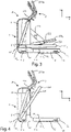
figure 3 shows an overall side view of the foldable gymnastic machine, shown infigure 1 , in the open configuration; -
figure 4 shows an overall side view of the foldable gymnastic machine, shown infigure 1 , in a partially closed configuration; -
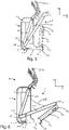
figure 5 shows an overall side view of the foldable gymnastic machine, shown infigure 1 , in a closed configuration; -
figure 6 shows an overall side view of the foldable gymnastic machine, in a transition position from the open configuration to the closed configuration, in the transition between the open configuration and the closed configuration; -
figure 7 shows a sectional side view of a component of the foldable gymnastic machine, shown infigure 1 , in a partially open position; -
figure 8 shows a sectional axonometric view of the component shown infigure 7 , in a partially open position; -
figure 9 shows a sectional side view of the component shown infigure 7 , in a safe open position; -
figure 10 shows a sectional axonometric view of a component of the foldable gymnastic machine, shown infigure 7 , in a safe open position; -
figure 11 shows a sectional side view of the component shown infigure 7 , in an open position; -
figure 12 shows a sectional axonometric view of the component shown infigure 7 , in an open position; -
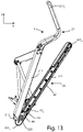
figure 13 shows a side view of an operating device of the machine shown infigure 1 , in a closed position; -
figure 14 shows a side view of the device shown infigure 13 , in a position of transition from the closed configuration to the opening configuration of the machine; -
figure 15 shows a sectional side view of the machine shown infigure 1 , in a partially open configuration; -
figure 16a shows a bottom view of a component of the machine shown infigure 1 , in a first position; and -
figure 16b shows a bottom view of the component shown infigure 16a , in a second position. - In the various figures, similar parts will be indicated with the same numerical references.
- With reference to the attached figures, the foldable gymnastic machine M object of the present invention comprises a
support structure 1, capable of supporting the gymnastic machine M itself, and anexercise device 2, coupled to saidsupport structure 1, which is capable of being operated by a user while performing a gymnastic exercise. - Said
support structure 1 comprises afront portion 11, and arear portion 12, coupled to saidfront portion 11, which extends along a horizontal direction X. - Said
front portion 11 has a L-shaped conformation, with a part extending along a vertical direction Y, perpendicular to said horizontal direction X, and abase 111, for supporting saidsupport structure 1. - Said
base 111 is provided with afirst end 111a and a second end 111b. - With particular reference now to
figures 5-12 , saidfront portion 11 comprises abase fulcrum 112, afirst contact area 113, with a bearing surface, and asupport element 114. - Said
base fulcrum 112 is arranged in saidsecond end 111b of saidbase 111. - Said
base fulcrum 112 allows the coupling between saidfront portion 11 and saidrear portion 12, so that saidrear portion 12 is able to rotate around saidbase fulcrum 112 with respect to saidportion front 11, on a plane parallel to the XY plane, identified by said horizontal X and vertical Y direction. - Said
first contact area 113 is capable of putting saidfront portion 11 into contact with a support surface, in particular the ground, and to support its weight. - Said
support element 114 is a semi-rigid support, arranged in thesecond end 111b of saidbase 111. - Said
support element 114 is able to support the weight of said gymnastic machine M and to deform more easily with respect to saidfirst contact area 113, to provide said gymnastic machine M with a planar support, even if the ground under said machine M is not planar. - In said
front portion 11 there is a resistant member, such as an electromagnetic brake, not shown in the figure, connected to saidoperating device 2. - Said electromagnetic brake is capable of opposing a resistance, variable and settable by the user, to said
exercise device 2, during the execution of the gymnastic exercise. - Said
rear portion 12 is provided with afirst end 12a and asecond end 12b. - Said
first end 12a of saidrear portion 12 is coupled to saidsecond end 111b of saidbase 111, by means of saidbase fulcrum 112, and it is able to rotate around saidbase fulcrum 112. - Said
rear portion 12 is able to pass from an open position, in which saidrear portion 12 is arranged along an axis parallel to said horizontal direction X and resting on the ground and in which it is possible to carry out a gymnastic exercise, to a closed position, in which it is arranged substantially vertically above saidbase fulcrum 112 and in which the bulk of said gymnastic machine M along said horizontal direction X is minimized, and vice versa. - Said
rear portion 12 may comprise a safety locking pin when it is in the closed position. - Said
rear portion 12 comprises asecond contact area 121 and asafety lock 3. - Said
rear portion 12 rests on the ground by means of saidsecond contact area 121. - Said
safety lock 3 is arranged in saidfirst end 12a of saidrear portion 12, and is capable of locking saidrear portion 12 in said open position. - Said
safety lock 3 is able to assume an open position, a safety position, as shown infigures 9 and10 , and a closed position. - With reference in particular to
figures 7-12 , saidsafety lock 3 is substantially an articulated-quadrilateral, which, following an actuation, causes the movement of the blocking means for blocking saidrear portion 12. - In particular, said
safety lock 3 comprises anactivation member 31, such as for example a lever or a handle, ajointed arm 32, amovable bulkhead 33, and a lockingmember 34. - Said
activation member 31 is operated by the user and is able to pass from a closed position, in which it locks saidrear portion 12 in the open position, to a safety position, in which saidrear portion 12 is already in the open position but is not yet unlocked, to an open position, in which saidrear portion 12 is in the closed position. - Said jointed
arm 32 is connected to saidactuation member 32 and it is capable of transferring movement from saidactivation member 31 to saidmovable bulkhead 33 in the different positions assumed by saidactivation member 31. - Said
movable bulkhead 33 is connected to said jointedarm 32 and is able to pass from a disengagement position, as shown infigures 7 and 8 , when saidactivation member 31 is in said open position, to an engagement position, as shown infigures 11 and 12 , when saidactivation member 31 is in said closed position, with said lockingmember 34, following the movement caused by said jointedarm 32, as will be described in detail below. - Said
safety lock 3 comprises an elastic element, such as for example a gas spring, not shown in the figure, coupled between saidbase fulcrum 112 and saidsupport structure 1, capable of facilitating the lifting of saidrear portion 12, from said open position towards said closed position, and supporting saidrear portion 12 in said closed position. - Referring now to
figures 13-16 , saidoperating device 2 comprises a first pair oflevers 21 for the hands and a second pair oflevers 22 for the feet, coupled to saidbase structure 1, and connected to said electromagnetic brake, which they are able to move when operated by the user during the execution of the gymnastic exercise. - Said first pair of hand levers 21 comprises a
first hand lever 211 and asecond hand lever 212. - In particular, said
first hand lever 211 comprises afirst end 211a, capable of being gripped by the hand of a user, and asecond end 211b. - Said
second hand lever 212 comprises afirst end 212a, capable of being gripped by the hand of a user, and asecond end 212b. - Without departing from the scope of protection of the present invention, said first ends 211a and 212a can also be coupled directly to said support structure and cannot be gripped by the user.
- Said first pair of
levers 21 for the hands is capable of oscillating on a plane parallel to said plane XY. - Said second pair of
levers 22 for the feet comprises afirst lever 221 for the feet and asecond lever 222 for the feet, each one of which is connected to said resistant member, such as an electromagnetic brake, arranged in saidfront portion 11, by respectively afirst cable 225 and asecond cable 226. - Said
first cable 225 andsecond cable 226 are tie rods, which act as end position for saidfirst lever 221 andsecond lever 222 when they are in the open position. - Said
first lever 221 for the feet is provided with afirst end 221a, coupled to saidsecond end 211b of saidfirst lever 211 for the hands, a secondfree end 221b, and a fulcrum of thelever 223, placed in saidfirst end 221a. - Said
second foot lever 222 is provided with afirst end 222a, coupled to saidsecond end 212b of saidsecond hand lever 212, a secondfree end 222b and a lever fulcrum 224, placed in saidfirst end 222a. - Each one of said
second end 221b of saidfirst foot lever 221 and saidsecond end 222b of saidsecond foot lever 222 is capable of accommodating a foot of a user while performing a gymnastic exercise. - Said second pair of
levers 22 for the feet is able to pass from an open position, wherein eachfirst lever 221 andsecond lever 222 is arranged along a direction substantially parallel to said horizontal direction X, and wherein it is possible to carry out a gymnastic exercise, wherein said first 225 and second 226 cables are in tension, in a closed position, wherein said first pair of hand levers 21 is approached and said first 225 and second 226 cables are slow. - Each of said first 221 and second 222 lever for the feet comprises a lock/
unlock mechanism 4, capable of respectively locking saidfirst lever 221 for the feet andsecond lever 222 for the feet in the closed position, and unlocking it, to allow the passage from the closed position to the open position. - For ease of description, the lock/
unlock mechanism 4 of saidfirst lever 221 for the feet is described, however also saidsecond lever 222 for the feet comprises an identical lock/unlock mechanism 4. - Referring in particular also to
figures 16 a and 16b, said lock/unlock mechanism 4 comprises ahandle 41, arranged in saidsecond end 221b of saidfirst lever 221 for the feet, atransmission element 42, which extends between said first 221a and second 222b end, apin 43 and anabutment element 44. - Said
handle 41 is able to pass from a rest position to a working position, in which it activates said lock/unlock mechanism 4, and vice versa. - Said lock/
unlock mechanism 4 can comprise an unlocking pin to enable saidhandle 41. - Said
transmission element 42 is provided with afirst end 42a, arranged in saidsecond end 221b of saidfirst lever 221 for the feet, capable of being connected to saidhandle 41, and asecond end 42b, arranged in saidfirst end 221a of saidfirst foot lever 221, which saidpin 43 is coupled to. - In correspondence with said
second end 221b, aspring 45 is arranged, capable of pushing saidpin 43 towards saidabutment element 44. - Said
abutment element 44 is integral with saidfirst lever 211 of said first pair oflevers 21 for the hands. - Said
abutment element 44 has an external surface and a cavity, which is able to house saidpin 43 in the closed position of saidfirst lever 221. - Said
transmission element 42 is able to actuate saidpin 43, towards and away from saidabutment element 44. - In particular, when said
first lever 221 is in the open position, saidpin 43 is distant from saidabutment element 44, while passing from the open position to the closed position it is capable of sliding on the surface of saidabutment element 44, remaining in contact with saidabutment element 44 thanks to the force exerted by saidspring 45, and in the closed position it is housed in the cavity of saidabutment element 44, due to the force exerted by saidspring 45. - During the execution of a gymnastic exercise, each end of the lever of said second pair of
levers 22 is capable of moving along an elliptical trajectory on a plane parallel to said XY plane. - Said first fulcrum of the
lever 223 is capable of rotatably coupling saidfirst lever 221 for the feet with saidfirst lever 211 for the hands, to allow the relative movement of saidfirst lever 221 for the feet with respect to saidfirst lever 211 for the hands, for the execution of the exercise and the passage of saidfirst lever 221 for the feet from the open position to the closed position and vice versa. - Similarly, said lever fulcrum 224 is capable of rotatably coupling said
second lever 222 for the feet with saidsecond lever 212 for the hands, to allow the relative movement of saidsecond lever 222 for the feet with respect to saidsecond lever 212 for the hands, for the execution of the exercise and the passage of saidsecond lever 222 for the feet from the open position to the closed position and vice versa. - Said gymnastic machine M is in an open configuration when said
rear portion 12 is in the open position and said second pair oflevers 22 is in the open position. - Said gymnastic machine M is in a closed configuration when said
rear portion 12 is in closed position and said second pair oflevers 22 is in closed position. - Referring in particular to
figure 6 , the passage of saidfirst lever 221 for the feet andsecond lever 222 for the hands, from said open position to said closed position, can also take place simultaneously and due to the passage of saidrear portion 12 from said open position to said closed position. - The operation of the foldable gymnastic machine M, object of the present invention described above, is as follows.
- When a user wishes to carry out a stationary simulation walking or running gymnastic exercise, he/she accesses said gymnastic machine M in an open configuration.
- In particular, the user positions his/her feet on said second pair of
levers 22 for the feet and his/her hands on said first pair oflevers 21 for the hands, gripping saidfirst end 211a of saidfirst lever 211 for the hands and saidfirst end 212a of saidsecond hand lever 212. - The user then begins to move said second pair of
levers 22 for the feet and said first pair oflevers 21 for the hands, simulating the movement of a walk or run. - The movements performed during the gymnastic exercise are made tiring by said electromagnetic brake, which opposes the movement of said
exercise device 2. - When the user has finished the gymnastic exercise, he/she gets off said gymnastic machine M.
- To reduce the encumbrance along said horizontal direction X of said gymnastic machine M, when not in use, the user moves the gymnastic machine M from said open configuration to said closed configuration.
- To this end, in particular, the user moves first said second pair of
levers 22 from said open position to said closed position, and then saidrear portion 12 from said open position to said closed position. - Even more particularly, the user raises said second pair of
levers 22 for the feet bringing it towards said first pair oflevers 21. - For each one of said first 221 and second 222 lever for the feet, said
pin 43 slides on the surface of saidabutment element 44, until it reaches the cavity of saidabutment element 44 and is positioned inside it pushed by saidspring 45, to ensure the blocking of said second pair oflevers 22 for the feet, in the closed position. - Subsequently, the user activates said
safety lock 3. - In particular, the user activates said
activation member 31 to make it pass from said closed position to said safety position. - Subsequently, the user passes said
activation member 31 from said safety position to said open position. - In particular, said jointed
arm 32 transfers the movement from saidactivation member 31 to saidmovable bulkhead 33. - Said
mobile bulkhead 33 then passes from said engagement position with said lockingmember 34 to said disengagement position. - Said
rear portion 12 is consequently capable of passing to said closed position. - In particular, the user lifts said
second end 12b of saidrear portion 12, which rotates around saidbase fulcrum 112 until it is arranged substantially vertically above saidbase fulcrum 112. - If there is a locking pin, said
rear portion 12 remains locked in said closed position. - Said gymnastic machine M is therefore in said closed configuration, in which said
rear portion 12 is in the closed position and said second pair oflevers 22 is in the closed position. - When the user intends to perform a gymnastic exercise again, he/she first passes said
rear portion 12 from said closed position to said open position. - In particular, the user grasps said
second end 12b of saidrear portion 12 and makes it rotate around saidbase fulcrum 112 until it is arranged in proximity to the supporting surface. - Said
activation member 31 automatically passes into said safety position, in which saidrear portion 12 is already in the open position, but it has not yet been locked. - Furthermore, said
movable bulkhead 33 passes from said disengagement position to said engagement position, with said lockingmember 34. - The user then exerts a force on said
activation member 31 to make it pass from said safety position to said closed position, in which it locks saidrear portion 12 in the open position. - In the passage from said safety position to said closed position of said
activation member 31, saidsupport element 114 is deformed, so as to provide said gymnastic machine M with a planar support, even in the case in which the ground underlying said gymnastic machine M is not planar. - The user then passes said second pair of
levers 22 from said closed position to said open position. - In particular, the user passes said
handle 41 of said locking/unlockingmechanism 4 from said rest position to said working position. - Said
handle 41 then actuates, through saidtransmission element 42, saidpin 43, moving it away from saidabutment element 44. - Said
first lever 221 of said second pair oflevers 22 can therefore pass from said closed position to said open position. - In particular, said
first lever 221 of said second pair oflevers 22 is lowered by the user, by rotating around said first fulcrum oflever 223 until said open position is reached, in which saidfirst cable 225 is under tension. - The same procedure is repeated with said
second lever 222 of said second pair oflevers 22. - In particular, the user operates said locking/unlocking mechanism of said
second lever 222. - Said
second lever 222 of said second pair oflevers 22 can therefore pass from said closed position to said open position. - Even more particularly, said
second lever 222 of said second pair oflevers 22 is lowered by the user, by rotating around said second lever fulcrum 224 until said open position is reached, in which saidsecond cable 226 is under tension. - Said second pair of
levers 22 is therefore in said open position and said gymnastic machine M is in said open configuration. - The user can then access said gymnastic machine M again in an open configuration and perform a gymnastic exercise.
- In a second embodiment, it is also possible that the transition from the open configuration to the closed configuration of said gymnastic machine M takes place by simultaneously bringing said
rear portion 12 and said second pair oflevers 22 from the open position to the closed position. - In this case, in particular, the user initially moves said
rear portion 12 from said open position towards said closed position. - At the same time, said
rear portion 12 comes into contact with said second pair oflevers 22 and therefore together continue the passage towards said closed position until said gymnastic machine M is in a closed configuration. - A first advantage of the gymnastic machine M according to the present invention is the possibility of having a foldable gymnastic machine, capable of passing from an open configuration to a closed configuration, having reduced longitudinal overall dimensions.
- Another advantage of the present invention is the possibility of having a machine that allows a transition from the open configuration to the closed one and vice versa, which is not tiring.
- A further advantage of the gymnastic machine M according to the present invention is the possibility of having safety devices, which protect the user in the passage from the open configuration to the closed configuration and vice versa.
Claims (12)
- Foldable gymnastic machine (M) comprisinga supporting structure (1) to rest said gymnastic machine (M) on a resting surface, comprisinga front portion (11), comprising, in turn, a resistance member, and a rear portion (12),an exercise device (2), through which a user performs a gymnastic exercise, coupled to said supporting structure (1) and to said resistance member, capable of resisting during the execution of a gymnastic exercise, said exercise device (2) comprisinga second pair of levers (22) for the feet,in turn comprising a first (221) and a second (222) lever, each provided with a first end (221a; 222a), coupled to said supporting structure (1), and a free second end (221b; 222b), capable of fitting said user's feet during the execution of the gymnastic exercise,said gymnastic machine (M) being characterized in that said first (221) and second (221) lever of said second pair of levers (22) for the feet are capable of passing from an open position, in which the user can perform the gymnastic exercise, to a closed position, when the gymnastic machine (M) is not in use.
- Gymnastic machine (M) according to the previous claim, characterized in that said rear portion (12) is capable of passing from an open position, when it is placed in contact with said resting surface and positioned along a horizontal direction (X), to a closed position when it is placed close to said front portion (11), substantially placed along a vertical direction (Y), orthogonal to said horizontal direction (X).
- Gymnastic machine (M) according to the previous claim, characterized in that said rear portion (12) is capable of getting into a safety position, while passing from said open position to said closed position, before permanently getting into the open position.
- Gymnastic machine (M) according to the previous claim, characterized in that said rear portion (12) comprises a safety lock (3), capable of locking said rear portion (12) in said open position and in said safety position.
- Gymnastic machine (M) according to the previous claim, characterized in that said safety lock (3) comprises an activation group (31; 32) and a locking group (33; 34), linked to said activation group (31; 32), capable of locking said rear portion (12) in said open position and of unlocking said rear portion (12) to pass from said open position to said closed position.
- Gymnastic machine (M) according to the previous claim, characterized in that said activation group (31; 32) comprisesan activation member (31), capable of being activated by the user to pass from a closing position, in which said rear portion (12) is locked in the open position, to a safety position, in which said rear portion (12) is in the safety position, to an opening position, in which said rear portion (12) is in the closed position,a jointed arm (32), connected to said activation member (31), capable of transferring the movement from said activation member (31) to said locking group (33; 34), in the several positions assumed by said activation member (31).
- Gymnastic machine (M) according to the previous claim, characterized in that said locking group (33; 34) comprisesa locking member (34), anda movable bulkhead (33), connected to said jointed arm (32), and capable of passing from a disengagement position, when said activation member (31) is in said opening position, to an engagement position, when said activation member (31) is in said closing position, with said locking member (34), following the movement caused by said jointed arm (32).
- Gymnastic machine (M) according to any one of the previous claims, characterized in that said first (221) and second (222) lever comprise a lock/unlock mechanism (4) capable of allowing the passing of said first (221) and second (222) lever for the feet from the open position to the closed position and vice versa.
- Gymnastic machine (M) according to the previous claim, characterized in that said lock/unlock mechanism (4) comprisesa handle (41), capable of being used by the user to pass from a resting position to a working position, wherein said lock/unlock mechanism (4) is activated,a transmission element (42), connected to said handle (41) and operated by the handle (41) itself,a pin (43) connected to said transmission element (42) and movable in an integral way with it, andan abutment element (44), capable of receiving said pin (43) in the closed position of said first (221) and second (222) lever for the feet.
- Gymnastic machine (M) according to any one of the previous claims, characterized in that it comprises a first pair of levers (21) for the hands, capable of supporting the upper limbs of a user, coupled to said second pair of levers (22) for the feet.
- Gymnastic machine (M) according to any one of the previous claims, characterized in that the passage of said rear portion (12) from said open position to said closed position is capable of causing the passage of said second pair of levers (22) for the feet from said open position to said closed position.
- Gymnastic machine (M) according to any one of the previous claims, characterized in that said second pair of levers (22) for the feet is coupled to said resistance member via a first (225) and a second (226) cable, in such a way that during the execution of a gymnastic exercise, each lever of said second pair of levers (22) is capable of following an elliptical trajectory.
Applications Claiming Priority (1)
| Application Number | Priority Date | Filing Date | Title |
|---|---|---|---|
| IT102021000017516A IT202100017516A1 (en) | 2021-07-02 | 2021-07-02 | Foldable exercise machine. |
Publications (2)
| Publication Number | Publication Date |
|---|---|
| EP4112135A1 true EP4112135A1 (en) | 2023-01-04 |
| EP4112135B1 EP4112135B1 (en) | 2025-01-15 |
Family
ID=77802154
Family Applications (1)
| Application Number | Title | Priority Date | Filing Date |
|---|---|---|---|
| EP22182488.1A Active EP4112135B1 (en) | 2021-07-02 | 2022-07-01 | Foldable gymnastic machine |
Country Status (4)
| Country | Link |
|---|---|
| US (1) | US12194338B2 (en) |
| EP (1) | EP4112135B1 (en) |
| CN (1) | CN115554656A (en) |
| IT (1) | IT202100017516A1 (en) |
Citations (4)
| Publication number | Priority date | Publication date | Assignee | Title |
|---|---|---|---|---|
| US7736279B2 (en) * | 2007-02-20 | 2010-06-15 | Icon Ip, Inc. | One-step foldable elliptical exercise machine |
| US9067094B2 (en) * | 2013-03-13 | 2015-06-30 | Johnson Health Tech Co., Ltd. | Exercise apparatus |
| EP3159046A1 (en) * | 2015-10-23 | 2017-04-26 | Technogym S.p.A. | Foldable sliding belt gymnastic machine |
| WO2019089547A1 (en) * | 2017-10-31 | 2019-05-09 | Nautilus, Inc. | Exercise machine |
Family Cites Families (18)
| Publication number | Priority date | Publication date | Assignee | Title |
|---|---|---|---|---|
| US5692994A (en) * | 1995-06-08 | 1997-12-02 | Eschenbach; Paul William | Collapsible exercise machine with arm exercise |
| US5782722A (en) * | 1997-08-27 | 1998-07-21 | Sands; Lenny | Structure of folding collapsible step exerciser |
| US6030320A (en) * | 1998-01-12 | 2000-02-29 | Stearns; Kenneth W. | Collapsible exercise apparatus |
| US6149551A (en) * | 1998-05-12 | 2000-11-21 | Epix, Inc. | Foldable elliptical exercise machine |
| US6135927A (en) * | 1999-10-29 | 2000-10-24 | Lo; Kun-Chuan | Foldable exerciser |
| US7468021B2 (en) | 2002-08-06 | 2008-12-23 | True Fitness Technology, Inc. | Compact elliptical exercise machine with adjustable stride length |
| US7060005B2 (en) * | 2004-01-05 | 2006-06-13 | Diamondback Fitness, Inc. | Exercise device |
| US7766797B2 (en) * | 2004-08-11 | 2010-08-03 | Icon Ip, Inc. | Breakaway or folding elliptical exercise machine |
| TWM287690U (en) * | 2005-09-09 | 2006-02-21 | Chiu-Hsiang Lo | Ellipse exercise machine featuring adjustable inclined angle |
| US7854691B2 (en) * | 2006-08-02 | 2010-12-21 | Johnson Health Tech Co., Ltd. | Exercise apparatus |
| US20080280733A1 (en) * | 2007-05-09 | 2008-11-13 | Spark Innovations, Inc. | Folding elliptical exercise machine |
| US7513855B1 (en) * | 2007-10-11 | 2009-04-07 | Proteus Sports Inc. | Folding exercising machine |
| TW201105383A (en) * | 2009-08-13 | 2011-02-16 | Johnson Health Tech Co Ltd | Foldable elliptical exercise machine |
| US8628454B2 (en) | 2011-06-20 | 2014-01-14 | Strength Master Fitness Tech Co., Ltd. | Sports training machine and control method thereof |
| TWI449555B (en) * | 2012-05-18 | 2014-08-21 | Collapsible elliptical sports machine | |
| US8944966B2 (en) * | 2013-04-02 | 2015-02-03 | Larry D. Miller Trust | Variable stride exercise device |
| WO2014201296A1 (en) * | 2013-06-13 | 2014-12-18 | Icon Health & Fitness, Inc. | Folding elliptical stabilization system |
| US9498672B1 (en) | 2015-11-23 | 2016-11-22 | Larry D. Miller Trust | Elliptical exercise device with moving control tracks |
-
2021
- 2021-07-02 IT IT102021000017516A patent/IT202100017516A1/en unknown
-
2022
- 2022-07-01 US US17/810,403 patent/US12194338B2/en active Active
- 2022-07-01 EP EP22182488.1A patent/EP4112135B1/en active Active
- 2022-07-01 CN CN202210775293.5A patent/CN115554656A/en active Pending
Patent Citations (4)
| Publication number | Priority date | Publication date | Assignee | Title |
|---|---|---|---|---|
| US7736279B2 (en) * | 2007-02-20 | 2010-06-15 | Icon Ip, Inc. | One-step foldable elliptical exercise machine |
| US9067094B2 (en) * | 2013-03-13 | 2015-06-30 | Johnson Health Tech Co., Ltd. | Exercise apparatus |
| EP3159046A1 (en) * | 2015-10-23 | 2017-04-26 | Technogym S.p.A. | Foldable sliding belt gymnastic machine |
| WO2019089547A1 (en) * | 2017-10-31 | 2019-05-09 | Nautilus, Inc. | Exercise machine |
Also Published As
| Publication number | Publication date |
|---|---|
| EP4112135B1 (en) | 2025-01-15 |
| IT202100017516A1 (en) | 2023-01-02 |
| US12194338B2 (en) | 2025-01-14 |
| US20230001264A1 (en) | 2023-01-05 |
| CN115554656A (en) | 2023-01-03 |
Similar Documents
| Publication | Publication Date | Title |
|---|---|---|
| US9457219B2 (en) | Squat exercise apparatus | |
| US4563003A (en) | Weight lifting apparatus having increased force on the return stroke | |
| EP3159046A1 (en) | Foldable sliding belt gymnastic machine | |
| US5669859A (en) | Weightlifting apparatus | |
| US8968159B2 (en) | Folding elliptical exercise machine | |
| JP6661209B2 (en) | Weight distribution ratio device for weight machines | |
| US4542899A (en) | Exercise device | |
| CN102971051B (en) | Change of direction machine and method of training therefor | |
| EP1276543B1 (en) | Exercise apparatus | |
| US6251052B1 (en) | Squat exercise apparatus | |
| US4982952A (en) | Simulated climbing exercise device | |
| KR20150111346A (en) | Exercise apparatus having a slidable weight bar assembly | |
| US20070022666A1 (en) | Child safety barrier with a locking device | |
| EP4112135B1 (en) | Foldable gymnastic machine | |
| KR101219207B1 (en) | hinged door assembly | |
| CN101637645B (en) | Multi-functional training equipment that can also train the muscles of the fingers | |
| WO2000040199A8 (en) | Rehabilitation apparatus | |
| KR101369467B1 (en) | A complex indoor fitness equipment | |
| GB2459791A (en) | Apparatus to assist traversal of stairs in which a handle initiates an increment of movement | |
| KR20220068897A (en) | squat machine | |
| US12239873B2 (en) | Weight elevation systems, methods, and devices | |
| EP1633670B1 (en) | Tilt mechanism for the movable part of a stairlift guide | |
| EP4430253B1 (en) | Assembly comprising a folding ladder and a platform | |
| GB2073111A (en) | Stair climbing trucks | |
| CN111991775A (en) | Handstand training device |
Legal Events
| Date | Code | Title | Description |
|---|---|---|---|
| PUAI | Public reference made under article 153(3) epc to a published international application that has entered the european phase |
Free format text: ORIGINAL CODE: 0009012 |
|
| STAA | Information on the status of an ep patent application or granted ep patent |
Free format text: STATUS: THE APPLICATION HAS BEEN PUBLISHED |
|
| AK | Designated contracting states |
Kind code of ref document: A1 Designated state(s): AL AT BE BG CH CY CZ DE DK EE ES FI FR GB GR HR HU IE IS IT LI LT LU LV MC MK MT NL NO PL PT RO RS SE SI SK SM TR |
|
| P01 | Opt-out of the competence of the unified patent court (upc) registered |
Effective date: 20230511 |
|
| STAA | Information on the status of an ep patent application or granted ep patent |
Free format text: STATUS: REQUEST FOR EXAMINATION WAS MADE |
|
| 17P | Request for examination filed |
Effective date: 20230627 |
|
| RBV | Designated contracting states (corrected) |
Designated state(s): AL AT BE BG CH CY CZ DE DK EE ES FI FR GB GR HR HU IE IS IT LI LT LU LV MC MK MT NL NO PL PT RO RS SE SI SK SM TR |
|
| GRAP | Despatch of communication of intention to grant a patent |
Free format text: ORIGINAL CODE: EPIDOSNIGR1 |
|
| STAA | Information on the status of an ep patent application or granted ep patent |
Free format text: STATUS: GRANT OF PATENT IS INTENDED |
|
| RIC1 | Information provided on ipc code assigned before grant |
Ipc: A63B 22/06 20060101AFI20240502BHEP |
|
| INTG | Intention to grant announced |
Effective date: 20240522 |
|
| GRAJ | Information related to disapproval of communication of intention to grant by the applicant or resumption of examination proceedings by the epo deleted |
Free format text: ORIGINAL CODE: EPIDOSDIGR1 |
|
| STAA | Information on the status of an ep patent application or granted ep patent |
Free format text: STATUS: REQUEST FOR EXAMINATION WAS MADE |
|
| GRAP | Despatch of communication of intention to grant a patent |
Free format text: ORIGINAL CODE: EPIDOSNIGR1 |
|
| STAA | Information on the status of an ep patent application or granted ep patent |
Free format text: STATUS: GRANT OF PATENT IS INTENDED |
|
| INTG | Intention to grant announced |
Effective date: 20240924 |
|
| GRAJ | Information related to disapproval of communication of intention to grant by the applicant or resumption of examination proceedings by the epo deleted |
Free format text: ORIGINAL CODE: EPIDOSDIGR1 |
|
| STAA | Information on the status of an ep patent application or granted ep patent |
Free format text: STATUS: REQUEST FOR EXAMINATION WAS MADE |
|
| GRAP | Despatch of communication of intention to grant a patent |
Free format text: ORIGINAL CODE: EPIDOSNIGR1 |
|
| STAA | Information on the status of an ep patent application or granted ep patent |
Free format text: STATUS: GRANT OF PATENT IS INTENDED |
|
| GRAS | Grant fee paid |
Free format text: ORIGINAL CODE: EPIDOSNIGR3 |
|
| GRAA | (expected) grant |
Free format text: ORIGINAL CODE: 0009210 |
|
| STAA | Information on the status of an ep patent application or granted ep patent |
Free format text: STATUS: THE PATENT HAS BEEN GRANTED |
|
| INTC | Intention to grant announced (deleted) | ||
| INTG | Intention to grant announced |
Effective date: 20241127 |
|
| AK | Designated contracting states |
Kind code of ref document: B1 Designated state(s): AL AT BE BG CH CY CZ DE DK EE ES FI FR GB GR HR HU IE IS IT LI LT LU LV MC MK MT NL NO PL PT RO RS SE SI SK SM TR |
|
| REG | Reference to a national code |
Ref country code: CH Ref legal event code: EP Ref country code: GB Ref legal event code: FG4D |
|
| REG | Reference to a national code |
Ref country code: DE Ref legal event code: R096 Ref document number: 602022009512 Country of ref document: DE |
|
| REG | Reference to a national code |
Ref country code: IE Ref legal event code: FG4D |
|
| RAP4 | Party data changed (patent owner data changed or rights of a patent transferred) |
Owner name: TECHNOGYM S.P.A. |
|
| REG | Reference to a national code |
Ref country code: NL Ref legal event code: MP Effective date: 20250115 |
|
| PG25 | Lapsed in a contracting state [announced via postgrant information from national office to epo] |
Ref country code: NL Free format text: LAPSE BECAUSE OF FAILURE TO SUBMIT A TRANSLATION OF THE DESCRIPTION OR TO PAY THE FEE WITHIN THE PRESCRIBED TIME-LIMIT Effective date: 20250115 |
|
| PG25 | Lapsed in a contracting state [announced via postgrant information from national office to epo] |
Ref country code: RS Free format text: LAPSE BECAUSE OF FAILURE TO SUBMIT A TRANSLATION OF THE DESCRIPTION OR TO PAY THE FEE WITHIN THE PRESCRIBED TIME-LIMIT Effective date: 20250415 |
|
| PG25 | Lapsed in a contracting state [announced via postgrant information from national office to epo] |
Ref country code: FI Free format text: LAPSE BECAUSE OF FAILURE TO SUBMIT A TRANSLATION OF THE DESCRIPTION OR TO PAY THE FEE WITHIN THE PRESCRIBED TIME-LIMIT Effective date: 20250115 |
|
| PG25 | Lapsed in a contracting state [announced via postgrant information from national office to epo] |
Ref country code: PL Free format text: LAPSE BECAUSE OF FAILURE TO SUBMIT A TRANSLATION OF THE DESCRIPTION OR TO PAY THE FEE WITHIN THE PRESCRIBED TIME-LIMIT Effective date: 20250115 |
|
| PG25 | Lapsed in a contracting state [announced via postgrant information from national office to epo] |
Ref country code: ES Free format text: LAPSE BECAUSE OF FAILURE TO SUBMIT A TRANSLATION OF THE DESCRIPTION OR TO PAY THE FEE WITHIN THE PRESCRIBED TIME-LIMIT Effective date: 20250115 |
|
| REG | Reference to a national code |
Ref country code: LT Ref legal event code: MG9D |
|
| PG25 | Lapsed in a contracting state [announced via postgrant information from national office to epo] |
Ref country code: IS Free format text: LAPSE BECAUSE OF FAILURE TO SUBMIT A TRANSLATION OF THE DESCRIPTION OR TO PAY THE FEE WITHIN THE PRESCRIBED TIME-LIMIT Effective date: 20250515 Ref country code: NO Free format text: LAPSE BECAUSE OF FAILURE TO SUBMIT A TRANSLATION OF THE DESCRIPTION OR TO PAY THE FEE WITHIN THE PRESCRIBED TIME-LIMIT Effective date: 20250415 |
|
| REG | Reference to a national code |
Ref country code: AT Ref legal event code: MK05 Ref document number: 1759470 Country of ref document: AT Kind code of ref document: T Effective date: 20250115 |
|
| PG25 | Lapsed in a contracting state [announced via postgrant information from national office to epo] |
Ref country code: HR Free format text: LAPSE BECAUSE OF FAILURE TO SUBMIT A TRANSLATION OF THE DESCRIPTION OR TO PAY THE FEE WITHIN THE PRESCRIBED TIME-LIMIT Effective date: 20250115 |
|
| PG25 | Lapsed in a contracting state [announced via postgrant information from national office to epo] |
Ref country code: LV Free format text: LAPSE BECAUSE OF FAILURE TO SUBMIT A TRANSLATION OF THE DESCRIPTION OR TO PAY THE FEE WITHIN THE PRESCRIBED TIME-LIMIT Effective date: 20250115 Ref country code: PT Free format text: LAPSE BECAUSE OF FAILURE TO SUBMIT A TRANSLATION OF THE DESCRIPTION OR TO PAY THE FEE WITHIN THE PRESCRIBED TIME-LIMIT Effective date: 20250515 |
|
| PG25 | Lapsed in a contracting state [announced via postgrant information from national office to epo] |
Ref country code: GR Free format text: LAPSE BECAUSE OF FAILURE TO SUBMIT A TRANSLATION OF THE DESCRIPTION OR TO PAY THE FEE WITHIN THE PRESCRIBED TIME-LIMIT Effective date: 20250416 Ref country code: BG Free format text: LAPSE BECAUSE OF FAILURE TO SUBMIT A TRANSLATION OF THE DESCRIPTION OR TO PAY THE FEE WITHIN THE PRESCRIBED TIME-LIMIT Effective date: 20250115 |
|
| PG25 | Lapsed in a contracting state [announced via postgrant information from national office to epo] |
Ref country code: AT Free format text: LAPSE BECAUSE OF FAILURE TO SUBMIT A TRANSLATION OF THE DESCRIPTION OR TO PAY THE FEE WITHIN THE PRESCRIBED TIME-LIMIT Effective date: 20250115 |
|
| PG25 | Lapsed in a contracting state [announced via postgrant information from national office to epo] |
Ref country code: SE Free format text: LAPSE BECAUSE OF FAILURE TO SUBMIT A TRANSLATION OF THE DESCRIPTION OR TO PAY THE FEE WITHIN THE PRESCRIBED TIME-LIMIT Effective date: 20250115 |
|
| PG25 | Lapsed in a contracting state [announced via postgrant information from national office to epo] |
Ref country code: SM Free format text: LAPSE BECAUSE OF FAILURE TO SUBMIT A TRANSLATION OF THE DESCRIPTION OR TO PAY THE FEE WITHIN THE PRESCRIBED TIME-LIMIT Effective date: 20250115 |
|
| PG25 | Lapsed in a contracting state [announced via postgrant information from national office to epo] |
Ref country code: DK Free format text: LAPSE BECAUSE OF FAILURE TO SUBMIT A TRANSLATION OF THE DESCRIPTION OR TO PAY THE FEE WITHIN THE PRESCRIBED TIME-LIMIT Effective date: 20250115 |
|
| PGFP | Annual fee paid to national office [announced via postgrant information from national office to epo] |
Ref country code: DE Payment date: 20250728 Year of fee payment: 4 |
|
| PGFP | Annual fee paid to national office [announced via postgrant information from national office to epo] |
Ref country code: IT Payment date: 20250731 Year of fee payment: 4 |
|
| REG | Reference to a national code |
Ref country code: DE Ref legal event code: R097 Ref document number: 602022009512 Country of ref document: DE |
|
| PGFP | Annual fee paid to national office [announced via postgrant information from national office to epo] |
Ref country code: FR Payment date: 20250725 Year of fee payment: 4 |
|
| PG25 | Lapsed in a contracting state [announced via postgrant information from national office to epo] |
Ref country code: CZ Free format text: LAPSE BECAUSE OF FAILURE TO SUBMIT A TRANSLATION OF THE DESCRIPTION OR TO PAY THE FEE WITHIN THE PRESCRIBED TIME-LIMIT Effective date: 20250115 Ref country code: EE Free format text: LAPSE BECAUSE OF FAILURE TO SUBMIT A TRANSLATION OF THE DESCRIPTION OR TO PAY THE FEE WITHIN THE PRESCRIBED TIME-LIMIT Effective date: 20250115 |
|
| PG25 | Lapsed in a contracting state [announced via postgrant information from national office to epo] |
Ref country code: RO Free format text: LAPSE BECAUSE OF FAILURE TO SUBMIT A TRANSLATION OF THE DESCRIPTION OR TO PAY THE FEE WITHIN THE PRESCRIBED TIME-LIMIT Effective date: 20250115 |
|
| PG25 | Lapsed in a contracting state [announced via postgrant information from national office to epo] |
Ref country code: SK Free format text: LAPSE BECAUSE OF FAILURE TO SUBMIT A TRANSLATION OF THE DESCRIPTION OR TO PAY THE FEE WITHIN THE PRESCRIBED TIME-LIMIT Effective date: 20250115 |
|
| PLBE | No opposition filed within time limit |
Free format text: ORIGINAL CODE: 0009261 |
|
| STAA | Information on the status of an ep patent application or granted ep patent |
Free format text: STATUS: NO OPPOSITION FILED WITHIN TIME LIMIT |
|
| REG | Reference to a national code |
Ref country code: CH Ref legal event code: L10 Free format text: ST27 STATUS EVENT CODE: U-0-0-L10-L00 (AS PROVIDED BY THE NATIONAL OFFICE) Effective date: 20251126 |
|
| 26N | No opposition filed |
Effective date: 20251016 |
|
| REG | Reference to a national code |
Ref country code: CH Ref legal event code: H13 Free format text: ST27 STATUS EVENT CODE: U-0-0-H10-H13 (AS PROVIDED BY THE NATIONAL OFFICE) Effective date: 20260224 |
|
| PG25 | Lapsed in a contracting state [announced via postgrant information from national office to epo] |
Ref country code: LU Free format text: LAPSE BECAUSE OF NON-PAYMENT OF DUE FEES Effective date: 20250701 |
|
| REG | Reference to a national code |
Ref country code: BE Ref legal event code: MM Effective date: 20250731 |
|
| PG25 | Lapsed in a contracting state [announced via postgrant information from national office to epo] |
Ref country code: BE Free format text: LAPSE BECAUSE OF NON-PAYMENT OF DUE FEES Effective date: 20250731 |
|
| PG25 | Lapsed in a contracting state [announced via postgrant information from national office to epo] |
Ref country code: CH Free format text: LAPSE BECAUSE OF NON-PAYMENT OF DUE FEES Effective date: 20250731 |