EP4112026A1 - Composite web - Google Patents
Composite web Download PDFInfo
- Publication number
- EP4112026A1 EP4112026A1 EP22180490.9A EP22180490A EP4112026A1 EP 4112026 A1 EP4112026 A1 EP 4112026A1 EP 22180490 A EP22180490 A EP 22180490A EP 4112026 A1 EP4112026 A1 EP 4112026A1
- Authority
- EP
- European Patent Office
- Prior art keywords
- segment
- continuous web
- moulded
- web
- moulded segment
- Prior art date
- Legal status (The legal status is an assumption and is not a legal conclusion. Google has not performed a legal analysis and makes no representation as to the accuracy of the status listed.)
- Granted
Links
Images


Classifications
-
- A—HUMAN NECESSITIES
- A61—MEDICAL OR VETERINARY SCIENCE; HYGIENE
- A61F—FILTERS IMPLANTABLE INTO BLOOD VESSELS; PROSTHESES; DEVICES PROVIDING PATENCY TO, OR PREVENTING COLLAPSING OF, TUBULAR STRUCTURES OF THE BODY, e.g. STENTS; ORTHOPAEDIC, NURSING OR CONTRACEPTIVE DEVICES; FOMENTATION; TREATMENT OR PROTECTION OF EYES OR EARS; BANDAGES, DRESSINGS OR ABSORBENT PADS; FIRST-AID KITS
- A61F13/00—Bandages or dressings; Absorbent pads
- A61F13/15—Absorbent pads, e.g. sanitary towels, swabs or tampons for external or internal application to the body; Supporting or fastening means therefor; Tampon applicators
- A61F13/15577—Apparatus or processes for manufacturing
- A61F13/15699—Forming webs by bringing together several webs, e.g. by laminating or folding several webs, with or without additional treatment of the webs
-
- A—HUMAN NECESSITIES
- A61—MEDICAL OR VETERINARY SCIENCE; HYGIENE
- A61F—FILTERS IMPLANTABLE INTO BLOOD VESSELS; PROSTHESES; DEVICES PROVIDING PATENCY TO, OR PREVENTING COLLAPSING OF, TUBULAR STRUCTURES OF THE BODY, e.g. STENTS; ORTHOPAEDIC, NURSING OR CONTRACEPTIVE DEVICES; FOMENTATION; TREATMENT OR PROTECTION OF EYES OR EARS; BANDAGES, DRESSINGS OR ABSORBENT PADS; FIRST-AID KITS
- A61F13/00—Bandages or dressings; Absorbent pads
- A61F13/15—Absorbent pads, e.g. sanitary towels, swabs or tampons for external or internal application to the body; Supporting or fastening means therefor; Tampon applicators
- A61F13/15577—Apparatus or processes for manufacturing
- A61F13/15707—Mechanical treatment, e.g. notching, twisting, compressing, shaping
- A61F13/15731—Treating webs, e.g. for giving them a fibrelike appearance, e.g. by embossing
-
- A—HUMAN NECESSITIES
- A61—MEDICAL OR VETERINARY SCIENCE; HYGIENE
- A61F—FILTERS IMPLANTABLE INTO BLOOD VESSELS; PROSTHESES; DEVICES PROVIDING PATENCY TO, OR PREVENTING COLLAPSING OF, TUBULAR STRUCTURES OF THE BODY, e.g. STENTS; ORTHOPAEDIC, NURSING OR CONTRACEPTIVE DEVICES; FOMENTATION; TREATMENT OR PROTECTION OF EYES OR EARS; BANDAGES, DRESSINGS OR ABSORBENT PADS; FIRST-AID KITS
- A61F13/00—Bandages or dressings; Absorbent pads
- A61F13/15—Absorbent pads, e.g. sanitary towels, swabs or tampons for external or internal application to the body; Supporting or fastening means therefor; Tampon applicators
- A61F13/15577—Apparatus or processes for manufacturing
- A61F13/15707—Mechanical treatment, e.g. notching, twisting, compressing, shaping
- A61F13/15739—Sealing, e.g. involving cutting
-
- B—PERFORMING OPERATIONS; TRANSPORTING
- B32—LAYERED PRODUCTS
- B32B—LAYERED PRODUCTS, i.e. PRODUCTS BUILT-UP OF STRATA OF FLAT OR NON-FLAT, e.g. CELLULAR OR HONEYCOMB, FORM
- B32B3/00—Layered products comprising a layer with external or internal discontinuities or unevennesses, or a layer of non-planar shape; Layered products comprising a layer having particular features of form
- B32B3/26—Layered products comprising a layer with external or internal discontinuities or unevennesses, or a layer of non-planar shape; Layered products comprising a layer having particular features of form characterised by a particular shape of the outline of the cross-section of a continuous layer; characterised by a layer with cavities or internal voids ; characterised by an apertured layer
- B32B3/28—Layered products comprising a layer with external or internal discontinuities or unevennesses, or a layer of non-planar shape; Layered products comprising a layer having particular features of form characterised by a particular shape of the outline of the cross-section of a continuous layer; characterised by a layer with cavities or internal voids ; characterised by an apertured layer characterised by a layer comprising a deformed thin sheet, i.e. the layer having its entire thickness deformed out of the plane, e.g. corrugated, crumpled
-
- B—PERFORMING OPERATIONS; TRANSPORTING
- B32—LAYERED PRODUCTS
- B32B—LAYERED PRODUCTS, i.e. PRODUCTS BUILT-UP OF STRATA OF FLAT OR NON-FLAT, e.g. CELLULAR OR HONEYCOMB, FORM
- B32B5/00—Layered products characterised by the non- homogeneity or physical structure, i.e. comprising a fibrous, filamentary, particulate or foam layer; Layered products characterised by having a layer differing constitutionally or physically in different parts
- B32B5/02—Layered products characterised by the non- homogeneity or physical structure, i.e. comprising a fibrous, filamentary, particulate or foam layer; Layered products characterised by having a layer differing constitutionally or physically in different parts characterised by structural features of a fibrous or filamentary layer
- B32B5/022—Non-woven fabric
-
- B—PERFORMING OPERATIONS; TRANSPORTING
- B32—LAYERED PRODUCTS
- B32B—LAYERED PRODUCTS, i.e. PRODUCTS BUILT-UP OF STRATA OF FLAT OR NON-FLAT, e.g. CELLULAR OR HONEYCOMB, FORM
- B32B5/00—Layered products characterised by the non- homogeneity or physical structure, i.e. comprising a fibrous, filamentary, particulate or foam layer; Layered products characterised by having a layer differing constitutionally or physically in different parts
- B32B5/22—Layered products characterised by the non- homogeneity or physical structure, i.e. comprising a fibrous, filamentary, particulate or foam layer; Layered products characterised by having a layer differing constitutionally or physically in different parts characterised by the presence of two or more layers which are next to each other and are fibrous, filamentary, formed of particles or foamed
- B32B5/24—Layered products characterised by the non- homogeneity or physical structure, i.e. comprising a fibrous, filamentary, particulate or foam layer; Layered products characterised by having a layer differing constitutionally or physically in different parts characterised by the presence of two or more layers which are next to each other and are fibrous, filamentary, formed of particles or foamed one layer being a fibrous or filamentary layer
- B32B5/26—Layered products characterised by the non- homogeneity or physical structure, i.e. comprising a fibrous, filamentary, particulate or foam layer; Layered products characterised by having a layer differing constitutionally or physically in different parts characterised by the presence of two or more layers which are next to each other and are fibrous, filamentary, formed of particles or foamed one layer being a fibrous or filamentary layer another layer next to it also being fibrous or filamentary
- B32B5/265—Layered products characterised by the non- homogeneity or physical structure, i.e. comprising a fibrous, filamentary, particulate or foam layer; Layered products characterised by having a layer differing constitutionally or physically in different parts characterised by the presence of two or more layers which are next to each other and are fibrous, filamentary, formed of particles or foamed one layer being a fibrous or filamentary layer another layer next to it also being fibrous or filamentary characterised by one fibrous or filamentary layer being a non-woven fabric layer
- B32B5/266—Layered products characterised by the non- homogeneity or physical structure, i.e. comprising a fibrous, filamentary, particulate or foam layer; Layered products characterised by having a layer differing constitutionally or physically in different parts characterised by the presence of two or more layers which are next to each other and are fibrous, filamentary, formed of particles or foamed one layer being a fibrous or filamentary layer another layer next to it also being fibrous or filamentary characterised by one fibrous or filamentary layer being a non-woven fabric layer next to one or more non-woven fabric layers
-
- B—PERFORMING OPERATIONS; TRANSPORTING
- B32—LAYERED PRODUCTS
- B32B—LAYERED PRODUCTS, i.e. PRODUCTS BUILT-UP OF STRATA OF FLAT OR NON-FLAT, e.g. CELLULAR OR HONEYCOMB, FORM
- B32B7/00—Layered products characterised by the relation between layers; Layered products characterised by the relative orientation of features between layers, or by the relative values of a measurable parameter between layers, i.e. products comprising layers having different physical, chemical or physicochemical properties; Layered products characterised by the interconnection of layers
- B32B7/04—Interconnection of layers
- B32B7/12—Interconnection of layers using interposed adhesives or interposed materials with bonding properties
-
- D—TEXTILES; PAPER
- D04—BRAIDING; LACE-MAKING; KNITTING; TRIMMINGS; NON-WOVEN FABRICS
- D04H—MAKING TEXTILE FABRICS, e.g. FROM FIBRES OR FILAMENTARY MATERIAL; FABRICS MADE BY SUCH PROCESSES OR APPARATUS, e.g. FELTS, NON-WOVEN FABRICS; COTTON-WOOL; WADDING ; NON-WOVEN FABRICS FROM STAPLE FIBRES, FILAMENTS OR YARNS, BONDED WITH AT LEAST ONE WEB-LIKE MATERIAL DURING THEIR CONSOLIDATION
- D04H1/00—Non-woven fabrics formed wholly or mainly of staple fibres or like relatively short fibres
- D04H1/40—Non-woven fabrics formed wholly or mainly of staple fibres or like relatively short fibres from fleeces or layers composed of fibres without existing or potential cohesive properties
- D04H1/54—Non-woven fabrics formed wholly or mainly of staple fibres or like relatively short fibres from fleeces or layers composed of fibres without existing or potential cohesive properties by welding together the fibres, e.g. by partially melting or dissolving
- D04H1/558—Non-woven fabrics formed wholly or mainly of staple fibres or like relatively short fibres from fleeces or layers composed of fibres without existing or potential cohesive properties by welding together the fibres, e.g. by partially melting or dissolving in combination with mechanical or physical treatments other than embossing
-
- D—TEXTILES; PAPER
- D04—BRAIDING; LACE-MAKING; KNITTING; TRIMMINGS; NON-WOVEN FABRICS
- D04H—MAKING TEXTILE FABRICS, e.g. FROM FIBRES OR FILAMENTARY MATERIAL; FABRICS MADE BY SUCH PROCESSES OR APPARATUS, e.g. FELTS, NON-WOVEN FABRICS; COTTON-WOOL; WADDING ; NON-WOVEN FABRICS FROM STAPLE FIBRES, FILAMENTS OR YARNS, BONDED WITH AT LEAST ONE WEB-LIKE MATERIAL DURING THEIR CONSOLIDATION
- D04H1/00—Non-woven fabrics formed wholly or mainly of staple fibres or like relatively short fibres
- D04H1/40—Non-woven fabrics formed wholly or mainly of staple fibres or like relatively short fibres from fleeces or layers composed of fibres without existing or potential cohesive properties
- D04H1/54—Non-woven fabrics formed wholly or mainly of staple fibres or like relatively short fibres from fleeces or layers composed of fibres without existing or potential cohesive properties by welding together the fibres, e.g. by partially melting or dissolving
- D04H1/559—Non-woven fabrics formed wholly or mainly of staple fibres or like relatively short fibres from fleeces or layers composed of fibres without existing or potential cohesive properties by welding together the fibres, e.g. by partially melting or dissolving the fibres being within layered webs
-
- D—TEXTILES; PAPER
- D04—BRAIDING; LACE-MAKING; KNITTING; TRIMMINGS; NON-WOVEN FABRICS
- D04H—MAKING TEXTILE FABRICS, e.g. FROM FIBRES OR FILAMENTARY MATERIAL; FABRICS MADE BY SUCH PROCESSES OR APPARATUS, e.g. FELTS, NON-WOVEN FABRICS; COTTON-WOOL; WADDING ; NON-WOVEN FABRICS FROM STAPLE FIBRES, FILAMENTS OR YARNS, BONDED WITH AT LEAST ONE WEB-LIKE MATERIAL DURING THEIR CONSOLIDATION
- D04H1/00—Non-woven fabrics formed wholly or mainly of staple fibres or like relatively short fibres
- D04H1/40—Non-woven fabrics formed wholly or mainly of staple fibres or like relatively short fibres from fleeces or layers composed of fibres without existing or potential cohesive properties
- D04H1/58—Non-woven fabrics formed wholly or mainly of staple fibres or like relatively short fibres from fleeces or layers composed of fibres without existing or potential cohesive properties by applying, incorporating or activating chemical or thermoplastic bonding agents, e.g. adhesives
- D04H1/593—Non-woven fabrics formed wholly or mainly of staple fibres or like relatively short fibres from fleeces or layers composed of fibres without existing or potential cohesive properties by applying, incorporating or activating chemical or thermoplastic bonding agents, e.g. adhesives to layered webs
-
- B—PERFORMING OPERATIONS; TRANSPORTING
- B29—WORKING OF PLASTICS; WORKING OF SUBSTANCES IN A PLASTIC STATE IN GENERAL
- B29L—INDEXING SCHEME ASSOCIATED WITH SUBCLASS B29C, RELATING TO PARTICULAR ARTICLES
- B29L2031/00—Other particular articles
- B29L2031/48—Wearing apparel
- B29L2031/4871—Underwear
- B29L2031/4878—Diapers, napkins
-
- B—PERFORMING OPERATIONS; TRANSPORTING
- B32—LAYERED PRODUCTS
- B32B—LAYERED PRODUCTS, i.e. PRODUCTS BUILT-UP OF STRATA OF FLAT OR NON-FLAT, e.g. CELLULAR OR HONEYCOMB, FORM
- B32B2555/00—Personal care
- B32B2555/02—Diapers or napkins
Definitions
- This invention relates to a composite web used to make absorbent sanitary articles, an absorbent sanitary article comprising the composite web, a method for the production of and a unit for forming the composite web.
- absorbent sanitary articles essentially comprise a topsheet, a backsheet and an absorbent core disposed between the topsheet and the backsheet.
- the topsheet is usually the layer that is in contact with the wearer, while the backsheet is the outer layer of the article.
- absorbent articles like the one shown, for example, in document WO2016040091A1 , which comprise a topsheet comprising what is known as a three-dimensional layer, with bubble-like protrusions obtained by deforming a web using embossing technology; the bubbles allow improving the comfort of the wearer of the absorbent article.
- the topsheet usually also comprises a second layer or base layer joined to the embossed web.
- This invention therefore has for an aim to meet the above mentioned need.
- At least the aim specified is achieved by a composite web, an article, a method for the production of and a unit for forming the composite web in accordance with the independent claims.
- the disclosure relates to a composite web, in particular a composite web used for the production of absorbent sanitary articles such as, for example, nappies and the like.
- the composite web comprises a first continuous web that acts as support or matrix.
- the composite web comprises at least one moulded segment.
- the moulded segment is obtained from a second continuous web.
- the moulded segment has at least one protrusion or protuberance and a base portion which at least partly delimits the protrusion itself.
- the moulded portion is joined to the first continuous web by the base portion.
- the first continuous web and the moulded portion delimit at least one cavity at the protrusion.
- the base portion is outside the protrusion.
- the protrusions are in contact with the wearer and the first web is in contact with the absorbent core.
- the protrusion protrudes from the base portion towards the wearer; this allows enhancing the comfort of the absorbent article that incorporates the composite web.
- the moulded segment comprises a multiplicity of protrusions delimited by a multiplicity of base portions.
- the first continuous web and the moulded portion delimit a multiplicity of cavities at the protrusions.
- the multiplicity of protrusions defines a motif on the moulded segment.
- the multiplicity of protrusions defines a pattern on the moulded segment.
- the protrusion may have a bubble shape.
- the protrusion may have a wavy shape.
- the protrusion may have are the following: circular, diamond, oval, teardrop, elliptical, heart, triangular.
- the protrusions improve the comfort of the wearer in contact therewith.
- the composite web comprises a multiplicity of moulded segments joined to the first continuous web.
- joining the first continuous web to the moulded segment allows fixing the deformation (that is the moulding) imparted to the moulded segment at least at the protrusion.
- moulded segments joined to the first continuous web which keeps them in shape, allows reducing the amount of material needed to make a comfortable topsheet.
- moulded segments instead of an entirely moulded continuous web allows reducing the amount of material needed.
- reducing the amount of material used allows lowering production costs.
- the moulded segment is moulded using embossing technology.
- a continuous web can be cut and spaced (using known slip and cut methods) to obtain segments of web which can then be moulded by making the segments pass between two rollers provided with male and female portions to obtain moulded segments.
- a continuous web can be moulded to obtain an embossed web and this continuous web can then be cut and spaced (for example, using known slip and cut methods) so as to obtain moulded segments of first web.
- the moulded segment comprises non-woven fabric.
- the first web comprises non-woven fabric.
- non-woven fabric is meant a material whose fibres are randomly oriented.
- the first web and/or the moulded segment may comprise different materials such as, for example: carded fibres, non-woven fabrics, cellulose fibres, viscose, polyester, cotton, polyamide, and microfibre.
- the composite web comprises at least one weld.
- the weld allows joining together the base portion of the moulded segment and the first continuous web.
- welding may be accomplished by thermal welding or thermomechanical welding or ultrasonic welding.
- the composite web comprises at least one adhesive layer disposed between the base portion of the moulded segment and the first continuous web.
- the adhesive layer allows joining together the base portion of the moulded segment and the first continuous web.
- an absorbent article essentially comprising: a topsheet, an impermeable backsheet and an absorbent core disposed between the topsheet and the backsheet.
- the topsheet comprises a segment of a composite web according to one or more of the aspects set out above.
- the first continuous web is disposed between the moulded segment and the absorbent core.
- an acquisition and distribution Layer may be provided between the first continuous web and the absorbent core.
- the presence of an ADL allows improving the movement of the liquids which pass through the topsheet to be collected in the absorbent core.
- the moulded segment may be made in the form of what is known as a bubble topsheet , that is to say, a topsheet with bubbles on it to enhance the comfort of the wearer.
- a bubble topsheet that is to say, a topsheet with bubbles on it to enhance the comfort of the wearer.
- an absorbent article whose topsheet is made in accordance with one or more of the above-mentioned aspects allows reducing the amount of material needed to produce the absorbent article.
- reducing the amount of material needed to make the article allows reducing production costs.
- the first continuous web used for the topsheet joined to the base portion of the moulded segment ensures that the segment keeps the required shape.
- ensuring that the protrusions on the moulded segment remain in shape enhances the comfort of the wearer whose skin will be in contact with the protrusions of the sanitary article.
- This description relates to a method for the production of composite webs (in particular for making absorbent sanitary articles) according to one or more of the above-mentioned aspects.
- the method comprises a step of feeding a first continuous web.
- the method comprises a step of feeding at least one moulded segment of a second continuous web.
- the moulded segment has at least one protrusion which is at least partly delimited by a base portion.
- the method comprises a step of joining the moulded segment to the first continuous web at the base portion to delimit at least one cavity between the first continuous web and the moulded segment at the protrusion.
- joining the first continuous web to the base portion of the moulded segment allows ensuring that the protrusion keeps its shape.
- the method comprises a step of moulding a segment of a second continuous web to obtain the moulded segment.
- moulding the segment allows making protrusions that improve the comfort of the wearer of the end product comprising the portion of moulded web.
- the step of moulding is performed using embossing technology.
- moulding can basically be performed using a first roller that is peripherally provided with a plurality of suction hollows, and a second roller that is peripherally provided with a plurality of teeth that are substantially shaped to match the suction hollows.
- the method comprises a step of feeding the second continuous web to cut and space it in such a way as to obtain segments of second continuous web.
- the step of cutting and the step of spacing to obtain segments of second web is performed using, for example, the slip and cut method.
- the step of joining the moulded segment to the first continuous web comprises a step of welding the moulded segment to the first continuous web at least at the base portion.
- Welding may be, for example, thermal, thermomechanical or ultrasonic welding.
- the step of joining the moulded segment to the first continuous web comprises a step of disposing at least one layer of adhesive between the moulded segment and the first continuous web.
- the step of joining the moulded segment to the first continuous web comprises a step of joining a discrete succession of moulded segments to the first continuous web.
- joining the moulded segments to the first continuous web allows fixing and keeping the 3D pattern, defined by the protrusions, imparted to the segments.
- keeping the 3D pattern moulded on the moulded segments ensures enhanced comfort for the wearer, whose skin will be in contact with the protrusions.
- joining moulded segments instead of a continuous moulded web allows reducing the amount of material used for the production of the sanitary article.
- the forming unit comprises an applicator device configured to join a moulded segment to a first continuous web.
- the moulded segment has a pattern which comprises at least one protrusion and one base portion.
- the forming unit comprises a production device for making the moulded segment.
- the production device comprises a moulding device for moulding the pattern on the segment and a cutting and spacing device for cutting and spacing a second continuous web to make at least one segment or a plurality of segments of second continuous web.
- the moulding device may be disposed downstream of the cutting and spacing device in a feed direction of the second continuous web so as to mould the pattern on the segment or segments of the plurality of segments.
- the moulding device may be disposed upstream of the cutting and spacing device in a feed direction of the second continuous web so as to mould the pattern on the second continuous web.
- the moulding device is, for example, an embossing device.
- the moulding device comprises a first drum and a second drum positioned relative to each other to define a gap through which the segment of second web or the second web can pass.
- the moulding device allows making the three-dimensional pattern, made up of the protrusions on the moulded segment, thereby enhancing the comfort of the wearer, whose skin will be in contact with the moulded segment of the sanitary article being worn.
- the segments of second web or the second web are moulded by conveying them between the drums of the moulding device.
- the axes of the drums of the moulding device are parallel to each other.
- the first drum is rotatable about a respective axis, for example, anticlockwise
- the second drum is rotatable about a respective axis, for example, clockwise (or vice versa).
- the applicator device is located downstream of the production device in a feed direction of the moulded segment. According to an aspect, the applicator device is configured to join the moulded segment to the first continuous web at the base portion. According to an aspect, the cutting and spacing device comprises an anvil and a rotary knife acting in conjunction with the anvil.
- the cutting and spacing device in particular the anvil, is configured to space the segments of second web.
- the segments are cut and spaced, for example, using a slip and cut method on the anvil itself.
- the spaced segments continue along their feed path and pass through the gap of the moulding device so as to obtain moulded segments of second web.
- the applicator device comprises at least one applicator drum tangent to the first drum or to the second drum.
- the applicator device comprises a welder for welding the moulded segment to the first continuous web by thermal or thermomechanical welding.
- welding is ultrasonic welding.
- the applicator device comprises an adhesive dispenser, the adhesive dispenser being located downstream of the production device in the feed direction of the moulded segment.
- the applicator device allows keeping the shape that the moulding device has imparted to the moulded segment.
- the first drum and the second drum of the moulding device are provided, respectively, with male portions and female portions, which are shaped to match each other and configured to mould the 3D pattern (defined by the protrusions) on the moulded segment when the web passes through the gap.
- the male and female portions are shaped according to the shape which the protrusions are intended to have.
- the numeral 1 denotes a composite web according to the description.
- the composite web 1 is preferably intended for the production of absorbent sanitary articles such as nappies, an example of which, labelled 200, is illustrated in Figure 4 .
- the composite web 1 allows making what are known as three-dimensional or 3D topsheets for nappies.
- the composite web 1 comprises a first continuous web 11 and a moulded segment 12S, that is to say, a segment with a pattern M stamped on it.
- the moulded segment 12S is obtained from a segment 12L of a second continuous web 12.
- the segment 12S has a first face 12A and a second face 12B.
- the moulded segment 12S has at least one protrusion 4 which is at least partly delimited by a base portion 5, outside the protrusion 4.
- the protrusion 4 protrudes from the first face 12A relative to the base portion 5.
- the moulded segment 12S defines what is known as the 3D part of the topsheet, made to improve the comfort of the nappy, thanks to the protrusions 4.
- the segment 12S thus defines a moulded portion 3 for the composite web 1.
- the first continuous web 11 has a first face 11A and a second face 11B.
- the first face 11A is joined to the second face 12B of the segment 12S by the base portions 5.
- the second face 11B is in contact preferably with the absorbent core 203 of the absorbent sanitary product 200 or with an ADL, if any.
- the composite web 1 has at least one cavity 7 which is delimited by the moulded segment 12S and by the web 11 at the protrusions 4.
- the cavity 7 is delimited by the second face 12B of the segment 12S at the protrusion 4 and by the first face 11A of the first continuous web 11.
- the segment 12S on its first face 12A, has a multiplicity of protrusions 4, delimited by a respective multiplicity of base portions 5 surrounding the protrusions 4.
- the composite web 1 has a multiplicity of cavities 7 delimited by the segment 12S and by the first continuous web 11 (at the multiplicity of protrusions 4).
- the multiplicity of protrusions 4 defines the motif M, that is, a pattern that will constitute the three-dimensional portion of the topsheet.
- the wearer when wearing an absorbent sanitary product 200 that comprises the composite web 1, is in contact with the protrusions present on the first face 12A of the segment 12S.
- the protrusions 4 improve the comfort for the wearer who is wearing the product and comes into contact with the protrusions.
- the moulded segment 12S comprises non-woven fabric.
- the moulded segment 12S comprises polymer fibres.
- the first continuous web 11 comprises non-woven fabric.
- the first continuous web 11 is a liquid acquisition and distribution layer (ADL).
- ADL liquid acquisition and distribution layer
- the shape imparted to the segment 12S by moulding is maintained by gluing the segment 12S to the first continuous web 11.
- the composite web 1 comprises a discrete succession of segments 12S joined to the first web 11.
- the composite web 1 has a succession of moulded portions 3 (at the segments 12S), kept in the required shape by the first continuous web 11.
- the segment will have a moulded portion 3, enhancing the comfort of the wearer, at the moulded segment 12S.
- the protrusions 4 of the segment 12S have a bubble shape, illustrated, for example, in Figure 3 .
- the protrusions 4 of the segment 12S have a wavy shape, illustrated, for example, in Figure 2 .
- the waves moulded on the segment 12S comprise waves with crests 4A that are parallel to the main direction of extension of the segment 12S.
- the waves moulded on the segment 12S comprise waves with crests 4A that are transverse to the main direction of extension of the segment 12S.
- the protrusions 4 may have different shapes: for example, diamond, heart, oval, teardrop, elliptic, shamrock and others.
- the segments 12S and the first web 11 are joined, for example, by a weld 9, shown in Figure 1 , and/or by a layer of adhesive 8, illustrated in Figure 2 .
- the segments 12S and the web 11 are joined by welding, in particular thermal welding.
- the segments 12S and the web 11 are joined by ultrasonic welding.
- the layer of adhesive 8 is disposed between the segment 12S and the continuous web 11, preferably between the base portions 5 that delimit the protrusions 4 and the web 11.
- the absorbent article 200 essentially comprises: a topsheet 201, an impermeable backsheet 202 and an absorbent core 203 disposed between the topsheet 201 and the backsheet 202.
- the topsheet 201 is the part of the article 200 which, in use, is in contact with the wearer.
- the topsheet 201 comprises a segment of a composite web 1 according to one or more of the features described above.
- the composite web 1 is cut to make a segment of composite web to be assembled in the article 200.
- the segment of composite web comprises at least one moulded segment 12S and one segment 11S of the first continuous web 11.
- the moulded segment 12S is smaller in length than the segment 11S.
- the moulded segment 12S is smaller in width than the segment 11S.
- the segment 11S included in the composite web 1 is disposed between the moulded segment 12S (also included in the composite web 1) and the absorbent core 203.
- the absorbent article 200 comprises an ADL (that is, a liquid acquisition and distribution layer) disposed between the segment 11S and the absorbent core 203.
- ADL that is, a liquid acquisition and distribution layer
- the ADL is discrete and disposed at the moulded segment 12S.
- the presence of an ADL allows acquiring the liquids and directing them towards an absorbent core, thereby increasing the efficiency of the absorbent sanitary product 200.
- the composite web 1 is preferably used for making absorbent sanitary articles such as, for example, the article 200.
- the method essentially comprises the following steps:
- the method comprises a step of moulding a segment 12L of second continuous web 12 to obtain the moulded segment 12S.
- the method in particular the step of moulding, comprises a step of embossing the segment 12L, that is, stamping or moulding a 3D pattern on it.
- the method used to mould the segment is commonly known as embossing.
- the step of moulding can basically be performed using a first roller that is peripherally provided with a plurality of suction hollows, and a second roller that is peripherally provided with a plurality of teeth that are substantially shaped to match the suction hollows.
- the method comprises the step of feeding the second continuous web 12.
- the method comprises a step of cutting and spacing the second continuous web 12 to obtain segments 12L of second web 12.
- the segments 12L are subsequently moulded to obtain segments 12S provided with protrusions 4 delimited by base portions 5.
- the step of cutting and spacing can be carried out, for example, using a method known as slip and cut, that is to say, a method of cutting and sliding whereby (discrete) segments are cut from the web and then spaced apart.
- the step of joining at least one moulded segment 12S to the first continuous web 11 comprises a step of welding the segments 12S to the web 11 at the base portion 5.
- the step of welding the segments 12S to the web 11 is carried out by ultrasonic welding or thermomechanical welding.
- the step of joining the segments 12S to the continuous web 11 comprises a step of disposing a layer of adhesive 8 between the segments 12S and the web 11.
- Joining the segments 12S to the web 11 allows fixing and keeping the 3D pattern imparted to the segment 12S by moulding.
- a succession of suitably sized and spaced segments 12S is applied to the web 11.
- the step of joining the segment 12S to the web 11 comprises a step of joining a discrete succession of segments 12S to the first continuous web 11.
- the first continuous web 11 is joined at the base portions 5 of the moulded segment 12S, in particular, it is joined on the side opposite the protrusions 4, defining the moulded portion 3 for the composite web 1.
- the method comprises the steps of moulding the continuous web 12 and cutting and spacing the continuous web 12 to obtain segments 12S.
- This description relates to a forming unit 100 for making composite webs, for example of the type like the composite web 1.
- the unit 100 essentially comprises a production device 101 and an applicator device 110.
- the applicator device 110 is configured to join a moulded segment 12S, provided with a pattern M that comprises at least one protrusion 4 and one base portion 5, to a first continuous web 11.
- the production device 101 for making the segment 12S comprises a moulding device 102 for moulding the pattern M and a cutting and spacing device 103 configured to cut and space a second continuous web 12 to make at least one segment or a plurality of segments 12L of the second continuous web 12.
- the device 102 is of a type known in the trade and is also called embossing device.
- the device 102 is disposed downstream of the device 103 in a feed direction V12 of the second web 12 so as to mould the pattern M on the segment 12L.
- the device 102 is disposed upstream of the device 103 in the feed direction V12 to mould the pattern M on the web 12. That way, the segments 12S that are cut and spaced are already moulded.
- the device 102 comprises a first drum 104 and a second drum 105 positioned relative to each other to define a through-gap 106 for passage of the segment 12L or of the web 12.
- the first drum 104 is rotatable clockwise about an axis a4, while the second drum 105 is rotatable anticlockwise about an axis a5, parallel to a4.
- the drums 104 and 105 are considered to be substantially tangent.
- first drum 104 and the second drum 105 are provided, respectively, with the male portions and the female portions, which are shaped to match each other and to mould the pattern M (formed of the protrusions 4).
- the male - female portions present on the drums 104 and 105 allow making the protrusions 4 on the segment 12S.
- the male and female portions are shaped according to the shape which the protrusion 4 is intended to have.
- the segment 12S is thus moulded by conveying it between the drums 104, 105.
- the drums 104, 105 shown in Figure 6 are shaped to make wavy protrusions 4.
- the drum 104 is patterned and the drum 105 acts as anvil.
- the segment 12L advances and passes through the gap 106 so that the outside surfaces of the drums 104, 105 act in conjunction to engage the segment 12L to impart the 3D pattern to it.
- the device 110 is configured to join the segment 12S to the web 11 at the base portion 5.
- the device 110 is located downstream of the production device 101 in a feed direction V12S of the moulded segment.
- the device 103 comprises an anvil 107, preferably in the form of a drum that is rotatable clockwise about an axis a7, and a rotary knife 108 that is rotatable anticlockwise about an axis a8, and acts in conjunction with the anvil 107.
- the knife 108 cuts the continuous web 12 to form the segments which are suitably spaced, for example on the anvil 107 itself with a known slip and cut method not further described.
- the device 103 in particular the anvil 107, is configured to space the segments 12L.
- the device 110 comprises at least one applicator drum 111 that is tangent to the first drum 104 or to the second drum 105.
- the applicator drum 111 is rotatable about an axis a11 clockwise in the example illustrated in Figure 5 and is located downstream of the drum 105 in the feed direction V12S.
- the drum 111 is tangent to the drum 105 and allows carrying out the step of joining the segments 12S to the web 11, that is to say, joining the web 11 to the base portions 5 of the segments 12S, as illustrated schematically in Figure 7 .
- the device 110 comprises a welder 112 for welding the moulded segment 12S to the first continuous web 11.
- the drum 112 and the drum 105 are configured to weld the segments 12S to the first web 11.
- the device 110 comprises an adhesive dispenser 113 located downstream of the production device 101 in a feed direction V12S of the moulded segment.
- the dispenser 113 dispenses at least one layer of adhesive 8 so that the segments 12S can be joined to the continuous web 11 by the adhesive.
- the dispenser 113 dispenses the adhesive to the web 11 and/or to the segments 12S.
Landscapes
- Engineering & Computer Science (AREA)
- Health & Medical Sciences (AREA)
- Textile Engineering (AREA)
- Life Sciences & Earth Sciences (AREA)
- Epidemiology (AREA)
- Biomedical Technology (AREA)
- Heart & Thoracic Surgery (AREA)
- Vascular Medicine (AREA)
- Manufacturing & Machinery (AREA)
- Animal Behavior & Ethology (AREA)
- General Health & Medical Sciences (AREA)
- Public Health (AREA)
- Veterinary Medicine (AREA)
- Mechanical Engineering (AREA)
- Absorbent Articles And Supports Therefor (AREA)
- Laminated Bodies (AREA)
Abstract
Description
- This invention relates to a composite web used to make absorbent sanitary articles, an absorbent sanitary article comprising the composite web, a method for the production of and a unit for forming the composite web.
- Generally speaking, absorbent sanitary articles essentially comprise a topsheet, a backsheet and an absorbent core disposed between the topsheet and the backsheet. The topsheet is usually the layer that is in contact with the wearer, while the backsheet is the outer layer of the article.
- Known in the prior are absorbent articles, like the one shown, for example, in document
WO2016040091A1 , which comprise a topsheet comprising what is known as a three-dimensional layer, with bubble-like protrusions obtained by deforming a web using embossing technology; the bubbles allow improving the comfort of the wearer of the absorbent article. - To ensure that the sheet subjected to embossing keeps the desired shape, the topsheet usually also comprises a second layer or base layer joined to the embossed web.
- Disadvantageously, the production of webs for sanitary articles including a topsheet that comprises an unbroken three-dimensional layer applied to a base layer, also unbroken, involves large amounts of material and high production costs.
- There is a need to make webs for sanitary articles that are more economical while still ensuring wearer comfort.
- This invention therefore has for an aim to meet the above mentioned need.
- At least the aim specified is achieved by a composite web, an article, a method for the production of and a unit for forming the composite web in accordance with the independent claims.
- The dependent claims correspond to possible different embodiments of the invention.
- According to an aspect, the disclosure relates to a composite web, in particular a composite web used for the production of absorbent sanitary articles such as, for example, nappies and the like. According to an aspect, the composite web comprises a first continuous web that acts as support or matrix.
- According to an aspect, the composite web comprises at least one moulded segment. Preferably, the moulded segment is obtained from a second continuous web.
- According to an aspect, the moulded segment has at least one protrusion or protuberance and a base portion which at least partly delimits the protrusion itself.
- According to an aspect, the moulded portion is joined to the first continuous web by the base portion.
- According to an aspect, the first continuous web and the moulded portion delimit at least one cavity at the protrusion.
- According to an aspect, the base portion is outside the protrusion.
- According to an aspect, in the composite web, in particular in a segment thereof when used in a sanitary article, the protrusions are in contact with the wearer and the first web is in contact with the absorbent core.
- In other words, the protrusion protrudes from the base portion towards the wearer; this allows enhancing the comfort of the absorbent article that incorporates the composite web.
- According to an aspect, the moulded segment comprises a multiplicity of protrusions delimited by a multiplicity of base portions.
- According to an aspect, the first continuous web and the moulded portion delimit a multiplicity of cavities at the protrusions.
- According to an aspect, the multiplicity of protrusions defines a motif on the moulded segment.
- In other words, the multiplicity of protrusions defines a pattern on the moulded segment.
- In an example, the protrusion may have a bubble shape.
- In another example, the protrusion may have a wavy shape.
- Other examples of shapes that the protrusion may have are the following: circular, diamond, oval, teardrop, elliptical, heart, triangular. Advantageously, the protrusions improve the comfort of the wearer in contact therewith.
- According to an aspect, the composite web comprises a multiplicity of moulded segments joined to the first continuous web. Advantageously, joining the first continuous web to the moulded segment allows fixing the deformation (that is the moulding) imparted to the moulded segment at least at the protrusion.
- Advantageously, using moulded segments joined to the first continuous web, which keeps them in shape, allows reducing the amount of material needed to make a comfortable topsheet.
- In particular, using moulded segments instead of an entirely moulded continuous web allows reducing the amount of material needed. Advantageously, reducing the amount of material used allows lowering production costs.
- According to an aspect, the moulded segment is moulded using embossing technology.
- For example, a continuous web can be cut and spaced (using known slip and cut methods) to obtain segments of web which can then be moulded by making the segments pass between two rollers provided with male and female portions to obtain moulded segments.
- For example, a continuous web can be moulded to obtain an embossed web and this continuous web can then be cut and spaced (for example, using known slip and cut methods) so as to obtain moulded segments of first web.
- According to an aspect, the moulded segment comprises non-woven fabric.
- According to an aspect, the first web comprises non-woven fabric. By "non-woven fabric" is meant a material whose fibres are randomly oriented.
- The first web and/or the moulded segment may comprise different materials such as, for example: carded fibres, non-woven fabrics, cellulose fibres, viscose, polyester, cotton, polyamide, and microfibre. According to an aspect, the composite web comprises at least one weld. Advantageously, the weld allows joining together the base portion of the moulded segment and the first continuous web.
- For example, welding may be accomplished by thermal welding or thermomechanical welding or ultrasonic welding.
- According to an aspect, the composite web comprises at least one adhesive layer disposed between the base portion of the moulded segment and the first continuous web.
- Advantageously, the adhesive layer allows joining together the base portion of the moulded segment and the first continuous web. According to an aspect, the description regards an absorbent article essentially comprising: a topsheet, an impermeable backsheet and an absorbent core disposed between the topsheet and the backsheet.
- According to an aspect, the topsheet comprises a segment of a composite web according to one or more of the aspects set out above.
- According to an aspect, the first continuous web is disposed between the moulded segment and the absorbent core.
- According to an aspect, an acquisition and distribution Layer (ADL) may be provided between the first continuous web and the absorbent core.
- Advantageously, the presence of an ADL allows improving the movement of the liquids which pass through the topsheet to be collected in the absorbent core.
- For example, the moulded segment may be made in the form of what is known as a bubble topsheet, that is to say, a topsheet with bubbles on it to enhance the comfort of the wearer.
- Advantageously, making an absorbent article whose topsheet is made in accordance with one or more of the above-mentioned aspects allows reducing the amount of material needed to produce the absorbent article.
- Advantageously, reducing the amount of material needed to make the article allows reducing production costs.
- According to an aspect, the first continuous web used for the topsheet joined to the base portion of the moulded segment ensures that the segment keeps the required shape.
- Advantageously, ensuring that the protrusions on the moulded segment remain in shape enhances the comfort of the wearer whose skin will be in contact with the protrusions of the sanitary article.
- This description relates to a method for the production of composite webs (in particular for making absorbent sanitary articles) according to one or more of the above-mentioned aspects.
- According to an aspect, the method comprises a step of feeding a first continuous web.
- According to an aspect, the method comprises a step of feeding at least one moulded segment of a second continuous web.
- According to an aspect, the moulded segment has at least one protrusion which is at least partly delimited by a base portion.
- According to an aspect, the method comprises a step of joining the moulded segment to the first continuous web at the base portion to delimit at least one cavity between the first continuous web and the moulded segment at the protrusion.
- Advantageously, joining the first continuous web to the base portion of the moulded segment allows ensuring that the protrusion keeps its shape.
- According to an aspect, the method comprises a step of moulding a segment of a second continuous web to obtain the moulded segment.
- Advantageously, moulding the segment allows making protrusions that improve the comfort of the wearer of the end product comprising the portion of moulded web.
- According to an aspect, the step of moulding is performed using embossing technology.
- For example, moulding can basically be performed using a first roller that is peripherally provided with a plurality of suction hollows, and a second roller that is peripherally provided with a plurality of teeth that are substantially shaped to match the suction hollows.
- According to an aspect, the method comprises a step of feeding the second continuous web to cut and space it in such a way as to obtain segments of second continuous web.
- According to an aspect, the step of cutting and the step of spacing to obtain segments of second web is performed using, for example, the slip and cut method.
- According to an aspect, the step of joining the moulded segment to the first continuous web comprises a step of welding the moulded segment to the first continuous web at least at the base portion. Welding may be, for example, thermal, thermomechanical or ultrasonic welding.
- According to an aspect, the step of joining the moulded segment to the first continuous web comprises a step of disposing at least one layer of adhesive between the moulded segment and the first continuous web.
- According to an aspect, the step of joining the moulded segment to the first continuous web comprises a step of joining a discrete succession of moulded segments to the first continuous web. Advantageously, joining the moulded segments to the first continuous web allows fixing and keeping the 3D pattern, defined by the protrusions, imparted to the segments.
- Advantageously, keeping the 3D pattern moulded on the moulded segments ensures enhanced comfort for the wearer, whose skin will be in contact with the protrusions.
- Advantageously, joining moulded segments instead of a continuous moulded web allows reducing the amount of material used for the production of the sanitary article.
- Advantageously, using a smaller amount of material allows reducing production costs.
- This description relates to a forming unit for making composite webs according to one or more of the above mentioned aspects. According to an aspect, the forming unit comprises an applicator device configured to join a moulded segment to a first continuous web.
- According to an aspect, the moulded segment has a pattern which comprises at least one protrusion and one base portion.
- According to an aspect, the forming unit comprises a production device for making the moulded segment.
- According to an aspect, the production device comprises a moulding device for moulding the pattern on the segment and a cutting and spacing device for cutting and spacing a second continuous web to make at least one segment or a plurality of segments of second continuous web.
- For example, the moulding device may be disposed downstream of the cutting and spacing device in a feed direction of the second continuous web so as to mould the pattern on the segment or segments of the plurality of segments.
- In an example, the moulding device may be disposed upstream of the cutting and spacing device in a feed direction of the second continuous web so as to mould the pattern on the second continuous web.
- The moulding device is, for example, an embossing device.
- According to an aspect, the moulding device comprises a first drum and a second drum positioned relative to each other to define a gap through which the segment of second web or the second web can pass.
- Advantageously, the moulding device allows making the three-dimensional pattern, made up of the protrusions on the moulded segment, thereby enhancing the comfort of the wearer, whose skin will be in contact with the moulded segment of the sanitary article being worn.
- According to an aspect, the segments of second web or the second web are moulded by conveying them between the drums of the moulding device.
- According to an aspect, the axes of the drums of the moulding device are parallel to each other.
- According to an aspect, the first drum is rotatable about a respective axis, for example, anticlockwise, and the second drum is rotatable about a respective axis, for example, clockwise (or vice versa).
- According to an aspect, the applicator device is located downstream of the production device in a feed direction of the moulded segment. According to an aspect, the applicator device is configured to join the moulded segment to the first continuous web at the base portion. According to an aspect, the cutting and spacing device comprises an anvil and a rotary knife acting in conjunction with the anvil.
- According to an aspect, the cutting and spacing device, in particular the anvil, is configured to space the segments of second web.
- According to an aspect, the segments are cut and spaced, for example, using a slip and cut method on the anvil itself.
- According to an aspect, the spaced segments continue along their feed path and pass through the gap of the moulding device so as to obtain moulded segments of second web.
- According to an aspect, the applicator device comprises at least one applicator drum tangent to the first drum or to the second drum.
- According to an aspect, the applicator device comprises a welder for welding the moulded segment to the first continuous web by thermal or thermomechanical welding.
- For example, welding is ultrasonic welding.
- According to an aspect, the applicator device comprises an adhesive dispenser, the adhesive dispenser being located downstream of the production device in the feed direction of the moulded segment. Advantageously, the applicator device allows keeping the shape that the moulding device has imparted to the moulded segment.
- According to an aspect, the first drum and the second drum of the moulding device are provided, respectively, with male portions and female portions, which are shaped to match each other and configured to mould the 3D pattern (defined by the protrusions) on the moulded segment when the web passes through the gap.
- The male and female portions are shaped according to the shape which the protrusions are intended to have.
- The main features of the invention are more apparent from the detailed description which follows, with reference to the accompanying drawings which illustrate a preferred, non-limiting embodiment of the invention, and in which:
-
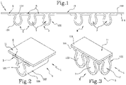
Figure 1 illustrates a detail of a composite web according to the description in a schematic cross sectional view; -
Figure 2 illustrates a detail of a composite web according to the disclosure in a schematic perspective view; -
Figure 3 illustrates a detail of a composite web according to the disclosure in a schematic perspective view; -
Figure 4 illustrates an absorbent article according to the description in a schematic plan view; -
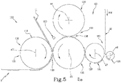
Figure 5 illustrates a unit for forming a composite web according to the description in a schematic front view; -
Figure 6 illustrates a detail of a unit for forming a composite web according to the description in a schematic view; -
Figure 7 illustrates a detail of a unit for forming a composite web according to the description in a schematic view; -
Figure 8 illustrates an absorbent article according to the description in a schematic cross sectional view. - With reference to the accompanying drawings and, in particular,
Figure 1 , thenumeral 1 denotes a composite web according to the description. - The
composite web 1 is preferably intended for the production of absorbent sanitary articles such as nappies, an example of which, labelled 200, is illustrated inFigure 4 . - The
composite web 1, as explained in more detail below, allows making what are known as three-dimensional or 3D topsheets for nappies. - The
composite web 1 comprises a firstcontinuous web 11 and amoulded segment 12S, that is to say, a segment with a pattern M stamped on it. - The moulded
segment 12S is obtained from asegment 12L of a secondcontinuous web 12. Thesegment 12S has afirst face 12A and asecond face 12B. - Basically, the moulded
segment 12S has at least oneprotrusion 4 which is at least partly delimited by abase portion 5, outside theprotrusion 4. - The
protrusion 4 protrudes from thefirst face 12A relative to thebase portion 5. - With reference to the accompanying drawings, the cross section of the
composite web 1 is greatly scaled up in the illustrations so as to make it easier to understand this description. - The moulded
segment 12S defines what is known as the 3D part of the topsheet, made to improve the comfort of the nappy, thanks to theprotrusions 4. - The
segment 12S thus defines a mouldedportion 3 for thecomposite web 1. - The first
continuous web 11 has afirst face 11A and asecond face 11B. - The
first face 11A is joined to thesecond face 12B of thesegment 12S by thebase portions 5. - The
second face 11B is in contact preferably with theabsorbent core 203 of the absorbentsanitary product 200 or with an ADL, if any. Thecomposite web 1 has at least one cavity 7 which is delimited by the mouldedsegment 12S and by theweb 11 at theprotrusions 4. - In other words, the cavity 7 is delimited by the
second face 12B of thesegment 12S at theprotrusion 4 and by thefirst face 11A of the firstcontinuous web 11. - In an embodiment, the
segment 12S, on itsfirst face 12A, has a multiplicity ofprotrusions 4, delimited by a respective multiplicity ofbase portions 5 surrounding theprotrusions 4. - In this embodiment, the
composite web 1 has a multiplicity of cavities 7 delimited by thesegment 12S and by the first continuous web 11 (at the multiplicity of protrusions 4). - The multiplicity of
protrusions 4 defines the motif M, that is, a pattern that will constitute the three-dimensional portion of the topsheet. - The wearer, when wearing an absorbent
sanitary product 200 that comprises thecomposite web 1, is in contact with the protrusions present on thefirst face 12A of thesegment 12S. - Advantageously, the
protrusions 4 improve the comfort for the wearer who is wearing the product and comes into contact with the protrusions. - In an embodiment, the moulded
segment 12S comprises non-woven fabric. - In an embodiment, the moulded
segment 12S comprises polymer fibres. - In an embodiment, the first
continuous web 11 comprises non-woven fabric. - In an embodiment, the first
continuous web 11 is a liquid acquisition and distribution layer (ADL). - The shape imparted to the
segment 12S by moulding is maintained by gluing thesegment 12S to the firstcontinuous web 11. - In an embodiment, the
composite web 1 comprises a discrete succession ofsegments 12S joined to thefirst web 11. - The
composite web 1 has a succession of moulded portions 3 (at thesegments 12S), kept in the required shape by the firstcontinuous web 11. - In an
absorbent article 200 that uses a segment of theweb 1 as topsheet, the segment will have a mouldedportion 3, enhancing the comfort of the wearer, at the mouldedsegment 12S. - In an embodiment, the
protrusions 4 of thesegment 12S have a bubble shape, illustrated, for example, inFigure 3 . - In an embodiment, the
protrusions 4 of thesegment 12S have a wavy shape, illustrated, for example, inFigure 2 . - In an embodiment, the waves moulded on the
segment 12S comprise waves withcrests 4A that are parallel to the main direction of extension of thesegment 12S. - In an embodiment, the waves moulded on the
segment 12S comprise waves withcrests 4A that are transverse to the main direction of extension of thesegment 12S. - The
protrusions 4 may have different shapes: for example, diamond, heart, oval, teardrop, elliptic, shamrock and others. - The
segments 12S and thefirst web 11 are joined, for example, by aweld 9, shown inFigure 1 , and/or by a layer of adhesive 8, illustrated inFigure 2 . - In an embodiment, the
segments 12S and theweb 11 are joined by welding, in particular thermal welding. - In an embodiment, the
segments 12S and theweb 11 are joined by ultrasonic welding. - The layer of adhesive 8 is disposed between the
segment 12S and thecontinuous web 11, preferably between thebase portions 5 that delimit theprotrusions 4 and theweb 11. - This description relates to an absorbent article illustrated, for example, in
Figure 4 and denoted by thereference numeral 200. - The
absorbent article 200, described only insofar as necessary for understanding this invention, essentially comprises: atopsheet 201, animpermeable backsheet 202 and anabsorbent core 203 disposed between thetopsheet 201 and thebacksheet 202. - The
topsheet 201 is the part of thearticle 200 which, in use, is in contact with the wearer. - The
topsheet 201 comprises a segment of acomposite web 1 according to one or more of the features described above. - The
composite web 1 is cut to make a segment of composite web to be assembled in thearticle 200. - The segment of composite web comprises at least one
moulded segment 12S and onesegment 11S of the firstcontinuous web 11. - In an embodiment, the moulded
segment 12S is smaller in length than thesegment 11S. - In an embodiment, the moulded
segment 12S is smaller in width than thesegment 11S. - As illustrated, for example, in
Figure 8 , thesegment 11S included in thecomposite web 1, is disposed between themoulded segment 12S (also included in the composite web 1) and theabsorbent core 203. - In an embodiment, not illustrated, the
absorbent article 200 comprises an ADL (that is, a liquid acquisition and distribution layer) disposed between thesegment 11S and theabsorbent core 203. - Preferably, the ADL is discrete and disposed at the moulded
segment 12S. - Advantageously, the presence of an ADL allows acquiring the liquids and directing them towards an absorbent core, thereby increasing the efficiency of the absorbent
sanitary product 200. - This description relates to a method for the production of a
composite web 1. Thecomposite web 1 is preferably used for making absorbent sanitary articles such as, for example, thearticle 200. - The method essentially comprises the following steps:
- feeding a first
continuous web 11, - feeding at least one
moulded segment 12S of a secondcontinuous web 12, where thesegment 12S has at least oneprotrusion 4 delimited at least partly by abase portion 5, - joining the
segment 12S to thefirst web 11 at thebase portion 5 to delimit at least one cavity 7 between theweb 11 and thesegment 12S at theprotrusions 4. - In an embodiment, the method comprises a step of moulding a
segment 12L of secondcontinuous web 12 to obtain the mouldedsegment 12S. - Preferably, the method, in particular the step of moulding, comprises a step of embossing the
segment 12L, that is, stamping or moulding a 3D pattern on it. - The method used to mould the segment is commonly known as embossing.
- For example, the step of moulding can basically be performed using a first roller that is peripherally provided with a plurality of suction hollows, and a second roller that is peripherally provided with a plurality of teeth that are substantially shaped to match the suction hollows.
- In an embodiment, the method comprises the step of feeding the second
continuous web 12. - In an embodiment the method comprises a step of cutting and spacing the second
continuous web 12 to obtainsegments 12L ofsecond web 12. - The
segments 12L are subsequently moulded to obtainsegments 12S provided withprotrusions 4 delimited bybase portions 5. - The step of cutting and spacing can be carried out, for example, using a method known as slip and cut, that is to say, a method of cutting and sliding whereby (discrete) segments are cut from the web and then spaced apart.
- In an embodiment, the step of joining at least one
moulded segment 12S to the firstcontinuous web 11 comprises a step of welding thesegments 12S to theweb 11 at thebase portion 5. - In an embodiment, the step of welding the
segments 12S to theweb 11 is carried out by ultrasonic welding or thermomechanical welding. In an embodiment, the step of joining thesegments 12S to thecontinuous web 11 comprises a step of disposing a layer of adhesive 8 between thesegments 12S and theweb 11. - Joining the
segments 12S to theweb 11 allows fixing and keeping the 3D pattern imparted to thesegment 12S by moulding. - In an embodiment, a succession of suitably sized and spaced
segments 12S is applied to theweb 11. - In an embodiment, the step of joining the
segment 12S to theweb 11 comprises a step of joining a discrete succession ofsegments 12S to the firstcontinuous web 11. - The first
continuous web 11 is joined at thebase portions 5 of the mouldedsegment 12S, in particular, it is joined on the side opposite theprotrusions 4, defining themoulded portion 3 for thecomposite web 1. - In an embodiment, the method comprises the steps of moulding the
continuous web 12 and cutting and spacing thecontinuous web 12 to obtainsegments 12S. - This description relates to a forming
unit 100 for making composite webs, for example of the type like thecomposite web 1. - The
unit 100 essentially comprises aproduction device 101 and anapplicator device 110. - The
applicator device 110 is configured to join amoulded segment 12S, provided with a pattern M that comprises at least oneprotrusion 4 and onebase portion 5, to a firstcontinuous web 11. - The
production device 101 for making thesegment 12S comprises amoulding device 102 for moulding the pattern M and a cutting andspacing device 103 configured to cut and space a secondcontinuous web 12 to make at least one segment or a plurality ofsegments 12L of the secondcontinuous web 12. - The
device 102 is of a type known in the trade and is also called embossing device. - In an embodiment, the
device 102 is disposed downstream of thedevice 103 in a feed direction V12 of thesecond web 12 so as to mould the pattern M on thesegment 12L. - In an embodiment not illustrated, the
device 102 is disposed upstream of thedevice 103 in the feed direction V12 to mould the pattern M on theweb 12. That way, thesegments 12S that are cut and spaced are already moulded. - The
device 102 comprises afirst drum 104 and asecond drum 105 positioned relative to each other to define a through-gap 106 for passage of thesegment 12L or of theweb 12. - In the example illustrated in
Figure 5 , thefirst drum 104 is rotatable clockwise about an axis a4, while thesecond drum 105 is rotatable anticlockwise about an axis a5, parallel to a4. For simplicity, thedrums - In an embodiment, the
first drum 104 and thesecond drum 105 are provided, respectively, with the male portions and the female portions, which are shaped to match each other and to mould the pattern M (formed of the protrusions 4). - The male - female portions present on the
drums protrusions 4 on thesegment 12S. - The male and female portions are shaped according to the shape which the
protrusion 4 is intended to have. - In an embodiment, the
segment 12S is thus moulded by conveying it between thedrums - The
drums Figure 6 , for example, are shaped to makewavy protrusions 4. - In an embodiment, the
drum 104 is patterned and thedrum 105 acts as anvil. - The
segment 12L advances and passes through thegap 106 so that the outside surfaces of thedrums segment 12L to impart the 3D pattern to it. - The
device 110 is configured to join thesegment 12S to theweb 11 at thebase portion 5. - In an embodiment, the
device 110 is located downstream of theproduction device 101 in a feed direction V12S of the moulded segment. - In an embodiment, as illustrated in the example of
Figure 5 , thedevice 103 comprises ananvil 107, preferably in the form of a drum that is rotatable clockwise about an axis a7, and arotary knife 108 that is rotatable anticlockwise about an axis a8, and acts in conjunction with theanvil 107. - The
knife 108 cuts thecontinuous web 12 to form the segments which are suitably spaced, for example on theanvil 107 itself with a known slip and cut method not further described. - In an embodiment, the
device 103, in particular theanvil 107, is configured to space thesegments 12L. - The
device 110 comprises at least oneapplicator drum 111 that is tangent to thefirst drum 104 or to thesecond drum 105. - The
applicator drum 111 is rotatable about an axis a11 clockwise in the example illustrated inFigure 5 and is located downstream of thedrum 105 in the feed direction V12S. - In an embodiment, the
drum 111 is tangent to thedrum 105 and allows carrying out the step of joining thesegments 12S to theweb 11, that is to say, joining theweb 11 to thebase portions 5 of thesegments 12S, as illustrated schematically inFigure 7 . - In an embodiment, the
device 110 comprises awelder 112 for welding the mouldedsegment 12S to the firstcontinuous web 11. - In an embodiment, the
drum 112 and thedrum 105 are configured to weld thesegments 12S to thefirst web 11. - In an embodiment, the
device 110 comprises anadhesive dispenser 113 located downstream of theproduction device 101 in a feed direction V12S of the moulded segment. Thedispenser 113 dispenses at least one layer of adhesive 8 so that thesegments 12S can be joined to thecontinuous web 11 by the adhesive. For example, thedispenser 113 dispenses the adhesive to theweb 11 and/or to thesegments 12S.
Claims (23)
- A composite web (1) comprising:- a first continuous web (11),- at least one moulded segment (12S) having at least one protrusion (4) and a base portion (5) at least partly delimiting the protrusion (4), the moulded segment (12S) being obtained from a second continuous web (12); the moulded segment (12S) being joined to the first continuous web (11) by the base portion (5), the first continuous web (11) and the moulded segment (12S) delimiting at least one cavity (7) at the protrusion (4).
- The composite web (1) according to claim 1, wherein the moulded segment (12S) comprises a multiplicity of protrusions (4), the protrusions (4) being delimited by a multiplicity of base portions (5), the moulded segment (12S) being joined to the first continuous web (11) by the base portions (5), the first continuous web (11) and the moulded segment (12S) delimiting a multiplicity of cavities (7) at the protrusions (4).
- The composite web (1) according to claim 2, wherein the multiplicity of protrusions (4) defines a pattern (M) on the moulded segment (12S).
- The composite web (1) according to any one of the preceding claims, comprising a multiplicity of moulded segments (12S), the moulded segments (12S) being joined to the first continuous web (11).
- The composite web (1) according to any one of the preceding claims, wherein the moulded segment (12S) comprises a protrusion (4) having a bubble shape.
- The composite web (1) according to any one of the preceding claims, wherein the moulded segment (12S) comprises a protrusion (4) having a wave shape.
- The composite web (1) according to any one of the preceding claims, comprising at least one weld (9), preferably a thermal weld or a thermomechanical weld or an ultrasonic weld, the base portion (5) and the first continuous web (11) being joined by the weld (9).
- The composite web (1) according to any one of the preceding claims, comprising at least one adhesive layer (8), the adhesive layer (8) being disposed between the base portion (5) of the moulded segment (12S) and the first continuous web (11).
- The composite (1) according to any one of the preceding claims, wherein the base portion (5) is outside the protrusion (4).
- An absorbent article (200) comprising:- a topsheet (201),- an impermeable backsheet (202),- an absorbent core (203) disposed between the topsheet (201) and the backsheet (202), wherein the topsheet comprises a segment of a composite web (1) according to any one of the preceding claims, the first continuous web (11) being disposed between the moulded segment (12S) and the absorbent core (203).
- A method for the production of a composite web (1), specifically for making absorbent sanitary articles, comprising the following steps:- feeding a first continuous web (11),- feeding at least one moulded segment (12S) of a second continuous web (12), the moulded segment (12S) having at least one protrusion (4) delimited at least partly by a base portion (5),- joining the moulded segment (12S) to the first continuous web (11) at the base portion (5) to delimit at least one cavity (7) between the first continuous web (11) and the moulded segment (12S) at the protrusion (4).
- The production method according to claim 11, comprising a step of moulding a segment (12L) of the second continuous web (12) to obtain the moulded segment (12S).
- The production method according to claim 12, further comprising the following steps:- feeding the second continuous web (12),- cutting and spacing the second continuous web (12) to obtain the segment (12L) of the second continuous web.
- The production method according to any one of the claims from 11 to 13, wherein the step of joining the moulded segment (12S) to the first continuous web (11) comprises a step of welding the moulded segment (12S) to the first continuous web (11) at least at the base portion (5).
- The production method according to any one of claims 11 to 14, wherein the step of joining the moulded segment (12S) to the first continuous web (11) comprises a step of disposing a layer of adhesive (8) between the moulded segment (12S) and the first continuous web (11).
- The production method according to any one of claims 11 to 15, wherein the step of joining the moulded segment (12S) to the first continuous web (11) comprises a step of joining a discrete succession of moulded segments (12S) to the first continuous web (11).
- A forming unit (100) for making a composite web (1), the forming unit (100) comprising:- an applicator device (110) configured to join a moulded segment (12S), provided with a pattern (M) that comprises at least one protrusion (4), and a base portion (5) to a first continuous web (11);- a production device (101) for making the moulded segment (12S), the production device (101) comprising a moulding device (102) for moulding the pattern (M) and a cutting and spacing device (103) configured to cut and space a second continuous web (12) to make at least one segment (12L) or a plurality of segments (12L) of the second continuous web (12), wherein the moulding device (102) is disposed downstream of the cutting and spacing device (103) in a feed direction (V12) of the second continuous web (12) in order to mould the pattern (M) on the segment (12L) or wherein the moulding device is disposed upstream of the cutting and spacing device (103) in a feed direction of the second continuous web (12) in order to mould the pattern (M) on the second continuous web (12),the moulding device (103) comprising a first drum (104) and a second drum (105) positioned relative to each other to define a through-gap (106) for passage of the segment (12L) of second web or of the second continuous web (12);the applicator device (110) being configured to join the moulded segment (12S) to the first continuous web (11) at the base portion (5), the applicator device (110) being disposed downstream of the production device (101) in a feed direction (V12S) of the moulded segment.
- The forming unit according to claim 17, wherein the cutting and spacing device (103) comprises an anvil (107) and a rotary knife (108) acting in conjunction with the anvil (107).
- The forming unit according to claim 17 or 18, wherein the cutting and spacing device (103), specifically the anvil (107), is configured to space the segments (12L) of second web (12).
- The forming unit according to any one of claims 17 to 19, wherein the applicator device (110) comprises at least one applicator drum (111) that is tangent to the first drum (104) or to the second drum (105).
- The forming unit according to any one of claims 17 to 20, wherein the applicator device (110) comprises a welder (112) for welding the moulded segment (12S) to the first continuous web (11).
- The forming unit according to any one of claims 17 to 21, wherein the applicator device (110) comprises an adhesive dispenser (113), the adhesive dispenser (113) being disposed downstream of the production device (101) in the feed direction (V12S) of the moulded segment.
- The forming unit according to any one of claims 17 to 22, wherein the first drum (104) and the second drum (105) comprise male and female portions, respectively, the male and female portions being shaped to match each other so as to mould the pattern (M) on the moulded segment (12S).
Applications Claiming Priority (2)
| Application Number | Priority Date | Filing Date | Title |
|---|---|---|---|
| IT102021000017159A IT202100017159A1 (en) | 2021-06-30 | 2021-06-30 | COMPOSITE TAPE |
| IT102021000017132A IT202100017132A1 (en) | 2021-06-30 | 2021-06-30 | PRODUCTION METHOD AND FORMING UNIT OF A COMPOSITE TAPE |
Publications (2)
| Publication Number | Publication Date |
|---|---|
| EP4112026A1 true EP4112026A1 (en) | 2023-01-04 |
| EP4112026B1 EP4112026B1 (en) | 2025-12-03 |
Family
ID=82058322
Family Applications (1)
| Application Number | Title | Priority Date | Filing Date |
|---|---|---|---|
| EP22180490.9A Active EP4112026B1 (en) | 2021-06-30 | 2022-06-22 | Composite web |
Country Status (3)
| Country | Link |
|---|---|
| US (1) | US20230000693A1 (en) |
| EP (1) | EP4112026B1 (en) |
| JP (1) | JP2023008910A (en) |
Families Citing this family (2)
| Publication number | Priority date | Publication date | Assignee | Title |
|---|---|---|---|---|
| EP4112025B1 (en) * | 2021-06-30 | 2025-08-27 | Gdm S.P.A. | Composite web |
| CN120380522A (en) | 2022-12-08 | 2025-07-25 | 软银集团股份有限公司 | Information processing apparatus and program |
Citations (11)
| Publication number | Priority date | Publication date | Assignee | Title |
|---|---|---|---|---|
| US5591148A (en) * | 1994-04-08 | 1997-01-07 | The Procter & Gamble Company | Sanitary napkin having an independently displaceable central core segment |
| US8603277B2 (en) * | 2011-03-14 | 2013-12-10 | The Procter & Gamble Company | Method for assembling disposable absorbent articles with an embossed topsheet |
| US20140023822A1 (en) * | 2012-07-18 | 2014-01-23 | Jung-Chi Tai | Shaped sheet laminate, method and apparatus for manufacturing the same |
| WO2014068488A1 (en) * | 2012-10-31 | 2014-05-08 | Kimberly-Clark Worldwide, Inc. | Absorbent article |
| US20150290047A1 (en) * | 2014-04-15 | 2015-10-15 | The Procter Gamble Company | Methods for Inspecting Channel Regions in Absorbent Structures in Absorbent Articles |
| WO2016040091A1 (en) | 2014-09-12 | 2016-03-17 | The Procter & Gamble Company | Process for making an absorbent article comprising a topsheet/acquisition layer laminate |
| US20160075122A1 (en) * | 2014-09-12 | 2016-03-17 | The Procter & Gamble Company | Method Of Making Nonwoven Material Having Discrete Three-Dimensional Deformations With Wide Base Openings That are Tip Bonded to Additional Layer |
| EP3123993A1 (en) * | 2014-03-27 | 2017-02-01 | Daio Paper Corporation | Method for producing absorbent article and absorbent article |
| US20170079857A1 (en) * | 2015-09-22 | 2017-03-23 | The Procter & Gamble Company | Absorbent articles having channels, stretchable waistbands and back ears |
| US9655790B2 (en) * | 2012-05-28 | 2017-05-23 | Daio Paper Corporation | Absorbent article and manufacturing method therefor |
| EP3431063A1 (en) * | 2016-03-16 | 2019-01-23 | Xiamen Yanjan New Material Co., Ltd | Perforated non-woven fabric and procution method therefor |
Family Cites Families (6)
| Publication number | Priority date | Publication date | Assignee | Title |
|---|---|---|---|---|
| US5753343A (en) * | 1992-08-04 | 1998-05-19 | Minnesota Mining And Manufacturing Company | Corrugated nonwoven webs of polymeric microfiber |
| US5951816A (en) * | 1996-03-26 | 1999-09-14 | Marquip, Inc. | Single facer with small intermediate corrugating roll |
| EP2866754B1 (en) * | 2012-06-29 | 2016-07-13 | The Procter & Gamble Company | Method for attaching elastic components to absorbent articles |
| EP3017796B1 (en) * | 2014-11-06 | 2017-11-29 | Fameccanica.Data S.p.A. | A method for producing a backsheet for absorbent sanitary articles and an absorbent sanitary article including this backsheet |
| JP5984156B2 (en) * | 2014-11-19 | 2016-09-06 | 大王製紙株式会社 | Absorbent article manufacturing method and absorbent article |
| WO2021092606A1 (en) * | 2019-11-04 | 2021-05-14 | The Procter & Gamble Company | Method and apparatus for bonding elastic parts under tension to an advancing carrier |
-
2022
- 2022-06-22 EP EP22180490.9A patent/EP4112026B1/en active Active
- 2022-06-29 JP JP2022104173A patent/JP2023008910A/en active Pending
- 2022-06-29 US US17/852,830 patent/US20230000693A1/en active Pending
Patent Citations (11)
| Publication number | Priority date | Publication date | Assignee | Title |
|---|---|---|---|---|
| US5591148A (en) * | 1994-04-08 | 1997-01-07 | The Procter & Gamble Company | Sanitary napkin having an independently displaceable central core segment |
| US8603277B2 (en) * | 2011-03-14 | 2013-12-10 | The Procter & Gamble Company | Method for assembling disposable absorbent articles with an embossed topsheet |
| US9655790B2 (en) * | 2012-05-28 | 2017-05-23 | Daio Paper Corporation | Absorbent article and manufacturing method therefor |
| US20140023822A1 (en) * | 2012-07-18 | 2014-01-23 | Jung-Chi Tai | Shaped sheet laminate, method and apparatus for manufacturing the same |
| WO2014068488A1 (en) * | 2012-10-31 | 2014-05-08 | Kimberly-Clark Worldwide, Inc. | Absorbent article |
| EP3123993A1 (en) * | 2014-03-27 | 2017-02-01 | Daio Paper Corporation | Method for producing absorbent article and absorbent article |
| US20150290047A1 (en) * | 2014-04-15 | 2015-10-15 | The Procter Gamble Company | Methods for Inspecting Channel Regions in Absorbent Structures in Absorbent Articles |
| WO2016040091A1 (en) | 2014-09-12 | 2016-03-17 | The Procter & Gamble Company | Process for making an absorbent article comprising a topsheet/acquisition layer laminate |
| US20160075122A1 (en) * | 2014-09-12 | 2016-03-17 | The Procter & Gamble Company | Method Of Making Nonwoven Material Having Discrete Three-Dimensional Deformations With Wide Base Openings That are Tip Bonded to Additional Layer |
| US20170079857A1 (en) * | 2015-09-22 | 2017-03-23 | The Procter & Gamble Company | Absorbent articles having channels, stretchable waistbands and back ears |
| EP3431063A1 (en) * | 2016-03-16 | 2019-01-23 | Xiamen Yanjan New Material Co., Ltd | Perforated non-woven fabric and procution method therefor |
Also Published As
| Publication number | Publication date |
|---|---|
| US20230000693A1 (en) | 2023-01-05 |
| JP2023008910A (en) | 2023-01-19 |
| EP4112026B1 (en) | 2025-12-03 |
Similar Documents
| Publication | Publication Date | Title |
|---|---|---|
| US5562793A (en) | Methods and apparatus for making multi-layer absorbent products | |
| EP3519162B1 (en) | Apparatus for fabricating an elastic nonwoven material | |
| US7971526B2 (en) | Embossing or bonding device containing facetted impression elements | |
| CN107205861B (en) | Method for deforming a fiber web | |
| CA2079150C (en) | No waste absorbent product | |
| EP4112026A1 (en) | Composite web | |
| CA2221578A1 (en) | Method and apparatus for producing a composite web having transverse stretch | |
| CN107249533B (en) | Method for deforming a fiber web | |
| KR101028264B1 (en) | Absorption pads arranged continuously in the machine-direction with minimal waste | |
| WO2013046653A1 (en) | Fibrous sheet and method for manufacturing the same | |
| EP4112025A1 (en) | Composite web | |
| EP4397288B1 (en) | Split formation of unitary substrates | |
| EP4104806B1 (en) | A three-dimensional tape, an apparatus and a method for the manufacturing thereof | |
| EP2450011A1 (en) | Method for producing bodily fluid-absorbing pad and production device therefor | |
| IT202100017132A1 (en) | PRODUCTION METHOD AND FORMING UNIT OF A COMPOSITE TAPE | |
| IT202100017135A1 (en) | COMPOSITE TAPE | |
| IT202100017159A1 (en) | COMPOSITE TAPE | |
| IT202100017126A1 (en) | METHOD AND UNIT OF PRODUCTION OF A COMPOSITE TAPE | |
| EP2353809A1 (en) | Method and apparatus for producing webs perforated in a through manner and resulting product | |
| US11944525B2 (en) | Absorbent article | |
| HK1012546B (en) | Methods and apparatus for making multi-layer absorbent products |
Legal Events
| Date | Code | Title | Description |
|---|---|---|---|
| PUAI | Public reference made under article 153(3) epc to a published international application that has entered the european phase |
Free format text: ORIGINAL CODE: 0009012 |
|
| STAA | Information on the status of an ep patent application or granted ep patent |
Free format text: STATUS: THE APPLICATION HAS BEEN PUBLISHED |
|
| AK | Designated contracting states |
Kind code of ref document: A1 Designated state(s): AL AT BE BG CH CY CZ DE DK EE ES FI FR GB GR HR HU IE IS IT LI LT LU LV MC MK MT NL NO PL PT RO RS SE SI SK SM TR |
|
| P01 | Opt-out of the competence of the unified patent court (upc) registered |
Effective date: 20230526 |
|
| STAA | Information on the status of an ep patent application or granted ep patent |
Free format text: STATUS: REQUEST FOR EXAMINATION WAS MADE |
|
| 17P | Request for examination filed |
Effective date: 20230704 |
|
| RBV | Designated contracting states (corrected) |
Designated state(s): AL AT BE BG CH CY CZ DE DK EE ES FI FR GB GR HR HU IE IS IT LI LT LU LV MC MK MT NL NO PL PT RO RS SE SI SK SM TR |
|
| STAA | Information on the status of an ep patent application or granted ep patent |
Free format text: STATUS: EXAMINATION IS IN PROGRESS |
|
| 17Q | First examination report despatched |
Effective date: 20240715 |
|
| GRAP | Despatch of communication of intention to grant a patent |
Free format text: ORIGINAL CODE: EPIDOSNIGR1 |
|
| STAA | Information on the status of an ep patent application or granted ep patent |
Free format text: STATUS: GRANT OF PATENT IS INTENDED |
|
| RIN1 | Information on inventor provided before grant (corrected) |
Inventor name: PIANTONI, MATTEO Inventor name: ZAVALLONI, ALESSANDRO |
|
| INTG | Intention to grant announced |
Effective date: 20250709 |
|
| RAP3 | Party data changed (applicant data changed or rights of an application transferred) |
Owner name: GDM S.P.A. |
|
| GRAS | Grant fee paid |
Free format text: ORIGINAL CODE: EPIDOSNIGR3 |
|
| GRAA | (expected) grant |
Free format text: ORIGINAL CODE: 0009210 |
|
| STAA | Information on the status of an ep patent application or granted ep patent |
Free format text: STATUS: THE PATENT HAS BEEN GRANTED |
|
| AK | Designated contracting states |
Kind code of ref document: B1 Designated state(s): AL AT BE BG CH CY CZ DE DK EE ES FI FR GB GR HR HU IE IS IT LI LT LU LV MC MK MT NL NO PL PT RO RS SE SI SK SM TR |
|
| REG | Reference to a national code |
Ref country code: CH Ref legal event code: F10 Free format text: ST27 STATUS EVENT CODE: U-0-0-F10-F00 (AS PROVIDED BY THE NATIONAL OFFICE) Effective date: 20251203 Ref country code: GB Ref legal event code: FG4D |
|
| REG | Reference to a national code |
Ref country code: DE Ref legal event code: R096 Ref document number: 602022025984 Country of ref document: DE |
|
| REG | Reference to a national code |
Ref country code: IE Ref legal event code: FG4D |
|
| REG | Reference to a national code |
Ref country code: NL Ref legal event code: MP Effective date: 20251203 |
|
| PG25 | Lapsed in a contracting state [announced via postgrant information from national office to epo] |
Ref country code: ES Free format text: LAPSE BECAUSE OF FAILURE TO SUBMIT A TRANSLATION OF THE DESCRIPTION OR TO PAY THE FEE WITHIN THE PRESCRIBED TIME-LIMIT Effective date: 20251203 |
|
| REG | Reference to a national code |
Ref country code: LT Ref legal event code: MG9D |
|
| PG25 | Lapsed in a contracting state [announced via postgrant information from national office to epo] |
Ref country code: NO Free format text: LAPSE BECAUSE OF FAILURE TO SUBMIT A TRANSLATION OF THE DESCRIPTION OR TO PAY THE FEE WITHIN THE PRESCRIBED TIME-LIMIT Effective date: 20260303 |
|
| PG25 | Lapsed in a contracting state [announced via postgrant information from national office to epo] |
Ref country code: FI Free format text: LAPSE BECAUSE OF FAILURE TO SUBMIT A TRANSLATION OF THE DESCRIPTION OR TO PAY THE FEE WITHIN THE PRESCRIBED TIME-LIMIT Effective date: 20251203 Ref country code: HR Free format text: LAPSE BECAUSE OF FAILURE TO SUBMIT A TRANSLATION OF THE DESCRIPTION OR TO PAY THE FEE WITHIN THE PRESCRIBED TIME-LIMIT Effective date: 20251203 |
|
| PG25 | Lapsed in a contracting state [announced via postgrant information from national office to epo] |
Ref country code: RS Free format text: LAPSE BECAUSE OF FAILURE TO SUBMIT A TRANSLATION OF THE DESCRIPTION OR TO PAY THE FEE WITHIN THE PRESCRIBED TIME-LIMIT Effective date: 20260303 |
|
| PG25 | Lapsed in a contracting state [announced via postgrant information from national office to epo] |
Ref country code: PL Free format text: LAPSE BECAUSE OF FAILURE TO SUBMIT A TRANSLATION OF THE DESCRIPTION OR TO PAY THE FEE WITHIN THE PRESCRIBED TIME-LIMIT Effective date: 20251203 |
|
| PG25 | Lapsed in a contracting state [announced via postgrant information from national office to epo] |
Ref country code: LV Free format text: LAPSE BECAUSE OF FAILURE TO SUBMIT A TRANSLATION OF THE DESCRIPTION OR TO PAY THE FEE WITHIN THE PRESCRIBED TIME-LIMIT Effective date: 20251203 |