EP4112021A1 - Compression device set and method for attaching device - Google Patents
Compression device set and method for attaching device Download PDFInfo
- Publication number
- EP4112021A1 EP4112021A1 EP21776410.9A EP21776410A EP4112021A1 EP 4112021 A1 EP4112021 A1 EP 4112021A1 EP 21776410 A EP21776410 A EP 21776410A EP 4112021 A1 EP4112021 A1 EP 4112021A1
- Authority
- EP
- European Patent Office
- Prior art keywords
- adhesive sheet
- cover member
- compression
- compression device
- holding body
- Prior art date
- Legal status (The legal status is an assumption and is not a legal conclusion. Google has not performed a legal analysis and makes no representation as to the accuracy of the status listed.)
- Granted
Links
Images










Classifications
-
- A—HUMAN NECESSITIES
- A61—MEDICAL OR VETERINARY SCIENCE; HYGIENE
- A61B—DIAGNOSIS; SURGERY; IDENTIFICATION
- A61B17/00—Surgical instruments, devices or methods
- A61B17/12—Surgical instruments, devices or methods for ligaturing or otherwise compressing tubular parts of the body, e.g. blood vessels or umbilical cord
- A61B17/132—Tourniquets
- A61B17/135—Tourniquets inflatable
-
- A—HUMAN NECESSITIES
- A61—MEDICAL OR VETERINARY SCIENCE; HYGIENE
- A61F—FILTERS IMPLANTABLE INTO BLOOD VESSELS; PROSTHESES; DEVICES PROVIDING PATENCY TO, OR PREVENTING COLLAPSING OF, TUBULAR STRUCTURES OF THE BODY, e.g. STENTS; ORTHOPAEDIC, NURSING OR CONTRACEPTIVE DEVICES; FOMENTATION; TREATMENT OR PROTECTION OF EYES OR EARS; BANDAGES, DRESSINGS OR ABSORBENT PADS; FIRST-AID KITS
- A61F13/00—Bandages or dressings; Absorbent pads
- A61F13/02—Adhesive bandages or dressings
- A61F13/023—Adhesive bandages or dressings wound covering film layers without a fluid retention layer
- A61F13/0236—Adhesive bandages or dressings wound covering film layers without a fluid retention layer characterised by the application/handling support layer
- A61F13/024—Adhesive bandages or dressings wound covering film layers without a fluid retention layer characterised by the application/handling support layer the application or handling support layer being removable
-
- A—HUMAN NECESSITIES
- A61—MEDICAL OR VETERINARY SCIENCE; HYGIENE
- A61F—FILTERS IMPLANTABLE INTO BLOOD VESSELS; PROSTHESES; DEVICES PROVIDING PATENCY TO, OR PREVENTING COLLAPSING OF, TUBULAR STRUCTURES OF THE BODY, e.g. STENTS; ORTHOPAEDIC, NURSING OR CONTRACEPTIVE DEVICES; FOMENTATION; TREATMENT OR PROTECTION OF EYES OR EARS; BANDAGES, DRESSINGS OR ABSORBENT PADS; FIRST-AID KITS
- A61F13/00—Bandages or dressings; Absorbent pads
- A61F13/02—Adhesive bandages or dressings
- A61F13/0246—Adhesive bandages or dressings characterised by the skin-adhering layer
-
- A—HUMAN NECESSITIES
- A61—MEDICAL OR VETERINARY SCIENCE; HYGIENE
- A61M—DEVICES FOR INTRODUCING MEDIA INTO, OR ONTO, THE BODY; DEVICES FOR TRANSDUCING BODY MEDIA OR FOR TAKING MEDIA FROM THE BODY; DEVICES FOR PRODUCING OR ENDING SLEEP OR STUPOR
- A61M25/00—Catheters; Hollow probes
- A61M25/01—Introducing, guiding, advancing, emplacing or holding catheters
- A61M25/02—Holding devices, e.g. on the body
-
- A—HUMAN NECESSITIES
- A61—MEDICAL OR VETERINARY SCIENCE; HYGIENE
- A61B—DIAGNOSIS; SURGERY; IDENTIFICATION
- A61B17/00—Surgical instruments, devices or methods
- A61B2017/00831—Material properties
- A61B2017/00951—Material properties adhesive
-
- A—HUMAN NECESSITIES
- A61—MEDICAL OR VETERINARY SCIENCE; HYGIENE
- A61F—FILTERS IMPLANTABLE INTO BLOOD VESSELS; PROSTHESES; DEVICES PROVIDING PATENCY TO, OR PREVENTING COLLAPSING OF, TUBULAR STRUCTURES OF THE BODY, e.g. STENTS; ORTHOPAEDIC, NURSING OR CONTRACEPTIVE DEVICES; FOMENTATION; TREATMENT OR PROTECTION OF EYES OR EARS; BANDAGES, DRESSINGS OR ABSORBENT PADS; FIRST-AID KITS
- A61F13/00—Bandages or dressings; Absorbent pads
- A61F2013/00361—Plasters
- A61F2013/00365—Plasters use
- A61F2013/00412—Plasters use for use with needles, tubes or catheters
-
- A—HUMAN NECESSITIES
- A61—MEDICAL OR VETERINARY SCIENCE; HYGIENE
- A61F—FILTERS IMPLANTABLE INTO BLOOD VESSELS; PROSTHESES; DEVICES PROVIDING PATENCY TO, OR PREVENTING COLLAPSING OF, TUBULAR STRUCTURES OF THE BODY, e.g. STENTS; ORTHOPAEDIC, NURSING OR CONTRACEPTIVE DEVICES; FOMENTATION; TREATMENT OR PROTECTION OF EYES OR EARS; BANDAGES, DRESSINGS OR ABSORBENT PADS; FIRST-AID KITS
- A61F13/00—Bandages or dressings; Absorbent pads
- A61F2013/00361—Plasters
- A61F2013/00365—Plasters use
- A61F2013/00463—Plasters use haemostatic
- A61F2013/00468—Plasters use haemostatic applying local pressure
-
- A—HUMAN NECESSITIES
- A61—MEDICAL OR VETERINARY SCIENCE; HYGIENE
- A61M—DEVICES FOR INTRODUCING MEDIA INTO, OR ONTO, THE BODY; DEVICES FOR TRANSDUCING BODY MEDIA OR FOR TAKING MEDIA FROM THE BODY; DEVICES FOR PRODUCING OR ENDING SLEEP OR STUPOR
- A61M25/00—Catheters; Hollow probes
- A61M25/01—Introducing, guiding, advancing, emplacing or holding catheters
- A61M25/02—Holding devices, e.g. on the body
- A61M2025/0246—Holding devices, e.g. on the body fixed on the skin having a cover for covering the holding means
-
- A—HUMAN NECESSITIES
- A61—MEDICAL OR VETERINARY SCIENCE; HYGIENE
- A61M—DEVICES FOR INTRODUCING MEDIA INTO, OR ONTO, THE BODY; DEVICES FOR TRANSDUCING BODY MEDIA OR FOR TAKING MEDIA FROM THE BODY; DEVICES FOR PRODUCING OR ENDING SLEEP OR STUPOR
- A61M25/00—Catheters; Hollow probes
- A61M25/01—Introducing, guiding, advancing, emplacing or holding catheters
- A61M25/02—Holding devices, e.g. on the body
- A61M2025/0266—Holding devices, e.g. on the body using pads, patches, tapes or the like
-
- A—HUMAN NECESSITIES
- A61—MEDICAL OR VETERINARY SCIENCE; HYGIENE
- A61M—DEVICES FOR INTRODUCING MEDIA INTO, OR ONTO, THE BODY; DEVICES FOR TRANSDUCING BODY MEDIA OR FOR TAKING MEDIA FROM THE BODY; DEVICES FOR PRODUCING OR ENDING SLEEP OR STUPOR
- A61M25/00—Catheters; Hollow probes
- A61M25/01—Introducing, guiding, advancing, emplacing or holding catheters
- A61M25/02—Holding devices, e.g. on the body
- A61M2025/028—Holding devices, e.g. on the body having a mainly rigid support structure
Definitions
- This disclosure generally relates to a compression device set and a method for attaching a device.
- catheters In recent years, in medical institutions, various forms of examinations or treatments are performed using elongated hollow tubular medical devices called catheters.
- a catheter is percutaneously inserted into a blood vessel from a puncture site formed at a wrist, an inguinal region, and the like, and is carried through the blood vessel to a site to be examined or treated. After an examination or treatment by a health care worker is completed, the catheter, or a sheath used to introduce the catheter, is removed from the puncture site, and the puncture site is stopped from bleeding.
- Patent document 1 discloses a compression device that compresses a wound of a patient or its vicinity after a sheath is removed.
- the compression device disclosed in the patent document 1 includes an adhesive sheet having an adhesion surface and a compression member attached to the adhesive sheet.
- the disclosed adhesive sheet in the patent document 1 includes a first portion to which a fixing portion of the compression member is fixed, and a second portion to which the fixing portion of the compression member is not fixed.
- Patent document 1 WO 2019/221201
- the compression device disclosed in the patent document 1 is unlikely to be released from a biological surface, since the adhesive sheet includes the second portion.
- the second portion of the adhesive sheet includes a portion that is not covered by the compression member. Therefore, when the compression device is attached to the biological surface, the portion of the second portion of the adhesive sheet which is not covered by the compression member is unlikely to be pressed against the biological surface. That is, in the compression device disclosed in the patent document 1, there is still room for improvement from a viewpoint of operability when the second portion of the adhesive sheet is adhered to the biological surface.
- a compression device set and a method for attaching a device that are capable of implementing a compression device that is easily attached to a biological surface and that is unlikely to be released from the biological surface.
- a compression device set includes: a compression device that is configured to be adhered to a biological surface and that is configured to compress the biological surface; and a cover member configured to be attached to and detached from the compression device.
- the compression device includes: an adhesive sheet having, on a lower surface, an adhesion surface configured to be adhered to the biological surface; and a compression member that is fixed to the adhesive sheet on an upper surface side of the adhesive sheet and that is configured to compress the biological surface in a state in which the adhesion surface of the adhesive sheet is adhered to the biological surface.
- the adhesive sheet includes a first portion that is in contact with the compression member and a second portion that is not in contact with the compression member.
- the cover member is configured to be attached to the compression member in a state in which the cover member is configured to come into contact with an upper surface of at least a part of the second portion of the adhesive sheet.
- the compression member of the compression device includes: an expander that is expandable; and a holding body configured to hold the expander to be expandable in a sheet thickness direction of the adhesive sheet, and the cover member is configured to be attached to the holding body.
- the second portion of the adhesive sheet includes a peripheral portion located outside an outer edge of the holding body in a plan view seen in the sheet thickness direction, and the cover member is configured to be attached to the holding body in a state in which the cover member is configured to come into contact with an upper surface of the entire peripheral portion.
- the cover member is locked to the holding body by engaging with a side end surface of the holding body, the side end surface being located in a sheet in-plane direction orthogonal to the sheet thickness direction.
- the cover member includes: a clamping portion configured to clamp opposite portions of the side end surface of the holding body; and a sheet cover portion that protrudes from the clamping portion in the sheet in-plane direction and that is configured to come into contact with the upper surface of at least a part of the second portion of the adhesive sheet in the state in which the clamping portion clamps the opposite portions of the side end surface of the holding body.
- the cover member includes a pair of gripping portions extending from the clamping portion in the sheet thickness direction, and by changing a facing distance between the pair of gripping portions, the cover member is switchable between a locking position at which the clamping portion clamps the opposite portions of the side end surface of the holding body and a locking release position at which the clamping portion does not clamp the opposite portions of the side end surface of the holding body.
- the cover member includes: a side-end engaging portion that engages with each of the opposite portions of the side end surface of the holding body; and a sheet cover portion that protrudes from the side-end engaging portion in the sheet in-plane direction and that is configured to come into contact with the upper surface of at least a part of the second portion of the adhesive sheet in the state in which the side-end engaging portion engages with the opposite portions of the side end surface of the holding body, one of the side-end engaging portion and the opposite portions of the side end surface of the holding body is provided with a convex portion, and the other one of the side-end engaging portion and the opposite portions of the side end surface of the holding body is provided with a concave portion or a hole portion that is fitted with the convex portion.
- the cover member includes a pair of gripping portions each extending in the sheet thickness direction from the side-end engaging portion, and by changing a facing distance between the pair of gripping portions, the cover member is switchable between a locking position at which the convex portion is fitted into the concave portions or the hole portions and a locking release position at which the convex portion is not fitted into the concave portion or the hole portion.
- a method for attaching a compression device to a biological surface is configured to be adhered to the biological surface and is configured to compress the biological surface.
- the compression device includes: an adhesive sheet having, on a lower surface, an adhesion surface configured to be adhered to the biological surface; and a compression member that is fixed to the adhesive sheet on an upper surface side of the adhesive sheet and that is configured to compress the biological surface in a state in which the adhesion surface of the adhesive sheet is adhered to the biological surface, the adhesive sheet includes a first portion that is in contact with the compression member and a second portion that is not in contact with the compression member.
- the method includes: an attaching step of attaching a cover member to the compression member in a state in which the cover member is configured to come into contact with an upper surface of at least a part of the second portion of the adhesive sheet; and an adhering step of pressing at least a part of the second portion of the adhesive sheet toward the biological surface via the cover member, and adhering at least the part of the second portion to the biological surface.
- the compression device set and the method for attaching the device that are capable of implementing the compression device that is easy to be attached to the biological surface and that is unlikely to be released from the biological surface.
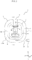
- Fig. 1 is a view showing a compression device set 1000 according to one embodiment of the compression device set according to this disclosure.
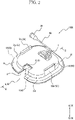
- the compression device set 1000 includes a compression device 1 and a cover member 51.
- the cover member 51 can be attached to and detached from the compression device 1.
- Fig. 1 shows the compression device set 1000 in a state in which the cover member 51 is not attached to the compression device 1.
- Fig. 2 shows the compression device set 1000 in a state in which the cover member 51 is detachably attached to the compression device 1.
- Figs. 1 and 2 show the compression device 1 in a state in which a release sheet 4 is attached to an adhesion surface 11 of an adhesive sheet 2. The release sheet 4 is released when the compression device 1 is attached to a biological surface.
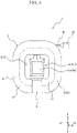
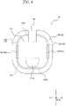
- Figs. 3 and 4 are plan views of the compression device 1. Specifically, Fig. 3 is a top view of the compression device 1. Fig. 4 is a bottom view of the compression device 1. Figs. 5 and 6 are section views of the compression device 1 in a cross section taken along the section line V-V and VI-Vi respectively in Fig. 3 . The details will be described later, and Figs. 5 and 6 show different states of the compression device 1. In addition, Figs. 3 to 6 show the compression device 1 in a state in which the release sheet 4 (see Fig. 1 or the like) is removed.
- the compression device 1 can be adhered to the biological surface.
- the compression device 1 can compress the biological surface in a state of being adhered to the biological surface.
- the compression device 1 includes the adhesive sheet 2 and a compression member 3.
- the adhesive sheet 2 has, on a lower surface, the adhesion surface 11 that can be adhered to the biological surface.
- the compression member 3 is fixed to the adhesive sheet 2 on an upper surface side of the adhesive sheet 2. In addition, the compression member 3 can compress the biological surface in a state in which the adhesion surface 11 of the adhesive sheet 2 is adhered to the biological surface.
- the compression device 1 is fixed to a position on the biological surface by adhering the adhesion surface 11 of the adhesive sheet 2 to the biological surface.
- the compression device 1 can compress a predetermined site on the biological surface by the compression member 3 in a state in which the compression device 1 is fixed to the position on the biological surface by the adhesion surface 11 of the adhesive sheet 2.
- a predetermined site on the biological surface includes, for example, a wound on the biological surface or its vicinity formed by inserting an elongated medical device such as a puncture needle, a catheter, and a sheath, from the biological surface, into a blood vessel of a living body. After the medical device is removed from the living body, bleeding can be stopped by compressing the wound on the biological surface or its vicinity by the compression member 3.
- the adhesive sheet 2 has the adhesion surface 11 on the lower surface located on one side in a sheet thickness direction A.
- the adhesive sheet 2 has, on an upper surface located on the other side in the sheet thickness direction A, an attaching surface 12 to which the compression member 3 is attached.
- the adhesive sheet 2 has flexibility. Therefore, the adhesive sheet 2 can be deformed according to a shape of the biological surface.
- the adhesion surface 11 easily follows deformation of the biological surface. As a result, it is possible to prevent the compression device 1 from being unintentionally released from the biological surface.
- the one side in the sheet thickness direction A which is a direction from the attaching surface 12 to the adhesion surface 11 in the sheet thickness direction A
- the other side in the sheet thickness direction A which is a direction from the adhesion surface 11 to the attaching surface 12 in the sheet thickness direction A
- a plan view (see Figs. 3 and 4 ) of the compression device 1 seen along the sheet thickness direction A of the adhesive sheet 2 a plan view (see Fig.
- a plan view (see Fig. 4 ) of the compression device 1 seen from an attaching surface 12 side of the adhesive sheet 2 may be simply referred to as a "top view” for convenience of description.
- a plan view (see Fig. 4 ) of the compression device 1 seen from an adhesion surface 11 side of the adhesive sheet 2 may be simply referred to as a "bottom view” for convenience of description.
- the "plan view” is simply referred to.
- the simple descriptions of the "plan view”, the “top view”, and the “bottom view” mean a plan view, a top view, and a bottom view when an expander 21 of the compression member 3 to be described later is in a retracted form.
- the adhesive sheet 2 includes a plurality of layers including, for example, a base material layer and an adhesive layer.
- the base material layer is formed of, for example, a thin resin sheet. More specifically, the base material layer is formed of, for example, a white spunlace nonwoven fabric of polyester fibers, and has a thickness in a range of 5 ⁇ m to 150 ⁇ m, and for example, 30 ⁇ m.
- a material of the base material layer is not limited to polyester, and an acrylic polymer, polyethylene, an ethylene-vinyl acetate copolymer, polyurethane, a polyamide derivative, and the like may be used.
- the adhesive layer is formed of an adhesive such as a rubber-based adhesive, an acrylic-based adhesive, and a silicon-based adhesive, for example.
- the adhesive layer is stacked on the base material layer directly or indirectly with another layer interposed therebetween.
- the adhesion surface 11 of the adhesive sheet 2 according to the present embodiment is an adhesive layer.
- the adhesive sheet 2 may further include another layer in addition to the above-mentioned base material layer and the adhesive layer.
- the adhesive sheet 2 may include, for example, a surface layer.
- the surface layer is formed of, for example, a resin having a thickness of about 5 ⁇ m to 50 ⁇ m. More specifically, examples of a material of the surface layer include polyester, polyamide, polyamideimide, polyethylene, polypropylene, polycarbonate, polyurethane, polyvinyl chloride, and fluororesin.
- the surface layer is stacked on the base material layer directly or indirectly with another layer interposed therebetween on a side opposite to the adhesive layer with the base material layer interposed therebetween. Therefore, the attaching surface 12 of the adhesive sheet 2 may be a surface layer.
- the adhesive sheet 2 may be formed of, for example, a nonwoven fabric tape having an adhesive agent as an adhesive on one surface thereof.
- the adhesive sheet 2 may be formed of, for example, a double-sided tape in which adhesive layers are provided on both sides of the base material layer.
- the compression member 3 can be fixed to the adhesive sheet 2 by being adhered to one adhesive layer of the adhesive sheet 2.
- the adhesive sheet 2 according to the present embodiment extends in a C shape in the plan view shown in Figs. 3 and 4 .
- the adhesive sheet 2 according to the present embodiment defines a central opening region in the plan view.
- a receiving portion 6 to be described later constitutes an open region communicating with the outside.
- the open region in the central opening region is a gap region sandwiched between both end portions of the C-shaped adhesive sheet 2 in the plan view.
- the adhesive sheet 2 extends in the C shape in the plan view, but is not limited to the shape.
- the adhesive sheet 2 may have, for example, an endless outer shape in the plan view.
- An outer edge shape and an inner edge shape of the endless adhesive sheet in the plan view are not particularly limited.
- the outer edge shape and the inner edge shape of the adhesive sheet having the endless outer shape in the plan view can be various shapes such as a circular shape, an oval shape, and a polygonal shape including a square shape.
- a slit extending from an outer edge to an inner edge is formed.
- the central opening region and the outside communicate with each other through the slit. Therefore, a medical device such as a catheter and a sheath can be moved from the outside of the adhesive sheet into the central opening region through the slit.
- the adhesive sheet 2 includes the first portion X1 that comes into contact with the compression member 3 and the second portion X2 that does not come into contact with the compression member 3.
- the first portion X1 means a region of the adhesive sheet 2 in a sheet in-plane direction B in which the compression member 3 comes into contact with the upper surface side.
- the second portion X2 means a region of the adhesive sheet 2 in the sheet in-plane direction B in which the compression member 3 does not come into contact with the upper surface side. Therefore, for example, if a portion is covered with the compression member 3 on the upper surface side and comes into contact with the compression member 3, the portion corresponds to the first portion X1 regardless of whether the compression member 3 is fixed.
- the adhesion surface 11 is provided in at least a part of a region of a lower surface of the first portion X1 and at least a part of a region of a lower surface of the second portion X2. More specifically, the adhesion surface 11 according to the present embodiment is provided on the entire lower surface of the first portion X1 and the entire lower surface of the second portion X2. That is, the adhesion surface 11 according to the present embodiment is provided on the entire lower surface of the adhesive sheet 2. Since the adhesive sheet 2 of the compression device 1 includes the second portion X2, it is possible to prevent the adhesive sheet 2 from being unintentionally released from the biological surface. The effect is based on the same principle as that described in the patent document 1.
- the adhesive sheet 2 according to the present embodiment includes a peripheral portion 13 located on an outer periphery of the compression member 3 in the plan view.
- the peripheral portion 13 of the adhesive sheet 2 according to the present embodiment is the second portion X2 that does not come into contact with the compression member 3.
- the second portion X2 of the adhesive sheet 2 includes the peripheral portion 13 located outside an outer edge of a holding body 22, which will be described later, of the compression member 3 in the plan view.
- the peripheral portion 13 of the adhesive sheet 2 does not surround the entire periphery of the compression member 3 in the plan view. That is, there is a position at which the peripheral portion 13 of the adhesive sheet 2 is not provided in the periphery of the compression member 3. At the position at which the peripheral portion 13 of the adhesive sheet 2 is not provided, a portion of the medical device such as a sheath inserted into the living body that extends outside the living body is received. That is, the receiving portion 6 that can receive the medical device such as a sheath is defined at the position at which the peripheral portion 13 of the adhesive sheet 2 is not provided in the periphery of the compression member 3.
- the compression device 1 can be attached to the biological surface in a state in which the portion of the medical device such as a sheath whose distal end side is inserted into the living body which extends outside the living body is received by the receiving portion 6. Therefore, even in a state in which the medical device such as a sheath is inserted into the living body, it is easy to dispose the expander 21, which will be described later, of the compression member 3 such that the wound on the biological surface formed by the medical device or its vicinity is covered. That is, in such an arrangement state, the compression device 1 can be easily attached to the biological surface.
- the wound on the biological surface or its vicinity is easily compressed by the expander 21 of the compression member 3 of the compression device 1.
- the compression member 3 is fixed to the adhesive sheet 2 on the upper surface side of the adhesive sheet 2.
- the compression member 3 according to the present embodiment is fixed to the attaching surface 12 of the adhesive sheet 2.
- the compression member 3 can compress the biological surface in a state in which the adhesion surface 11 of the adhesive sheet 2 is adhered to the biological surface.
- the compression member 3 according to the present embodiment includes the expander 21 that is expandable and the holding body 22 that holds the expander 21 to be expandable in the sheet thickness direction A of the adhesive sheet 2.
- the holding body 22 of the compression member 3 according to the present embodiment includes a portion that overlaps with the adhesive sheet 2 and a portion that does not overlap with the adhesive sheet 2 in the plan view. More specifically, the holding body 22 of the compression member 3 according to the present embodiment covers the central opening region of the adhesive sheet 2 in the plan view. A portion of the holding body 22 that overlaps with the central opening region in the plan view is the portion that does not overlap with the adhesive sheet 2. The holding body 22 according to the present embodiment covers the central opening region, and an outer edge portion of the holding body 22 in the plan view overlaps with the adhesive sheet 2.
- the portion of the holding body 22 that overlaps with the adhesive sheet 2 in the plan view is in contact with and fixed to the attaching surface 12 of the adhesive sheet 2.
- the entire region of the portion of the holding body 22 that overlaps with the adhesive sheet 2 in the plan view may not be in contact with and fixed to the attaching surface 12 of the adhesive sheet 2. Therefore, only a small portion of the portion of the holding body 22 that overlaps with the adhesive sheet 2 in the plan view may be in contact with and fixed to the attaching surface 12 of the adhesive sheet 2. Therefore, the portion of the holding body 22 that overlaps with the adhesive sheet 2 in the plan view may include, for example, a portion that comes into contact with the attaching surface 12 of the adhesive sheet 2 but is not fixed thereto.
- the expander 21 according to the present embodiment, which will be described later, expands toward the downward direction A1 in the central opening region defined by the adhesive sheet 2 and can compress the biological surface.
- the holding body 22 has a rounded square shape in the plan view and has a flat outer shape in the sheet thickness direction A.
- the holding body 22 covers a first inflatable portion 41a and a second inflatable portion 41b of an inflatable body 40 to be described later as the expander 21 in the upward direction A2.
- the holding body 22 is formed with a through hole 22a through which an extending portion 42 of the inflatable body 40 to be described later is inserted.
- a locking protrusion 22c to which the extending portion 42 of the inflatable body 40 to be described later is locked is provided on an upper surface of the holding body 22.
- Examples of a material of the holding body 22 include a resin material.
- the resin material include thermoplastic resins used in injection molding such as ABS resin, AS resin, polyethylene, polypropylene, polystyrene, polyvinyl chloride, polyvinylidene chloride resin, polyphenylene oxide, thermoplastic polyurethane, polymethylene methacrylate, polyoxyethylene, fluororesin, polycarbonate, polyamide, acetal resin, acrylic resin, and polyethylene terephthalate, and thermosetting resins such as phenol resin, epoxy resin, silicone resin, and unsaturated polyester.
- thermoplastic resins used in injection molding such as ABS resin, AS resin, polyethylene, polypropylene, polystyrene, polyvinyl chloride, polyvinylidene chloride resin, polyphenylene oxide, thermoplastic polyurethane, polymethylene methacrylate, polyoxyethylene, fluororesin, polycarbonate, polyamide, acetal resin, acrylic resin, and polyethylene terephthalate
- the expander 21 is held by the holding body 22.
- the expander 21 can protrude from the adhesion surface 11 of the adhesive sheet 2 toward the downward direction A1 as the one side in the sheet thickness direction A.
- the expander 21 protrudes in the downward direction A1 from the adhesion surface 11 of the adhesive sheet 2 in a state in which the adhesion surface 11 of the adhesive sheet 2 is adhered to the biological surface. Accordingly, the biological surface is compressed by the expander 21.
- the expander 21 according to the present embodiment is the inflatable body 40 that can be inflated toward the downward direction A1 of the sheet thickness direction A by supplying a fluid such as air to the inflatable body 40.
- a fluid such as air
- the inflatable body 40 according to the present embodiment is changed in form from a retracted form which is deflated as shown in Fig. 5 to a protruding form which is inflated as shown in Fig. 6 , the inflatable body 40 protrudes toward the downward direction A1 from the adhesion surface 11 of the adhesive sheet 2 in the sheet thickness direction A, and is in a posture capable of compressing the biological surface.
- the compression device 1 according to the present embodiment is adhered to the biological surface in the retracted form (see Fig. 5 ) before the inflatable body 40 as the expander 21 is inflated.
- the inflatable body 40 is inflated by an operation of an operator such as a health care worker in a state in which the compression device 1 is fixed to the biological surface.
- the inflatable body 40 is inflated into the protruding form (see Fig. 6 ).
- the compression device 1 according to the present embodiment can compress the predetermined site on the biological surface by changing the inflatable body 40 from the retracted form to the protruding form.
- the predetermined site on the biological surface is a wound or the like formed by inserting a medical device such as a sheath into the living body.
- the inflatable body 40 as the expander 21 according to the present embodiment is substantially flush with the adhesion surface 11 of the adhesive sheet 2 in the retracted form, and does not protrude from the adhesion surface 11 in the downward direction A1.
- the holding body 22 may include a locking mechanism that locks the inflatable body 40 so that the inflatable body 40 does not protrude beyond the adhesion surface 11 of the adhesive sheet 2 in the downward direction A1 in the retracted form.
- the inflatable body 40 defines internal spaces 40a.
- the internal spaces 40a of the inflatable body 40 communicate with a tube 28 that penetrates the holding body 22 and extends to the outside of the holding body 22.
- a fluid such as air is supplied through the tube 28 to the internal spaces 40a of the inflatable body 40 from a fluid supply device such as a syringe connected to an inflation port as a connection portion 29 provided at an end portion of the tube 28.
- the inflatable body 40 can be changed from the retracted form (see Fig. 5 ) to the protruding form (see Fig. 6 ). That is, the inflatable body 40 as the expander 21 can protrude from the adhesion surface 11 of the adhesive sheet 2 in the downward direction A1.
- the fluid supplied to the internal spaces of the inflatable body 40 is not limited to gas, and may be a liquid.
- the inflatable body 40 can also be changed from the protruding form (see Fig. 6 ) to the retracted form (see Fig. 5 ).
- the expander 21 includes a contact portion 21a that comes into contact with the biological surface and directly compresses the biological surface, and a pressing portion 21b that presses the contact portion 21a in a predetermined direction to increase a compression force of the contact portion 21a in the predetermined direction.
- the inflatable body 40 as the expander 21 according to the present embodiment includes the first inflatable portion 41a as the contact portion 21a and the second inflatable portion 41b as the pressing portion 21b.
- the first inflatable portion 41a defines a first internal space 41a1.
- the second inflatable portion 41b defines a second internal space 41b1.
- the first internal space 41a1 and the second internal space 41 b1 communicate with each other.
- the first inflatable portion 41a in the deflated state is located on a lower side, and the second inflatable portion 41b in the deflated state is overlapped on an upper side.
- the second inflatable portion 41b is covered with the holding body 22 in the upward direction A2.
- the first inflatable portion 41 a and the second inflatable portion 41b are continuous only on one end side (left side in Fig. 6 ) in the sheet in-plane direction B orthogonal to the sheet thickness direction A.
- the fluid supplied to the internal spaces 40a of the inflatable body 40 through the tube 28 flows into the second internal space 41b1 of the second inflatable portion 41b, and then flows into the first internal space 41a1 of the first inflatable portion 41a. Therefore, when the fluid is supplied to the internal spaces 40a of the inflatable body 40, the second inflatable portion 41b is first inflated. As described above, since the second inflatable portion 41b is covered by the holding body 22 in the upward direction A2, the second inflatable portion 41 b to which the fluid is supplied is inflated in the downward direction A1. Next, the fluid flows into the first internal space 41a1 and the first inflatable portion 41a is inflated. At this time, the first inflatable portion 41a is inflated while pivoting about the one end side (left side in Fig.
- the inflatable body 40 includes a sheet-shaped extending portion 42 extending from the first inflatable portion 41a and the second inflatable portion 41b.
- the first inflatable portion 41a and the second inflatable portion 41b according to the present embodiment are continuous with the extending portion 42 on a receiving portion 6 side in the sheet in-plane direction B in a cross-sectional view in Figs. 5 and 6 .
- the first inflatable portion 41a and the second inflatable portion 41b pivot about a portion of the extending portion 42 connected to the first inflatable portion 41a and the second inflatable portion 41b as a hinge portion.
- the first inflatable portion 41a and the second inflatable portion 41b can be inflated not only toward the sheet thickness direction A but also toward a direction inclined with respect to the sheet thickness direction A.
- the sheet-shaped extending portion 42 extending from a lower surface side to an upper surface side of the holding body 22 through the through hole 22a of the holding body 22 is fixed to the holding body 22 on the upper surface side of the holding body 22. Accordingly, the inflatable body 40 according to the present embodiment is locked to the holding body 22. More specifically, a slit is formed in the extending portion 42 according to the present embodiment. The locking protrusion 22c provided on the upper surface of the holding body 22 is inserted into the slit. Accordingly, the extending portion 42 is positioned on the holding body 22.
- each of the first inflatable portion 41a and the second inflatable portion 41b according to the present embodiment is constituted by a balloon portion.
- the two balloon portions overlap with each other in the sheet thickness direction A.
- one end of each of the two balloon portions is attached to the extending portion 42. That is, the one end side of each of the two balloon portions is restrained by the extending portion 42. Therefore, even when the two balloon portions are inflated, the two balloon portions are not separated from each other on the one end side.
- the other end side of each of the two balloon portions is not restrained at all. Therefore, when the two balloon portions are inflated, the two balloon portions are separated from each other on the other end side.
- the first inflatable portion 41a and the second inflatable portion 41b according to the present embodiment are inflated toward the direction inclined with respect to the sheet thickness direction A.
- Perforations P see Fig. 13B
- the details will be described later (see Fig. 14 ).
- the configuration for inflating the inflatable body 40 toward the direction inclined with respect to the sheet thickness direction A is not limited to a configuration of the expander 21 according to the present embodiment.
- Materials that may be used to fabricatethe balloon portions constituting the first inflatable portion 41a and the second inflatable portion 41b include, for example, soft polyvinyl chloride, polyurethane, polyethylene, polypropylene, polyester, ethylene-vinyl acetate copolymer (EVA), silicone, or a material having flexibility obtained by mixing any of these materials.
- the configuration of the expander 21 is not particularly limited.
- the expander 21 may not have the pressing portion 21b.
- the expander 21 may not be an inflatable body. Further, even when the expander 21 is an inflatable body, the expander 21 is not limited to the configuration of the inflatable body 40.
- Fig. 7 is a perspective view of the cover member 51 seen from a lower side.
- Fig. 8 is a top view of the cover member 51.
- Fig. 9 is a bottom view of the cover member 51.
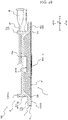
- Fig. 10 is a section view of the compression device set 1000 in a state in which the cover member 51 is attached to the compression device 1. Specifically, Fig. 10 is a section view taken along a line X-X in Fig. 2 .
- the cover member 51 can be attached to the compression member 3.
- the cover member 51 can be attached to the compression member 3 in a state in which the cover member 51 comes into contact with an upper surface of at least a part of the second portion X2 of the adhesive sheet 2. Therefore, when the compression device 1 is pressed against the biological surface in a state in which the cover member 51 is attached to the compression device 1, the second portion X2 of the adhesive sheet 2 can be pressed toward the biological surface by the cover member 51. Accordingly, the adhesion surface 11 provided on the lower surface of the second portion X2 of the adhesive sheet 2 is also easily adhered to the biological surface.
- the second portion X2 of the adhesive sheet 2 which is unlikely to be released from the biological surface after being adhered, is easily adhered to the biological surface.
- the compression device set 1000 it is possible to implement the compression device 1 that is easily attached to the biological surface and that is unlikely to be released from the biological surface.
- the cover member 51 may be attached to the compression member 3 in a state in which the cover member 51 may come into contact with the upper surface of at least a part of the second portion X2 of the adhesive sheet 2. That is, in a state in which the cover member 51 is attached to the compression member 3, the cover member 51 may not be in constant contact with the upper surface of at least a part of the second portion X2 of the adhesive sheet 2. In such a case, the cover member 51 may come into contact with the upper surface of at least a part of the second portion X2 of the adhesive sheet 2.
- a part of the cover member 51 (for example, a flange plate portion 51c as a sheet cover portion 53 to be described later according to the present embodiment) can be elastically deformed.
- the part By elastically deforming a part of the cover member 51, the part may come into contact with the upper surface of at least a part of the second portion X2 of the adhesive sheet 2.
- a thickness of the compression member 3 in the sheet thickness direction A can be reduced. Accordingly, a burden on a patient due to the compression device 1 placed on the biological surface can be reduced.
- the cover member 51 according to the present embodiment can be attached to the holding body 22 of the compression member 3.
- the cover member 51 according to the present embodiment cannot be attached to the expander 21 of the compression member 3. Accordingly, an attaching position and an attaching posture of the cover member 51 with respect to the compression member 3 are unlikely to change. Therefore, the cover member 51 can be more reliably attached to the compression member 3 regardless of a change in the form of the expander 21.
- a state in which the cover member 51 is attached to and integrated with the compression member 3 can be further stabilized. As a result, it is possible to prevent the cover member 51 from being unintentionally detached from the compression member 3.
- the cover member 51 according to the present embodiment can be attached to the holding body 22 of the compression member 3 in a state in which the cover member 51 comes into contact with an upper surface of the entire region of the peripheral portion 13 of the second portion X2 of the adhesive sheet 2. Accordingly, the entire adhesion surface 11 provided on a lower surface of the peripheral portion 13 can be more reliably adhered to the biological surface. As a result, it is possible to further prevent the compression device 1 from being released from the biological surface.
- the cover member 51 is locked to the holding body 22 by engaging with a side end surface 22b of the holding body 22 that is located in the sheet in-plane direction B orthogonal to the sheet thickness direction A. Accordingly, when the cover member 51 is engaged with the side end surface 22b of the holding body 22, the cover member 51 is also easily flattened.
- the cover member 51 includes a clamping portion 52, the sheet cover portion 53, and a pair of gripping portions 54.
- the clamping portion 52 can clamp opposite portions of the side end surface 22b of the holding body 22.
- the cover member 51 is locked to the compression device 1 by clamping the opposite portions of the side end surface 22b of the holding body 22 with the clamping portion 52.
- the cover member 51 includes a ceiling plate portion 51a having a rounded square shape with which the upper surface of the holding body 22 is covered, and a peripheral wall portion 51b that protrudes from an outer edge of the ceiling plate portion 51a to one side of the ceiling plate portion 51a in a thickness direction.
- the peripheral wall portion 51b includes a pair of first plate portions 51b1 that protrude from facing portions of the outer edge of the ceiling plate portion 51a and that face each other.
- the peripheral wall portion 51b includes a pair of second plate portions 51b2 that protrude from portions of the outer edge of the ceiling plate portion 51a that are different from the portions from which the pair of first plate portions 51b1 protrude.
- the pair of second plate portions 51b2 face each other.
- the pair of second plate portions 51b2 extend in a direction substantially orthogonal to the pair of first plate portions 51b1.
- the thickness direction of the ceiling plate portion 51a of the cover member 51 coincides with the sheet thickness direction A in a state in which the cover member 51 is attached to the compression device 1 (see Fig. 2 ).
- a state in which the cover member 51 is located in the upward direction A2 with respect to the compression device 1 and the ceiling plate portion 51a of the cover member 51 coincides with the sheet thickness direction A will be described as a reference.
- the thickness direction of the ceiling plate portion 51a of the cover member 51 is simply referred to as the "sheet thickness direction A".
- a side on which the compression device 1 is located is referred to as the "downward direction A1", and an opposite side thereof is referred to as the "upward direction A2”.
- a plan view of the cover member 51 seen from the thickness direction of the ceiling plate portion 51a is also hereinafter simply referred to as a "plan view”.
- the state in which the cover member 51 is attached to the compression device 1 is simply referred to as an "attached state”.
- the above-mentioned clamping portion 52 according to the present embodiment is constituted by the pair of first plate portions 51b1.
- the cover member 51 according to the present embodiment is covered from an upper side of the compression device 1 toward the downward direction A1.
- the pair of first plate portions 51b1 as the clamping portion 52 move in the downward direction A1 while sliding with the opposite portions of the side end surface 22b of the holding body 22 of the compression member 3.
- the cover member 51 can move in the downward direction A1 until a lower surface of the ceiling plate portion 51a abuts on the upper surface of the holding body 22.
- the attachment of the cover member 51 to the compression device 1 is completed and the cover member 51 is in the attached state.
- the cover member 51 is locked to the compression device 1 by clamping the opposite portions of the side end surface 22b of the holding body 22 with the pair of first plate portions 51b1.
- the pair of first plate portions 51b1 may clamp the other opposite portions of the side end surface 22b of the holding body 22.
- the cover member 51 clamps the side end surface 22b of the holding body 22. Accordingly, the cover member 51 is locked to the compression device 1.
- a mechanism that makes the cover member 51 attached to and detached from the compression device 1 can be implemented by a simple configuration.
- the ceiling plate portion 51a is formed with a ceiling plate opening 51a1 through which the tube 28 of the compression device 1 is inserted in the attached state.
- the sheet cover portion 53 protrudes from the clamping portion 52 in the sheet in-plane direction B.
- the sheet cover portion 53 according to the present embodiment is in contact with the upper surface of at least a part of the second portion X2 of the adhesive sheet 2 in the attached state. More specifically, the sheet cover portion 53 according to the present embodiment is in contact with the upper surface of the entire peripheral portion 13 of the second portion X2 of the adhesive sheet 2 in the attached state. Therefore, when the compression device 1 is adhered to the biological surface by using the compression device set 1000, the entire peripheral portion 13 of the adhesive sheet 2 can be pressed toward the biological surface by the sheet cover portion 53 of the cover member 51. Accordingly, the peripheral portion 13 of the adhesive sheet 2 can be more reliably attached to the biological surface.
- the cover member 51 includes the flange plate portion 51c extending outward from the peripheral wall portion 51b substantially parallel to the ceiling plate portion 51a from a lower end of the peripheral wall portion 51b.
- the sheet cover portion 53 according to the present embodiment is constituted by the flange plate portion 51c.
- the flange plate portion 51c as the sheet cover portion 53 comes into contact with the upper surface of the second portion X2 of the adhesive sheet 2 in the attached state, but is not limited thereto.
- the sheet cover portion 53 may come into contact with the upper surface of the second portion X2 of the adhesive sheet 2 even when the sheet cover portion 53 is not in contact with the upper surface of the second portion X2 in the attached state.
- the flange plate portion 51c as the sheet cover portion 53 may be elastically deformed in the sheet thickness direction A and oscillated with a portion connected to the peripheral wall portion 51b as a fulcrum.
- the flange plate portion 51c may not be in constant contact with the upper surface of the peripheral portion 13 of the adhesive sheet 2 in the attached state.
- the flange plate portion 51c can come into contact with the upper surface of the peripheral portion 13 of the adhesive sheet 2 by being pressed in the downward direction A1 and elastically deformed.
- a state in which the lower surface of the ceiling plate portion 51a of the cover member 51 is in contact with the upper surface of the holding body 22 and a lower surface of the flange plate portion 51c of the cover member 51 is in contact with the upper surface of the peripheral portion 13 of the adhesive sheet 2 is defined as an attached state.
- the attached state is not limited to the above-mentioned contact relationship.
- the attached state may be defined only by whether the lower surface of the ceiling plate portion 51a of the cover member 51 is in contact with the upper surface of the holding body 22.
- the attached state may be defined only by whether the sheet cover portion 53 of the cover member 51 is in contact with the second portion X2 of the adhesive sheet 2. Further, the attached state may be defined by a contact state of another portion.
- the pair of gripping portions 54 extend from the clamping portion 52 in the sheet thickness direction A.
- the pair of gripping portions 54 according to the present embodiment are constituted by a pair of gripping plate portions 51d each extending in the upward direction A2 from each one of the pair of first plate portions 51b1 as the clamping portion 52.
- the pair of gripping plate portions 51d protrude from the outer edge of the ceiling plate portion 51a toward a direction (upward direction A2 according to the present embodiment) opposite to a direction in which the pair of first plate portions 51b1 protrude in the sheet thickness direction A.
- the health care worker can elastically deform the cover member 51 and change a facing distance between the pair of gripping plate portions 51d.
- the cover member 51 when the cover member 51 is deformed such that the facing distance between the pair of gripping plate portions 51d decreases, a facing distance between the pair of first plate portions 51b1 located on sides opposite to the pair of gripping plate portions 51d with the ceiling plate portion 51a interposed therebetween increases.
- the cover member 51 when the cover member 51 is deformed such that the facing distance between the pair of gripping plate portions 51d increases, the facing distance between the pair of first plate portions 51 b1 decreases.
- the facing distance of the clamping portion 52 can be changed by changing the facing distance between the pair of gripping portions 54. Therefore, by operating the pair of gripping portions 54, the facing distance of the clamping portion 52 can be changed, and an engaging relationship between the clamping portion 52 and the holding body 22 can be changed. That is, by changing the facing distance between the pair of gripping portions 54, it is possible to switch between a locking position at which the clamping portion 52 clamps the opposite portions of the side end surface 22b of the holding body 22 and a locking release position at which the clamping portion 52 does not clamp the opposite portions of the side end surface 22b of the holding body 22.
- the ceiling plate portion 51a bends and deforms toward the upward direction A2, which is an out-of-plane direction. Accordingly, the facing distance between the pair of first plate portions 51b1 as the clamping portion 52 can be increased.
- the bent and deformed ceiling plate portion 51a returns to a flat plate shape by a recovering force. Accordingly, the facing distance between the pair of first plate portions 51b1 as the clamping portion 52 can be returned, that is, decreased.
- the facing distance between the pair of first plate portions 51b1 as the clamping portion 52 is changed by bending and deforming the ceiling plate portion 51a of the cover member 51, but this disclosure is not limited thereto. That is, the facing distance between the pair of first plate portions 51 b1 as the clamping portion 52 may be changed by another configuration. For example, a portion other than the ceiling plate portion 51a may be deformed.
- the cover member 51 is formed with a receiving portion 55.
- the flange plate portion 51c of the cover member 51 does not surround the entire periphery of the ceiling plate portion 51a in the plan view. That is, there is a position at which the flange plate portion 51c is not provided in the periphery of the ceiling plate portion 51a in the plan view.
- a portion of a medical device such as a sheath inserted into the living body that extends outside the living body is received.
- the receiving portion 55 that can receive the medical device such as a sheath is provided at the position at which the flange plate portion 51c is not provided in the periphery of the ceiling plate portion 51a in the plan view.
- the receiving portion 55 according to the present embodiment is constituted by a notch portion formed at an outer edge of the cover member 51.
- the notch portion constituting the receiving portion 55 is formed from an outer edge of the flange plate portion 51c of the cover member 51 to the peripheral wall portion 51b and the ceiling plate portion 51a.
- the flange plate portion 51c and peripheral wall portion 51b are not provided at a position at which the receiving portion 55 according to the present embodiment is provided.
- a concave portion is formed at the outer edge of the ceiling plate portion 51a.
- the receiving portion 55 is aligned to overlap with the receiving portion 6 of the compression device 1 in the sheet thickness direction A. That is, the cover member 51 is attached to the compression device 1 in a state in which the receiving portion 55 and the receiving portion 6 are aligned to overlap each other in the sheet thickness direction A.
- the above-mentioned clamping portion 52 can clamp the holding body 22 of the compression member 3 at an appropriate position.
- the cover member 51 is provided with the receiving portion 55, the portion of the medical device such as a sheath whose distal end side is inserted into the living body, which extends outside the living body, can be received not only by the receiving portion 6 of the compression device 1 but also by the receiving portion 55 of the cover member 51. Therefore, the compression device 1 can be easily positioned on the biological surface such that the wound on the biological surface formed by the medical device such as a sheath inserted into the living body or its vicinity is covered with the expander 21 of the compression member 3. Further, the compression device 1 can be attached to the biological surface in the positioned state.
- the compression device 1 can be attached to an appropriate position on the biological surface while the cover member 51 is attached to the compression device 1.
- the wound on the biological surface or its vicinity can be compressed by the expander 21 of the compression member 3 of the compression device 1.
- a configuration of the cover member 51 is not particularly limited as long as the cover member 51 can be attached to the compression member 3 in the state in which the cover member 51 can come into contact the upper surface of at least a part of the second portion X2 of the adhesive sheet 2. Therefore, for example, an outer shape of each portion of the cover member 51 in the plan view is not particularly limited.
- the ceiling plate portion 51a, the peripheral wall portion 51b, and the flange plate portion 51c according to the present embodiment may all be appropriately configured according to an outer shape of the compression device 1.
- Examples of a material of the cover member 51 include a resin material.
- the resin material include thermoplastic resins used in injection molding such as ABS resin, AS resin, polyethylene, polypropylene, polystyrene, polyvinyl chloride, polyvinylidene chloride resin, polyphenylene oxide, thermoplastic polyurethane, polymethylene methacrylate, polyoxyethylene, fluororesin, polycarbonate, polyamide, acetal resin, acrylic resin, and polyethylene terephthalate, and thermosetting resins such as phenol resin, epoxy resin, silicone resin, and unsaturated polyester.
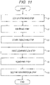
- Fig. 11 is a flowchart showing an example of a method for compressing a biological surface.
- the compression method shown in Fig. 11 includes a cover attaching step S1, an adhering step S2, a cover detaching step S3, a first compression step S4, a removing step S5, and a second compression step S6.
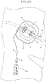
- Fig. 12A is a diagram showing an outline of the cover attaching step S1.
- Fig. 12B is a diagram showing an outline of the adhering step S2.
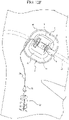
- FIG. 12C is a diagram showing an outline of the cover detaching step S3.
- Fig. 12D is a diagram showing an outline of the first compression step S4.
- Fig. 12E is a diagram showing an outline of the removing step S5.
- Fig. 12F is a diagram showing an outline of the second compression step S6,
- the compression method shown in Figs. 11 to 12F is a method for compressing a biological surface BS to narrow or obstruct a perforation leading from the biological surface to a vein without obstructing the vein.
- the perforation is formed by removing a sheath as a medical device 100 in a state of being inserted into a vein such as a femoral vein from the biological surface BS through a connective tissue.
- a sheath as a medical device 100 in a state of being inserted into a vein such as a femoral vein from the biological surface BS through a connective tissue.
- FIG. 13A shows a state in which the sheath as the medical device 100 is inserted into a femoral vein FV from the biological surface BS through a connective tissue CT.
- Fig. 13A shows three sheaths as the medical devices 100, and the number of sheaths may be two or less, or may be four or more.
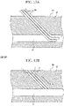
- Fig. 13B shows a state after the sheaths as the medical devices 100 are removed from the state shown in Fig. 13A . As shown in Fig. 13B , when the sheaths as the medical devices 100 are removed, the perforations P are formed between the biological surface BS and the femoral vein FV. In the compression method shown in Figs.
- the perforations P can be narrowed or obstructed without obstructing the femoral vein FV. Therefore, even when bleeding from a vein located at a deep position from the biological surface is stopped, bleeding can be stopped relatively efficiently without narrowing or obstructing the vein itself.
- the details of the steps S1 to S6 will be described with reference to Figs. 12A to 12F .
- Fig. 12A shows a state in which the cover member 51 is attached to the compression member 3 of the compression device 1.
- the cover member 51 can be attached to the compression device 1 by covering the compression device 1 from above.
- the cover member 51 according to the present embodiment is attached to the compression member 3 of the compression device 1 whilein contact with the entire upper surface of the peripheral portion 13 (see Fig. 3 or the like) of the adhesive sheet 2.
- Fig. 12A shows a state in which the sheath as the medical device 100 is inserted from the biological surface BS into the femoral vein FV (see Figs. 13A and 13B ).
- Fig. 12B shows a state in which the compression device 1, to which the cover member 51 is attached, is attached at a predetermined position on the biological surface BS in a state in which the sheath as the medical device 100 is inserted into the living body.
- Fig. 12C shows a state in which the cover member 51 is detached from the compression device 1 after the compression device 1 is attached to the biological surface BS.
- Figs. 12A to 12C show the use state of the compression device 1 after the release sheet 4 (see Fig. 1 or the like) is released from the adhesion surface 11.
- the compression device 1 is covered with the cover member 51, and is adhered to the biological surface BS in a state in which the cover member 51 is integrated.
- the adhesion surface 11 of the adhesive sheet 2 is adhered to the biological surface BS in a state in which a portion of the sheath as the medical device 100 inserted into the living body from the biological surface BS, the portion being exposed to the outside from the biological surface BS, is received by the receiving portion 6 of the compression device 1 and the receiving portion 55 of the cover member 51.
- the second portion X2 (see Fig. 3 or the like) of the adhesive sheet 2 of the compression device 1 can also be pressed toward the biological surface BS by the cover member 51. Accordingly, the second portion X2 of the adhesive sheet 2 can be easily adhered to the biological surface BS. More specifically, according to the present embodiment, the entire region of the peripheral portion 13 (see Fig. 3 or the like) of the adhesive sheet 2 can be pressed toward the biological surface BS via the cover member 51, and the entire region of the peripheral portion 13 can be adhered to the biological surface BS.
- the cover member 51 is detached from the compression device 1.
- the distance between the clamping portions 52 can be increased. Accordingly, the clamping portion 52 of the cover member 51 can be changed from a state in which the holding body 22 of the compression device 1 is clamped to a state in which the holding body 22 is not clamped. Therefore, the cover member 51 can be detached from the compression device 1.
- the cover member 51 may be detached from the compression device 1 without using the pair of gripping portions 54.
- the cover member 51 may be detached from the compression device 1 by pulling up the cover member 51 against a frictional force between parts at which the cover member 51 and the compression device 1 come into contact with each other.
- a syringe 30 as the fluid supply device is connected to the connection portion 29 of the tube 28.
- air is supplied to the internal spaces 40a (see Fig. 6 ) of the inflatable body 40 to inflate the inflatable body 40.
- the medical device 100 is compressed before being removed from the biological surface BS. Accordingly, immediately after the sheath as the medical device 100 is removed, the biological surface BS can be compressed. Therefore, the perforations P (see Fig. 13B ) extending from the biological surface BS to the femoral vein FV (see Figs. 13A and 13B ) can be narrowed or obstructed immediately after the sheaths are removed.
- the sheath as the medical device 100 is removed from the biological surface BS.
- the perforations P shown in Fig. 13B are formed by removing the sheaths.
- the biological surface BS is not compressed at all in this state, bleeding from the femoral vein FV to the outside of the living body through the perforations P and the wound on the biological surface BS occurs.
- the biological surface BS is compressed in advance before the sheath as the medical device 100 is removed from the biological surface BS. Therefore, the biological surface BS can be compressed to narrow or obstruct the perforations P (see Fig. 13B ) immediately after the sheaths are removed, and the amount of bleeding immediately after the sheaths are removed can be reduced.
- the syringe 30 as the fluid supply device is connected again to the connection portion 29 of the tube 28. Air is supplied again to pressurize the internal spaces 40a of the inflatable body 40 of the compression device 1 through the tube 28, or the air is evacuated from the internal spaces 40a to reduce the pressure.
- the compression force on the biological surface BS is adjusted after the sheath as the medical device 100 is removed. Accordingly, by adjusting the compression force on the biological surface BS and further narrowing or obstructing the perforations P (see Fig. 13B ) without obstructing the femoral vein FV (see Figs. 13A and 13B ), the amount of bleeding can be greatly reduced or the bleeding can be stopped.
- the compression force is slowly increased to increase the pressure until the bleeding is stopped.
- the compression force is slowly reduced to reduce the pressure until the bleeding is confirmed.
- the compression force is slowly increased to pressurize until the bleeding is stopped. Accordingly, it is possible to prevent the obstruction of the femoral vein FV (see Figs. 13A and 13B ) due to excessive pressurization.
- the biological surface BS is appropriately compressed may be detected using an ultrasonic device.
- the inflatable body 40 as the expander 21 (see Fig. 6 or the like) and the holding body 22 are formed of a material having ultrasonic transmissibility, and a fluid having ultrasonic transmissibility such as water is supplied to the inflatable body 40. Accordingly, a compression state made by the compression device 1 can be diagnosed by ultrasounds. That is, the ultrasonic device can detect whether the femoral vein FV (see Figs. 13A and 138 ) is obstructed. The compression force of the compression device 1 may be adjusted based on a diagnosis result by the ultrasonic device.
- the bleeding can be stopped.
- the compression device 1 is detached from the biological surface BS by releasing the adhesion surface 11 of the adhesive sheet 2 from the biological surface BS.
- the perforations P are narrowed or obstructed without obstructing the femoral vein FV (see Figs. 13A and 13B ).
- the bleeding can be stopped by narrowing or obstructing the perforations P (see Fig. 13B ).
- the blood leaks and spreads in the connective tissue CT (see Figs. 13A and 13B ), and thus the bleeding cannot be stopped.
- the biological surface BS it is preferable to compress the biological surface BS to a position at which a compression depth from the biological surface BS is 5 mm to 20 mm.
- the compression depth is more preferably 5 mm to 15 mm, and even more preferably 8 mm to 12 mm.
- compression pressure is pressure after the sheath as the medical device 100 is removed, and does not mean the above-mentioned compression force before the sheath is removed.
- the compression pressure is more preferably 50 g/cm 2 to 400g/cm 2 , and even more preferably 100 g/cm 2 to 300 g/cm 2 .
- the phrase "compressing the biological surface BS along a direction orthogonal to an extending direction of the perforations" means not only compressing only in the direction orthogonal to the extending direction of the perforations but also compressing in a direction inclined at an angle equal to or less than a predetermined angle (for example, 30 degrees or less) with respect to the direction orthogonal to the extending direction of the perforations.
- the compression device 1 according to the present embodiment can compress the biological surface BS along the direction orthogonal to the extending direction of the perforations P (see Fig. 13B ).
- the first inflatable portion 41a and the second inflatable portion 41b of the inflatable body 40 according to the present embodiment are inflated toward the direction inclined with respect to the sheet thickness direction A, as described above. Accordingly, the biological surface can be compressed along the direction orthogonal to the extending direction of the perforations P (see Fig. 13B ).
- the sheath as the medical device 100 is inserted not in a direction orthogonal to the biological surface BS (the same direction as the sheet thickness direction A) but in a direction inclined to one side with respect to the direction orthogonal to the biological surface BS. Therefore, as shown in Fig.
- the extending direction of the perforations P is also inclined with respect to the direction orthogonal to the biological surface BS. Therefore, when the first inflatable portion 41a and the second inflatable portion 41b can be inflated in a direction inclined to a side opposite to the extending direction of the perforations P (hereinafter, may be referred to as an "inclination direction F") with respect to the sheet thickness direction A which is the direction orthogonal to the biological surface BS, the biological surface BS is easily compressed along the direction orthogonal to the extending direction of the perforations P. Accordingly, it is easy to implement the compression device 1 that narrows or obstructs the perforations P without obstructing the vein such as the femoral vein FV in Figs.
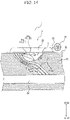
- Fig. 14 is a diagram showing the state in which the perforations P shown in Fig. 13B are narrowed or obstructed by the compression device 1. As shown in Fig. 14 , the perforations P are more easily narrowed or obstructed without further obstructing the vein such as the femoral vein FV by the compression device 1.
- the bleeding can be stopped by narrowing or obstructing the perforations P (see Fig. 13B ) without obstructing the vein such as the femoral vein FV.
- the compression method using the compression device 1, it is possible to stop the bleeding by a simple method without compression by a hand of the health care worker or using a large-scale hemostasis device.
- the inflatable body 40 of the compression member 3 can compress the biological surface toward the inclination direction F inclined with respect to a vertical direction (in Fig. 14 , the vertical direction is the same direction as the sheet thickness direction A, and is an upward-downward direction in Fig. 14 .
- a vertical direction perpendicular to the biological surface BS in a state in which the adhesive sheet 2 is attached to the living body. Accordingly, as shown in Fig. 14 , the perforations P are easily narrowed or obstructed without obstructing the vein such as the femoral vein FV.
- Fig. 15 is a front view of the state shown in Fig. 14 as seen from a biological surface BS side.
- Fig. 15 shows a front view of the biological surface BS at a position compressed by the compression device 1.
- the phrase "front view of the biological surface at a position compressed by the compression device” means a state in which a portion of the biological surface to be compressed by the compression device is seen from a direction perpendicular to the portion before the compressing.
- Fig. 15 shows a front view of an inguinal region. In the front view shown in Fig. 15 , a direction in which the biological surface BS is compressed (see a white arrow "AR1" in Fig.
- the perforations P are easily narrowed or obstructed without obstructing the vein such as the femoral vein FV.
- the extending direction G of the perforations P is inclined with respect to the biological surface BS and is also inclined with respect to the vertical direction (upward-downward direction in Fig. 14 ) perpendicular to the biological surface BS.
- a compression direction of the compression device 1 on the biological surface BS is also inclined with respect to the biological surface BS and also inclined with respect to the vertical direction (upward-downward direction in Fig. 14 ) perpendicular to the biological surface BS.
- the extending direction G of the perforations P is inclined to the side opposite to the inclination direction F as the compression direction of the compression device 1 on the biological surface with respect to the vertical direction (upward-downward direction in Fig. 14 ). That is, the compression of the compression device 1 on the biological surface is executed such that the compression direction intersects with the extending direction G of the perforations P. Accordingly, the perforations P can be efficiently narrowed or obstructed.
- Fig. 16 is a view showing a compression device set 2000 as a modification of the compression device set 1000.
- the compression device set 2000 shown in Fig. 16 differs from the compression device set 1000 (see Fig. 1 or the like) in a configuration for locking a cover member to a compression device, other aspects are the same as described above. Therefore, differences between the compression device set 2000 and the compression device set 1000 (see Fig. 1 or the like) will be mainly described here.
- Fig. 16 is a cross-sectional view of the compression device set 2000 in an attached state.
- Fig. 16 is the section view of the compression device set 2000 at the same position as the cross section of the compression device set 1000 shown in Fig. 10 (see Fig. 1 or the like).
- the cover member 51 includes a side-end engaging portion 252.
- the side-end engaging portion 252 engages with the opposite portions of the side end surface 22b of the holding body 22 of the compression device 1, respectively.
- the side-end engaging portion 252 is constituted by the pair of first plate portions 51 b1 of the cover member 51.
- the side-end engaging portion 252 of the cover member 51 is provided with convex portions 252a.
- concave portions 22b1 that are fitted with the convex portions 252a are provided at the opposite portions of the side end surface 22b of the holding body 22.
- the facing distance distance between left and right sides in Fig. 16
- the cover member 51 is provided with the convex portions 252a on facing surfaces of the pair of first plate portions 51b1.
- the concave portions 22b1 are formed at the opposite portions of the side end surface 22b of the holding body 22 sandwiched between the pair of first plate portions 51b1.
- a locked state between the cover member 51 and the compression device 1 can be further stabilized.
- the cover member 51 is provided with the convex portions 252a, and the compression device 1 is provided with the concave portions 22b1, but this disclosure is not limited to this configuration.
- the cover member 51 may be provided with concave portions, and the compression device 1 may be provided with convex portions.
- the cover member 51 may be provided with both a convex portion and a concave portion, and the compression device 1 may be provided with a concave portion to be fitted with the convex portion of the cover member 51 and a convex portion to be fitted into the concave portion of the cover member 51.
- a shape or the like of the concave and convex portions is not particularly limited.
- the cover member 51 shown in Fig. 16 is also provided with the sheet cover portion 53 that protrudes from the side-end engaging portion 252 in the sheet in-plane direction B, as in the embodiment.
- the sheet cover portion 53 comes into contact with the upper surface of at least a part of the second portion X2 of the adhesive sheet 2 (the entire region of the peripheral portion 13 in the example shown in Fig. 16 ) in a state in which the side-end engaging portion 252 engages with the opposite portions of the side end surface 22b of the holding body 22.
- This disclosure relates to a compression device and a method for attaching a device.
Landscapes
- Health & Medical Sciences (AREA)
- Life Sciences & Earth Sciences (AREA)
- Engineering & Computer Science (AREA)
- Biomedical Technology (AREA)
- Heart & Thoracic Surgery (AREA)
- Animal Behavior & Ethology (AREA)
- General Health & Medical Sciences (AREA)
- Public Health (AREA)
- Veterinary Medicine (AREA)
- Vascular Medicine (AREA)
- Surgery (AREA)
- Biophysics (AREA)
- Hematology (AREA)
- Dermatology (AREA)
- Reproductive Health (AREA)
- Nuclear Medicine, Radiotherapy & Molecular Imaging (AREA)
- Medical Informatics (AREA)
- Molecular Biology (AREA)
- Pulmonology (AREA)
- Anesthesiology (AREA)
- Surgical Instruments (AREA)
- Media Introduction/Drainage Providing Device (AREA)
- Materials For Medical Uses (AREA)
Abstract
Description
- This disclosure generally relates to a compression device set and a method for attaching a device.
- In recent years, in medical institutions, various forms of examinations or treatments are performed using elongated hollow tubular medical devices called catheters. A catheter is percutaneously inserted into a blood vessel from a puncture site formed at a wrist, an inguinal region, and the like, and is carried through the blood vessel to a site to be examined or treated. After an examination or treatment by a health care worker is completed, the catheter, or a sheath used to introduce the catheter, is removed from the puncture site, and the puncture site is stopped from bleeding.
- Patent document 1 discloses a compression device that compresses a wound of a patient or its vicinity after a sheath is removed. The compression device disclosed in the patent document 1 includes an adhesive sheet having an adhesion surface and a compression member attached to the adhesive sheet. The disclosed adhesive sheet in the patent document 1 includes a first portion to which a fixing portion of the compression member is fixed, and a second portion to which the fixing portion of the compression member is not fixed.
- Patent document 1:
WO 2019/221201 - The compression device disclosed in the patent document 1 is unlikely to be released from a biological surface, since the adhesive sheet includes the second portion. However, the second portion of the adhesive sheet includes a portion that is not covered by the compression member. Therefore, when the compression device is attached to the biological surface, the portion of the second portion of the adhesive sheet which is not covered by the compression member is unlikely to be pressed against the biological surface. That is, in the compression device disclosed in the patent document 1, there is still room for improvement from a viewpoint of operability when the second portion of the adhesive sheet is adhered to the biological surface.
- Disclosed here are a compression device set and a method for attaching a device that are capable of implementing a compression device that is easily attached to a biological surface and that is unlikely to be released from the biological surface.
- According to a first aspect of this disclosure, a compression device set includes: a compression device that is configured to be adhered to a biological surface and that is configured to compress the biological surface; and a cover member configured to be attached to and detached from the compression device. The compression device includes: an adhesive sheet having, on a lower surface, an adhesion surface configured to be adhered to the biological surface; and a compression member that is fixed to the adhesive sheet on an upper surface side of the adhesive sheet and that is configured to compress the biological surface in a state in which the adhesion surface of the adhesive sheet is adhered to the biological surface. The adhesive sheet includes a first portion that is in contact with the compression member and a second portion that is not in contact with the compression member. The cover member is configured to be attached to the compression member in a state in which the cover member is configured to come into contact with an upper surface of at least a part of the second portion of the adhesive sheet.
- According to one embodiment of this disclosure, the compression member of the compression device includes: an expander that is expandable; and a holding body configured to hold the expander to be expandable in a sheet thickness direction of the adhesive sheet, and the cover member is configured to be attached to the holding body.
- According to one embodiment of this disclosure, the second portion of the adhesive sheet includes a peripheral portion located outside an outer edge of the holding body in a plan view seen in the sheet thickness direction, and the cover member is configured to be attached to the holding body in a state in which the cover member is configured to come into contact with an upper surface of the entire peripheral portion.
- According to one embodiment of this disclosure, the cover member is locked to the holding body by engaging with a side end surface of the holding body, the side end surface being located in a sheet in-plane direction orthogonal to the sheet thickness direction.
- According to one embodiment of this disclosure, the cover member includes: a clamping portion configured to clamp opposite portions of the side end surface of the holding body; and a sheet cover portion that protrudes from the clamping portion in the sheet in-plane direction and that is configured to come into contact with the upper surface of at least a part of the second portion of the adhesive sheet in the state in which the clamping portion clamps the opposite portions of the side end surface of the holding body.
- According to one embodiment of this disclosure, the cover member includes a pair of gripping portions extending from the clamping portion in the sheet thickness direction, and by changing a facing distance between the pair of gripping portions, the cover member is switchable between a locking position at which the clamping portion clamps the opposite portions of the side end surface of the holding body and a locking release position at which the clamping portion does not clamp the opposite portions of the side end surface of the holding body.
- According to one embodiment of this disclosure, the cover member includes: a side-end engaging portion that engages with each of the opposite portions of the side end surface of the holding body; and a sheet cover portion that protrudes from the side-end engaging portion in the sheet in-plane direction and that is configured to come into contact with the upper surface of at least a part of the second portion of the adhesive sheet in the state in which the side-end engaging portion engages with the opposite portions of the side end surface of the holding body, one of the side-end engaging portion and the opposite portions of the side end surface of the holding body is provided with a convex portion, and the other one of the side-end engaging portion and the opposite portions of the side end surface of the holding body is provided with a concave portion or a hole portion that is fitted with the convex portion.
- According to one embodiment of this disclosure, the cover member includes a pair of gripping portions each extending in the sheet thickness direction from the side-end engaging portion, and by changing a facing distance between the pair of gripping portions, the cover member is switchable between a locking position at which the convex portion is fitted into the concave portions or the hole portions and a locking release position at which the convex portion is not fitted into the concave portion or the hole portion.
- According to a second aspect of this disclosure, there is provided a method for attaching a compression device to a biological surface. The compression device is configured to be adhered to the biological surface and is configured to compress the biological surface. The compression device includes: an adhesive sheet having, on a lower surface, an adhesion surface configured to be adhered to the biological surface; and a compression member that is fixed to the adhesive sheet on an upper surface side of the adhesive sheet and that is configured to compress the biological surface in a state in which the adhesion surface of the adhesive sheet is adhered to the biological surface, the adhesive sheet includes a first portion that is in contact with the compression member and a second portion that is not in contact with the compression member. The method includes: an attaching step of attaching a cover member to the compression member in a state in which the cover member is configured to come into contact with an upper surface of at least a part of the second portion of the adhesive sheet; and an adhering step of pressing at least a part of the second portion of the adhesive sheet toward the biological surface via the cover member, and adhering at least the part of the second portion to the biological surface.
- According to this disclosure, it is possible to provide the compression device set and the method for attaching the device that are capable of implementing the compression device that is easy to be attached to the biological surface and that is unlikely to be released from the biological surface.
-
- [
Fig. 1] Fig. 1 is a perspective view of a compression device set in a state in which a cover member is not attached to a compression device according to one embodiment of this disclosure. - [
Fig. 2] Fig. 2 is a perspective view of the compression device set shown inFig. 1 in a state in which the cover member is detachably attached to the compression device. - [
Fig. 3] Fig. 3 is a top view of the compression device shown inFig. 1 . - [
Fig. 4] Fig. 4 is a bottom view of the compression device shown inFig. 1 . - [
Fig. 5] Fig. 5 is a cross-sectional view of the compression device shown inFig. 1 in a state in which an inflatable body is in a deflated form. - [
Fig. 6] Fig. 6 is a cross-sectional view of the compression device shown inFig. 1 in a state in which the inflatable body is in an inflated form. - [
Fig. 7] Fig. 7 is a perspective view of the cover member shown inFig. 1 from a lower side. - [
Fig. 8] Fig. 8 is a top view of the cover member shown inFig. 1 . - [
Fig. 9] Fig. 9 is a bottom view of the cover member shown inFig. 1 . - [
Fig. 10] Fig. 10 is a cross-sectional view taken along a line X-X inFig. 2 . - [
Fig. 11] Fig. 11 is a flowchart showing an example of a method for compressing a biological surface using the compression device shown inFig. 1 , the method including a method for attaching the compression device to the biological surface, according to one embodiment of this disclosure. - [
Fig. 12A] Fig. 12A is a diagram showing an outline of a cover attaching step inFig. 11 . - [
Fig. 12B] Fig. 12B is a diagram showing an outline of an adhering step inFig. 11 . - [
Fig. 12C] Fig. 12C is a diagram showing an outline of a cover detaching step inFig. 11 . - [
Fig. 12D] Fig. 12D is a diagram showing an outline of a first compression step inFig. 11 . - [
Fig. 12E] Fig. 12E is a diagram showing an outline of a removing step inFig. 11 . - [
Fig. 12F] Fig. 12F is a diagram showing an outline of a second compression step inFig. 11 . - [
Fig. 13A] Fig. 13A is a diagram showing a state in which a medical insertion member is inserted into a femoral vein from a biological surface through a connective tissue. - [
Fig. 13B] Fig. 13B is a diagram showing a state after the medical insertion member is removed from the state shown inFig. 13A . - [
Fig. 14] Fig. 14 is a diagram showing a state in which perforations shown inFig. 13B are narrowed or obstructed by the compression device shown inFig. 1 . - [
Fig. 15] Fig. 15 is a front view of the state shown inFig. 14 as seen from a biological surface side. - [
Fig. 16] Fig. 16 is a view showing a modification of the compression device set shown inFig. 1 . - Hereinafter, a compression device set and a method for attaching a device according to this disclosure will be exemplified with reference to the drawings. In the drawings, common members and portions are denoted by the same reference numerals.
-
Fig. 1 is a view showing a compression device set 1000 according to one embodiment of the compression device set according to this disclosure. As shown inFig. 1 , thecompression device set 1000 includes a compression device 1 and acover member 51. Thecover member 51 can be attached to and detached from the compression device 1.Fig. 1 shows the compression device set 1000 in a state in which thecover member 51 is not attached to the compression device 1.Fig. 2 shows the compression device set 1000 in a state in which thecover member 51 is detachably attached to the compression device 1.Figs. 1 and2 show the compression device 1 in a state in which arelease sheet 4 is attached to anadhesion surface 11 of anadhesive sheet 2. Therelease sheet 4 is released when the compression device 1 is attached to a biological surface. -
Figs. 3 and4 are plan views of the compression device 1. Specifically,Fig. 3 is a top view of the compression device 1.Fig. 4 is a bottom view of the compression device 1.Figs. 5 and6 are section views of the compression device 1 in a cross section taken along the section line V-V and VI-Vi respectively inFig. 3 . The details will be described later, andFigs. 5 and6 show different states of the compression device 1. In addition,Figs. 3 to 6 show the compression device 1 in a state in which the release sheet 4 (seeFig. 1 or the like) is removed. - The compression device 1 can be adhered to the biological surface. In addition, the compression device 1 can compress the biological surface in a state of being adhered to the biological surface.
- The compression device 1 includes the
adhesive sheet 2 and acompression member 3. - The
adhesive sheet 2 has, on a lower surface, theadhesion surface 11 that can be adhered to the biological surface. Thecompression member 3 is fixed to theadhesive sheet 2 on an upper surface side of theadhesive sheet 2. In addition, thecompression member 3 can compress the biological surface in a state in which theadhesion surface 11 of theadhesive sheet 2 is adhered to the biological surface. - Accordingly, the compression device 1 is fixed to a position on the biological surface by adhering the
adhesion surface 11 of theadhesive sheet 2 to the biological surface. In addition, the compression device 1 can compress a predetermined site on the biological surface by thecompression member 3 in a state in which the compression device 1 is fixed to the position on the biological surface by theadhesion surface 11 of theadhesive sheet 2. A predetermined site on the biological surface includes, for example, a wound on the biological surface or its vicinity formed by inserting an elongated medical device such as a puncture needle, a catheter, and a sheath, from the biological surface, into a blood vessel of a living body. After the medical device is removed from the living body, bleeding can be stopped by compressing the wound on the biological surface or its vicinity by thecompression member 3. - Hereinafter, the details of each member and each portion of the compression device 1 will be described.
- The
adhesive sheet 2 has theadhesion surface 11 on the lower surface located on one side in a sheet thickness direction A. In addition, theadhesive sheet 2 has, on an upper surface located on the other side in the sheet thickness direction A, an attachingsurface 12 to which thecompression member 3 is attached. Theadhesive sheet 2 has flexibility. Therefore, theadhesive sheet 2 can be deformed according to a shape of the biological surface. In addition, theadhesion surface 11 easily follows deformation of the biological surface. As a result, it is possible to prevent the compression device 1 from being unintentionally released from the biological surface. - Hereinafter, for convenience of description, the one side in the sheet thickness direction A, which is a direction from the attaching
surface 12 to theadhesion surface 11 in the sheet thickness direction A, may be simply referred to as a "downward direction A1". In addition, for convenience of description, the other side in the sheet thickness direction A, which is a direction from theadhesion surface 11 to the attachingsurface 12 in the sheet thickness direction A, may be simply referred to as an "upward direction A2". Further, in a plan view (seeFigs. 3 and4 ) of the compression device 1 seen along the sheet thickness direction A of theadhesive sheet 2, a plan view (seeFig. 3 ) of the compression device 1 seen from an attachingsurface 12 side of theadhesive sheet 2 may be simply referred to as a "top view" for convenience of description. In addition, in the plan view (seeFigs. 3 and4 ) of the compression device 1 seen along the sheet thickness direction A of theadhesive sheet 2, a plan view (seeFig. 4 ) of the compression device 1 seen from anadhesion surface 11 side of theadhesive sheet 2 may be simply referred to as a "bottom view" for convenience of description. In addition, when the top view and the bottom view are not distinguished from each other, the "plan view" is simply referred to. In addition, unless otherwise specified, the simple descriptions of the "plan view", the "top view", and the "bottom view" mean a plan view, a top view, and a bottom view when anexpander 21 of thecompression member 3 to be described later is in a retracted form. - The
adhesive sheet 2 includes a plurality of layers including, for example, a base material layer and an adhesive layer. - The base material layer is formed of, for example, a thin resin sheet. More specifically, the base material layer is formed of, for example, a white spunlace nonwoven fabric of polyester fibers, and has a thickness in a range of 5 µm to 150 µm, and for example, 30 µm. However, a material of the base material layer is not limited to polyester, and an acrylic polymer, polyethylene, an ethylene-vinyl acetate copolymer, polyurethane, a polyamide derivative, and the like may be used.
- The adhesive layer is formed of an adhesive such as a rubber-based adhesive, an acrylic-based adhesive, and a silicon-based adhesive, for example. The adhesive layer is stacked on the base material layer directly or indirectly with another layer interposed therebetween. The
adhesion surface 11 of theadhesive sheet 2 according to the present embodiment is an adhesive layer. - The
adhesive sheet 2 may further include another layer in addition to the above-mentioned base material layer and the adhesive layer. Theadhesive sheet 2 may include, for example, a surface layer. The surface layer is formed of, for example, a resin having a thickness of about 5 µm to 50 µm. More specifically, examples of a material of the surface layer include polyester, polyamide, polyamideimide, polyethylene, polypropylene, polycarbonate, polyurethane, polyvinyl chloride, and fluororesin. The surface layer is stacked on the base material layer directly or indirectly with another layer interposed therebetween on a side opposite to the adhesive layer with the base material layer interposed therebetween. Therefore, the attachingsurface 12 of theadhesive sheet 2 may be a surface layer. - More specifically, the
adhesive sheet 2 may be formed of, for example, a nonwoven fabric tape having an adhesive agent as an adhesive on one surface thereof. Further, theadhesive sheet 2 may be formed of, for example, a double-sided tape in which adhesive layers are provided on both sides of the base material layer. When theadhesive sheet 2 is formed of the double-sided tape, thecompression member 3 can be fixed to theadhesive sheet 2 by being adhered to one adhesive layer of theadhesive sheet 2. - The
adhesive sheet 2 according to the present embodiment extends in a C shape in the plan view shown inFigs. 3 and4 . In other words, theadhesive sheet 2 according to the present embodiment defines a central opening region in the plan view. In the central opening region, a receivingportion 6 to be described later constitutes an open region communicating with the outside. The open region in the central opening region is a gap region sandwiched between both end portions of the C-shapedadhesive sheet 2 in the plan view. - As described above, the
adhesive sheet 2 according to the present embodiment extends in the C shape in the plan view, but is not limited to the shape. Theadhesive sheet 2 may have, for example, an endless outer shape in the plan view. An outer edge shape and an inner edge shape of the endless adhesive sheet in the plan view are not particularly limited. The outer edge shape and the inner edge shape of the adhesive sheet having the endless outer shape in the plan view can be various shapes such as a circular shape, an oval shape, and a polygonal shape including a square shape. - In the adhesive sheet having the endless outer shape in the plan view, it is preferable that a slit extending from an outer edge to an inner edge is formed. By providing such a slit, the central opening region and the outside communicate with each other through the slit. Therefore, a medical device such as a catheter and a sheath can be moved from the outside of the adhesive sheet into the central opening region through the slit.
- Next, a first portion X1 and a second portion X2 of the
adhesive sheet 2 will be described. - As shown in
Figs. 3 and4 , and the like, theadhesive sheet 2 includes the first portion X1 that comes into contact with thecompression member 3 and the second portion X2 that does not come into contact with thecompression member 3. The first portion X1 means a region of theadhesive sheet 2 in a sheet in-plane direction B in which thecompression member 3 comes into contact with the upper surface side. In addition, the second portion X2 means a region of theadhesive sheet 2 in the sheet in-plane direction B in which thecompression member 3 does not come into contact with the upper surface side. Therefore, for example, if a portion is covered with thecompression member 3 on the upper surface side and comes into contact with thecompression member 3, the portion corresponds to the first portion X1 regardless of whether thecompression member 3 is fixed. Theadhesion surface 11 is provided in at least a part of a region of a lower surface of the first portion X1 and at least a part of a region of a lower surface of the second portion X2. More specifically, theadhesion surface 11 according to the present embodiment is provided on the entire lower surface of the first portion X1 and the entire lower surface of the second portion X2. That is, theadhesion surface 11 according to the present embodiment is provided on the entire lower surface of theadhesive sheet 2. Since theadhesive sheet 2 of the compression device 1 includes the second portion X2, it is possible to prevent theadhesive sheet 2 from being unintentionally released from the biological surface. The effect is based on the same principle as that described in the patent document 1. - As shown in
Fig. 3 or the like, theadhesive sheet 2 according to the present embodiment includes aperipheral portion 13 located on an outer periphery of thecompression member 3 in the plan view. Theperipheral portion 13 of theadhesive sheet 2 according to the present embodiment is the second portion X2 that does not come into contact with thecompression member 3. In other words, the second portion X2 of theadhesive sheet 2 includes theperipheral portion 13 located outside an outer edge of a holdingbody 22, which will be described later, of thecompression member 3 in the plan view. - As shown in
Fig. 3 or the like, according to the present embodiment, theperipheral portion 13 of theadhesive sheet 2 does not surround the entire periphery of thecompression member 3 in the plan view. That is, there is a position at which theperipheral portion 13 of theadhesive sheet 2 is not provided in the periphery of thecompression member 3. At the position at which theperipheral portion 13 of theadhesive sheet 2 is not provided, a portion of the medical device such as a sheath inserted into the living body that extends outside the living body is received. That is, the receivingportion 6 that can receive the medical device such as a sheath is defined at the position at which theperipheral portion 13 of theadhesive sheet 2 is not provided in the periphery of thecompression member 3. Accordingly, the compression device 1 can be attached to the biological surface in a state in which the portion of the medical device such as a sheath whose distal end side is inserted into the living body which extends outside the living body is received by the receivingportion 6. Therefore, even in a state in which the medical device such as a sheath is inserted into the living body, it is easy to dispose theexpander 21, which will be described later, of thecompression member 3 such that the wound on the biological surface formed by the medical device or its vicinity is covered. That is, in such an arrangement state, the compression device 1 can be easily attached to the biological surface. As a result, in both the state in which the medical device such as a sheath is inserted into the living body and a state in which the medical device is removed from the living body, the wound on the biological surface or its vicinity is easily compressed by theexpander 21 of thecompression member 3 of the compression device 1. - The
compression member 3 is fixed to theadhesive sheet 2 on the upper surface side of theadhesive sheet 2. Specifically, thecompression member 3 according to the present embodiment is fixed to the attachingsurface 12 of theadhesive sheet 2. In addition, thecompression member 3 can compress the biological surface in a state in which theadhesion surface 11 of theadhesive sheet 2 is adhered to the biological surface. Specifically, thecompression member 3 according to the present embodiment includes theexpander 21 that is expandable and the holdingbody 22 that holds theexpander 21 to be expandable in the sheet thickness direction A of theadhesive sheet 2. - As shown in
Figs. 3 and4 , and the like, the holdingbody 22 of thecompression member 3 according to the present embodiment includes a portion that overlaps with theadhesive sheet 2 and a portion that does not overlap with theadhesive sheet 2 in the plan view. More specifically, the holdingbody 22 of thecompression member 3 according to the present embodiment covers the central opening region of theadhesive sheet 2 in the plan view. A portion of the holdingbody 22 that overlaps with the central opening region in the plan view is the portion that does not overlap with theadhesive sheet 2. The holdingbody 22 according to the present embodiment covers the central opening region, and an outer edge portion of the holdingbody 22 in the plan view overlaps with theadhesive sheet 2. According to the present embodiment, the portion of the holdingbody 22 that overlaps with theadhesive sheet 2 in the plan view is in contact with and fixed to the attachingsurface 12 of theadhesive sheet 2. Alternatively, the entire region of the portion of the holdingbody 22 that overlaps with theadhesive sheet 2 in the plan view may not be in contact with and fixed to the attachingsurface 12 of theadhesive sheet 2. Therefore, only a small portion of the portion of the holdingbody 22 that overlaps with theadhesive sheet 2 in the plan view may be in contact with and fixed to the attachingsurface 12 of theadhesive sheet 2. Therefore, the portion of the holdingbody 22 that overlaps with theadhesive sheet 2 in the plan view may include, for example, a portion that comes into contact with the attachingsurface 12 of theadhesive sheet 2 but is not fixed thereto. Theexpander 21 according to the present embodiment, which will be described later, expands toward the downward direction A1 in the central opening region defined by theadhesive sheet 2 and can compress the biological surface. - The holding
body 22 according to the present embodiment has a rounded square shape in the plan view and has a flat outer shape in the sheet thickness direction A. The holdingbody 22 covers a firstinflatable portion 41a and a secondinflatable portion 41b of aninflatable body 40 to be described later as theexpander 21 in the upward direction A2. In addition, the holdingbody 22 is formed with a throughhole 22a through which an extendingportion 42 of theinflatable body 40 to be described later is inserted. Further, a lockingprotrusion 22c to which the extendingportion 42 of theinflatable body 40 to be described later is locked is provided on an upper surface of the holdingbody 22. - Examples of a material of the holding
body 22 include a resin material. Examples of the resin material include thermoplastic resins used in injection molding such as ABS resin, AS resin, polyethylene, polypropylene, polystyrene, polyvinyl chloride, polyvinylidene chloride resin, polyphenylene oxide, thermoplastic polyurethane, polymethylene methacrylate, polyoxyethylene, fluororesin, polycarbonate, polyamide, acetal resin, acrylic resin, and polyethylene terephthalate, and thermosetting resins such as phenol resin, epoxy resin, silicone resin, and unsaturated polyester. - The
expander 21 is held by the holdingbody 22. Theexpander 21 can protrude from theadhesion surface 11 of theadhesive sheet 2 toward the downward direction A1 as the one side in the sheet thickness direction A. In the compression device 1, theexpander 21 protrudes in the downward direction A1 from theadhesion surface 11 of theadhesive sheet 2 in a state in which theadhesion surface 11 of theadhesive sheet 2 is adhered to the biological surface. Accordingly, the biological surface is compressed by theexpander 21. - The
expander 21 according to the present embodiment is theinflatable body 40 that can be inflated toward the downward direction A1 of the sheet thickness direction A by supplying a fluid such as air to theinflatable body 40. When theinflatable body 40 according to the present embodiment is changed in form from a retracted form which is deflated as shown inFig. 5 to a protruding form which is inflated as shown inFig. 6 , theinflatable body 40 protrudes toward the downward direction A1 from theadhesion surface 11 of theadhesive sheet 2 in the sheet thickness direction A, and is in a posture capable of compressing the biological surface. - Specifically, the compression device 1 according to the present embodiment is adhered to the biological surface in the retracted form (see
Fig. 5 ) before theinflatable body 40 as theexpander 21 is inflated. Theinflatable body 40 is inflated by an operation of an operator such as a health care worker in a state in which the compression device 1 is fixed to the biological surface. Theinflatable body 40 is inflated into the protruding form (seeFig. 6 ). The compression device 1 according to the present embodiment can compress the predetermined site on the biological surface by changing theinflatable body 40 from the retracted form to the protruding form. As described above, the predetermined site on the biological surface is a wound or the like formed by inserting a medical device such as a sheath into the living body. After the above-mentioned medical device such as a sheath is removed from the living body, bleeding can be stopped by compressing the wound on the biological surface or its vicinity with theinflatable body 40 as theexpander 21 of the compression device 1. The details of a series of compression methods will be described later (seeFigs. 11 to 12F ). - As shown in
Fig. 5 , theinflatable body 40 as theexpander 21 according to the present embodiment is substantially flush with theadhesion surface 11 of theadhesive sheet 2 in the retracted form, and does not protrude from theadhesion surface 11 in the downward direction A1. The holdingbody 22 may include a locking mechanism that locks theinflatable body 40 so that theinflatable body 40 does not protrude beyond theadhesion surface 11 of theadhesive sheet 2 in the downward direction A1 in the retracted form. - The
inflatable body 40 according to the present embodiment definesinternal spaces 40a. Theinternal spaces 40a of theinflatable body 40 communicate with atube 28 that penetrates the holdingbody 22 and extends to the outside of the holdingbody 22. A fluid such as air is supplied through thetube 28 to theinternal spaces 40a of theinflatable body 40 from a fluid supply device such as a syringe connected to an inflation port as aconnection portion 29 provided at an end portion of thetube 28. Accordingly, theinflatable body 40 can be changed from the retracted form (seeFig. 5 ) to the protruding form (seeFig. 6 ). That is, theinflatable body 40 as theexpander 21 can protrude from theadhesion surface 11 of theadhesive sheet 2 in the downward direction A1. The fluid supplied to the internal spaces of theinflatable body 40 is not limited to gas, and may be a liquid. In addition, by suctioning the fluid from theinternal spaces 40a of theinflatable body 40, theinflatable body 40 can also be changed from the protruding form (seeFig. 6 ) to the retracted form (seeFig. 5 ). - More specifically, as shown in
Fig. 6 , theexpander 21 according to the present embodiment includes acontact portion 21a that comes into contact with the biological surface and directly compresses the biological surface, and apressing portion 21b that presses thecontact portion 21a in a predetermined direction to increase a compression force of thecontact portion 21a in the predetermined direction. Specifically, theinflatable body 40 as theexpander 21 according to the present embodiment includes the firstinflatable portion 41a as thecontact portion 21a and the secondinflatable portion 41b as thepressing portion 21b. - The first
inflatable portion 41a defines a first internal space 41a1. The secondinflatable portion 41b defines a second internal space 41b1. The first internal space 41a1 and the second internal space 41 b1 communicate with each other. In the retracted form of theinflatable body 40, the firstinflatable portion 41a and the secondinflatable portion 41b that are in a deflated state overlap with each other in the sheet thickness direction A. The firstinflatable portion 41a in the deflated state is located on a lower side, and the secondinflatable portion 41b in the deflated state is overlapped on an upper side. The secondinflatable portion 41b is covered with the holdingbody 22 in the upward direction A2. In addition, the firstinflatable portion 41 a and the secondinflatable portion 41b are continuous only on one end side (left side inFig. 6 ) in the sheet in-plane direction B orthogonal to the sheet thickness direction A. - The fluid supplied to the
internal spaces 40a of theinflatable body 40 through thetube 28 flows into the second internal space 41b1 of the secondinflatable portion 41b, and then flows into the first internal space 41a1 of the firstinflatable portion 41a. Therefore, when the fluid is supplied to theinternal spaces 40a of theinflatable body 40, the secondinflatable portion 41b is first inflated. As described above, since the secondinflatable portion 41b is covered by the holdingbody 22 in the upward direction A2, the secondinflatable portion 41 b to which the fluid is supplied is inflated in the downward direction A1. Next, the fluid flows into the first internal space 41a1 and the firstinflatable portion 41a is inflated. At this time, the firstinflatable portion 41a is inflated while pivoting about the one end side (left side inFig. 6 ) in the sheet in-plane direction B continuous with the secondinflatable portion 41b as a pivot center axis. That is, when the fluid is supplied to the first internal space 41a1 of the firstinflatable portion 41a, the firstinflatable portion 41a is pressed by the secondinflatable portion 41b, and thus the firstinflatable portion 41a is inflated such that the other end side (right side inFig. 6 ) moves in the downward direction A1 with respect to the one end side in the sheet in-plane direction B, and the firstinflatable portion 41a is in the protruding form shown inFig. 6 . Accordingly, a compression force in a predetermined direction (compression force in a lower left direction inFig. 6 ) by the firstinflatable portion 41a can be increased. - More specifically, the
inflatable body 40 according to the present embodiment includes a sheet-shaped extendingportion 42 extending from the firstinflatable portion 41a and the secondinflatable portion 41b. The firstinflatable portion 41a and the secondinflatable portion 41b according to the present embodiment are continuous with the extendingportion 42 on a receivingportion 6 side in the sheet in-plane direction B in a cross-sectional view inFigs. 5 and6 . At the time of inflation, the firstinflatable portion 41a and the secondinflatable portion 41b pivot about a portion of the extendingportion 42 connected to the firstinflatable portion 41a and the secondinflatable portion 41b as a hinge portion. In other words, the firstinflatable portion 41a and the secondinflatable portion 41b can be inflated not only toward the sheet thickness direction A but also toward a direction inclined with respect to the sheet thickness direction A. - According to the present embodiment, the sheet-shaped extending
portion 42 extending from a lower surface side to an upper surface side of the holdingbody 22 through the throughhole 22a of the holdingbody 22 is fixed to the holdingbody 22 on the upper surface side of the holdingbody 22. Accordingly, theinflatable body 40 according to the present embodiment is locked to the holdingbody 22. More specifically, a slit is formed in the extendingportion 42 according to the present embodiment. The lockingprotrusion 22c provided on the upper surface of the holdingbody 22 is inserted into the slit. Accordingly, the extendingportion 42 is positioned on the holdingbody 22. - More specifically, each of the first
inflatable portion 41a and the secondinflatable portion 41b according to the present embodiment is constituted by a balloon portion. As described above, the two balloon portions overlap with each other in the sheet thickness direction A. In addition, one end of each of the two balloon portions is attached to the extendingportion 42. That is, the one end side of each of the two balloon portions is restrained by the extendingportion 42. Therefore, even when the two balloon portions are inflated, the two balloon portions are not separated from each other on the one end side. On the other hand, the other end side of each of the two balloon portions is not restrained at all. Therefore, when the two balloon portions are inflated, the two balloon portions are separated from each other on the other end side. That is, in the two balloon portions constituting the firstinflatable portion 41a and the secondinflatable portion 41b according to the present embodiment, with the one end side attached to the extendingportion 42 as a pivot center, the other end side which is not attached to the extendingportion 42 pivots about the pivot center. Accordingly, the firstinflatable portion 41a and the secondinflatable portion 41b according to the present embodiment are inflated toward the direction inclined with respect to the sheet thickness direction A. Perforations P (seeFig. 13B ) to be described later are easily narrowed or obstructed by inflating theinflatable body 40 toward the direction inclined with respect to the sheet thickness direction A. The details will be described later (seeFig. 14 ). The configuration for inflating theinflatable body 40 toward the direction inclined with respect to the sheet thickness direction A is not limited to a configuration of theexpander 21 according to the present embodiment. - Materials that may be used to fabricatethe balloon portions constituting the first
inflatable portion 41a and the secondinflatable portion 41b include, for example, soft polyvinyl chloride, polyurethane, polyethylene, polypropylene, polyester, ethylene-vinyl acetate copolymer (EVA), silicone, or a material having flexibility obtained by mixing any of these materials. - The configuration of the
expander 21 is not particularly limited. Theexpander 21 may not have thepressing portion 21b. In addition, theexpander 21 may not be an inflatable body. Further, even when theexpander 21 is an inflatable body, theexpander 21 is not limited to the configuration of theinflatable body 40. -
Fig. 7 is a perspective view of thecover member 51 seen from a lower side.Fig. 8 is a top view of thecover member 51.Fig. 9 is a bottom view of thecover member 51.Fig. 10 is a section view of the compression device set 1000 in a state in which thecover member 51 is attached to the compression device 1. Specifically,Fig. 10 is a section view taken along a line X-X inFig. 2 . - As shown in
Figs. 2 and10 , thecover member 51 can be attached to thecompression member 3. In addition, as shown inFig. 10 , thecover member 51 can be attached to thecompression member 3 in a state in which thecover member 51 comes into contact with an upper surface of at least a part of the second portion X2 of theadhesive sheet 2. Therefore, when the compression device 1 is pressed against the biological surface in a state in which thecover member 51 is attached to the compression device 1, the second portion X2 of theadhesive sheet 2 can be pressed toward the biological surface by thecover member 51. Accordingly, theadhesion surface 11 provided on the lower surface of the second portion X2 of theadhesive sheet 2 is also easily adhered to the biological surface. That is, the second portion X2 of theadhesive sheet 2, which is unlikely to be released from the biological surface after being adhered, is easily adhered to the biological surface. As a result, according to thecompression device set 1000, it is possible to implement the compression device 1 that is easily attached to the biological surface and that is unlikely to be released from the biological surface. - Alternatively, the
cover member 51 may be attached to thecompression member 3 in a state in which thecover member 51 may come into contact with the upper surface of at least a part of the second portion X2 of theadhesive sheet 2. That is, in a state in which thecover member 51 is attached to thecompression member 3, thecover member 51 may not be in constant contact with the upper surface of at least a part of the second portion X2 of theadhesive sheet 2. In such a case, thecover member 51 may come into contact with the upper surface of at least a part of the second portion X2 of theadhesive sheet 2. As an example, in a state in which thecover member 51 is attached to the compression device 1, a part of the cover member 51 (for example, aflange plate portion 51c as asheet cover portion 53 to be described later according to the present embodiment) can be elastically deformed. By elastically deforming a part of thecover member 51, the part may come into contact with the upper surface of at least a part of the second portion X2 of theadhesive sheet 2. - By using the
cover member 51 that can be attached to and detached from thecompression member 3, a thickness of thecompression member 3 in the sheet thickness direction A can be reduced. Accordingly, a burden on a patient due to the compression device 1 placed on the biological surface can be reduced. - The
cover member 51 according to the present embodiment can be attached to the holdingbody 22 of thecompression member 3. In addition, thecover member 51 according to the present embodiment cannot be attached to theexpander 21 of thecompression member 3. Accordingly, an attaching position and an attaching posture of thecover member 51 with respect to thecompression member 3 are unlikely to change. Therefore, thecover member 51 can be more reliably attached to thecompression member 3 regardless of a change in the form of theexpander 21. In addition, a state in which thecover member 51 is attached to and integrated with thecompression member 3 can be further stabilized. As a result, it is possible to prevent thecover member 51 from being unintentionally detached from thecompression member 3. - The
cover member 51 according to the present embodiment can be attached to the holdingbody 22 of thecompression member 3 in a state in which thecover member 51 comes into contact with an upper surface of the entire region of theperipheral portion 13 of the second portion X2 of theadhesive sheet 2. Accordingly, theentire adhesion surface 11 provided on a lower surface of theperipheral portion 13 can be more reliably adhered to the biological surface. As a result, it is possible to further prevent the compression device 1 from being released from the biological surface. - As shown in
Fig. 10 , thecover member 51 is locked to the holdingbody 22 by engaging with aside end surface 22b of the holdingbody 22 that is located in the sheet in-plane direction B orthogonal to the sheet thickness direction A. Accordingly, when thecover member 51 is engaged with theside end surface 22b of the holdingbody 22, thecover member 51 is also easily flattened. - More specifically, as shown in
Fig. 10 , thecover member 51 according to the present embodiment includes a clampingportion 52, thesheet cover portion 53, and a pair ofgripping portions 54. - The clamping
portion 52 can clamp opposite portions of theside end surface 22b of the holdingbody 22. Thecover member 51 is locked to the compression device 1 by clamping the opposite portions of theside end surface 22b of the holdingbody 22 with the clampingportion 52. - More specifically, the
cover member 51 according to the present embodiment includes aceiling plate portion 51a having a rounded square shape with which the upper surface of the holdingbody 22 is covered, and aperipheral wall portion 51b that protrudes from an outer edge of theceiling plate portion 51a to one side of theceiling plate portion 51a in a thickness direction. Theperipheral wall portion 51b includes a pair of first plate portions 51b1 that protrude from facing portions of the outer edge of theceiling plate portion 51a and that face each other. In addition, theperipheral wall portion 51b includes a pair of second plate portions 51b2 that protrude from portions of the outer edge of theceiling plate portion 51a that are different from the portions from which the pair of first plate portions 51b1 protrude. The pair of second plate portions 51b2 face each other. In a plan view of theceiling plate portion 51a seen in the thickness direction, the pair of second plate portions 51b2 extend in a direction substantially orthogonal to the pair of first plate portions 51b1. The thickness direction of theceiling plate portion 51a of thecover member 51 coincides with the sheet thickness direction A in a state in which thecover member 51 is attached to the compression device 1 (seeFig. 2 ). Hereinafter, as shown inFigs. 1 and2 , a state in which thecover member 51 is located in the upward direction A2 with respect to the compression device 1 and theceiling plate portion 51a of thecover member 51 coincides with the sheet thickness direction A will be described as a reference. Therefore, hereinafter, the thickness direction of theceiling plate portion 51a of thecover member 51 is simply referred to as the "sheet thickness direction A". In addition, in the thickness direction of theceiling plate portion 51a of thecover member 51, a side on which the compression device 1 is located is referred to as the "downward direction A1", and an opposite side thereof is referred to as the "upward direction A2". Further, a plan view of thecover member 51 seen from the thickness direction of theceiling plate portion 51a is also hereinafter simply referred to as a "plan view". In addition, hereinafter, for convenience of description, the state in which thecover member 51 is attached to the compression device 1 is simply referred to as an "attached state". - The above-mentioned
clamping portion 52 according to the present embodiment is constituted by the pair of first plate portions 51b1. Thecover member 51 according to the present embodiment is covered from an upper side of the compression device 1 toward the downward direction A1. By the operation, the pair of first plate portions 51b1 as the clampingportion 52 move in the downward direction A1 while sliding with the opposite portions of theside end surface 22b of the holdingbody 22 of thecompression member 3. Thecover member 51 can move in the downward direction A1 until a lower surface of theceiling plate portion 51a abuts on the upper surface of the holdingbody 22. When thecover member 51 reaches a position where thecover member 51 cannot move in the downward direction A1 with respect to the holdingbody 22, the attachment of thecover member 51 to the compression device 1 is completed and thecover member 51 is in the attached state. - As shown in
Fig. 10 , according to the present embodiment, thecover member 51 is locked to the compression device 1 by clamping the opposite portions of theside end surface 22b of the holdingbody 22 with the pair of first plate portions 51b1. Alternatively, not only the pair of first plate portions 51b1 but also the pair of second plate portions 51b2 may clamp the other opposite portions of theside end surface 22b of the holdingbody 22. - According to the present embodiment, the
cover member 51 clamps theside end surface 22b of the holdingbody 22. Accordingly, thecover member 51 is locked to the compression device 1. With such a configuration, a mechanism that makes thecover member 51 attached to and detached from the compression device 1 can be implemented by a simple configuration. - The
ceiling plate portion 51a according to the present embodiment is formed with a ceiling plate opening 51a1 through which thetube 28 of the compression device 1 is inserted in the attached state. - The
sheet cover portion 53 protrudes from the clampingportion 52 in the sheet in-plane direction B. Thesheet cover portion 53 according to the present embodiment is in contact with the upper surface of at least a part of the second portion X2 of theadhesive sheet 2 in the attached state. More specifically, thesheet cover portion 53 according to the present embodiment is in contact with the upper surface of the entireperipheral portion 13 of the second portion X2 of theadhesive sheet 2 in the attached state. Therefore, when the compression device 1 is adhered to the biological surface by using thecompression device set 1000, the entireperipheral portion 13 of theadhesive sheet 2 can be pressed toward the biological surface by thesheet cover portion 53 of thecover member 51. Accordingly, theperipheral portion 13 of theadhesive sheet 2 can be more reliably attached to the biological surface. - More specifically, the
cover member 51 according to the present embodiment includes theflange plate portion 51c extending outward from theperipheral wall portion 51b substantially parallel to theceiling plate portion 51a from a lower end of theperipheral wall portion 51b. Thesheet cover portion 53 according to the present embodiment is constituted by theflange plate portion 51c. - As described above, the
flange plate portion 51c as thesheet cover portion 53 according to the present embodiment comes into contact with the upper surface of the second portion X2 of theadhesive sheet 2 in the attached state, but is not limited thereto. Thesheet cover portion 53 may come into contact with the upper surface of the second portion X2 of theadhesive sheet 2 even when thesheet cover portion 53 is not in contact with the upper surface of the second portion X2 in the attached state. Theflange plate portion 51c as thesheet cover portion 53 may be elastically deformed in the sheet thickness direction A and oscillated with a portion connected to theperipheral wall portion 51b as a fulcrum. In such a case, theflange plate portion 51c may not be in constant contact with the upper surface of theperipheral portion 13 of theadhesive sheet 2 in the attached state. Theflange plate portion 51c can come into contact with the upper surface of theperipheral portion 13 of theadhesive sheet 2 by being pressed in the downward direction A1 and elastically deformed. - According to the present embodiment, a state in which the lower surface of the
ceiling plate portion 51a of thecover member 51 is in contact with the upper surface of the holdingbody 22 and a lower surface of theflange plate portion 51c of thecover member 51 is in contact with the upper surface of theperipheral portion 13 of theadhesive sheet 2 is defined as an attached state. However, the attached state is not limited to the above-mentioned contact relationship. The attached state may be defined only by whether the lower surface of theceiling plate portion 51a of thecover member 51 is in contact with the upper surface of the holdingbody 22. In addition, the attached state may be defined only by whether thesheet cover portion 53 of thecover member 51 is in contact with the second portion X2 of theadhesive sheet 2. Further, the attached state may be defined by a contact state of another portion. - The pair of
gripping portions 54 extend from the clampingportion 52 in the sheet thickness direction A. Specifically, the pair ofgripping portions 54 according to the present embodiment are constituted by a pair of grippingplate portions 51d each extending in the upward direction A2 from each one of the pair of first plate portions 51b1 as the clampingportion 52. In other words, the pair of grippingplate portions 51d protrude from the outer edge of theceiling plate portion 51a toward a direction (upward direction A2 according to the present embodiment) opposite to a direction in which the pair of first plate portions 51b1 protrude in the sheet thickness direction A. - By operating the pair of gripping
plate portions 51d as the pair ofgripping portions 54, the health care worker can elastically deform thecover member 51 and change a facing distance between the pair of grippingplate portions 51d. According to the present embodiment, when thecover member 51 is deformed such that the facing distance between the pair of grippingplate portions 51d decreases, a facing distance between the pair of first plate portions 51b1 located on sides opposite to the pair of grippingplate portions 51d with theceiling plate portion 51a interposed therebetween increases. On the other hand, according to the present embodiment, when thecover member 51 is deformed such that the facing distance between the pair of grippingplate portions 51d increases, the facing distance between the pair offirst plate portions 51 b1 decreases. As described above, according to the present embodiment, the facing distance of the clampingportion 52 can be changed by changing the facing distance between the pair ofgripping portions 54. Therefore, by operating the pair ofgripping portions 54, the facing distance of the clampingportion 52 can be changed, and an engaging relationship between the clampingportion 52 and the holdingbody 22 can be changed. That is, by changing the facing distance between the pair ofgripping portions 54, it is possible to switch between a locking position at which the clampingportion 52 clamps the opposite portions of theside end surface 22b of the holdingbody 22 and a locking release position at which the clampingportion 52 does not clamp the opposite portions of theside end surface 22b of the holdingbody 22. - More specifically, according to the present embodiment, when the pair of gripping
plate portions 51d as the pair ofgripping portions 54 are sandwiched, theceiling plate portion 51a bends and deforms toward the upward direction A2, which is an out-of-plane direction. Accordingly, the facing distance between the pair of first plate portions 51b1 as the clampingportion 52 can be increased. On the other hand, by releasing a force for sandwiching the pair of grippingplate portions 51d as the pair ofgripping portions 54, the bent and deformedceiling plate portion 51a returns to a flat plate shape by a recovering force. Accordingly, the facing distance between the pair of first plate portions 51b1 as the clampingportion 52 can be returned, that is, decreased. - According to the present embodiment, the facing distance between the pair of first plate portions 51b1 as the clamping
portion 52 is changed by bending and deforming theceiling plate portion 51a of thecover member 51, but this disclosure is not limited thereto. That is, the facing distance between the pair offirst plate portions 51 b1 as the clampingportion 52 may be changed by another configuration. For example, a portion other than theceiling plate portion 51a may be deformed. However, according to the present embodiment, it is preferable that when thecover member 51 is elastically deformed by changing the facing distance between the pair ofgripping portions 54, the locking position and the locking release position are switched as described above. In this way, it is possible to switch between the locking position and the locking release position with a simple configuration. - As shown in
Figs. 1 and2 , and the like, thecover member 51 according to the present embodiment is formed with a receivingportion 55. Specifically, theflange plate portion 51c of thecover member 51 does not surround the entire periphery of theceiling plate portion 51a in the plan view. That is, there is a position at which theflange plate portion 51c is not provided in the periphery of theceiling plate portion 51a in the plan view. At the position at which theflange plate portion 51c is not provided, a portion of a medical device such as a sheath inserted into the living body that extends outside the living body is received. That is, the receivingportion 55 that can receive the medical device such as a sheath is provided at the position at which theflange plate portion 51c is not provided in the periphery of theceiling plate portion 51a in the plan view. As shown inFigs. 1 and2 andFigs. 7 to 9 , the receivingportion 55 according to the present embodiment is constituted by a notch portion formed at an outer edge of thecover member 51. The notch portion constituting the receivingportion 55 is formed from an outer edge of theflange plate portion 51c of thecover member 51 to theperipheral wall portion 51b and theceiling plate portion 51a. In other words, theflange plate portion 51c andperipheral wall portion 51b are not provided at a position at which the receivingportion 55 according to the present embodiment is provided. At the position at which the receivingportion 55 according to the present embodiment is provided, a concave portion is formed at the outer edge of theceiling plate portion 51a. - The receiving
portion 55 is aligned to overlap with the receivingportion 6 of the compression device 1 in the sheet thickness direction A. That is, thecover member 51 is attached to the compression device 1 in a state in which the receivingportion 55 and the receivingportion 6 are aligned to overlap each other in the sheet thickness direction A. On the other hand, by such alignment and attachment, the above-mentionedclamping portion 52 can clamp the holdingbody 22 of thecompression member 3 at an appropriate position. - Since the
cover member 51 is provided with the receivingportion 55, the portion of the medical device such as a sheath whose distal end side is inserted into the living body, which extends outside the living body, can be received not only by the receivingportion 6 of the compression device 1 but also by the receivingportion 55 of thecover member 51. Therefore, the compression device 1 can be easily positioned on the biological surface such that the wound on the biological surface formed by the medical device such as a sheath inserted into the living body or its vicinity is covered with theexpander 21 of thecompression member 3. Further, the compression device 1 can be attached to the biological surface in the positioned state. Therefore, even when the medical device such as a sheath is inserted into the living body, the compression device 1 can be attached to an appropriate position on the biological surface while thecover member 51 is attached to the compression device 1. As a result, in both the state in which the medical device such as a sheath is inserted into the living body and the state in which the medical device is removed from the living body, the wound on the biological surface or its vicinity can be compressed by theexpander 21 of thecompression member 3 of the compression device 1. - A configuration of the
cover member 51 is not particularly limited as long as thecover member 51 can be attached to thecompression member 3 in the state in which thecover member 51 can come into contact the upper surface of at least a part of the second portion X2 of theadhesive sheet 2. Therefore, for example, an outer shape of each portion of thecover member 51 in the plan view is not particularly limited. Theceiling plate portion 51a, theperipheral wall portion 51b, and theflange plate portion 51c according to the present embodiment may all be appropriately configured according to an outer shape of the compression device 1. - Examples of a material of the
cover member 51 include a resin material. Examples of the resin material include thermoplastic resins used in injection molding such as ABS resin, AS resin, polyethylene, polypropylene, polystyrene, polyvinyl chloride, polyvinylidene chloride resin, polyphenylene oxide, thermoplastic polyurethane, polymethylene methacrylate, polyoxyethylene, fluororesin, polycarbonate, polyamide, acetal resin, acrylic resin, and polyethylene terephthalate, and thermosetting resins such as phenol resin, epoxy resin, silicone resin, and unsaturated polyester. - Next, a method for compressing a biological surface using the compression device 1, the method including an example of a method for attaching a compression device according to this disclosure (Hereinafter, referred to as a "device attaching method".), will be described.
Fig. 11 is a flowchart showing an example of a method for compressing a biological surface. The compression method shown inFig. 11 includes a cover attaching step S1, an adhering step S2, a cover detaching step S3, a first compression step S4, a removing step S5, and a second compression step S6.Fig. 12A is a diagram showing an outline of the cover attaching step S1.Fig. 12B is a diagram showing an outline of the adhering step S2.Fig. 12C is a diagram showing an outline of the cover detaching step S3.Fig. 12D is a diagram showing an outline of the first compression step S4.Fig. 12E is a diagram showing an outline of the removing step S5.Fig. 12F is a diagram showing an outline of the second compression step S6, - The compression method shown in
Figs. 11 to 12F is a method for compressing a biological surface BS to narrow or obstruct a perforation leading from the biological surface to a vein without obstructing the vein. The perforation is formed by removing a sheath as amedical device 100 in a state of being inserted into a vein such as a femoral vein from the biological surface BS through a connective tissue. By the compression method shown here, bleeding can be stopped after the sheath as themedical device 100 is removed. First, the perforation formed after themedical device 100 is removed will be described with reference toFigs. 13A and 13B. Fig. 13A shows a state in which the sheath as themedical device 100 is inserted into a femoral vein FV from the biological surface BS through a connective tissue CT.Fig. 13A shows three sheaths as themedical devices 100, and the number of sheaths may be two or less, or may be four or more.Fig. 13B shows a state after the sheaths as themedical devices 100 are removed from the state shown inFig. 13A . As shown inFig. 13B , when the sheaths as themedical devices 100 are removed, the perforations P are formed between the biological surface BS and the femoral vein FV. In the compression method shown inFigs. 11 to 12F , the perforations P can be narrowed or obstructed without obstructing the femoral vein FV. Therefore, even when bleeding from a vein located at a deep position from the biological surface is stopped, bleeding can be stopped relatively efficiently without narrowing or obstructing the vein itself. Hereinafter, the details of the steps S1 to S6 will be described with reference toFigs. 12A to 12F . -
Fig. 12A shows a state in which thecover member 51 is attached to thecompression member 3 of the compression device 1. As described above, thecover member 51 can be attached to the compression device 1 by covering the compression device 1 from above. In addition, as described above, thecover member 51 according to the present embodiment is attached to thecompression member 3 of the compression device 1 whilein contact with the entire upper surface of the peripheral portion 13 (seeFig. 3 or the like) of theadhesive sheet 2. Further,Fig. 12A shows a state in which the sheath as themedical device 100 is inserted from the biological surface BS into the femoral vein FV (seeFigs. 13A and 13B ). -
Fig. 12B shows a state in which the compression device 1, to which thecover member 51 is attached, is attached at a predetermined position on the biological surface BS in a state in which the sheath as themedical device 100 is inserted into the living body. -
Fig. 12C shows a state in which thecover member 51 is detached from the compression device 1 after the compression device 1 is attached to the biological surface BS. -
Figs. 12A to 12C show the use state of the compression device 1 after the release sheet 4 (seeFig. 1 or the like) is released from theadhesion surface 11. - As shown in
Figs. 12A and12B , the compression device 1 is covered with thecover member 51, and is adhered to the biological surface BS in a state in which thecover member 51 is integrated. Specifically, as shown inFig. 12B , theadhesion surface 11 of theadhesive sheet 2 is adhered to the biological surface BS in a state in which a portion of the sheath as themedical device 100 inserted into the living body from the biological surface BS, the portion being exposed to the outside from the biological surface BS, is received by the receivingportion 6 of the compression device 1 and the receivingportion 55 of thecover member 51. - When the compression device 1 is adhered to the biological surface BS by using the
cover member 51, the second portion X2 (seeFig. 3 or the like) of theadhesive sheet 2 of the compression device 1 can also be pressed toward the biological surface BS by thecover member 51. Accordingly, the second portion X2 of theadhesive sheet 2 can be easily adhered to the biological surface BS. More specifically, according to the present embodiment, the entire region of the peripheral portion 13 (seeFig. 3 or the like) of theadhesive sheet 2 can be pressed toward the biological surface BS via thecover member 51, and the entire region of theperipheral portion 13 can be adhered to the biological surface BS. - As shown in
Fig. 12C , after the compression device 1 is attached to the predetermined position on the biological surface BS, thecover member 51 is detached from the compression device 1. As described above, when thecover member 51 is deformed such that the pair ofgripping portions 54 come close to each other, the distance between the clamping portions 52 (seeFig. 10 or the like) can be increased. Accordingly, the clampingportion 52 of thecover member 51 can be changed from a state in which the holdingbody 22 of the compression device 1 is clamped to a state in which the holdingbody 22 is not clamped. Therefore, thecover member 51 can be detached from the compression device 1. Alternatively, thecover member 51 may be detached from the compression device 1 without using the pair ofgripping portions 54. Thecover member 51 may be detached from the compression device 1 by pulling up thecover member 51 against a frictional force between parts at which thecover member 51 and the compression device 1 come into contact with each other. - Next, as shown in
Fig. 12D , asyringe 30 as the fluid supply device is connected to theconnection portion 29 of thetube 28. Through thetube 28, air is supplied to theinternal spaces 40a (seeFig. 6 ) of theinflatable body 40 to inflate theinflatable body 40. Accordingly, before the sheath as themedical device 100 is removed from the biological surface BS, the vicinity of a wound on the biological surface BS can be compressed in advance. In other words, compression on the biological surface BS is started in a state in which the sheath as themedical device 100 is inserted into the femoral vein FV as a vein from the biological surface BS through the connective tissue CT (seeFigs. 13A and 13B ). Accordingly, themedical device 100 is compressed before being removed from the biological surface BS. Accordingly, immediately after the sheath as themedical device 100 is removed, the biological surface BS can be compressed. Therefore, the perforations P (seeFig. 13B ) extending from the biological surface BS to the femoral vein FV (seeFigs. 13A and 13B ) can be narrowed or obstructed immediately after the sheaths are removed. - Next, as shown in
Fig. 12E , the sheath as themedical device 100 is removed from the biological surface BS. The perforations P shown inFig. 13B are formed by removing the sheaths. When the biological surface BS is not compressed at all in this state, bleeding from the femoral vein FV to the outside of the living body through the perforations P and the wound on the biological surface BS occurs. However, in the compression method shown here, as shown inFig. 12D , the biological surface BS is compressed in advance before the sheath as themedical device 100 is removed from the biological surface BS. Therefore, the biological surface BS can be compressed to narrow or obstruct the perforations P (seeFig. 13B ) immediately after the sheaths are removed, and the amount of bleeding immediately after the sheaths are removed can be reduced. - Next, as shown in
Fig. 12F , thesyringe 30 as the fluid supply device is connected again to theconnection portion 29 of thetube 28. Air is supplied again to pressurize theinternal spaces 40a of theinflatable body 40 of the compression device 1 through thetube 28, or the air is evacuated from theinternal spaces 40a to reduce the pressure. In other words, the compression force on the biological surface BS is adjusted after the sheath as themedical device 100 is removed. Accordingly, by adjusting the compression force on the biological surface BS and further narrowing or obstructing the perforations P (seeFig. 13B ) without obstructing the femoral vein FV (seeFigs. 13A and 13B ), the amount of bleeding can be greatly reduced or the bleeding can be stopped. - More specifically, when the bleeding is confirmed after the sheaths are removed, the compression force is slowly increased to increase the pressure until the bleeding is stopped. On the other hand, when the bleeding is confirmed to be stopped after the sheaths are removed, the compression force is slowly reduced to reduce the pressure until the bleeding is confirmed. After the bleeding is confirmed, the compression force is slowly increased to pressurize until the bleeding is stopped. Accordingly, it is possible to prevent the obstruction of the femoral vein FV (see
Figs. 13A and 13B ) due to excessive pressurization. - Whether the biological surface BS is appropriately compressed may be detected using an ultrasonic device. Specifically, the
inflatable body 40 as the expander 21 (seeFig. 6 or the like) and the holdingbody 22 are formed of a material having ultrasonic transmissibility, and a fluid having ultrasonic transmissibility such as water is supplied to theinflatable body 40. Accordingly, a compression state made by the compression device 1 can be diagnosed by ultrasounds. That is, the ultrasonic device can detect whether the femoral vein FV (seeFigs. 13A and 138 ) is obstructed. The compression force of the compression device 1 may be adjusted based on a diagnosis result by the ultrasonic device. - By maintaining the compression state for several hours (for example, 2 to 6 hours) as it is, the bleeding can be stopped. After the bleeding is stopped, the compression device 1 is detached from the biological surface BS by releasing the
adhesion surface 11 of theadhesive sheet 2 from the biological surface BS. - In the compression method shown here, the perforations P (see
Fig. 13B ) are narrowed or obstructed without obstructing the femoral vein FV (seeFigs. 13A and 13B ). When stopping the bleeding from the vein, the bleeding can be stopped by narrowing or obstructing the perforations P (seeFig. 13B ). On the other hand, for example, when stopping bleeding from a femoral artery, even when only the perforations are obstructed, the blood leaks and spreads in the connective tissue CT (seeFigs. 13A and 13B ), and thus the bleeding cannot be stopped. When stopping the bleeding from the femoral artery, it is necessary to take a large measure, such as a method for strongly compressing the artery itself until the artery is narrowed or obstructed, or a method for obstructing a hole of an artery wall. - Therefore, in the above-mentioned compression method, it is preferable to compress the biological surface BS to a position at which a compression depth from the biological surface BS is 5 mm to 20 mm. By setting the compression depth within the above-mentioned range, it is easy to implement the compression state in which the perforations P (see
Fig. 13B ) are narrowed or obstructed without obstructing the vein. The compression depth is more preferably 5 mm to 15 mm, and even more preferably 8 mm to 12 mm. - In the above-mentioned compression method, it is preferable to compress the biological surface BS at 10 g/cm2 to 600 g/cm2 from the biological surface BS. Compression pressure is pressure after the sheath as the
medical device 100 is removed, and does not mean the above-mentioned compression force before the sheath is removed. By setting the compression pressure in the above-mentioned range, it is easy to implement the compression state in which the perforations P (seeFig. 13B ) are narrowed or obstructed without obstructing the vein. The compression pressure is more preferably 50 g/cm2 to 400g/cm2, and even more preferably 100 g/cm2 to 300 g/cm2. - It is preferable to compress the biological surface BS along a direction orthogonal to an extending direction of the perforations P (see
Fig. 13B ). The phrase "compressing the biological surface BS along a direction orthogonal to an extending direction of the perforations" means not only compressing only in the direction orthogonal to the extending direction of the perforations but also compressing in a direction inclined at an angle equal to or less than a predetermined angle (for example, 30 degrees or less) with respect to the direction orthogonal to the extending direction of the perforations. The compression device 1 according to the present embodiment can compress the biological surface BS along the direction orthogonal to the extending direction of the perforations P (seeFig. 13B ). - Specifically, the first
inflatable portion 41a and the secondinflatable portion 41b of theinflatable body 40 according to the present embodiment are inflated toward the direction inclined with respect to the sheet thickness direction A, as described above. Accordingly, the biological surface can be compressed along the direction orthogonal to the extending direction of the perforations P (seeFig. 13B ). Specifically, as shown inFigs. 13A and 13B , the sheath as themedical device 100 is inserted not in a direction orthogonal to the biological surface BS (the same direction as the sheet thickness direction A) but in a direction inclined to one side with respect to the direction orthogonal to the biological surface BS. Therefore, as shown inFig. 13B , the extending direction of the perforations P is also inclined with respect to the direction orthogonal to the biological surface BS. Therefore, when the firstinflatable portion 41a and the secondinflatable portion 41b can be inflated in a direction inclined to a side opposite to the extending direction of the perforations P (hereinafter, may be referred to as an "inclination direction F") with respect to the sheet thickness direction A which is the direction orthogonal to the biological surface BS, the biological surface BS is easily compressed along the direction orthogonal to the extending direction of the perforations P. Accordingly, it is easy to implement the compression device 1 that narrows or obstructs the perforations P without obstructing the vein such as the femoral vein FV inFigs. 13A and 13B .Fig. 14 is a diagram showing the state in which the perforations P shown inFig. 13B are narrowed or obstructed by the compression device 1. As shown inFig. 14 , the perforations P are more easily narrowed or obstructed without further obstructing the vein such as the femoral vein FV by the compression device 1. - According to the compressing method shown in
Figs. 11 to 12F , the bleeding can be stopped by narrowing or obstructing the perforations P (seeFig. 13B ) without obstructing the vein such as the femoral vein FV. In particular, by implementing the compression method using the compression device 1, it is possible to stop the bleeding by a simple method without compression by a hand of the health care worker or using a large-scale hemostasis device. - As shown in
Fig. 14 , in the compression device 1, theinflatable body 40 of thecompression member 3 can compress the biological surface toward the inclination direction F inclined with respect to a vertical direction (inFig. 14 , the vertical direction is the same direction as the sheet thickness direction A, and is an upward-downward direction inFig. 14 . Hereinafter, it is simply referred to as a "vertical direction".) perpendicular to the biological surface BS in a state in which theadhesive sheet 2 is attached to the living body. Accordingly, as shown inFig. 14 , the perforations P are easily narrowed or obstructed without obstructing the vein such as the femoral vein FV. -
Fig. 15 is a front view of the state shown inFig. 14 as seen from a biological surface BS side. In other words,Fig. 15 shows a front view of the biological surface BS at a position compressed by the compression device 1. Here, the phrase "front view of the biological surface at a position compressed by the compression device" means a state in which a portion of the biological surface to be compressed by the compression device is seen from a direction perpendicular to the portion before the compressing.Fig. 15 shows a front view of an inguinal region. In the front view shown inFig. 15 , a direction in which the biological surface BS is compressed (see a white arrow "AR1" inFig. 15 ) is opposite to an insertion direction G1 (see a white arrow "AR2" inFig. 15 ) of the sheath from the biological surface BS toward the vein in an extending direction G of the perforations P. That is, the direction in which the compression device 1 compresses the biological surface BS is opposite to the insertion direction G1 of the sheath in the front view shown inFig. 15 . Accordingly, the perforations P (seeFigs. 13B and14 ) are easily narrowed or obstructed without obstructing the vein such as the femoral vein FV. - In other words, as shown in
Fig. 14 , the extending direction G of the perforations P is inclined with respect to the biological surface BS and is also inclined with respect to the vertical direction (upward-downward direction inFig. 14 ) perpendicular to the biological surface BS. In addition, as shown inFig. 14 , a compression direction of the compression device 1 on the biological surface BS is also inclined with respect to the biological surface BS and also inclined with respect to the vertical direction (upward-downward direction inFig. 14 ) perpendicular to the biological surface BS. Further, as shown inFig. 14 , the extending direction G of the perforations P is inclined to the side opposite to the inclination direction F as the compression direction of the compression device 1 on the biological surface with respect to the vertical direction (upward-downward direction inFig. 14 ). That is, the compression of the compression device 1 on the biological surface is executed such that the compression direction intersects with the extending direction G of the perforations P. Accordingly, the perforations P can be efficiently narrowed or obstructed. - The compression device set and the method for attaching the device according to this disclosure are not limited to the specific configurations and the steps shown in the embodiment, and various modifications and changes may be made without departing from the description of the claims.
Fig. 16 is a view showing a compression device set 2000 as a modification of thecompression device set 1000. - Although the compression device set 2000 shown in
Fig. 16 differs from the compression device set 1000 (seeFig. 1 or the like) in a configuration for locking a cover member to a compression device, other aspects are the same as described above. Therefore, differences between thecompression device set 2000 and the compression device set 1000 (seeFig. 1 or the like) will be mainly described here. -
Fig. 16 is a cross-sectional view of the compression device set 2000 in an attached state.Fig. 16 is the section view of the compression device set 2000 at the same position as the cross section of the compression device set 1000 shown inFig. 10 (seeFig. 1 or the like). As shown inFig. 16 , thecover member 51 includes a side-end engaging portion 252. The side-end engaging portion 252 engages with the opposite portions of theside end surface 22b of the holdingbody 22 of the compression device 1, respectively. In an example shown inFig. 16 , the side-end engaging portion 252 is constituted by the pair offirst plate portions 51 b1 of thecover member 51. - Here, the side-
end engaging portion 252 of thecover member 51 is provided withconvex portions 252a. In addition, concave portions 22b1 that are fitted with theconvex portions 252a are provided at the opposite portions of theside end surface 22b of the holdingbody 22. In the example shown inFig. 16 , by changing the facing distance (distance between left and right sides inFig. 16 ) of the pair ofgripping portions 54, it is possible to switch between a locking position at which theconvex portions 252a are fitted into the concave portions 22b1 and a locking release position at which theconvex portions 252a are not fitted into the concave portions 22b1. - More specifically, the
cover member 51 according to the present embodiment is provided with theconvex portions 252a on facing surfaces of the pair of first plate portions 51b1. The concave portions 22b1 are formed at the opposite portions of theside end surface 22b of the holdingbody 22 sandwiched between the pair of first plate portions 51b1. In place of or in addition to the locking by the clamping, by providing such fitted concave and convex portions, a locked state between thecover member 51 and the compression device 1 can be further stabilized. - In the example shown in
Fig. 16 , thecover member 51 is provided with theconvex portions 252a, and the compression device 1 is provided with the concave portions 22b1, but this disclosure is not limited to this configuration. Thecover member 51 may be provided with concave portions, and the compression device 1 may be provided with convex portions. In addition, thecover member 51 may be provided with both a convex portion and a concave portion, and the compression device 1 may be provided with a concave portion to be fitted with the convex portion of thecover member 51 and a convex portion to be fitted into the concave portion of thecover member 51. That is, as long as the locked state of thecover member 51 and the compression device 1 is implemented by fitting the side-end engaging portion 252 of thecover member 51 with theside end surface 22b of the holdingbody 22 of the compression device 1 at the concave and convex portions, a shape or the like of the concave and convex portions is not particularly limited. - The
cover member 51 shown inFig. 16 is also provided with thesheet cover portion 53 that protrudes from the side-end engaging portion 252 in the sheet in-plane direction B, as in the embodiment. Thesheet cover portion 53 comes into contact with the upper surface of at least a part of the second portion X2 of the adhesive sheet 2 (the entire region of theperipheral portion 13 in the example shown inFig. 16 ) in a state in which the side-end engaging portion 252 engages with the opposite portions of theside end surface 22b of the holdingbody 22. - This disclosure relates to a compression device and a method for attaching a device.
-
- 1 compression device
- 2 adhesive sheet
- 3 compression member
- 4 release sheet
- 6 receiving portion
- 11 adhesion surface
- 12 attaching surface
- 13 peripheral portion
- 21 expander
- 21a contact portion
- 21b pressing portion
- 22 holding body
- 22a through hole
- 22b side end surface
- 22b1 concave portion
- 22c locking protrusion
- 28 tube
- 29 connection portion
- 30 syringe
- 40 inflatable body
- 40a internal space
- 41a first inflatable portion
- 41a1 first internal space
- 41b second inflatable portion
- 41b1 second internal space
- 42 extending portion
- 51 cover member
- 51a ceiling plate portion
- 51a1 ceiling plate opening
- 51b peripheral wall portion
- 51b1 first plate portion
- 51b2 second plate portion
- 51c flange plate portion
- 51d gripping plate portion
- 52 clamping portion
- 53 sheet cover portion
- 54 gripping portion
- 55 receiving portion
- 100 medical device
- 252 side-end engaging portion
- 252a convex portion
- 1000, 2000 compression device set
- A sheet thickness direction
- A1 downward direction
- A2 upward direction
- B sheet in-plane direction
- F inclination direction
- G extending direction of perforation
- G1 insertion direction of sheath
- H in-plane direction of biological surface
- BS biological surface
- CT connective tissue
- FV femoral vein
- P perforation
- X1 first portion of adhesive sheet
- X2 second portion of adhesive sheet
Claims (9)
- A compression device set comprising:a compression device that is configured to be adhered to a biological surface and that is configured to compress the biological surface; anda cover member configured to be attached to and detached from the compression device, the compression device including:an adhesive sheet possessing an adhesion surface configured to be adhered to the biological surface on a lower surface;a compression member that is fixed to the adhesive sheet on an upper surface side of the adhesive sheet and that is configured to compress the biological surface in a state in which the adhesion surface of the adhesive sheet is adhered to the biological surface;the adhesive sheet including a first portion that is in contact with the compression member and a second portion that is not in contact with the compression member, andthe cover member being configured to be attached to the compression member so that the cover member contacts an upper surface of at least a part of the second portion of the adhesive sheet.
- The compression device set according to claim 1, whereinthe compression member of the compression device includes:an expander that is expandable; anda holding body configured to hold the expander to be expandable in a sheet thickness direction of the adhesive sheet, andthe cover member being configured to be attached to the holding body.
- The compression device set according to claim 2, whereinthe second portion of the adhesive sheet includes a peripheral portion located outside an outer edge of the holding body in a plan view seen in the sheet thickness direction, andthe cover member is configured to be attached to the holding body in a state in which the cover member is configured to come into contact with an upper surface of the entire peripheral portion.
- The compression device set according to claim 2 or 3, wherein
the cover member is locked to the holding body by a part of the cover member engaging with a side end surface of the holding body, the side end surface being located in a sheet in-plane direction orthogonal to the sheet thickness direction. - The compression device set according to claim 4, wherein
the cover member includes:a clamping portion configured to clamp opposite portions of the side end surface of the holding body; anda sheet cover portion that protrudes from the clamping portion in the sheet in-plane direction and that is configured to come into contact with the upper surface of at least a part of the second portion of the adhesive sheet in the state in which the clamping portion clamps the opposite portions of the side end surface of the holding body. - The compression device set according to claim 5, whereinthe cover member includes a pair of gripping portions extending from the clamping portion in the sheet thickness direction, andthe gripping portions being configured to change a facing distance between the pair of gripping portions and thereby switch the cover member between a locking position in which the clamping portion clamps the opposite portions of the side end surface of the holding body and a locking release position in which the clamping portion does not clamp the opposite portions of the side end surface of the holding body.
- The compression device set according to claim 4, whereinthe cover member includes:a side-end engaging portion that engages with opposite portions of the side end surface of the holding body; anda sheet cover portion that protrudes from the side-end engaging portion in the sheet in-plane direction and that is configured to come into contact with the upper surface of at least a part of the second portion of the adhesive sheet in a state in which the side-end engaging portion engages with the opposite portions of the side end surface of the holding body,one of the side-end engaging portion and the opposite portions of the side end surface of the holding body includinga convex portion, andthe other one of the side-end engaging portion and the opposite portions of the side end surface of the holding body including a concave portion or a hole whichis fitted the convex portion.
- The compression device set according to claim 7, whereinthe cover member includes a pair of gripping portions each extending in the sheet thickness direction from the side-end engaging portion, andThe gripping portions being configured to change a facing distance between the pair of gripping portions and thereby switch the cover member between a locking position at which the convex portion is fitted into the concave portion or the hole and a locking release position at which the convex portion is not fitted into the concave portion or the hole.
- A method for attaching a compression device to a biological surface, whereinthe compression device is configured to be adhered to the biological surface and is configured to compress the biological surface,the compression device includes:an adhesive sheet having, on a lower surface, an adhesion surface configured to be adhered to the biological surface; anda compression member that is fixed to the adhesive sheet on an upper surface side of the adhesive sheet and that is configured to compress the biological surface in a state in which the adhesion surface of the adhesive sheet is adhered to the biological surface,the adhesive sheet includes a first portion that is in contact with the compression member and a second portion that is not in contact with the compression member, andthe method includes:an attaching step of attaching a cover member to the compression member in a state in which the cover member is configured to come into contact with an upper surface of at least a part of the second portion of the adhesive sheet; andan adhering step of pressing at least a part of the second portion of the adhesive sheet toward the biological surface via the cover member, and adhering at least the part of the second portion to the biological surface.
Applications Claiming Priority (2)
| Application Number | Priority Date | Filing Date | Title |
|---|---|---|---|
| JP2020059037 | 2020-03-27 | ||
| PCT/JP2021/009087 WO2021192973A1 (en) | 2020-03-27 | 2021-03-08 | Compression device set and method for attaching device |
Publications (3)
| Publication Number | Publication Date |
|---|---|
| EP4112021A1 true EP4112021A1 (en) | 2023-01-04 |
| EP4112021A4 EP4112021A4 (en) | 2023-08-09 |
| EP4112021B1 EP4112021B1 (en) | 2026-04-29 |
Family
ID=77892494
Family Applications (1)
| Application Number | Title | Priority Date | Filing Date |
|---|---|---|---|
| EP21776410.9A Active EP4112021B1 (en) | 2020-03-27 | 2021-03-08 | Compression device set |
Country Status (5)
| Country | Link |
|---|---|
| US (1) | US12414876B2 (en) |
| EP (1) | EP4112021B1 (en) |
| JP (1) | JP7201876B2 (en) |
| CN (1) | CN114901160B (en) |
| WO (1) | WO2021192973A1 (en) |
Families Citing this family (1)
| Publication number | Priority date | Publication date | Assignee | Title |
|---|---|---|---|---|
| US11272941B1 (en) * | 2020-08-07 | 2022-03-15 | William P Buchanan | Secondary device holder and compression system, method of making and using the same |
Family Cites Families (25)
| Publication number | Priority date | Publication date | Assignee | Title |
|---|---|---|---|---|
| US697637A (en) * | 1901-11-12 | 1902-04-15 | John Ellwood Lee | Shield for vaccinations, &c. |
| US4224945A (en) * | 1978-08-30 | 1980-09-30 | Jonathan Cohen | Inflatable expansible surgical pressure dressing |
| JP3328787B2 (en) * | 1993-05-20 | 2002-09-30 | ニチバン株式会社 | Arterial hemostasis device |
| US5389066A (en) * | 1991-04-15 | 1995-02-14 | Rhame, Jr.; Robert W. | Atraumatic eye patch |
| US5507721A (en) * | 1994-03-18 | 1996-04-16 | Shippert; Ronald D. | Medical apparatus and method for applying pressure and absorbing fluid |
| US5686096A (en) * | 1995-12-22 | 1997-11-11 | Becton Dickinson And Company | Medical device for the protection of a catheter penetration site |
| US20040068290A1 (en) * | 2002-03-27 | 2004-04-08 | Datascope Investment Corp. | Device and method for compressing wounds |
| JP4798719B2 (en) | 2005-01-26 | 2011-10-19 | 株式会社日立メディコ | Compression member, ultrasonic probe, and ultrasonic diagnostic apparatus |
| US8657850B2 (en) * | 2008-05-06 | 2014-02-25 | Merit Medical Systems, Inc. | Radial artery compression device |
| US8795257B2 (en) * | 2010-07-19 | 2014-08-05 | Kci Licensing, Inc. | Systems and methods for electrically detecting the presence of exudate in dressings |
| US9763672B2 (en) * | 2011-02-23 | 2017-09-19 | St. Jude Medical Coordination Center Bvba | Femoral compression device |
| US9393354B2 (en) * | 2011-11-01 | 2016-07-19 | J&M Shuler Medical, Inc. | Mechanical wound therapy for sub-atmospheric wound care system |
| CN102429769B (en) * | 2011-12-07 | 2014-04-09 | 唐二虎 | Protecting and fixing device for wound |
| US11564697B2 (en) * | 2013-07-12 | 2023-01-31 | Vasoinnovations Inc. | Apparatus and method to stop bleeding |
| US10888334B2 (en) * | 2013-07-12 | 2021-01-12 | Vasoinnovations Inc. | Apparatus and method to stop bleeding |
| US9955978B2 (en) * | 2013-10-25 | 2018-05-01 | Medtronic Vascular, Inc. | Tissue compression device with multi-chamber bladder |
| US11219413B2 (en) * | 2014-08-26 | 2022-01-11 | Dexcom, Inc. | Systems and methods for securing a continuous analyte sensor to a host |
| JP6612561B2 (en) * | 2015-09-03 | 2019-11-27 | テルモ株式会社 | Hemostatic device |
| CN205913452U (en) * | 2016-06-27 | 2017-02-01 | 四川省泰博和医疗器械有限责任公司 | Venous pressure compels tourniquet |
| US11517323B2 (en) * | 2016-07-06 | 2022-12-06 | Forge Medical, Inc. | Adhesive pad and hemostasis system |
| WO2019072531A1 (en) * | 2017-09-28 | 2019-04-18 | Smith & Nephew Plc | Neurostimulation and monitoring using sensor enabled wound monitoring and therapy apparatus |
| EP3788966B1 (en) | 2018-05-16 | 2025-03-12 | Terumo Kabushiki Kaisha | Compression device |
| CN112638290B (en) * | 2018-09-07 | 2024-01-30 | 泰尔茂株式会社 | Adhesive device |
| JP2020116313A (en) * | 2019-01-28 | 2020-08-06 | テルモ株式会社 | Hemostatic device and cover member |
| US11272941B1 (en) * | 2020-08-07 | 2022-03-15 | William P Buchanan | Secondary device holder and compression system, method of making and using the same |
-
2021
- 2021-03-08 EP EP21776410.9A patent/EP4112021B1/en active Active
- 2021-03-08 WO PCT/JP2021/009087 patent/WO2021192973A1/en not_active Ceased
- 2021-03-08 CN CN202180007758.6A patent/CN114901160B/en active Active
- 2021-03-08 JP JP2022509513A patent/JP7201876B2/en active Active
-
2022
- 2022-09-23 US US17/951,735 patent/US12414876B2/en active Active
Also Published As
| Publication number | Publication date |
|---|---|
| CN114901160B (en) | 2026-04-28 |
| EP4112021A4 (en) | 2023-08-09 |
| CN114901160A (en) | 2022-08-12 |
| EP4112021B1 (en) | 2026-04-29 |
| JP7201876B2 (en) | 2023-01-10 |
| US12414876B2 (en) | 2025-09-16 |
| WO2021192973A1 (en) | 2021-09-30 |
| US20230012524A1 (en) | 2023-01-19 |
| JPWO2021192973A1 (en) | 2021-09-30 |
Similar Documents
| Publication | Publication Date | Title |
|---|---|---|
| JP7503692B2 (en) | Compression device and compression method | |
| CN112218590B (en) | compression equipment | |
| EP4111987A1 (en) | Compression device and method for affixing compression device | |
| EP4111986B1 (en) | Compression device | |
| JP7201835B2 (en) | compression device | |
| KR101830593B1 (en) | Apparatus for safety fixing catheter | |
| EP4112021B1 (en) | Compression device set | |
| US20230363766A1 (en) | Compression device set and adhering method | |
| US20240215987A1 (en) | Attachment device and attachment method | |
| US20240423638A1 (en) | Compression device and method for detaching compression device | |
| US20230371939A1 (en) | Compression device | |
| JP7304486B2 (en) | compression device | |
| JP7301217B2 (en) | compression device | |
| WO2022196465A1 (en) | Compression device | |
| WO2022196464A1 (en) | Compression device and living body compression method | |
| JP2023141311A (en) | compression device | |
| WO2023053883A1 (en) | Compression device and method for adjusting compression position |
Legal Events
| Date | Code | Title | Description |
|---|---|---|---|
| STAA | Information on the status of an ep patent application or granted ep patent |
Free format text: STATUS: THE INTERNATIONAL PUBLICATION HAS BEEN MADE |
|
| PUAI | Public reference made under article 153(3) epc to a published international application that has entered the european phase |
Free format text: ORIGINAL CODE: 0009012 |
|
| STAA | Information on the status of an ep patent application or granted ep patent |
Free format text: STATUS: REQUEST FOR EXAMINATION WAS MADE |
|
| 17P | Request for examination filed |
Effective date: 20220930 |
|
| AK | Designated contracting states |
Kind code of ref document: A1 Designated state(s): AL AT BE BG CH CY CZ DE DK EE ES FI FR GB GR HR HU IE IS IT LI LT LU LV MC MK MT NL NO PL PT RO RS SE SI SK SM TR |
|
| DAV | Request for validation of the european patent (deleted) | ||
| DAX | Request for extension of the european patent (deleted) | ||
| A4 | Supplementary search report drawn up and despatched |
Effective date: 20230712 |
|
| RIC1 | Information provided on ipc code assigned before grant |
Ipc: A61B 17/135 20060101ALI20230706BHEP Ipc: A61F 13/02 20060101AFI20230706BHEP |
|
| STAA | Information on the status of an ep patent application or granted ep patent |
Free format text: STATUS: EXAMINATION IS IN PROGRESS |
|
| 17Q | First examination report despatched |
Effective date: 20241008 |
|
| GRAP | Despatch of communication of intention to grant a patent |
Free format text: ORIGINAL CODE: EPIDOSNIGR1 |
|
| STAA | Information on the status of an ep patent application or granted ep patent |
Free format text: STATUS: GRANT OF PATENT IS INTENDED |
|
| INTG | Intention to grant announced |
Effective date: 20251216 |
|
| GRAS | Grant fee paid |
Free format text: ORIGINAL CODE: EPIDOSNIGR3 |
|
| GRAA | (expected) grant |
Free format text: ORIGINAL CODE: 0009210 |
|
| STAA | Information on the status of an ep patent application or granted ep patent |
Free format text: STATUS: THE PATENT HAS BEEN GRANTED |
|
| AK | Designated contracting states |
Kind code of ref document: B1 Designated state(s): AL AT BE BG CH CY CZ DE DK EE ES FI FR GB GR HR HU IE IS IT LI LT LU LV MC MK MT NL NO PL PT RO RS SE SI SK SM TR |
|
| REG | Reference to a national code |
Ref country code: CH Ref legal event code: F10 Free format text: ST27 STATUS EVENT CODE: U-0-0-F10-F00 (AS PROVIDED BY THE NATIONAL OFFICE) Effective date: 20260429 Ref country code: GB Ref legal event code: FG4D |