EP4112012B1 - Intervertebral disc fusion cage - Google Patents
Intervertebral disc fusion cage Download PDFInfo
- Publication number
- EP4112012B1 EP4112012B1 EP20924042.3A EP20924042A EP4112012B1 EP 4112012 B1 EP4112012 B1 EP 4112012B1 EP 20924042 A EP20924042 A EP 20924042A EP 4112012 B1 EP4112012 B1 EP 4112012B1
- Authority
- EP
- European Patent Office
- Prior art keywords
- support
- deformation
- fusion cage
- sheets
- tubular body
- Prior art date
- Legal status (The legal status is an assumption and is not a legal conclusion. Google has not performed a legal analysis and makes no representation as to the accuracy of the status listed.)
- Active
Links
Images


Classifications
-
- A—HUMAN NECESSITIES
- A61—MEDICAL OR VETERINARY SCIENCE; HYGIENE
- A61F—FILTERS IMPLANTABLE INTO BLOOD VESSELS; PROSTHESES; DEVICES PROVIDING PATENCY TO, OR PREVENTING COLLAPSING OF, TUBULAR STRUCTURES OF THE BODY, e.g. STENTS; ORTHOPAEDIC, NURSING OR CONTRACEPTIVE DEVICES; FOMENTATION; TREATMENT OR PROTECTION OF EYES OR EARS; BANDAGES, DRESSINGS OR ABSORBENT PADS; FIRST-AID KITS
- A61F2/00—Filters implantable into blood vessels; Prostheses, i.e. artificial substitutes or replacements for parts of the body; Appliances for connecting them with the body; Devices providing patency to, or preventing collapsing of, tubular structures of the body, e.g. stents
- A61F2/02—Prostheses implantable into the body
- A61F2/30—Joints
- A61F2/44—Joints for the spine, e.g. vertebrae or spinal discs
- A61F2/4455—Joints for the spine, e.g. vertebrae or spinal discs for the fusion of spinal bodies, e.g. intervertebral fusion of adjacent spinal bodies, e.g. fusion cages
- A61F2/446—Joints for the spine, e.g. vertebrae or spinal discs for the fusion of spinal bodies, e.g. intervertebral fusion of adjacent spinal bodies, e.g. fusion cages having a circular or elliptical cross-section substantially parallel to the axis of the spine, e.g. cylinders or frustocones
-
- A—HUMAN NECESSITIES
- A61—MEDICAL OR VETERINARY SCIENCE; HYGIENE
- A61F—FILTERS IMPLANTABLE INTO BLOOD VESSELS; PROSTHESES; DEVICES PROVIDING PATENCY TO, OR PREVENTING COLLAPSING OF, TUBULAR STRUCTURES OF THE BODY, e.g. STENTS; ORTHOPAEDIC, NURSING OR CONTRACEPTIVE DEVICES; FOMENTATION; TREATMENT OR PROTECTION OF EYES OR EARS; BANDAGES, DRESSINGS OR ABSORBENT PADS; FIRST-AID KITS
- A61F2/00—Filters implantable into blood vessels; Prostheses, i.e. artificial substitutes or replacements for parts of the body; Appliances for connecting them with the body; Devices providing patency to, or preventing collapsing of, tubular structures of the body, e.g. stents
- A61F2/02—Prostheses implantable into the body
- A61F2/30—Joints
- A61F2/44—Joints for the spine, e.g. vertebrae or spinal discs
- A61F2/4455—Joints for the spine, e.g. vertebrae or spinal discs for the fusion of spinal bodies, e.g. intervertebral fusion of adjacent spinal bodies, e.g. fusion cages
-
- A—HUMAN NECESSITIES
- A61—MEDICAL OR VETERINARY SCIENCE; HYGIENE
- A61F—FILTERS IMPLANTABLE INTO BLOOD VESSELS; PROSTHESES; DEVICES PROVIDING PATENCY TO, OR PREVENTING COLLAPSING OF, TUBULAR STRUCTURES OF THE BODY, e.g. STENTS; ORTHOPAEDIC, NURSING OR CONTRACEPTIVE DEVICES; FOMENTATION; TREATMENT OR PROTECTION OF EYES OR EARS; BANDAGES, DRESSINGS OR ABSORBENT PADS; FIRST-AID KITS
- A61F2/00—Filters implantable into blood vessels; Prostheses, i.e. artificial substitutes or replacements for parts of the body; Appliances for connecting them with the body; Devices providing patency to, or preventing collapsing of, tubular structures of the body, e.g. stents
- A61F2/02—Prostheses implantable into the body
- A61F2/30—Joints
- A61F2/44—Joints for the spine, e.g. vertebrae or spinal discs
- A61F2/4455—Joints for the spine, e.g. vertebrae or spinal discs for the fusion of spinal bodies, e.g. intervertebral fusion of adjacent spinal bodies, e.g. fusion cages
- A61F2/4465—Joints for the spine, e.g. vertebrae or spinal discs for the fusion of spinal bodies, e.g. intervertebral fusion of adjacent spinal bodies, e.g. fusion cages having a circular or kidney shaped cross-section substantially perpendicular to the axis of the spine
-
- A—HUMAN NECESSITIES
- A61—MEDICAL OR VETERINARY SCIENCE; HYGIENE
- A61F—FILTERS IMPLANTABLE INTO BLOOD VESSELS; PROSTHESES; DEVICES PROVIDING PATENCY TO, OR PREVENTING COLLAPSING OF, TUBULAR STRUCTURES OF THE BODY, e.g. STENTS; ORTHOPAEDIC, NURSING OR CONTRACEPTIVE DEVICES; FOMENTATION; TREATMENT OR PROTECTION OF EYES OR EARS; BANDAGES, DRESSINGS OR ABSORBENT PADS; FIRST-AID KITS
- A61F2/00—Filters implantable into blood vessels; Prostheses, i.e. artificial substitutes or replacements for parts of the body; Appliances for connecting them with the body; Devices providing patency to, or preventing collapsing of, tubular structures of the body, e.g. stents
- A61F2/02—Prostheses implantable into the body
- A61F2/30—Joints
- A61F2002/30001—Additional features of subject-matter classified in A61F2/28, A61F2/30 and subgroups thereof
- A61F2002/30108—Shapes
- A61F2002/30199—Three-dimensional shapes
- A61F2002/30224—Three-dimensional shapes cylindrical
-
- A—HUMAN NECESSITIES
- A61—MEDICAL OR VETERINARY SCIENCE; HYGIENE
- A61F—FILTERS IMPLANTABLE INTO BLOOD VESSELS; PROSTHESES; DEVICES PROVIDING PATENCY TO, OR PREVENTING COLLAPSING OF, TUBULAR STRUCTURES OF THE BODY, e.g. STENTS; ORTHOPAEDIC, NURSING OR CONTRACEPTIVE DEVICES; FOMENTATION; TREATMENT OR PROTECTION OF EYES OR EARS; BANDAGES, DRESSINGS OR ABSORBENT PADS; FIRST-AID KITS
- A61F2/00—Filters implantable into blood vessels; Prostheses, i.e. artificial substitutes or replacements for parts of the body; Appliances for connecting them with the body; Devices providing patency to, or preventing collapsing of, tubular structures of the body, e.g. stents
- A61F2/02—Prostheses implantable into the body
- A61F2/30—Joints
- A61F2002/30001—Additional features of subject-matter classified in A61F2/28, A61F2/30 and subgroups thereof
- A61F2002/30316—The prosthesis having different structural features at different locations within the same prosthesis; Connections between prosthetic parts; Special structural features of bone or joint prostheses not otherwise provided for
- A61F2002/30329—Connections or couplings between prosthetic parts, e.g. between modular parts; Connecting elements
- A61F2002/30471—Connections or couplings between prosthetic parts, e.g. between modular parts; Connecting elements connected by a hinged linkage mechanism, e.g. of the single-bar or multi-bar linkage type
-
- A—HUMAN NECESSITIES
- A61—MEDICAL OR VETERINARY SCIENCE; HYGIENE
- A61F—FILTERS IMPLANTABLE INTO BLOOD VESSELS; PROSTHESES; DEVICES PROVIDING PATENCY TO, OR PREVENTING COLLAPSING OF, TUBULAR STRUCTURES OF THE BODY, e.g. STENTS; ORTHOPAEDIC, NURSING OR CONTRACEPTIVE DEVICES; FOMENTATION; TREATMENT OR PROTECTION OF EYES OR EARS; BANDAGES, DRESSINGS OR ABSORBENT PADS; FIRST-AID KITS
- A61F2/00—Filters implantable into blood vessels; Prostheses, i.e. artificial substitutes or replacements for parts of the body; Appliances for connecting them with the body; Devices providing patency to, or preventing collapsing of, tubular structures of the body, e.g. stents
- A61F2/02—Prostheses implantable into the body
- A61F2/30—Joints
- A61F2002/30001—Additional features of subject-matter classified in A61F2/28, A61F2/30 and subgroups thereof
- A61F2002/30316—The prosthesis having different structural features at different locations within the same prosthesis; Connections between prosthetic parts; Special structural features of bone or joint prostheses not otherwise provided for
- A61F2002/30535—Special structural features of bone or joint prostheses not otherwise provided for
- A61F2002/30537—Special structural features of bone or joint prostheses not otherwise provided for adjustable
- A61F2002/30545—Special structural features of bone or joint prostheses not otherwise provided for adjustable for adjusting a diameter
-
- A—HUMAN NECESSITIES
- A61—MEDICAL OR VETERINARY SCIENCE; HYGIENE
- A61F—FILTERS IMPLANTABLE INTO BLOOD VESSELS; PROSTHESES; DEVICES PROVIDING PATENCY TO, OR PREVENTING COLLAPSING OF, TUBULAR STRUCTURES OF THE BODY, e.g. STENTS; ORTHOPAEDIC, NURSING OR CONTRACEPTIVE DEVICES; FOMENTATION; TREATMENT OR PROTECTION OF EYES OR EARS; BANDAGES, DRESSINGS OR ABSORBENT PADS; FIRST-AID KITS
- A61F2/00—Filters implantable into blood vessels; Prostheses, i.e. artificial substitutes or replacements for parts of the body; Appliances for connecting them with the body; Devices providing patency to, or preventing collapsing of, tubular structures of the body, e.g. stents
- A61F2/02—Prostheses implantable into the body
- A61F2/30—Joints
- A61F2002/30001—Additional features of subject-matter classified in A61F2/28, A61F2/30 and subgroups thereof
- A61F2002/30316—The prosthesis having different structural features at different locations within the same prosthesis; Connections between prosthetic parts; Special structural features of bone or joint prostheses not otherwise provided for
- A61F2002/30535—Special structural features of bone or joint prostheses not otherwise provided for
- A61F2002/30537—Special structural features of bone or joint prostheses not otherwise provided for adjustable
- A61F2002/30556—Special structural features of bone or joint prostheses not otherwise provided for adjustable for adjusting thickness
-
- A—HUMAN NECESSITIES
- A61—MEDICAL OR VETERINARY SCIENCE; HYGIENE
- A61F—FILTERS IMPLANTABLE INTO BLOOD VESSELS; PROSTHESES; DEVICES PROVIDING PATENCY TO, OR PREVENTING COLLAPSING OF, TUBULAR STRUCTURES OF THE BODY, e.g. STENTS; ORTHOPAEDIC, NURSING OR CONTRACEPTIVE DEVICES; FOMENTATION; TREATMENT OR PROTECTION OF EYES OR EARS; BANDAGES, DRESSINGS OR ABSORBENT PADS; FIRST-AID KITS
- A61F2/00—Filters implantable into blood vessels; Prostheses, i.e. artificial substitutes or replacements for parts of the body; Appliances for connecting them with the body; Devices providing patency to, or preventing collapsing of, tubular structures of the body, e.g. stents
- A61F2/02—Prostheses implantable into the body
- A61F2/30—Joints
- A61F2002/30001—Additional features of subject-matter classified in A61F2/28, A61F2/30 and subgroups thereof
- A61F2002/30316—The prosthesis having different structural features at different locations within the same prosthesis; Connections between prosthetic parts; Special structural features of bone or joint prostheses not otherwise provided for
- A61F2002/30535—Special structural features of bone or joint prostheses not otherwise provided for
- A61F2002/30579—Special structural features of bone or joint prostheses not otherwise provided for with mechanically expandable devices, e.g. fixation devices
-
- A—HUMAN NECESSITIES
- A61—MEDICAL OR VETERINARY SCIENCE; HYGIENE
- A61F—FILTERS IMPLANTABLE INTO BLOOD VESSELS; PROSTHESES; DEVICES PROVIDING PATENCY TO, OR PREVENTING COLLAPSING OF, TUBULAR STRUCTURES OF THE BODY, e.g. STENTS; ORTHOPAEDIC, NURSING OR CONTRACEPTIVE DEVICES; FOMENTATION; TREATMENT OR PROTECTION OF EYES OR EARS; BANDAGES, DRESSINGS OR ABSORBENT PADS; FIRST-AID KITS
- A61F2/00—Filters implantable into blood vessels; Prostheses, i.e. artificial substitutes or replacements for parts of the body; Appliances for connecting them with the body; Devices providing patency to, or preventing collapsing of, tubular structures of the body, e.g. stents
- A61F2/02—Prostheses implantable into the body
- A61F2/30—Joints
- A61F2/44—Joints for the spine, e.g. vertebrae or spinal discs
- A61F2002/4415—Joints for the spine, e.g. vertebrae or spinal discs elements of the prosthesis being arranged in a chain like manner
-
- A—HUMAN NECESSITIES
- A61—MEDICAL OR VETERINARY SCIENCE; HYGIENE
- A61F—FILTERS IMPLANTABLE INTO BLOOD VESSELS; PROSTHESES; DEVICES PROVIDING PATENCY TO, OR PREVENTING COLLAPSING OF, TUBULAR STRUCTURES OF THE BODY, e.g. STENTS; ORTHOPAEDIC, NURSING OR CONTRACEPTIVE DEVICES; FOMENTATION; TREATMENT OR PROTECTION OF EYES OR EARS; BANDAGES, DRESSINGS OR ABSORBENT PADS; FIRST-AID KITS
- A61F2220/00—Fixations or connections for prostheses classified in groups A61F2/00 - A61F2/26 or A61F2/82 or A61F9/00 or A61F11/00 or subgroups thereof
- A61F2220/0008—Fixation appliances for connecting prostheses to the body
- A61F2220/0016—Fixation appliances for connecting prostheses to the body with sharp anchoring protrusions, e.g. barbs, pins, spikes
Definitions
- the disclosed device relates to the technical field of medical devices, in particular to an intervertebral disc fusion cage.
- An intervertebral disc is divided into nucleus pulposus, which is rich in an elastic jellylike substance, in the central part and annulus fibrosus, which is arranged in concentric circles by multiple layers of fibrocartilage rings, in the peripheral part.
- the annulus fibrosus in the neck and waist is thick in the front and thin in the back, and the nucleus pulposus is easy to protrude posterolaterally, protruding into a spinal canal or intervertebral foramen and compressing a spinal cord or spinal nerves to form intervertebral disc herniation.
- intervertebral disc herniation is usually treated by surgically implanting an intervertebral disc fusion cage.
- An original shape of the fusion cage is of a 6 mm columnar structure, and the fusion cage is made of metal titanium, has a high degree of biocompatibility and sturdiness and can be implanted in a diseased intervertebral space through a channel with an outer diameter of 7 mm without too much damage to a vertebral body structure.
- the fusion cage expands by rotating a handle of a fusion cage installation tool, and its expansion diameter may reach 15 mm to the maximum.
- Chinese utility model patent CN207506664U discloses an expandable intervertebral fusion cage.
- an expansion joint with a horizontally arranged contact sheet, and using an expansion sheet to connect the contact sheet with a tubular body of the fusion cage, during a surgical treatment, when the tubular body of the fusion cage is compressed, the expansion sheet bends and expands outward under the action of an external force and drives the contact sheet connected thereto to expand outward at the same time. Since the contact sheet is not directly affected by the external force, the contact sheet may still maintain a horizontal state after compression.
- a relatively large contact area may be provided for the vertebral body, the safety during the surgery can be ensured while the height and stability of the intervertebral space are ensured, and an injury to a patient caused by the skew of the expansion joint after compression can be avoided.
- the expansion degrees of second expansion sheets on both sides of the contact sheet may be inconsistent, and the contact sheet may not be parallel to an axis.
- the support sheet With the continuous compression in an axial direction of the fusion cage, the support sheet is bent and deformed, an expansion sequence of the second expansion sheets cannot be determined, and the second expansion sheets may be inclined, thereby causing the expanded contact sheet not to be in a horizontal state, and still causing a ridge-shaped protrusion to be skewed, which makes it difficult to maintain the height of the intervertebral space and the stability of the vertebral body, and still brings an unnecessary harm to the patient.
- the device provides an intervertebral disc fusion cage, so as to achieve the beneficial effects of ensuring that the intervertebral disc fusion cage expands in sequence and ensuring a contact sheet to be in a horizontal state after expansion.
- the device provides an intervertebral disc fusion cage, including a tubular body, where a plurality of support expansion joints which are distributed at intervals and a stabilization expansion joint are arranged on the tubular body in an axial direction and a circumferential direction; each support expansion joint includes a support sheet plate; each support sheet plate is respectively provided with extended support plates at both ends in a length direction; both sides of the bottom of each support sheet plate are respectively connected to the tubular body by means of deformation support sheets; each support sheet plate is provided with an inward-bending stopper for limiting deformation of the top ends of the deformation support sheets; an outward-bending stopper for limiting deformation of the bottom ends of the deformation support sheets is arranged between two adjacent support expansion joints on the tubular body; two oppositely arranged limit blocks are provided between the two adjacent support expansion joints in the circumferential direction of the tubular body; and the two limit blocks abut against each other when the deformation support sheets expand to the maximum.
- a connecting portion is provided between the extended support plates and the inward-bending stopper on each support expansion joint; the top ends of the deformation support sheets are connected to the connecting portion; both ends of the inward-bending stopper respectively extend toward the deformation support sheets; and when the deformation support sheets expand to the maximum state, the inner sides of the two oppositely arranged deformation support sheets both abut on the inward-bending stopper.
- each outward-bending stopper respectively extend toward the deformation support sheets; and when the deformation support sheets expand to the maximum state, the outer sides of deformation support sheets abut on the outward-bending stopper.
- the stabilization expansion joint includes a plurality of support bars arranged at intervals; a cavity is left between two connected support bars; oppositely arranged stop blocks are arranged at both ends of each cavity; and when the support bars expand to the maximum, the two oppositely arranged stop blocks abut against each other.
- a positioning groove is formed in one end, connected to a fusion cage placement tool, of the tubular body.
- support bars are provided and are uniformly arranged in the circumferential direction of the tubular body.
- each support sheet plate is respectively provided with the extended support plates at both ends in the length direction, which increases contact areas with upper and lower end plates and reduces the intensity of pressure on a support surface of the fusion cage, so that the situation that the end plates are broken by the support surface due to small support area and high pressure, resulting in a collapse of an intervertebral space is avoided or reduced.
- the deformation support sheets are limited by the inward-bending stoppers and the outward-bending stoppers in the expansion and deformation process, which realizes that the support sheet plates are axially parallel to the fusion cage after expansion, and ensures a fusion space of the intervertebral space.
- the two oppositely arranged limit blocks are provided between two adjacent support expansion joints in the circumferential direction of the tubular body, and when the deformation support sheets expand to the maximum, the two limit blocks abut against each other, so that excessive expansion of the deformation support sheets can be avoided, and the support sheet plates can be ensured to keep parallel to the fusion cage in the axial direction.
- the expansion joints on the tubular body can expand in sequence from inside to outside and are all in a state of the same expansion size, which can ensure that the expanded contact sheet is in a horizontal state, avoid the ridge-shaped protrusion from being skewed, and maintain the height of the intervertebral space and the stability of the vertebral body, so as not to bring an unnecessary harm to a patient.
- the device is reliable in design principle and simple in structure, and has a very wide application prospect.
- tubular body 1, tubular body; 2, support expansion joint; 21, support sheet plate; 22, extended support plate; 23, deformation support sheet; 24, outward-bending stopper; 25, inward-bending stopper; 26, limit block; 3, stabilization expansion joint; 31, support bar; 32, stop block; 4, positioning groove; 5, tubular body inner hole.
- An intervertebral disc fusion cage provided by the utility model includes a tubular body 1.
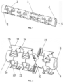
- Fig. 1 is a schematic structural diagram of an intervertebral disc fusion cage when being closed according to an embodiment of the device.
- Fig. 2 is a schematic structural diagram of an intervertebral disc fusion cage after expansion according to an embodiment of the device.
- Fig. 3 is a partial structural schematic diagram of an intervertebral disc fusion cage when being closed according to an embodiment of the device.
- a plurality of support expansion joints 2 which are distributed at intervals and a stabilization expansion joint 3 are arranged on the tubular body 1 in an axial direction and a circumferential direction. After expansion, the expansion joints expand from an initial state shown in Fig. 1 to an expanded state shown in Fig. 2 .
- Each support expansion joint 2 includes a support sheet plate 21.
- the support sheet plate 21 is respectively provided with extended support plates 22 at both ends in a length direction, which increases contact areas with upper and lower end plates and reduces the intensity of pressure on a support surface of the fusion cage, so that the situation that the end plates are broken by the support surface due to small support area and high pressure, resulting in a collapse of an intervertebral space is avoided or reduced.
- each support sheet plate 21 Both sides of the bottom of each support sheet plate 21 are respectively connected to the tubular body 1 by means of deformation support sheets 23.
- the deformation support sheets 23 are in the shape of a thin sheet, have a certain elasticity and can be bent and deformed in the deformation process.
- each deformation support sheet 23 is connected to an inner side of each support sheet plate 21, and the other end of the deformation support sheet 23 is connected to the tubular body 1.
- the number of the support expansion joints 2 in the axial direction of the tubular body 1 is set to be at least two, and specifically, may be set according to the needs of a treatment. When more than two support expansion joints 2 are provided, the individual support expansion joints 2 are aligned with each other, that is, the positions of the support sheet plates 21 on the support expansion joints 2 are the same.
- Each support sheet plate 21 is provided with an inward-bending stopper 25 for limiting deformation of the top ends of the deformation support sheets 23, and each inward-bending stopper 25 and the corresponding support sheet plate 21 are integrally formed.
- An outward-bending stopper 24 for limiting deformation of the bottom ends of the deformation support sheets 23 is arranged between two adjacent support expansion joints 2 on the tubular body 1, and the outward-bending stopper 24 and the tubular body 1 are integrally formed.
- the deformation support sheets 23 are restricted by the inward-bending stoppers 25 and the outward-bending stoppers 24, so that the support sheet plates 21 after expansion are axially parallel to the fusion cage, and a fusion space of the intervertebral space is ensured.
- Two oppositely arranged limit blocks 26 are provided between two adjacent support expansion joints 2 in the circumferential direction of the tubular body 1, and the two limit blocks 26 abut against each other when the deformation support sheets 23 expand to the maximum.
- the two limit blocks 26 abut against each other when the deformation support sheets 23 expand to the maximum, so that excessive expansion of the deformation support sheets 23 can be avoided, and the support sheet plates 21 can be ensured to be axially parallel to the fusion cage.
- a connecting portion is provided between the extended support plates 22 and the inward-bending stopper 25 on each support expansion joint 2.
- the top ends of the deformation support sheets 23 are connected to the corresponding connecting portion.
- Both ends of each inward-bending stopper 25 respectively extend toward the deformation support sheets 23, and both ends of each inward-bending stopper 25 protrude to the outside of the corresponding connecting portion.
- each inward-bending stopper 25 is used to limit the deformation amount of the deformation support sheets 23.
- each outward-bending stopper 24 respectively extend toward the deformation support sheets 23.
- the outer sides of deformation support sheets 23 abut on the outward-bending stopper 24, which can effectively control the expansion state of the fusion cage.
- the stabilization expansion joint 3 includes a plurality of support bars 31 arranged at intervals, and a cavity is left between two connected support bars 31.
- oppositely arranged stop blocks 32 are arranged at both ends of each cavity.
- the two oppositely arranged stop blocks 32 abut against each other.
- four support bars 31 are provided and are uniformly arranged in the circumferential direction of the tubular body 1.
- a positioning groove 4 is formed in one end, connected to a fusion cage placement tool, of the tubular body 1, and the fusion cage is inserted into the positioning groove 4.
- Fig. 4 is a schematic structural diagram of an intervertebral disc fusion cage in the early stage of expansion according to an embodiment of the utility model.
- Fig. 5 is a partial structural schematic diagram of an intervertebral disc fusion cage after expansion according to an embodiment of the device.
- the extended support plate 22 on one side is deformed firstly.
- the extended support plate 22 on the other side is deformed.
- the deformation support sheets 23 expand to the maximum state, the inner sides of the two oppositely arranged deformation support sheets 23 both abut on the inward-bending stopper 25.
- the support bars 31 expand to the maximum, the two oppositely arranged stop blocks 32 abut against each other.
- a pull rod of an expansion tool penetrates through a tubular body inner hole 5.
- each support plate 21 expands to both sides until the limit blocks 26 on both sides are contacted and pressed tightly, and two support sheet plates 21 expand outward to be combined with and support with the end plates of upper and lower vertebral bodies.
- Four support bars 31 on the stabilization expansion joints 3 bulge in four oblique directions when expansion and then are bent until the stop blocks 32 are contacted and compressed.
- the support sheet plates 21 are not parallel to the axis of the tubular body 1.
- the support sheet plates 21 With the axial compression of the fusion cage, the support sheet plates 21 are gradually bent and deformed. Under the restriction of the outward-bending stoppers 24 and the inward-bending stoppers 25, after the support sheet plates 21 on one side reach the limit of bending, the support sheet plates 21 on the other side would continue to be bent and deformed until the support sheet plates 21 on the two sides are in a consistent state.
- each support sheet plate 21 is respectively provided with extended support plates 22 at both ends in the length direction, which increases contact areas with the upper and lower end plates and reduces the intensity of the pressure on a support surface of the fusion cage, so that the situation that the end plates are broken by the support surface due to small support area and high pressure, resulting in a collapse of an intervertebral space is avoided or reduced.
- the deformation support sheets 23 are limited by the inward-bending stoppers 25 and the outward-bending stoppers 24 in the expansion and deformation process, which realizes that the support sheet plates 21 are axially parallel to the fusion cage after expansion, and ensures a fusion space of the intervertebral space.
- Two oppositely arranged limit blocks 26 are provided between two adjacent support expansion joints 2 in the circumferential direction of the tubular body 1.
- the two limit blocks 26 abut against each other, which can avoid excessive expansion of the deformation support sheets 23, and can ensure that the support sheet plates 21 and the fusion cage remain parallel in the axial direction.
- the expansion joints on the tubular body can expand in sequence from inside to outside, and are all in a state of the same expansion size, which can ensure that the expanded contact sheet is in a horizontal state, avoid the ridge-shaped protrusion from being skewed, and maintain a height of the intervertebral space and the stability of the vertebral body, so as not to bring an unnecessary harm to a patient.
Landscapes
- Health & Medical Sciences (AREA)
- Engineering & Computer Science (AREA)
- Biomedical Technology (AREA)
- Neurology (AREA)
- Orthopedic Medicine & Surgery (AREA)
- Cardiology (AREA)
- Oral & Maxillofacial Surgery (AREA)
- Transplantation (AREA)
- Heart & Thoracic Surgery (AREA)
- Vascular Medicine (AREA)
- Life Sciences & Earth Sciences (AREA)
- Animal Behavior & Ethology (AREA)
- General Health & Medical Sciences (AREA)
- Public Health (AREA)
- Veterinary Medicine (AREA)
- Prostheses (AREA)
Description
- The disclosed device relates to the technical field of medical devices, in particular to an intervertebral disc fusion cage.
- An intervertebral disc is divided into nucleus pulposus, which is rich in an elastic jellylike substance, in the central part and annulus fibrosus, which is arranged in concentric circles by multiple layers of fibrocartilage rings, in the peripheral part. The annulus fibrosus in the neck and waist is thick in the front and thin in the back, and the nucleus pulposus is easy to protrude posterolaterally, protruding into a spinal canal or intervertebral foramen and compressing a spinal cord or spinal nerves to form intervertebral disc herniation. In the prior art, intervertebral disc herniation is usually treated by surgically implanting an intervertebral disc fusion cage.
- An original shape of the fusion cage is of a 6 mm columnar structure, and the fusion cage is made of metal titanium, has a high degree of biocompatibility and sturdiness and can be implanted in a diseased intervertebral space through a channel with an outer diameter of 7 mm without too much damage to a vertebral body structure. After being in a proper position in the intervertebral space, the fusion cage expands by rotating a handle of a fusion cage installation tool, and its expansion diameter may reach 15 mm to the maximum. By matching with implantation of autologous or allogeneic bones, a height of the intervertebral space is effectively restored and maintained.
- Chinese utility model patent
CN207506664U discloses an expandable intervertebral fusion cage. By designing an expansion joint with a horizontally arranged contact sheet, and using an expansion sheet to connect the contact sheet with a tubular body of the fusion cage, during a surgical treatment, when the tubular body of the fusion cage is compressed, the expansion sheet bends and expands outward under the action of an external force and drives the contact sheet connected thereto to expand outward at the same time. Since the contact sheet is not directly affected by the external force, the contact sheet may still maintain a horizontal state after compression. Thus, a relatively large contact area may be provided for the vertebral body, the safety during the surgery can be ensured while the height and stability of the intervertebral space are ensured, and an injury to a patient caused by the skew of the expansion joint after compression can be avoided. However, in the expansion process of an actual surgery, due to inconsistency of external pressure and other factors, the expansion degrees of second expansion sheets on both sides of the contact sheet may be inconsistent, and the contact sheet may not be parallel to an axis. With the continuous compression in an axial direction of the fusion cage, the support sheet is bent and deformed, an expansion sequence of the second expansion sheets cannot be determined, and the second expansion sheets may be inclined, thereby causing the expanded contact sheet not to be in a horizontal state, and still causing a ridge-shaped protrusion to be skewed, which makes it difficult to maintain the height of the intervertebral space and the stability of the vertebral body, and still brings an unnecessary harm to the patient. - In view of the existing problems in the prior art that it is difficult to grasp an expansion state of a fusion cage implanted in a main body, an expansion order of second expansion sheets cannot be determined, and the second expansion sheets may be inclined, resulting in a skew of a ridge-shaped protrusion, the device provides an intervertebral disc fusion cage, so as to achieve the beneficial effects of ensuring that the intervertebral disc fusion cage expands in sequence and ensuring a contact sheet to be in a horizontal state after expansion.
- The device provides an intervertebral disc fusion cage, including a tubular body, where a plurality of support expansion joints which are distributed at intervals and a stabilization expansion joint are arranged on the tubular body in an axial direction and a circumferential direction; each support expansion joint includes a support sheet plate; each support sheet plate is respectively provided with extended support plates at both ends in a length direction; both sides of the bottom of each support sheet plate are respectively connected to the tubular body by means of deformation support sheets; each support sheet plate is provided with an inward-bending stopper for limiting deformation of the top ends of the deformation support sheets; an outward-bending stopper for limiting deformation of the bottom ends of the deformation support sheets is arranged between two adjacent support expansion joints on the tubular body; two oppositely arranged limit blocks are provided between the two adjacent support expansion joints in the circumferential direction of the tubular body; and the two limit blocks abut against each other when the deformation support sheets expand to the maximum.
- Further, a connecting portion is provided between the extended support plates and the inward-bending stopper on each support expansion joint; the top ends of the deformation support sheets are connected to the connecting portion; both ends of the inward-bending stopper respectively extend toward the deformation support sheets; and when the deformation support sheets expand to the maximum state, the inner sides of the two oppositely arranged deformation support sheets both abut on the inward-bending stopper.
- Further, both ends of each outward-bending stopper respectively extend toward the deformation support sheets; and when the deformation support sheets expand to the maximum state, the outer sides of deformation support sheets abut on the outward-bending stopper.
- Further, the stabilization expansion joint includes a plurality of support bars arranged at intervals; a cavity is left between two connected support bars; oppositely arranged stop blocks are arranged at both ends of each cavity; and when the support bars expand to the maximum, the two oppositely arranged stop blocks abut against each other.
- Further, a positioning groove is formed in one end, connected to a fusion cage placement tool, of the tubular body.
- Further, four support bars are provided and are uniformly arranged in the circumferential direction of the tubular body.
- The device has the beneficial effects as follows:
In the intervertebral disc fusion cage provided by the device each support sheet plate is respectively provided with the extended support plates at both ends in the length direction, which increases contact areas with upper and lower end plates and reduces the intensity of pressure on a support surface of the fusion cage, so that the situation that the end plates are broken by the support surface due to small support area and high pressure, resulting in a collapse of an intervertebral space is avoided or reduced. The deformation support sheets are limited by the inward-bending stoppers and the outward-bending stoppers in the expansion and deformation process, which realizes that the support sheet plates are axially parallel to the fusion cage after expansion, and ensures a fusion space of the intervertebral space. The two oppositely arranged limit blocks are provided between two adjacent support expansion joints in the circumferential direction of the tubular body, and when the deformation support sheets expand to the maximum, the two limit blocks abut against each other, so that excessive expansion of the deformation support sheets can be avoided, and the support sheet plates can be ensured to keep parallel to the fusion cage in the axial direction. By changing the size of the support sheet plates, multiple specifications of opening sizes may be obtained, and thus the clinical needs of a variety of sizes can be met. According to the intervertebral disc fusion cage provided by the device the expansion joints on the tubular body can expand in sequence from inside to outside and are all in a state of the same expansion size, which can ensure that the expanded contact sheet is in a horizontal state, avoid the ridge-shaped protrusion from being skewed, and maintain the height of the intervertebral space and the stability of the vertebral body, so as not to bring an unnecessary harm to a patient. - In addition, the device is reliable in design principle and simple in structure, and has a very wide application prospect.
- In order to more clearly illustrate the embodiments of the device or the technical solutions in the prior art, the accompanying drawings that need to be used in the embodiments or the prior art will be briefly described below. Obviously, a person of ordinary skill in the art may also obtain other drawings based on these drawings without creative effort.
-
Fig. 1 is a schematic structural diagram of an intervertebral disc fusion cage when being closed according to an embodiment of the utility device. -
Fig. 2 is a schematic structural diagram of an intervertebral disc fusion cage after expansion according to an embodiment of the device. -
Fig. 3 is a partial structural schematic diagram of an intervertebral disc fusion cage when being closed according to an embodiment of the device. -
Fig. 4 is a schematic structural diagram of an intervertebral disc fusion cage in the early stage of expansion according to an embodiment of the device. -
Fig. 5 is a partial structural schematic diagram of an intervertebral disc fusion cage after expansion according to an embodiment of the device. - In the drawings, 1, tubular body; 2, support expansion joint; 21, support sheet plate; 22, extended support plate; 23, deformation support sheet; 24, outward-bending stopper; 25, inward-bending stopper; 26, limit block; 3, stabilization expansion joint; 31, support bar; 32, stop block; 4, positioning groove; 5, tubular body inner hole.
- In order to make those skilled in the art better understand the technical solutions in the device the technical solutions in the embodiments of the device will be clearly and completely described as below with reference to the accompanying drawings in the embodiments of the device. Obviously, the described embodiments are only a part of, not all of, the embodiments of the device. All other embodiments obtained by a person of ordinary skill in the art based on the embodiments of the device without creative effort shall fall within the protection scope of the utility model.
- Key terms appearing in the device are explained below.
- An intervertebral disc fusion cage provided by the utility model includes a
tubular body 1. -
Fig. 1 is a schematic structural diagram of an intervertebral disc fusion cage when being closed according to an embodiment of the device.Fig. 2 is a schematic structural diagram of an intervertebral disc fusion cage after expansion according to an embodiment of the device.Fig. 3 is a partial structural schematic diagram of an intervertebral disc fusion cage when being closed according to an embodiment of the device. As shown inFigs. 1-3 , a plurality ofsupport expansion joints 2 which are distributed at intervals and astabilization expansion joint 3 are arranged on thetubular body 1 in an axial direction and a circumferential direction. After expansion, the expansion joints expand from an initial state shown inFig. 1 to an expanded state shown inFig. 2 . - Each
support expansion joint 2 includes asupport sheet plate 21. Thesupport sheet plate 21 is respectively provided withextended support plates 22 at both ends in a length direction, which increases contact areas with upper and lower end plates and reduces the intensity of pressure on a support surface of the fusion cage, so that the situation that the end plates are broken by the support surface due to small support area and high pressure, resulting in a collapse of an intervertebral space is avoided or reduced. - Both sides of the bottom of each
support sheet plate 21 are respectively connected to thetubular body 1 by means ofdeformation support sheets 23. Thedeformation support sheets 23 are in the shape of a thin sheet, have a certain elasticity and can be bent and deformed in the deformation process. - One end of each
deformation support sheet 23 is connected to an inner side of eachsupport sheet plate 21, and the other end of thedeformation support sheet 23 is connected to thetubular body 1. - The number of the
support expansion joints 2 in the axial direction of thetubular body 1 is set to be at least two, and specifically, may be set according to the needs of a treatment. When more than twosupport expansion joints 2 are provided, the individualsupport expansion joints 2 are aligned with each other, that is, the positions of thesupport sheet plates 21 on thesupport expansion joints 2 are the same. - Each
support sheet plate 21 is provided with an inward-bending stopper 25 for limiting deformation of the top ends of thedeformation support sheets 23, and each inward-bending stopper 25 and the correspondingsupport sheet plate 21 are integrally formed. An outward-bending stopper 24 for limiting deformation of the bottom ends of thedeformation support sheets 23 is arranged between two adjacentsupport expansion joints 2 on thetubular body 1, and the outward-bending stopper 24 and thetubular body 1 are integrally formed. - In the process of expansion and deformation, the
deformation support sheets 23 are restricted by the inward-bending stoppers 25 and the outward-bending stoppers 24, so that thesupport sheet plates 21 after expansion are axially parallel to the fusion cage, and a fusion space of the intervertebral space is ensured. - Two oppositely arranged
limit blocks 26 are provided between two adjacentsupport expansion joints 2 in the circumferential direction of thetubular body 1, and the two limit blocks 26 abut against each other when thedeformation support sheets 23 expand to the maximum. - The two limit blocks 26 abut against each other when the
deformation support sheets 23 expand to the maximum, so that excessive expansion of thedeformation support sheets 23 can be avoided, and thesupport sheet plates 21 can be ensured to be axially parallel to the fusion cage. - A connecting portion is provided between the
extended support plates 22 and the inward-bending stopper 25 on eachsupport expansion joint 2. The top ends of thedeformation support sheets 23 are connected to the corresponding connecting portion. Both ends of each inward-bending stopper 25 respectively extend toward thedeformation support sheets 23, and both ends of each inward-bending stopper 25 protrude to the outside of the corresponding connecting portion. - When the
deformation support sheets 23 expand to the maximum state, the inner sides of the two oppositely arrangeddeformation support sheets 23 both abut on each inward-bendingstopper 25. Each inward-bendingstopper 25 is used to limit the deformation amount of thedeformation support sheets 23. - Both ends of each outward-bending
stopper 24 respectively extend toward thedeformation support sheets 23. When thedeformation support sheets 23 expand to the maximum state, the outer sides ofdeformation support sheets 23 abut on the outward-bendingstopper 24, which can effectively control the expansion state of the fusion cage. - The
stabilization expansion joint 3 includes a plurality of support bars 31 arranged at intervals, and a cavity is left between two connected support bars 31. - In order to keep the expansion state of the fusion cage unchanged, oppositely arranged stop blocks 32 are arranged at both ends of each cavity. When the support bars 31 expand to the maximum, the two oppositely arranged stop blocks 32 abut against each other.
- In this embodiment, four
support bars 31 are provided and are uniformly arranged in the circumferential direction of thetubular body 1. - A positioning groove 4 is formed in one end, connected to a fusion cage placement tool, of the
tubular body 1, and the fusion cage is inserted into the positioning groove 4. -
Fig. 4 is a schematic structural diagram of an intervertebral disc fusion cage in the early stage of expansion according to an embodiment of the utility model.Fig. 5 is a partial structural schematic diagram of an intervertebral disc fusion cage after expansion according to an embodiment of the device. As shown inFig. 4 , in the early stage of expansion of the intervertebral disc fusion cage, theextended support plate 22 on one side is deformed firstly. After the fusion cage is continuously compressed, theextended support plate 22 on the other side is deformed. When thedeformation support sheets 23 expand to the maximum state, the inner sides of the two oppositely arrangeddeformation support sheets 23 both abut on the inward-bendingstopper 25. When the support bars 31 expand to the maximum, the two oppositely arranged stop blocks 32 abut against each other. - The implementation of this embodiment is that:
A pull rod of an expansion tool penetrates through a tubular bodyinner hole 5. When the pull rod makes a pull and a pressure in the axial direction, eachsupport plate 21 expands to both sides until the limit blocks 26 on both sides are contacted and pressed tightly, and twosupport sheet plates 21 expand outward to be combined with and support with the end plates of upper and lower vertebral bodies. Four support bars 31 on thestabilization expansion joints 3 bulge in four oblique directions when expansion and then are bent until the stop blocks 32 are contacted and compressed. In the expansion process, due to inconsistency of external pressure and other factors, there may be cases where expansion of both sides of thesupport expansion joints 2 is inconsistent, and thesupport sheet plates 21 are not parallel to the axis of thetubular body 1. With the axial compression of the fusion cage, thesupport sheet plates 21 are gradually bent and deformed. Under the restriction of the outward-bendingstoppers 24 and the inward-bendingstoppers 25, after thesupport sheet plates 21 on one side reach the limit of bending, thesupport sheet plates 21 on the other side would continue to be bent and deformed until thesupport sheet plates 21 on the two sides are in a consistent state. - In the intervertebral disc fusion cage provided by the device each
support sheet plate 21 is respectively provided withextended support plates 22 at both ends in the length direction, which increases contact areas with the upper and lower end plates and reduces the intensity of the pressure on a support surface of the fusion cage, so that the situation that the end plates are broken by the support surface due to small support area and high pressure, resulting in a collapse of an intervertebral space is avoided or reduced. Thedeformation support sheets 23 are limited by the inward-bendingstoppers 25 and the outward-bendingstoppers 24 in the expansion and deformation process, which realizes that thesupport sheet plates 21 are axially parallel to the fusion cage after expansion, and ensures a fusion space of the intervertebral space. Two oppositely arranged limit blocks 26 are provided between two adjacentsupport expansion joints 2 in the circumferential direction of thetubular body 1. When thedeformation support sheets 23 expand to the maximum, the two limit blocks 26 abut against each other, which can avoid excessive expansion of thedeformation support sheets 23, and can ensure that thesupport sheet plates 21 and the fusion cage remain parallel in the axial direction. By changing the size of thesupport sheet plates 21, multiple specifications of opening sizes can be obtained to meet the clinical needs of a variety of sizes. According to the intervertebral disc fusion cage provided by the device, the expansion joints on the tubular body can expand in sequence from inside to outside, and are all in a state of the same expansion size, which can ensure that the expanded contact sheet is in a horizontal state, avoid the ridge-shaped protrusion from being skewed, and maintain a height of the intervertebral space and the stability of the vertebral body, so as not to bring an unnecessary harm to a patient. - Although the device has been described in detail with reference to the accompanying drawings and in conjunction with the preferred embodiments, those of ordinary skill in the art can make various equivalent modifications or replacements to the embodiments of the device.
Claims (6)
- An intervertebral disc fusion cage, comprising a tubular body (1), wherein a plurality of support expansion joints (2) which are distributed at intervals and a stabilization expansion joint (3) are arranged on the tubular body in an axial direction and a circumferential direction; each support expansion joint (2) comprises a support sheet plate (21); each support sheet plate (21) is respectively provided with extended support plates (22) at both ends in a length direction; both sides of the bottom of each support sheet plate (21) are connected to the tubular body (1) by means of deformation support sheets (23) respectively; each support sheet plate (21) is provided with an inward-bending stopper (25) for limiting deformation of the top ends of the deformation support sheets (23); an outward-bending stopper (24) for limiting deformation of the bottom ends of the deformation support sheets (23) is arranged between two adjacent support expansion joints (2) on the tubular body; two oppositely arranged limit blocks (26) are provided between two adjacent support expansion joints (2) in the circumferential direction of the tubular body (1); and the two limit blocks (26) abut against each other when the deformation support sheets (23) expand to the maximum.
- The intervertebral disc fusion cage according to claim 1, characterized in that a connecting portion is provided between the extended support plates (22) and the inward-bending stopper (25) on each support expansion joint (2); the top ends of the deformation support sheets (23) are connected to the connecting portion; both ends of the inward-bending stopper (25) respectively extend toward the deformation support sheets (23); and when the deformation support sheets (23) expand to the maximum state, the inner sides of the two oppositely arranged deformation support sheets (23) both abut on the inward-bending stopper (25).
- The intervertebral disc fusion cage according to claim 1, characterized in that both ends of each outward-bending stopper (24) respectively extend toward the deformation support sheets (23); and when the deformation support sheets (23) expand to the maximum state, the outer sides of deformation support sheets (23) abut on the outward-bending stopper (24).
- The intervertebral disc fusion cage according to claim 1, characterized in that the stabilization expansion joint (3) comprises a plurality of support bars (31) arranged at intervals; a cavity is left between two connected support bars (31); oppositely arranged stop blocks (32) are arranged at both ends of each cavity; and when the support bars (31) expand to the maximum, the two oppositely arranged stop blocks (32) abut against each other.
- The intervertebral disc fusion cage according to claim 1, characterized in that a positioning groove (4) is formed in one end, connected to a fusion cage placement tool, of the tubular body (1).
- The intervertebral disc fusion cage according to claim 4, characterized in that four support bars (31) are provided and are uniformly arranged in the circumferential direction of the tubular body (1).
Applications Claiming Priority (2)
| Application Number | Priority Date | Filing Date | Title |
|---|---|---|---|
| CN202020281213.7U CN212234811U (en) | 2020-03-09 | 2020-03-09 | Intervertebral disc fusion device |
| PCT/CN2020/124584 WO2021179628A1 (en) | 2020-03-09 | 2020-10-29 | Intervertebral disc fusion cage |
Publications (3)
| Publication Number | Publication Date |
|---|---|
| EP4112012A1 EP4112012A1 (en) | 2023-01-04 |
| EP4112012A4 EP4112012A4 (en) | 2023-08-23 |
| EP4112012B1 true EP4112012B1 (en) | 2024-05-01 |
Family
ID=73991005
Family Applications (1)
| Application Number | Title | Priority Date | Filing Date |
|---|---|---|---|
| EP20924042.3A Active EP4112012B1 (en) | 2020-03-09 | 2020-10-29 | Intervertebral disc fusion cage |
Country Status (7)
| Country | Link |
|---|---|
| EP (1) | EP4112012B1 (en) |
| JP (1) | JP7410325B2 (en) |
| KR (1) | KR102757754B1 (en) |
| CN (1) | CN212234811U (en) |
| ES (1) | ES2985918T3 (en) |
| PT (1) | PT4112012T (en) |
| WO (1) | WO2021179628A1 (en) |
Family Cites Families (13)
| Publication number | Priority date | Publication date | Assignee | Title |
|---|---|---|---|---|
| EP1675533A2 (en) | 2003-09-19 | 2006-07-05 | Synecor, LLC | Method and apparatus for treating diseased or fractured bone |
| FR2871366A1 (en) | 2004-06-09 | 2005-12-16 | Ceravic Soc Par Actions Simpli | PROSTHETIC EXPANSIBLE BONE IMPLANT |
| US7799056B2 (en) * | 2007-12-31 | 2010-09-21 | Warsaw Orthopedic, Inc. | Bone fusion device and methods |
| PL2405835T3 (en) | 2009-03-12 | 2018-05-30 | Vexim | Apparatus for bone restoration of the spine |
| CN102599994A (en) * | 2011-01-22 | 2012-07-25 | 张春霖 | Contact-surface wave-changing bridge arc type interbody cage |
| JP5916838B2 (en) | 2011-03-23 | 2016-05-11 | アルファテック スパイン, インコーポレイテッド | Extendable interbody spacer |
| EP2777632B1 (en) | 2013-03-15 | 2020-04-22 | Howmedica Osteonics Corp. | Adjustable distraction cage with linked locking mechanisms. |
| CN203341866U (en) * | 2013-03-19 | 2013-12-18 | 中国人民解放军第二军医大学 | Interbody fusion cage with expandable lumbar |
| US9421110B2 (en) * | 2013-05-10 | 2016-08-23 | Sidewinder Medical Products Llc | Expandable spinal fusion cage |
| CN106618811B (en) * | 2017-02-22 | 2019-01-29 | 无锡宝莱福医疗器械有限公司 | A kind of function bionics type cervical artificial disc |
| CN207506664U (en) | 2017-04-18 | 2018-06-19 | 山东冠龙医疗用品有限公司 | A kind of intervertebral may expand fusion device |
| CN108113782B (en) * | 2017-12-12 | 2020-07-03 | 中以医疗技术发展有限公司 | Vertebral body fusion cage |
| US10869769B2 (en) | 2018-03-06 | 2020-12-22 | Eit Emerging Implant Technologies Gmbh | Intervertebral cages with integrated expansion and angular adjustment mechanism |
-
2020
- 2020-03-09 CN CN202020281213.7U patent/CN212234811U/en active Active
- 2020-10-29 EP EP20924042.3A patent/EP4112012B1/en active Active
- 2020-10-29 WO PCT/CN2020/124584 patent/WO2021179628A1/en not_active Ceased
- 2020-10-29 ES ES20924042T patent/ES2985918T3/en active Active
- 2020-10-29 PT PT209240423T patent/PT4112012T/en unknown
- 2020-10-29 KR KR1020227032698A patent/KR102757754B1/en active Active
- 2020-10-29 JP JP2022554183A patent/JP7410325B2/en active Active
Also Published As
| Publication number | Publication date |
|---|---|
| JP2023517210A (en) | 2023-04-24 |
| KR20230002328A (en) | 2023-01-05 |
| JP7410325B2 (en) | 2024-01-09 |
| PT4112012T (en) | 2024-07-10 |
| WO2021179628A1 (en) | 2021-09-16 |
| CN212234811U (en) | 2020-12-29 |
| ES2985918T3 (en) | 2024-11-07 |
| EP4112012A1 (en) | 2023-01-04 |
| KR102757754B1 (en) | 2025-01-22 |
| EP4112012A4 (en) | 2023-08-23 |
Similar Documents
| Publication | Publication Date | Title |
|---|---|---|
| JP6532519B2 (en) | Bilateral interbody fusion device | |
| EP3528724B1 (en) | Interbody spacer for spinal fusion | |
| US10369004B2 (en) | Expandable intervertebralspacer | |
| JP4197845B2 (en) | Expandable intervertebral spacer | |
| EP2234564B1 (en) | Intervertebral cage and vertebral fusion device | |
| US9566167B2 (en) | Expandable spinal implant | |
| CN103876865B (en) | Inflatable Invasive lumbar fusion device | |
| US20060276899A1 (en) | Minimally invasive apparatus to manipulate and revitalize spinal column disc | |
| US20060276901A1 (en) | Minimally invasive apparatus to manipulate and revitalize spinal column disc | |
| CN107865714A (en) | Expandable Intervertebral Fusion Implant | |
| CN102427769A (en) | Apparatus for bone restoration of the spine and methods of use | |
| EP4112012A1 (en) | Intervertebral disc fusion cage | |
| CN108113781B (en) | Height-adjustable threaded fusion cage | |
| JP3909323B2 (en) | Inflatable osteosynthesis cage | |
| CN212679345U (en) | interbody cage | |
| CN108113782B (en) | Vertebral body fusion cage | |
| CN115381606A (en) | Angle-expandable intervertebral fusion cage and spine implantation system thereof | |
| US11497615B2 (en) | Cervical disc and instrumentation | |
| CN111134913B (en) | Interbody Fusion Cage | |
| CN209499987U (en) | Intervertebral Fusion | |
| CN112089509B (en) | An integrated interbody treatment cage | |
| US9504501B2 (en) | Systems and methods for reducing pressure within a spinal disc | |
| US20100249932A1 (en) | Materials, Devices and Methods for Intervertebral Stabilization Via Use of In Situ Shape Recovery | |
| CN223453354U (en) | Interbody fusion cage | |
| US20230000638A1 (en) | Cage for minimal invasive surgery |
Legal Events
| Date | Code | Title | Description |
|---|---|---|---|
| STAA | Information on the status of an ep patent application or granted ep patent |
Free format text: STATUS: THE INTERNATIONAL PUBLICATION HAS BEEN MADE |
|
| PUAI | Public reference made under article 153(3) epc to a published international application that has entered the european phase |
Free format text: ORIGINAL CODE: 0009012 |
|
| STAA | Information on the status of an ep patent application or granted ep patent |
Free format text: STATUS: REQUEST FOR EXAMINATION WAS MADE |
|
| 17P | Request for examination filed |
Effective date: 20220930 |
|
| AK | Designated contracting states |
Kind code of ref document: A1 Designated state(s): AL AT BE BG CH CY CZ DE DK EE ES FI FR GB GR HR HU IE IS IT LI LT LU LV MC MK MT NL NO PL PT RO RS SE SI SK SM TR |
|
| DAV | Request for validation of the european patent (deleted) | ||
| DAX | Request for extension of the european patent (deleted) | ||
| A4 | Supplementary search report drawn up and despatched |
Effective date: 20230720 |
|
| RIC1 | Information provided on ipc code assigned before grant |
Ipc: A61F 2/30 20060101ALI20230714BHEP Ipc: A61F 2/44 20060101AFI20230714BHEP |
|
| GRAP | Despatch of communication of intention to grant a patent |
Free format text: ORIGINAL CODE: EPIDOSNIGR1 |
|
| STAA | Information on the status of an ep patent application or granted ep patent |
Free format text: STATUS: GRANT OF PATENT IS INTENDED |
|
| INTG | Intention to grant announced |
Effective date: 20240124 |
|
| GRAS | Grant fee paid |
Free format text: ORIGINAL CODE: EPIDOSNIGR3 |
|
| GRAA | (expected) grant |
Free format text: ORIGINAL CODE: 0009210 |
|
| STAA | Information on the status of an ep patent application or granted ep patent |
Free format text: STATUS: THE PATENT HAS BEEN GRANTED |
|
| AK | Designated contracting states |
Kind code of ref document: B1 Designated state(s): AL AT BE BG CH CY CZ DE DK EE ES FI FR GB GR HR HU IE IS IT LI LT LU LV MC MK MT NL NO PL PT RO RS SE SI SK SM TR |
|
| REG | Reference to a national code |
Ref country code: GB Ref legal event code: FG4D |
|
| REG | Reference to a national code |
Ref country code: CH Ref legal event code: EP |
|
| REG | Reference to a national code |
Ref country code: IE Ref legal event code: FG4D |
|
| REG | Reference to a national code |
Ref country code: DE Ref legal event code: R096 Ref document number: 602020030443 Country of ref document: DE |
|
| REG | Reference to a national code |
Ref country code: PT Ref legal event code: SC4A Ref document number: 4112012 Country of ref document: PT Date of ref document: 20240710 Kind code of ref document: T Free format text: AVAILABILITY OF NATIONAL TRANSLATION Effective date: 20240705 |
|
| REG | Reference to a national code |
Ref country code: NL Ref legal event code: FP |
|
| REG | Reference to a national code |
Ref country code: LT Ref legal event code: MG9D |
|
| PG25 | Lapsed in a contracting state [announced via postgrant information from national office to epo] |
Ref country code: IS Free format text: LAPSE BECAUSE OF FAILURE TO SUBMIT A TRANSLATION OF THE DESCRIPTION OR TO PAY THE FEE WITHIN THE PRESCRIBED TIME-LIMIT Effective date: 20240901 |
|
| PG25 | Lapsed in a contracting state [announced via postgrant information from national office to epo] |
Ref country code: BG Free format text: LAPSE BECAUSE OF FAILURE TO SUBMIT A TRANSLATION OF THE DESCRIPTION OR TO PAY THE FEE WITHIN THE PRESCRIBED TIME-LIMIT Effective date: 20240501 |
|
| PG25 | Lapsed in a contracting state [announced via postgrant information from national office to epo] |
Ref country code: FI Free format text: LAPSE BECAUSE OF FAILURE TO SUBMIT A TRANSLATION OF THE DESCRIPTION OR TO PAY THE FEE WITHIN THE PRESCRIBED TIME-LIMIT Effective date: 20240501 Ref country code: HR Free format text: LAPSE BECAUSE OF FAILURE TO SUBMIT A TRANSLATION OF THE DESCRIPTION OR TO PAY THE FEE WITHIN THE PRESCRIBED TIME-LIMIT Effective date: 20240501 |
|
| PG25 | Lapsed in a contracting state [announced via postgrant information from national office to epo] |
Ref country code: GR Free format text: LAPSE BECAUSE OF FAILURE TO SUBMIT A TRANSLATION OF THE DESCRIPTION OR TO PAY THE FEE WITHIN THE PRESCRIBED TIME-LIMIT Effective date: 20240802 |
|
| REG | Reference to a national code |
Ref country code: AT Ref legal event code: MK05 Ref document number: 1681358 Country of ref document: AT Kind code of ref document: T Effective date: 20240501 |
|
| PG25 | Lapsed in a contracting state [announced via postgrant information from national office to epo] |
Ref country code: AT Free format text: LAPSE BECAUSE OF FAILURE TO SUBMIT A TRANSLATION OF THE DESCRIPTION OR TO PAY THE FEE WITHIN THE PRESCRIBED TIME-LIMIT Effective date: 20240501 |
|
| PG25 | Lapsed in a contracting state [announced via postgrant information from national office to epo] |
Ref country code: PL Free format text: LAPSE BECAUSE OF FAILURE TO SUBMIT A TRANSLATION OF THE DESCRIPTION OR TO PAY THE FEE WITHIN THE PRESCRIBED TIME-LIMIT Effective date: 20240501 |
|
| PG25 | Lapsed in a contracting state [announced via postgrant information from national office to epo] |
Ref country code: LV Free format text: LAPSE BECAUSE OF FAILURE TO SUBMIT A TRANSLATION OF THE DESCRIPTION OR TO PAY THE FEE WITHIN THE PRESCRIBED TIME-LIMIT Effective date: 20240501 |
|
| PG25 | Lapsed in a contracting state [announced via postgrant information from national office to epo] |
Ref country code: PL Free format text: LAPSE BECAUSE OF FAILURE TO SUBMIT A TRANSLATION OF THE DESCRIPTION OR TO PAY THE FEE WITHIN THE PRESCRIBED TIME-LIMIT Effective date: 20240501 Ref country code: NO Free format text: LAPSE BECAUSE OF FAILURE TO SUBMIT A TRANSLATION OF THE DESCRIPTION OR TO PAY THE FEE WITHIN THE PRESCRIBED TIME-LIMIT Effective date: 20240801 Ref country code: LV Free format text: LAPSE BECAUSE OF FAILURE TO SUBMIT A TRANSLATION OF THE DESCRIPTION OR TO PAY THE FEE WITHIN THE PRESCRIBED TIME-LIMIT Effective date: 20240501 Ref country code: IS Free format text: LAPSE BECAUSE OF FAILURE TO SUBMIT A TRANSLATION OF THE DESCRIPTION OR TO PAY THE FEE WITHIN THE PRESCRIBED TIME-LIMIT Effective date: 20240901 Ref country code: HR Free format text: LAPSE BECAUSE OF FAILURE TO SUBMIT A TRANSLATION OF THE DESCRIPTION OR TO PAY THE FEE WITHIN THE PRESCRIBED TIME-LIMIT Effective date: 20240501 Ref country code: GR Free format text: LAPSE BECAUSE OF FAILURE TO SUBMIT A TRANSLATION OF THE DESCRIPTION OR TO PAY THE FEE WITHIN THE PRESCRIBED TIME-LIMIT Effective date: 20240802 Ref country code: FI Free format text: LAPSE BECAUSE OF FAILURE TO SUBMIT A TRANSLATION OF THE DESCRIPTION OR TO PAY THE FEE WITHIN THE PRESCRIBED TIME-LIMIT Effective date: 20240501 Ref country code: BG Free format text: LAPSE BECAUSE OF FAILURE TO SUBMIT A TRANSLATION OF THE DESCRIPTION OR TO PAY THE FEE WITHIN THE PRESCRIBED TIME-LIMIT Effective date: 20240501 Ref country code: AT Free format text: LAPSE BECAUSE OF FAILURE TO SUBMIT A TRANSLATION OF THE DESCRIPTION OR TO PAY THE FEE WITHIN THE PRESCRIBED TIME-LIMIT Effective date: 20240501 Ref country code: RS Free format text: LAPSE BECAUSE OF FAILURE TO SUBMIT A TRANSLATION OF THE DESCRIPTION OR TO PAY THE FEE WITHIN THE PRESCRIBED TIME-LIMIT Effective date: 20240801 |
|
| REG | Reference to a national code |
Ref country code: ES Ref legal event code: FG2A Ref document number: 2985918 Country of ref document: ES Kind code of ref document: T3 Effective date: 20241107 |
|
| PG25 | Lapsed in a contracting state [announced via postgrant information from national office to epo] |
Ref country code: DK Free format text: LAPSE BECAUSE OF FAILURE TO SUBMIT A TRANSLATION OF THE DESCRIPTION OR TO PAY THE FEE WITHIN THE PRESCRIBED TIME-LIMIT Effective date: 20240501 |
|
| PG25 | Lapsed in a contracting state [announced via postgrant information from national office to epo] |
Ref country code: EE Free format text: LAPSE BECAUSE OF FAILURE TO SUBMIT A TRANSLATION OF THE DESCRIPTION OR TO PAY THE FEE WITHIN THE PRESCRIBED TIME-LIMIT Effective date: 20240501 |
|
| PG25 | Lapsed in a contracting state [announced via postgrant information from national office to epo] |
Ref country code: SK Free format text: LAPSE BECAUSE OF FAILURE TO SUBMIT A TRANSLATION OF THE DESCRIPTION OR TO PAY THE FEE WITHIN THE PRESCRIBED TIME-LIMIT Effective date: 20240501 Ref country code: RO Free format text: LAPSE BECAUSE OF FAILURE TO SUBMIT A TRANSLATION OF THE DESCRIPTION OR TO PAY THE FEE WITHIN THE PRESCRIBED TIME-LIMIT Effective date: 20240501 |
|
| PG25 | Lapsed in a contracting state [announced via postgrant information from national office to epo] |
Ref country code: SM Free format text: LAPSE BECAUSE OF FAILURE TO SUBMIT A TRANSLATION OF THE DESCRIPTION OR TO PAY THE FEE WITHIN THE PRESCRIBED TIME-LIMIT Effective date: 20240501 |
|
| PG25 | Lapsed in a contracting state [announced via postgrant information from national office to epo] |
Ref country code: SM Free format text: LAPSE BECAUSE OF FAILURE TO SUBMIT A TRANSLATION OF THE DESCRIPTION OR TO PAY THE FEE WITHIN THE PRESCRIBED TIME-LIMIT Effective date: 20240501 Ref country code: SK Free format text: LAPSE BECAUSE OF FAILURE TO SUBMIT A TRANSLATION OF THE DESCRIPTION OR TO PAY THE FEE WITHIN THE PRESCRIBED TIME-LIMIT Effective date: 20240501 Ref country code: RO Free format text: LAPSE BECAUSE OF FAILURE TO SUBMIT A TRANSLATION OF THE DESCRIPTION OR TO PAY THE FEE WITHIN THE PRESCRIBED TIME-LIMIT Effective date: 20240501 Ref country code: EE Free format text: LAPSE BECAUSE OF FAILURE TO SUBMIT A TRANSLATION OF THE DESCRIPTION OR TO PAY THE FEE WITHIN THE PRESCRIBED TIME-LIMIT Effective date: 20240501 Ref country code: DK Free format text: LAPSE BECAUSE OF FAILURE TO SUBMIT A TRANSLATION OF THE DESCRIPTION OR TO PAY THE FEE WITHIN THE PRESCRIBED TIME-LIMIT Effective date: 20240501 |
|
| REG | Reference to a national code |
Ref country code: DE Ref legal event code: R097 Ref document number: 602020030443 Country of ref document: DE |
|
| PLBE | No opposition filed within time limit |
Free format text: ORIGINAL CODE: 0009261 |
|
| STAA | Information on the status of an ep patent application or granted ep patent |
Free format text: STATUS: NO OPPOSITION FILED WITHIN TIME LIMIT |
|
| 26N | No opposition filed |
Effective date: 20250204 |
|
| PG25 | Lapsed in a contracting state [announced via postgrant information from national office to epo] |
Ref country code: SI Free format text: LAPSE BECAUSE OF FAILURE TO SUBMIT A TRANSLATION OF THE DESCRIPTION OR TO PAY THE FEE WITHIN THE PRESCRIBED TIME-LIMIT Effective date: 20240501 |
|
| PG25 | Lapsed in a contracting state [announced via postgrant information from national office to epo] |
Ref country code: MC Free format text: LAPSE BECAUSE OF FAILURE TO SUBMIT A TRANSLATION OF THE DESCRIPTION OR TO PAY THE FEE WITHIN THE PRESCRIBED TIME-LIMIT Effective date: 20240501 |
|
| PG25 | Lapsed in a contracting state [announced via postgrant information from national office to epo] |
Ref country code: LU Free format text: LAPSE BECAUSE OF NON-PAYMENT OF DUE FEES Effective date: 20241029 Ref country code: BE Free format text: LAPSE BECAUSE OF NON-PAYMENT OF DUE FEES Effective date: 20241031 |
|
| REG | Reference to a national code |
Ref country code: BE Ref legal event code: MM Effective date: 20241031 |
|
| PG25 | Lapsed in a contracting state [announced via postgrant information from national office to epo] |
Ref country code: SE Free format text: LAPSE BECAUSE OF FAILURE TO SUBMIT A TRANSLATION OF THE DESCRIPTION OR TO PAY THE FEE WITHIN THE PRESCRIBED TIME-LIMIT Effective date: 20240501 |
|
| REG | Reference to a national code |
Ref country code: CH Ref legal event code: U11 Free format text: ST27 STATUS EVENT CODE: U-0-0-U10-U11 (AS PROVIDED BY THE NATIONAL OFFICE) Effective date: 20251101 |
|
| PGFP | Annual fee paid to national office [announced via postgrant information from national office to epo] |
Ref country code: NL Payment date: 20251023 Year of fee payment: 6 |
|
| PGFP | Annual fee paid to national office [announced via postgrant information from national office to epo] |
Ref country code: PT Payment date: 20251016 Year of fee payment: 6 |
|
| PGFP | Annual fee paid to national office [announced via postgrant information from national office to epo] |
Ref country code: DE Payment date: 20250911 Year of fee payment: 6 |
|
| PGFP | Annual fee paid to national office [announced via postgrant information from national office to epo] |
Ref country code: GB Payment date: 20251024 Year of fee payment: 6 |
|
| PGFP | Annual fee paid to national office [announced via postgrant information from national office to epo] |
Ref country code: IT Payment date: 20251031 Year of fee payment: 6 |
|
| PGFP | Annual fee paid to national office [announced via postgrant information from national office to epo] |
Ref country code: FR Payment date: 20251029 Year of fee payment: 6 |
|
| PGFP | Annual fee paid to national office [announced via postgrant information from national office to epo] |
Ref country code: TR Payment date: 20251024 Year of fee payment: 6 |
|
| PGFP | Annual fee paid to national office [announced via postgrant information from national office to epo] |
Ref country code: CH Payment date: 20251101 Year of fee payment: 6 |
|
| PGFP | Annual fee paid to national office [announced via postgrant information from national office to epo] |
Ref country code: IE Payment date: 20251021 Year of fee payment: 6 Ref country code: CZ Payment date: 20251017 Year of fee payment: 6 |
|
| PGFP | Annual fee paid to national office [announced via postgrant information from national office to epo] |
Ref country code: ES Payment date: 20251114 Year of fee payment: 6 |
|
| PG25 | Lapsed in a contracting state [announced via postgrant information from national office to epo] |
Ref country code: HU Free format text: LAPSE BECAUSE OF FAILURE TO SUBMIT A TRANSLATION OF THE DESCRIPTION OR TO PAY THE FEE WITHIN THE PRESCRIBED TIME-LIMIT; INVALID AB INITIO Effective date: 20201029 |
|
| PG25 | Lapsed in a contracting state [announced via postgrant information from national office to epo] |
Ref country code: CY Free format text: LAPSE BECAUSE OF FAILURE TO SUBMIT A TRANSLATION OF THE DESCRIPTION OR TO PAY THE FEE WITHIN THE PRESCRIBED TIME-LIMIT; INVALID AB INITIO Effective date: 20201029 |
|
| PG25 | Lapsed in a contracting state [announced via postgrant information from national office to epo] |
Ref country code: LT Free format text: LAPSE BECAUSE OF FAILURE TO SUBMIT A TRANSLATION OF THE DESCRIPTION OR TO PAY THE FEE WITHIN THE PRESCRIBED TIME-LIMIT Effective date: 20240501 |