EP4111884A1 - Aerosol generating device and electromagnetic heating assembly thereof - Google Patents
Aerosol generating device and electromagnetic heating assembly thereof Download PDFInfo
- Publication number
- EP4111884A1 EP4111884A1 EP21776842.3A EP21776842A EP4111884A1 EP 4111884 A1 EP4111884 A1 EP 4111884A1 EP 21776842 A EP21776842 A EP 21776842A EP 4111884 A1 EP4111884 A1 EP 4111884A1
- Authority
- EP
- European Patent Office
- Prior art keywords
- heating assembly
- electromagnetic heating
- induction coil
- aerosol
- tube
- Prior art date
- Legal status (The legal status is an assumption and is not a legal conclusion. Google has not performed a legal analysis and makes no representation as to the accuracy of the status listed.)
- Pending
Links
Images


Classifications
-
- A—HUMAN NECESSITIES
- A24—TOBACCO; CIGARS; CIGARETTES; SIMULATED SMOKING DEVICES; SMOKERS' REQUISITES
- A24F—SMOKERS' REQUISITES; MATCH BOXES; SIMULATED SMOKING DEVICES
- A24F40/00—Electrically operated smoking devices; Component parts thereof; Manufacture thereof; Maintenance or testing thereof; Charging means specially adapted therefor
- A24F40/40—Constructional details, e.g. connection of cartridges and battery parts
- A24F40/46—Shape or structure of electric heating means
- A24F40/465—Shape or structure of electric heating means specially adapted for induction heating
-
- A—HUMAN NECESSITIES
- A24—TOBACCO; CIGARS; CIGARETTES; SIMULATED SMOKING DEVICES; SMOKERS' REQUISITES
- A24F—SMOKERS' REQUISITES; MATCH BOXES; SIMULATED SMOKING DEVICES
- A24F40/00—Electrically operated smoking devices; Component parts thereof; Manufacture thereof; Maintenance or testing thereof; Charging means specially adapted therefor
- A24F40/20—Devices using solid inhalable precursors
-
- A—HUMAN NECESSITIES
- A24—TOBACCO; CIGARS; CIGARETTES; SIMULATED SMOKING DEVICES; SMOKERS' REQUISITES
- A24F—SMOKERS' REQUISITES; MATCH BOXES; SIMULATED SMOKING DEVICES
- A24F40/00—Electrically operated smoking devices; Component parts thereof; Manufacture thereof; Maintenance or testing thereof; Charging means specially adapted therefor
- A24F40/40—Constructional details, e.g. connection of cartridges and battery parts
- A24F40/48—Fluid transfer means, e.g. pumps
- A24F40/485—Valves; Apertures
-
- H—ELECTRICITY
- H05—ELECTRIC TECHNIQUES NOT OTHERWISE PROVIDED FOR
- H05B—ELECTRIC HEATING; ELECTRIC LIGHT SOURCES NOT OTHERWISE PROVIDED FOR; CIRCUIT ARRANGEMENTS FOR ELECTRIC LIGHT SOURCES, IN GENERAL
- H05B6/00—Heating by electric, magnetic or electromagnetic fields
- H05B6/02—Induction heating
- H05B6/10—Induction heating apparatus, other than furnaces, for specific applications
- H05B6/105—Induction heating apparatus, other than furnaces, for specific applications using a susceptor
-
- H—ELECTRICITY
- H05—ELECTRIC TECHNIQUES NOT OTHERWISE PROVIDED FOR
- H05B—ELECTRIC HEATING; ELECTRIC LIGHT SOURCES NOT OTHERWISE PROVIDED FOR; CIRCUIT ARRANGEMENTS FOR ELECTRIC LIGHT SOURCES, IN GENERAL
- H05B6/00—Heating by electric, magnetic or electromagnetic fields
- H05B6/02—Induction heating
- H05B6/10—Induction heating apparatus, other than furnaces, for specific applications
- H05B6/105—Induction heating apparatus, other than furnaces, for specific applications using a susceptor
- H05B6/108—Induction heating apparatus, other than furnaces, for specific applications using a susceptor for heating a fluid
-
- H—ELECTRICITY
- H05—ELECTRIC TECHNIQUES NOT OTHERWISE PROVIDED FOR
- H05B—ELECTRIC HEATING; ELECTRIC LIGHT SOURCES NOT OTHERWISE PROVIDED FOR; CIRCUIT ARRANGEMENTS FOR ELECTRIC LIGHT SOURCES, IN GENERAL
- H05B6/00—Heating by electric, magnetic or electromagnetic fields
- H05B6/02—Induction heating
- H05B6/36—Coil arrangements
Definitions
- the present invention relates to heating cigarette devices, and more specifically, to an aerosol generating device and an electromagnetic heating assembly thereof.
- an aerosol generating device replaces a conventional burnt cigarette with heated e-liquid or a low-temperature cigarette and has a low working temperature, and harmful components in vapor generated by the aerosol generating device are far less than that of the conventional burnt cigarette, so that negative impact of cigarettes on a human body can be greatly avoided by the aerosol generating device. Therefore, the aerosol generating device becomes a healthier smoking manner.
- an aerosol generating device on the mark includes an electromagnetic heating assembly.
- the electromagnetic heating assembly heats a surrounding tubular heating body through electromagnetic induction, an aerosol-forming substrate is inserted in the tube, and an air layer is provided outside the tube for heat insulation.
- a technical problem to be solved by the present invention is to provide an improved aerosol generating device and an electromagnetic heating assembly thereof.
- a technical solution adopted by the present invention to solve the technical problems is to provide an electromagnetic heating assembly, including: a fixing tube with two run-through ends configured to fix aerosol-forming substrate, a heating body at least partially extending from a first end of the fixing tube into the fixing tube and inserted into the aerosol-forming substrate in the fixing tube, and an induction coil sleeved on the periphery of the fixing tube and configured to generate electromagnetic induction under an energized state so as to cause the heating body to heat,
- the ratio of the total height of the induction coil to the depth by which the heating body is inserted into the aerosol-forming substrate in the fixing tube is between 1:1 and 3:1.
- the ratio of the total height of the induction coil to the depth by which the heating body is inserted into the aerosol-forming substrate in the fixing tube is between 1.2:1 and 1.5:1.
- the heating body is in the shape of a sheet
- the induction coil includes a first sensing region, a second sensing region, and a third sensing region that are arranged sequentially toward the first end of the fixing tube;
- the electromagnetic heating assembly further includes a coil fixing cylinder sleeved outside the fixing tube to fix the induction coil, wherein the induction coil is wound on the coil fixing cylinder.
- a plurality of positioning grooves configured to wind the induction coil to define the inter-turn spacing of the induction coil are provided on the outer side wall of the coil fixing cylinder.
- the electromagnetic heating assembly further includes a protective film arranged on the periphery of the induction coil and configured to increase an inductance and prevent magnetic leakage.
- the height of the protective film is greater than the total height of the induction coil.
- the height of the protective film adapts to the height of the coil fixing cylinder.
- the magnetic permeability of the protective film is between 500 and 2000.
- the thickness of the protective film is between 0.1 mm and 0.5 mm.
- the protective film is a ferrite film.
- the electromagnetic heating assembly further includes a base arranged on the first end of the fixing tube and configured to mount the heating body.
- the fixing tube includes a tube body with two run-through ends to fix the aerosol-forming substrate;
- the present invention further provides an aerosol generating device, including a shell, the electromagnetic heating assembly according to the present invention and arranged in the shell, and a power supply component arranged in the shell and configured to energize the electromagnetic heating assembly.
- the ratio of the total height of the induction coil to the depth by which the heating body is inserted into the aerosol-forming substrate in the fixing tube is between 1:1 and 3:1, so that the distribution of the high temperature region on the heating body can be adjusted, thereby preventing the heating body from being non-available due to an excessively high temperature and further improving the user experience.
- FIG. 1 and FIG. 2 show some preferred embodiments of an aerosol generating device of the present invention.
- the aerosol generating device is a heat-not-burn cigarette device, which may heat components in an aerosol-forming substrate 100 through electromagnetic induction.
- the aerosol-forming substrate 100 may be a cigarette.
- the aerosol generating device includes an electromagnetic heating assembly 1, a shell 2, and a power supply component 3.
- the electromagnetic heating assembly 1 is arranged in the shell 2 and is mechanically and electrically connected to the power supply component 3.
- the power supply component 3 is installed in the shell 2 and configured to energize the electromagnetic heating assembly 1, to supply power to the electromagnetic heating assembly 1.
- the electromagnetic heating assembly includes a fixing tube 10, a base 20, a heating body 30, a coil fixing cylinder 40, and an induction coil 50.
- Two ends of the fixing tube 10 are provided in a run-through manner.
- the fixing tube is configured to fix an aerosol-forming substrate 100, and the fixing tube includes a first end and a second end. It should be noted that, the first end is an end for the heating body to penetrate, and the second end is an end for the aerosol-forming substrate 100 to penetrate and pass through.
- the base 20 is arranged on the second end of the fixing tube 10 and is configured to mount the heating body 30.
- the heating body 30 at least partially extends from the first end of the fixing tube 10 into the fixing tube 10 and is inserted into the aerosol-forming substrate 100 in the fixing tube 10 in the axial direction of the fixing tube 10, to heat and vaporize components in the aerosol-forming substrate 200.
- the coil fixing cylinder 40 is sleeved outside the fixing tube 10, which is a hollow structure with two run-through ends and is configured to fix the induction coil 50.
- the induction coil 30 is sleeved on the periphery of the fixing tube 10 and is located at the middle position of the fixing tube 10. Specifically, the induction coil 50 is wound outside the coil fixing cylinder 40 and generates electromagnetic induction under an energized state to cause the heating body 30 to generate heat.
- the fixing tube 10 is a hollow structure and includes a tube body 11.
- the tube body 11 is in the shape of a column with two run-through ends and is arranged in the shell 2 in a longitudinal direction.
- the inner diameter of the tube body matches the outer diameter of the aerosol-forming substrate 100, and the tube body is configured to fix the aerosol-forming substrate 100.
- the tube body 11 includes a first end and a second end. The first end is provided for the heating body 30 to penetrate; and the second is provided for the aerosol-forming substrate 100 to pass through. It should be noted that, the first end of the fixing tube 10 is the first end of the tube body 11; and the second end of the fixing tube 10 is the second end of the tube body 11.
- a bottom wall 111 may be provided on the inner side of the tube body 11 close to the first end thereof.
- a via hole for the heating body 30 to pass through may be provided on the bottom wall 111, and an air inlet hole for an airflow to enter may also be provided on the bottom wall 111.
- a second air inlet 112 is provided on the peripheral wall of the tube body 11 close to the first end thereof, and the first air inlet 113 is in communication with the air inlet hole and is configured to transport air to the air inlet hole.
- An engagement portion 12 is arranged on the second end of the tube body 11.
- the engagement portion 12 is arranged on the peripheral wall of the tube body 11 and is arranged protruding out of the peripheral wall of the tube body 11, which is configured to engage with the coil fixing cylinder 40.
- a gap between the engagement portion and the coil fixing cylinder 40 form a first air inlet 113.
- the first air inlet 113 and the second air inlet 112 are in communication through the coil fixing cylinder 40. It may be understood that, in some embodiments, the engagement portion 12 may be omitted.
- the base 20 is in the shape of a column and is detachably connected to the fixing tube 10.
- the base 20 includes a top wall and a side wall.
- An insertion hole is provided on the top wall of the base 20, and the insertion hole is for insertion to the heating body 30.
- the heating body 30 is in the shape of an elongated sheet. It may be understood that, in some other embodiments, the shape of the heating body is not limited to an elongated sheet, but may be a column or a needle.
- a spire structure is provided on an end of the heating body away from the base 20, and the spire structure is in the shape of a triangle, a wedge, or a cone.
- the heating body includes a base body 31 and a temperature measuring resistance circuit 32 arranged on the base body 31.
- the base body 31 is in the shape of a sheet and is made of a magnetically conductive and electrically conductive material.
- the magnetically conductive and electrically conductive material may be one or more of iron, iron alloy, nickel, nickel alloy, graphite, or iron oxide.
- the base body is electrically conductive and includes a magnetic induction effect, so that the base body can generate eddy currents to generate heat, after the induction coil 50 releases electromagnetic energy under an energized state, to heat the components in the aerosol-forming substrate 100.
- the temperature measuring resistance circuit 32 is laid on a surface of the base body 31 and may be integrally formed with the base body 31. Specifically, an insulting layer may be printed on the surface of the base body 31, and the temperature measuring resistance circuit 32 may be arranged on the insulating layer. Currents may be conducted to two ends of the temperature measuring resistance circuit, and a temperature of the base body 31 may be obtained in real time according to a resistance change. It may be understood that, in some other embodiments, the temperature measuring resistance circuit 32 may be omitted.
- the coil fixing cylinder 40 is in the shape of a column, where the inner diameter of the coil fixing cylinder may be slightly greater than the outer diameter of the fixing tube 10, and an air inlet channel may be provided on the inner side of the coil fixing cylinder.
- the air inlet channel is in communication with the first air inlet and the second air inlet 112, to help air enter the fixing tube 10.
- a plurality of positioning grooves are provided on the outer side wall of the coil fixing cylinder 40, and the plurality of positioning grooves are spaced in the axial direction of the coil fixing cylinder 40 and are provided in a manner of extending along the circumferential direction of the coil fixing cylinder 40.
- the positioning groove is provided for winding the induction coil 50 and can prevent the induction coil 50 from falling out of the coil fixing cylinder 40, thereby resolving a problem that an induction coil 50 formed by high-frequency Litz wires (a plurality of extremely small enameled wires) is too flexible to be positioned.
- the positioning groove can further define the inter-turn spacing of the induction coil 50, to accurately control the inter-turn spacing of the induction coil 50.
- an area of the induction coil 50 attached to a cylinder wall can be maximized, and an effect of reducing magnetic leakage and improving the energy conversion efficiency can be further achieved.
- the induction coil 50 is made of high-frequency Litz wires (a plurality of extremely small enameled wires) and is in the shape of a spiral, which is wound on the positioning grooves 41 of the coil fixing cylinder 40.
- the ratio of the total height h of the induction coil 50 to the depth h1 by which the heating body 30 is inserted into the aerosol-forming substrate 100 in the fixing tube 10 is between 1:1 and 3:1. That is, h/h1 is between 1:1 and 3:1. In a case that an input power of the induction coil 50 is unchanged, the distribution of the high temperature region on the heating body 30 can be learned according to the relationship equation.
- a smaller ratio indicates a small high temperature region on the heating body 30, and a higher and concentrated temperature of the high temperature region in this case; and a larger ratio indicates a larger high temperature region and more scattered temperature.
- a user may adjust the distribution of the high temperature region on the heating body correspondingly according to the relationship equation, to further prevent the heating body from being non-available due to an excessively high temperature, thereby improving the user experience.
- the ratio of the total height h of the induction coil 50 to the depth h1 by which the heating body 30 is inserted into the aerosol-forming substrate 100 in the fixing tube 10 is between 1.2:1 and 1.5:1. That is, h/h1 is between 1.2:1 and 1.5:1.
- a value of the depth h1 by which the heating body 30 is inserted into the aerosol-forming substrate 100 in the fixing tube 10 may range from 9 mm to 15 mm.
- the ratio of the inner diameter d of the induction coil 50 to the width d1 of the heating body 30 may range from 1.2:1 to 3:1. That is, d/d1 is between 1.2:1 and 3:1, and the relationship equation decides changes of the heating efficiency. A smaller ratio of the inner diameter d of the induction coil 50 to the width d1 of the heating body 30 indicates a higher heating efficiency. In some embodiments, a value of d1 is between 3 mm and 5.5 mm.
- the induction coil 50 may include a first sensing region A, a second sensing region B, and a third sensing region C.
- the first sensing region A, the second sensing region B, and the third sensing region C are provided sequentially toward the first end of the fixing tube 10.
- the average inter-turn spacing of the first sensing region A is greater than the average inter-turn spacing of the third sensing region C, and the average inter-turn spacing of the third sensing region C is greater than the average inter-turn spacing of the second sensing region B, so that the numbers of magnetic lines passing through the regions of the heating body 30 are the same, and temperature field distribution is more uniform.
- the number of positioning grooves 41 per unit height in a region provided corresponding to the first sensing region A on the coil fixing cylinder 40 is greater than the number of positioning grooves 41 per unit height in a region provided corresponding to the third sensing region C on the coil fixing cylinder 40; and Correspondingly, the number of positioning grooves 41 per unit height in the region provided corresponding to the third sensing region C on the coil fixing cylinder 40 is greater than the number of positioning grooves 41 per unit height in a region provided corresponding to the second sensing region B on the coil fixing cylinder 40.
- the electromagnetic heating assembly further includes a protective film 60.
- the protective film 60 is arranged on the periphery of the induction coil 50. Specifically, the protective film is wrapped on the periphery of the induction coil 50, and is configured to increase an inductance, improve a heating speed, and prevent magnetic leakage from affecting operation of electronic components and causing damage to a human body.
- the protective film 60 may be in the shape of a column, and the height thereof is greater than the total height of the induction coil 50. Specifically, the height of the protective film matches the height of the coil fixing cylinder 40.
- the height H of the protective film 60 is equal to h+2h3, where a value of h3 is between 0.5 mm and 6 mm.
- the protective film 60 is a ferrite film and the material thereof is manganese-zinc ferrite.
- the protective film 60 is not limited to the manganese-zinc ferrite material, and may be formed by ferric oxide with one or more of other metal oxides (for example, nickel oxide, zinc oxide, manganese oxide, magnesium oxide, barium oxide, and strontium oxide) through preparation and sintering.
- the magnetic permeability of the protective film 60 is between 500 and 2000, and the thickness thereof is between 0.1 mm and 0.5 mm.
Landscapes
- Physics & Mathematics (AREA)
- Electromagnetism (AREA)
- General Induction Heating (AREA)
Abstract
Description
- The present invention relates to heating cigarette devices, and more specifically, to an aerosol generating device and an electromagnetic heating assembly thereof.
- As an emerging technology, an aerosol generating device replaces a conventional burnt cigarette with heated e-liquid or a low-temperature cigarette and has a low working temperature, and harmful components in vapor generated by the aerosol generating device are far less than that of the conventional burnt cigarette, so that negative impact of cigarettes on a human body can be greatly avoided by the aerosol generating device. Therefore, the aerosol generating device becomes a healthier smoking manner.
- At present, an aerosol generating device on the mark includes an electromagnetic heating assembly. The electromagnetic heating assembly heats a surrounding tubular heating body through electromagnetic induction, an aerosol-forming substrate is inserted in the tube, and an air layer is provided outside the tube for heat insulation. As a result, after three aerosol-forming substrates are continuously inhaled, due to accumulated radiant heat, a surface temperature of a cigarette device is too high to be used continuously.
- A technical problem to be solved by the present invention is to provide an improved aerosol generating device and an electromagnetic heating assembly thereof.
- A technical solution adopted by the present invention to solve the technical problems is to provide an electromagnetic heating assembly, including: a fixing tube with two run-through ends configured to fix aerosol-forming substrate, a heating body at least partially extending from a first end of the fixing tube into the fixing tube and inserted into the aerosol-forming substrate in the fixing tube, and an induction coil sleeved on the periphery of the fixing tube and configured to generate electromagnetic induction under an energized state so as to cause the heating body to heat,
- wherein the ratio of the total height of the induction coil to the depth by which the heating body is inserted into the aerosol-forming substrate in the fixing tube is between 1:1 and 3:1.
- Preferably, the ratio of the total height of the induction coil to the depth by which the heating body is inserted into the aerosol-forming substrate in the fixing tube is between 1.2:1 and 1.5:1.
- Preferably, the heating body is in the shape of a sheet;
- the induction coil is in the shape of a spiral; and
- the ratio of the inner diameter of the induction coil to the width of the heating body is between 1.2:1 and 3:1.
- Preferably, the induction coil includes a first sensing region, a second sensing region, and a third sensing region that are arranged sequentially toward the first end of the fixing tube;
- the average inter-turn spacing of the first sensing region is greater than the average inter-turn spacing of the third sensing region; and
- the average inter-turn spacing of the third sensing region is greater than the average inter-turn spacing of the second sensing region.
- Preferably, the electromagnetic heating assembly further includes a coil fixing cylinder sleeved outside the fixing tube to fix the induction coil,
wherein the induction coil is wound on the coil fixing cylinder. - Preferably, a plurality of positioning grooves configured to wind the induction coil to define the inter-turn spacing of the induction coil are provided on the outer side wall of the coil fixing cylinder.
- Preferably, the electromagnetic heating assembly further includes a protective film arranged on the periphery of the induction coil and configured to increase an inductance and prevent magnetic leakage.
- Preferably, the height of the protective film is greater than the total height of the induction coil.
- Preferably, the height of the protective film adapts to the height of the coil fixing cylinder.
- Preferably, the magnetic permeability of the protective film is between 500 and 2000.
- Preferably, the thickness of the protective film is between 0.1 mm and 0.5 mm.
- Preferably, the protective film is a ferrite film.
- Preferably, the electromagnetic heating assembly further includes a base arranged on the first end of the fixing tube and configured to mount the heating body.
- Preferably, the fixing tube includes a tube body with two run-through ends to fix the aerosol-forming substrate;
- the tube body includes a first end for the heating body to penetrate and a second end for the aerosol-forming substrate to pass through;
- an engagement portion arranged protruding out of the peripheral wall of the tube body to engage with the coil fixing cylinder is arranged on the second end of the tube body;
- a gap between the coil fixing cylinder and the engagement portion forms a first air inlet;
- a second air inlet is provided on the peripheral wall of the tube body close to the first end; and
- an air inlet channel in communication with the first air inlet and the second air inlet is provided on the inner side of the coil fixing cylinder.
- The present invention further provides an aerosol generating device, including a shell, the electromagnetic heating assembly according to the present invention and arranged in the shell, and a power supply component arranged in the shell and configured to energize the electromagnetic heating assembly.
- The following beneficial effects may be obtained by implementing the aerosol generating device and the electromagnetic heating assembly of the present invention:
According to the electromagnetic heating assembly, the ratio of the total height of the induction coil to the depth by which the heating body is inserted into the aerosol-forming substrate in the fixing tube is between 1:1 and 3:1, so that the distribution of the high temperature region on the heating body can be adjusted, thereby preventing the heating body from being non-available due to an excessively high temperature and further improving the user experience. - The present invention is further described below with reference to the accompanying drawings and embodiments. In the accompanying drawings:
-
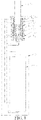
FIG. 1 is a cross-sectional view of an aerosol generating device according to some embodiments of the present invention; -
FIG. 2 is a cross-sectional view of an electromagnetic heating assembly shown inFIG. 1 ; -
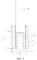
FIG. 3 is a schematic partial structural diagram of the electromagnetic heating assembly shown inFIG. 1 ; -
FIG. 4 is a schematic diagram of a proportional relationship of the electromagnetic heating assembly shown inFIG. 1 ; -
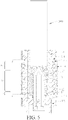
FIG. 5 is a schematic diagram of distribution of sensing regions of the electromagnetic heating assembly shown inFIG. 1 ; and -
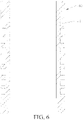
FIG. 6 is a cross-sectional view of a coil fixing cylinder of the electromagnetic heating assembly shown inFIG. 1 . - In order to have a clearer understanding of the technical features, the obj ectives, and the effects of the present invention, specific implementations of the present invention are now illustrated in detail with reference to the accompanying drawings.
- It should be understood that, the terms such as "front", "rear", "left", "right", "upper", "lower", "first", and "second" are used only for ease of describing the technical solutions of the present invention, rather than indicating or implying that the mentioned apparatus or component must have a particular difference. Therefore, such terms should not be construed as a limitation to the present invention. It should be noted that, when a component is considered to be "connected to" another component, the component may be directly connected to the another component, or an intervening component may be present. Unless otherwise defined, meanings of all technical and scientific terms used in this specification are the same as that usually understood by a person skilled in the technical field to which the present invention belongs. In this specification, terms used in this specification of the present invention are merely intended to describe objectives of the specific embodiments, but are not intended to limit the present invention.
-
FIG. 1 andFIG. 2 show some preferred embodiments of an aerosol generating device of the present invention. The aerosol generating device is a heat-not-burn cigarette device, which may heat components in an aerosol-formingsubstrate 100 through electromagnetic induction. In some embodiments, the aerosol-formingsubstrate 100 may be a cigarette. The aerosol generating device includes anelectromagnetic heating assembly 1, ashell 2, and apower supply component 3. Theelectromagnetic heating assembly 1 is arranged in theshell 2 and is mechanically and electrically connected to thepower supply component 3. Thepower supply component 3 is installed in theshell 2 and configured to energize theelectromagnetic heating assembly 1, to supply power to theelectromagnetic heating assembly 1. - Further, as shown in
FIG. 2 andFIG. 3 , the electromagnetic heating assembly includes afixing tube 10, abase 20, aheating body 30, acoil fixing cylinder 40, and aninduction coil 50. Two ends of thefixing tube 10 are provided in a run-through manner. The fixing tube is configured to fix an aerosol-formingsubstrate 100, and the fixing tube includes a first end and a second end. It should be noted that, the first end is an end for the heating body to penetrate, and the second end is an end for the aerosol-formingsubstrate 100 to penetrate and pass through. Thebase 20 is arranged on the second end of thefixing tube 10 and is configured to mount theheating body 30. Theheating body 30 at least partially extends from the first end of the fixingtube 10 into the fixingtube 10 and is inserted into the aerosol-formingsubstrate 100 in the fixingtube 10 in the axial direction of the fixingtube 10, to heat and vaporize components in the aerosol-forming substrate 200. Thecoil fixing cylinder 40 is sleeved outside the fixingtube 10, which is a hollow structure with two run-through ends and is configured to fix theinduction coil 50. Theinduction coil 30 is sleeved on the periphery of the fixingtube 10 and is located at the middle position of the fixingtube 10. Specifically, theinduction coil 50 is wound outside thecoil fixing cylinder 40 and generates electromagnetic induction under an energized state to cause theheating body 30 to generate heat. - Further, in some embodiments, the fixing
tube 10 is a hollow structure and includes atube body 11. Thetube body 11 is in the shape of a column with two run-through ends and is arranged in theshell 2 in a longitudinal direction. The inner diameter of the tube body matches the outer diameter of the aerosol-formingsubstrate 100, and the tube body is configured to fix the aerosol-formingsubstrate 100. In some embodiments, thetube body 11 includes a first end and a second end. The first end is provided for theheating body 30 to penetrate; and the second is provided for the aerosol-formingsubstrate 100 to pass through. It should be noted that, the first end of the fixingtube 10 is the first end of thetube body 11; and the second end of the fixingtube 10 is the second end of thetube body 11. In some embodiments, abottom wall 111 may be provided on the inner side of thetube body 11 close to the first end thereof. A via hole for theheating body 30 to pass through may be provided on thebottom wall 111, and an air inlet hole for an airflow to enter may also be provided on thebottom wall 111. In some embodiments, asecond air inlet 112 is provided on the peripheral wall of thetube body 11 close to the first end thereof, and thefirst air inlet 113 is in communication with the air inlet hole and is configured to transport air to the air inlet hole. An engagement portion 12 is arranged on the second end of thetube body 11. The engagement portion 12 is arranged on the peripheral wall of thetube body 11 and is arranged protruding out of the peripheral wall of thetube body 11, which is configured to engage with thecoil fixing cylinder 40. A gap between the engagement portion and thecoil fixing cylinder 40 form afirst air inlet 113. Thefirst air inlet 113 and thesecond air inlet 112 are in communication through thecoil fixing cylinder 40. It may be understood that, in some embodiments, the engagement portion 12 may be omitted. - Further, in some embodiments, the
base 20 is in the shape of a column and is detachably connected to the fixingtube 10. Thebase 20 includes a top wall and a side wall. An insertion hole is provided on the top wall of thebase 20, and the insertion hole is for insertion to theheating body 30. - Further, in some embodiments, the
heating body 30 is in the shape of an elongated sheet. It may be understood that, in some other embodiments, the shape of the heating body is not limited to an elongated sheet, but may be a column or a needle. A spire structure is provided on an end of the heating body away from thebase 20, and the spire structure is in the shape of a triangle, a wedge, or a cone. The heating body includes abase body 31 and a temperature measuringresistance circuit 32 arranged on thebase body 31. Thebase body 31 is in the shape of a sheet and is made of a magnetically conductive and electrically conductive material. The magnetically conductive and electrically conductive material may be one or more of iron, iron alloy, nickel, nickel alloy, graphite, or iron oxide. The base body is electrically conductive and includes a magnetic induction effect, so that the base body can generate eddy currents to generate heat, after theinduction coil 50 releases electromagnetic energy under an energized state, to heat the components in the aerosol-formingsubstrate 100. The temperature measuringresistance circuit 32 is laid on a surface of thebase body 31 and may be integrally formed with thebase body 31. Specifically, an insulting layer may be printed on the surface of thebase body 31, and the temperature measuringresistance circuit 32 may be arranged on the insulating layer. Currents may be conducted to two ends of the temperature measuring resistance circuit, and a temperature of thebase body 31 may be obtained in real time according to a resistance change. It may be understood that, in some other embodiments, the temperature measuringresistance circuit 32 may be omitted. - As shown in
FIG. 3 to FIG. 6 , in some embodiments, thecoil fixing cylinder 40 is in the shape of a column, where the inner diameter of the coil fixing cylinder may be slightly greater than the outer diameter of the fixingtube 10, and an air inlet channel may be provided on the inner side of the coil fixing cylinder. The air inlet channel is in communication with the first air inlet and thesecond air inlet 112, to help air enter the fixingtube 10. A plurality of positioning grooves are provided on the outer side wall of thecoil fixing cylinder 40, and the plurality of positioning grooves are spaced in the axial direction of thecoil fixing cylinder 40 and are provided in a manner of extending along the circumferential direction of thecoil fixing cylinder 40. The positioning groove is provided for winding theinduction coil 50 and can prevent theinduction coil 50 from falling out of thecoil fixing cylinder 40, thereby resolving a problem that aninduction coil 50 formed by high-frequency Litz wires (a plurality of extremely small enameled wires) is too flexible to be positioned. In some embodiments, the positioning groove can further define the inter-turn spacing of theinduction coil 50, to accurately control the inter-turn spacing of theinduction coil 50. In addition, an area of theinduction coil 50 attached to a cylinder wall can be maximized, and an effect of reducing magnetic leakage and improving the energy conversion efficiency can be further achieved. - As shown in
FIG. 4 , further, in some embodiments, theinduction coil 50 is made of high-frequency Litz wires (a plurality of extremely small enameled wires) and is in the shape of a spiral, which is wound on thepositioning grooves 41 of thecoil fixing cylinder 40. In some embodiments, the ratio of the total height h of theinduction coil 50 to the depth h1 by which theheating body 30 is inserted into the aerosol-formingsubstrate 100 in the fixingtube 10 is between 1:1 and 3:1. That is, h/h1 is between 1:1 and 3:1. In a case that an input power of theinduction coil 50 is unchanged, the distribution of the high temperature region on theheating body 30 can be learned according to the relationship equation. A smaller ratio indicates a small high temperature region on theheating body 30, and a higher and concentrated temperature of the high temperature region in this case; and a larger ratio indicates a larger high temperature region and more scattered temperature. A user may adjust the distribution of the high temperature region on the heating body correspondingly according to the relationship equation, to further prevent the heating body from being non-available due to an excessively high temperature, thereby improving the user experience. In some embodiments, optionally, the ratio of the total height h of theinduction coil 50 to the depth h1 by which theheating body 30 is inserted into the aerosol-formingsubstrate 100 in the fixingtube 10 is between 1.2:1 and 1.5:1. That is, h/h1 is between 1.2:1 and 1.5:1. In some embodiments, a value of the depth h1 by which theheating body 30 is inserted into the aerosol-formingsubstrate 100 in the fixingtube 10 may range from 9 mm to 15 mm. - Further, in some embodiments, the ratio of the inner diameter d of the
induction coil 50 to the width d1 of theheating body 30 may range from 1.2:1 to 3:1. That is, d/d1 is between 1.2:1 and 3:1, and the relationship equation decides changes of the heating efficiency. A smaller ratio of the inner diameter d of theinduction coil 50 to the width d1 of theheating body 30 indicates a higher heating efficiency. In some embodiments, a value of d1 is between 3 mm and 5.5 mm. - As shown in
FIG. 5 , further, in some embodiments, theinduction coil 50 may include a first sensing region A, a second sensing region B, and a third sensing region C. The first sensing region A, the second sensing region B, and the third sensing region C are provided sequentially toward the first end of the fixingtube 10. The average inter-turn spacing of the first sensing region A is greater than the average inter-turn spacing of the third sensing region C, and the average inter-turn spacing of the third sensing region C is greater than the average inter-turn spacing of the second sensing region B, so that the numbers of magnetic lines passing through the regions of theheating body 30 are the same, and temperature field distribution is more uniform. Correspondingly, the number ofpositioning grooves 41 per unit height in a region provided corresponding to the first sensing region A on thecoil fixing cylinder 40 is greater than the number ofpositioning grooves 41 per unit height in a region provided corresponding to the third sensing region C on thecoil fixing cylinder 40; and Correspondingly, the number ofpositioning grooves 41 per unit height in the region provided corresponding to the third sensing region C on thecoil fixing cylinder 40 is greater than the number ofpositioning grooves 41 per unit height in a region provided corresponding to the second sensing region B on thecoil fixing cylinder 40. - Still referring to
FIG. 4 , in some embodiments, the electromagnetic heating assembly further includes aprotective film 60. Theprotective film 60 is arranged on the periphery of theinduction coil 50. Specifically, the protective film is wrapped on the periphery of theinduction coil 50, and is configured to increase an inductance, improve a heating speed, and prevent magnetic leakage from affecting operation of electronic components and causing damage to a human body. Theprotective film 60 may be in the shape of a column, and the height thereof is greater than the total height of theinduction coil 50. Specifically, the height of the protective film matches the height of thecoil fixing cylinder 40. In some embodiments, the height H of theprotective film 60 is equal to h+2h3, where a value of h3 is between 0.5 mm and 6 mm. In some embodiments, theprotective film 60 is a ferrite film and the material thereof is manganese-zinc ferrite. Certainly, it may be understood that, in some other embodiments, theprotective film 60 is not limited to the manganese-zinc ferrite material, and may be formed by ferric oxide with one or more of other metal oxides (for example, nickel oxide, zinc oxide, manganese oxide, magnesium oxide, barium oxide, and strontium oxide) through preparation and sintering. In some embodiments, the magnetic permeability of theprotective film 60 is between 500 and 2000, and the thickness thereof is between 0.1 mm and 0.5 mm. - While the invention has been illustrated and described in detail in the drawings and foregoing description, such illustration and description are to be considered illustrative or exemplary and not restrictive. It will be understood that changes and modifications may be made by those of ordinary skill within the scope of the following claims. In particular, the present invention covers further embodiments with any combination of features from different embodiments described above and below. Additionally, statements made herein characterizing the invention refer to an embodiment of the invention and not necessarily all embodiments.
Claims (15)
- An electromagnetic heating assembly, comprising:a fixing tube (10) with two run-through ends configured to fix aerosol-forming substrate (100);a heating body (30) at least partially extending from a first end of the fixing tube (10) into the fixing tube (10) and inserted into aerosol-forming substrate (100) in the fixing tube (10); andan induction coil (50) sleeved on the periphery of the fixing tube (10) and configured to generate electromagnetic induction under an energized state so as to cause the heating body (30) to heat;wherein the ratio of the total height of the induction coil (50) to the depth by which the heating body (30) is inserted into aerosol-forming substrate (100) in the fixing tube (10) is between 1:1 and 3:1.
- The electromagnetic heating assembly of claim 1, wherein the ratio of the total height of the induction coil (50) to the depth by which the heating body (30) is inserted into aerosol-forming substrate (100) in the fixing tube (10) is between 1.2:1 and 1.5:1.
- The electromagnetic heating assembly of claim 1, wherein the heating body (30) is in the shape of a sheet;wherein the induction coil (50) is in the shape of a spiral; andwherein the ratio of the inner diameter of the induction coil (50) to the width of the heating body (30) is between 1.2:1 and 3:1.
- The electromagnetic heating assembly of claim 1, wherein the induction coil (50) comprises a first sensing region, a second sensing region, and a third sensing region that are arranged sequentially toward the first end of the fixing tube (10);the average inter-turn spacing of the first sensing region is greater than the average inter-turn spacing of the third sensing region; andthe average inter-turn spacing of the third sensing region is greater than the average inter-turn spacing of the second sensing region.
- The electromagnetic heating assembly of claim 1, further comprising:a coil fixing cylinder (40) sleeved outside the fixing tube (10) to fix the induction coil (50),wherein the induction coil (50) is wound on the coil fixing cylinder (40).
- The electromagnetic heating assembly of claim 5, wherein a plurality of positioning grooves configured to wind the induction coil (50) to define the inter-turn spacing of the induction coil (50) are provided on the outer side wall of the coil fixing cylinder (40).
- The electromagnetic heating assembly of claim 5, further comprising:
a protective film (60) arranged on the periphery of the induction coil (50) and configured to increase an inductance and prevent magnetic leakage. - The electromagnetic heating assembly of claim 7, wherein the height of the protective film (60) is greater than the total height of the induction coil (50).
- The electromagnetic heating assembly of claim 8, wherein the height of the protective film (60) adapts to the height of the coil fixing cylinder (40).
- The electromagnetic heating assembly of claim 7, wherein the magnetic permeability of the protective film (60) is between 500 and 2000.
- The electromagnetic heating assembly of claim 7, wherein the thickness of the protective film (60) is between 0.1 mm and 0.5 mm.
- The electromagnetic heating assembly of claim 7, wherein the protective film (60) is a ferrite film.
- The electromagnetic heating assembly of claim 1, further comprising:
a base (20) arranged on the first end of the fixing tube (10) and configured to mount the heating body (30). - The electromagnetic heating assembly of claim 5, wherein the fixing tube (10) comprises a tube body (11) with two run-through ends to fix aerosol-forming substrate (100);wherein the tube body (11) comprises a first end for the heating body (30) to penetrate and a second end for aerosol-forming substrate (100) to pass through;wherein an engagement portion (12) arranged protruding out of the peripheral wall of the tube body (11) to engage with the coil fixing cylinder (40) is arranged on the second end of the tube body (11);wherein a gap between the coil fixing cylinder (40) and the engagement portion (12) forms a first air inlet (113);wherein a second air inlet (112) is provided on the peripheral wall of the tube body (11) close to the first end; andwherein an air inlet channel in communication with the first air inlet (113) and the second air inlet (112) is provided on the inner side of the coil fixing cylinder (40).
- An aerosol generating device, comprising:a shell (2);the electromagnetic heating assembly (1) of any one of claims 1 to 14 and arranged in the shell (2); anda power supply component (3) arranged in the shell (2) and configured to energize the electromagnetic heating assembly (1).
Applications Claiming Priority (2)
| Application Number | Priority Date | Filing Date | Title |
|---|---|---|---|
| CN202020412900.8U CN212233104U (en) | 2020-03-26 | 2020-03-26 | Aerosol generating device and electromagnetic heating component thereof |
| PCT/CN2021/077111 WO2021190214A1 (en) | 2020-03-26 | 2021-02-20 | Aerosol generating device and electromagnetic heating assembly thereof |
Publications (2)
| Publication Number | Publication Date |
|---|---|
| EP4111884A1 true EP4111884A1 (en) | 2023-01-04 |
| EP4111884A4 EP4111884A4 (en) | 2023-09-27 |
Family
ID=73986694
Family Applications (1)
| Application Number | Title | Priority Date | Filing Date |
|---|---|---|---|
| EP21776842.3A Pending EP4111884A4 (en) | 2020-03-26 | 2021-02-20 | AEROSOL GENERATION DEVICE AND ASSOCIATED ELECTROMAGNETIC HEATING ASSEMBLY |
Country Status (4)
| Country | Link |
|---|---|
| US (1) | US12439970B2 (en) |
| EP (1) | EP4111884A4 (en) |
| CN (1) | CN212233104U (en) |
| WO (1) | WO2021190214A1 (en) |
Families Citing this family (12)
| Publication number | Priority date | Publication date | Assignee | Title |
|---|---|---|---|---|
| CN212233104U (en) * | 2020-03-26 | 2020-12-29 | 深圳麦克韦尔科技有限公司 | Aerosol generating device and electromagnetic heating component thereof |
| GB202014597D0 (en) * | 2020-09-16 | 2020-10-28 | Nicoventures Trading Ltd | Aerosol provision device |
| KR102542026B1 (en) * | 2021-06-23 | 2023-06-12 | 주식회사 케이티앤지 | Device for generating aerosol |
| CN113349455B (en) * | 2021-07-14 | 2025-06-13 | 上海烟草集团有限责任公司 | Aerosol generating device and aerosol generating system |
| CN113647698B (en) * | 2021-08-23 | 2025-09-05 | 深圳麦克韦尔科技有限公司 | Atomization medium carrier and atomization system |
| CN116135061A (en) * | 2021-11-16 | 2023-05-19 | 深圳市合元科技有限公司 | Aerosol generating device and induction coil |
| CN216875045U (en) * | 2021-12-18 | 2022-07-05 | 深圳麦克韦尔科技有限公司 | Atomization assembly and electronic atomizer |
| CN114931239A (en) * | 2022-05-23 | 2022-08-23 | 深圳麦克韦尔科技有限公司 | Coil winding provided with air interlayer and aerosol generating device |
| CN114983024A (en) * | 2022-06-02 | 2022-09-02 | 深圳麦克韦尔科技有限公司 | Electromagnetic heating coils, heating components and electronic atomizing devices |
| CN115088877A (en) * | 2022-06-15 | 2022-09-23 | 深圳麦时科技有限公司 | Aerosol-generating device and aerosol-forming substrate assembly |
| CN116268622A (en) * | 2023-03-10 | 2023-06-23 | 深圳市吉迩科技有限公司 | An aerosol generating product, a heating component and an aerosol generating device thereof |
| CN118923958A (en) * | 2023-05-09 | 2024-11-12 | 思摩尔国际控股有限公司 | Aerosol generating device and heating structure |
Family Cites Families (14)
| Publication number | Priority date | Publication date | Assignee | Title |
|---|---|---|---|---|
| UA114651C2 (en) | 2012-12-28 | 2017-07-10 | Філіп Морріс Продактс С.А. | Heating assembly for an aerosol generating system |
| PL3337344T3 (en) * | 2015-08-17 | 2019-12-31 | Philip Morris Products S.A. | Aerosol-generating system and aerosol-generating article for use in such a system |
| US20170055580A1 (en) * | 2015-08-31 | 2017-03-02 | British American Tobacco (Investments) Limited | Apparatus for heating smokable material |
| RU2731029C1 (en) * | 2017-08-09 | 2020-08-28 | Филип Моррис Продактс С.А. | Aerosol-generating device with modular induction heater |
| US10517332B2 (en) * | 2017-10-31 | 2019-12-31 | Rai Strategic Holdings, Inc. | Induction heated aerosol delivery device |
| CN207754555U (en) * | 2017-12-22 | 2018-08-24 | 深圳市合元科技有限公司 | A kind of heating device and smoking set |
| JP6766128B2 (en) * | 2017-12-22 | 2020-10-07 | 深▲せん▼市合元科技有限公司Shenzhen First Union Technology Co.,Ltd | Heating device and smoking equipment |
| CN207754554U (en) * | 2017-12-22 | 2018-08-24 | 深圳市合元科技有限公司 | A kind of heating device and smoking set |
| CN207766584U (en) * | 2018-01-31 | 2018-08-24 | 深圳市合元科技有限公司 | A kind of heating device and electronic cigarette |
| CN108323824A (en) | 2018-04-27 | 2018-07-27 | 常州市派腾电子技术服务有限公司 | Control method, device and the electronic cigarette of electronic cigarette |
| CN108617042A (en) * | 2018-07-05 | 2018-10-02 | 湖北中烟工业有限责任公司 | A kind of smoking apparatus of induced inside heating |
| CN110169594A (en) * | 2018-12-25 | 2019-08-27 | 惠州市沛格斯科技有限公司 | Heating module, controllable heating module and electronic smoking set |
| CN110122928A (en) | 2019-04-30 | 2019-08-16 | 安徽中烟工业有限责任公司 | It is a kind of for heating the heating device for the smoking set that do not burn |
| CN212233104U (en) * | 2020-03-26 | 2020-12-29 | 深圳麦克韦尔科技有限公司 | Aerosol generating device and electromagnetic heating component thereof |
-
2020
- 2020-03-26 CN CN202020412900.8U patent/CN212233104U/en active Active
-
2021
- 2021-02-20 WO PCT/CN2021/077111 patent/WO2021190214A1/en not_active Ceased
- 2021-02-20 EP EP21776842.3A patent/EP4111884A4/en active Pending
-
2022
- 2022-09-23 US US17/934,936 patent/US12439970B2/en active Active
Also Published As
| Publication number | Publication date |
|---|---|
| EP4111884A4 (en) | 2023-09-27 |
| WO2021190214A1 (en) | 2021-09-30 |
| CN212233104U (en) | 2020-12-29 |
| US12439970B2 (en) | 2025-10-14 |
| US20230015720A1 (en) | 2023-01-19 |
Similar Documents
| Publication | Publication Date | Title |
|---|---|---|
| US12439970B2 (en) | Aerosol generating device and electromagnetic heating assembly thereof | |
| CN113453571B (en) | Heater for cigarette type electronic cigarette device and cigarette type electronic cigarette device including the same | |
| TWI666993B (en) | Inductive heating device and system for aerosol generation | |
| US20250098759A1 (en) | Container for electronic vaporizer device | |
| CN105191050B (en) | Induction charging for electronic cigarette | |
| EP3476231A1 (en) | Aerosol generating device capable of adjusting heating area | |
| US12171267B2 (en) | Heater for cigarette-type electronic cigarette device, and cigarette-type electronic cigarette device including the same | |
| JP7656607B2 (en) | Aerosol Generation System | |
| JP2022530610A (en) | A smoke generator that induces heating with the tip of a cigarette | |
| JP2021522643A5 (en) | ||
| EP4066666A1 (en) | Electronic atomization device, heating element thereof, and heating structure | |
| WO2023207296A1 (en) | Aerosol generation device and heating assembly | |
| JP7451550B2 (en) | Aerosol delivery device | |
| WO2024217392A1 (en) | Electromagnetic induction coil, electromagnetic induction apparatus, and cigarette-heating smoking tool | |
| US20240057227A1 (en) | Induction Heating Assembly | |
| CN219781603U (en) | An aerosol generating product, a heating component and an aerosol generating device thereof | |
| CN220274905U (en) | Heating components and aerosol generating devices | |
| CN217826738U (en) | Heater and aerosol generating device | |
| CN114504133A (en) | Electronic cigarette atomization heating assembly, electronic cigarette and control method | |
| CN217771509U (en) | e-cigarette | |
| CN215736934U (en) | Cage type external magnetic shielding electromagnetic induction heating smoking set | |
| KR20230130784A (en) | Heating device of aerosol generator having intake air heating structure | |
| CN222217217U (en) | Heating assembly and aerosol generating device | |
| CN220274944U (en) | Heat exchange core, heating device and electronic atomization device | |
| CN113397225A (en) | Cage type external magnetic shielding electromagnetic induction heating smoking set |
Legal Events
| Date | Code | Title | Description |
|---|---|---|---|
| STAA | Information on the status of an ep patent application or granted ep patent |
Free format text: STATUS: THE INTERNATIONAL PUBLICATION HAS BEEN MADE |
|
| PUAI | Public reference made under article 153(3) epc to a published international application that has entered the european phase |
Free format text: ORIGINAL CODE: 0009012 |
|
| STAA | Information on the status of an ep patent application or granted ep patent |
Free format text: STATUS: REQUEST FOR EXAMINATION WAS MADE |
|
| 17P | Request for examination filed |
Effective date: 20220926 |
|
| AK | Designated contracting states |
Kind code of ref document: A1 Designated state(s): AL AT BE BG CH CY CZ DE DK EE ES FI FR GB GR HR HU IE IS IT LI LT LU LV MC MK MT NL NO PL PT RO RS SE SI SK SM TR |
|
| DAV | Request for validation of the european patent (deleted) | ||
| DAX | Request for extension of the european patent (deleted) | ||
| REG | Reference to a national code |
Ref country code: DE Ref legal event code: R079 Free format text: PREVIOUS MAIN CLASS: A24F0040400000 Ipc: A24F0040465000 |
|
| A4 | Supplementary search report drawn up and despatched |
Effective date: 20230824 |
|
| RIC1 | Information provided on ipc code assigned before grant |
Ipc: H05B 6/10 20060101ALI20230818BHEP Ipc: A24F 40/20 20200101ALI20230818BHEP Ipc: A24F 40/465 20200101AFI20230818BHEP |
|
| RAP3 | Party data changed (applicant data changed or rights of an application transferred) |
Owner name: SHENZHEN SMOORE TECHNOLOGY LIMITED |
|
| RAP3 | Party data changed (applicant data changed or rights of an application transferred) |
Owner name: SHENZHEN SMOORE TECHNOLOGY LIMITED |
|
| STAA | Information on the status of an ep patent application or granted ep patent |
Free format text: STATUS: EXAMINATION IS IN PROGRESS |
|
| 17Q | First examination report despatched |
Effective date: 20251113 |