EP4110236B1 - Coupling system of the components of a shoulder joint prosthesis - Google Patents
Coupling system of the components of a shoulder joint prosthesis Download PDFInfo
- Publication number
- EP4110236B1 EP4110236B1 EP21704610.1A EP21704610A EP4110236B1 EP 4110236 B1 EP4110236 B1 EP 4110236B1 EP 21704610 A EP21704610 A EP 21704610A EP 4110236 B1 EP4110236 B1 EP 4110236B1
- Authority
- EP
- European Patent Office
- Prior art keywords
- hole
- pin element
- section
- coupling system
- metal support
- Prior art date
- Legal status (The legal status is an assumption and is not a legal conclusion. Google has not performed a legal analysis and makes no representation as to the accuracy of the status listed.)
- Active
Links
Images




Classifications
-
- A—HUMAN NECESSITIES
- A61—MEDICAL OR VETERINARY SCIENCE; HYGIENE
- A61F—FILTERS IMPLANTABLE INTO BLOOD VESSELS; PROSTHESES; DEVICES PROVIDING PATENCY TO, OR PREVENTING COLLAPSING OF, TUBULAR STRUCTURES OF THE BODY, e.g. STENTS; ORTHOPAEDIC, NURSING OR CONTRACEPTIVE DEVICES; FOMENTATION; TREATMENT OR PROTECTION OF EYES OR EARS; BANDAGES, DRESSINGS OR ABSORBENT PADS; FIRST-AID KITS
- A61F2/00—Filters implantable into blood vessels; Prostheses, i.e. artificial substitutes or replacements for parts of the body; Appliances for connecting them with the body; Devices providing patency to, or preventing collapsing of, tubular structures of the body, e.g. stents
- A61F2/02—Prostheses implantable into the body
- A61F2/30—Joints
- A61F2/40—Joints for shoulders
- A61F2/4081—Glenoid components, e.g. cups
-
- A—HUMAN NECESSITIES
- A61—MEDICAL OR VETERINARY SCIENCE; HYGIENE
- A61F—FILTERS IMPLANTABLE INTO BLOOD VESSELS; PROSTHESES; DEVICES PROVIDING PATENCY TO, OR PREVENTING COLLAPSING OF, TUBULAR STRUCTURES OF THE BODY, e.g. STENTS; ORTHOPAEDIC, NURSING OR CONTRACEPTIVE DEVICES; FOMENTATION; TREATMENT OR PROTECTION OF EYES OR EARS; BANDAGES, DRESSINGS OR ABSORBENT PADS; FIRST-AID KITS
- A61F2/00—Filters implantable into blood vessels; Prostheses, i.e. artificial substitutes or replacements for parts of the body; Appliances for connecting them with the body; Devices providing patency to, or preventing collapsing of, tubular structures of the body, e.g. stents
- A61F2/02—Prostheses implantable into the body
- A61F2/30—Joints
- A61F2002/30001—Additional features of subject-matter classified in A61F2/28, A61F2/30 and subgroups thereof
- A61F2002/30316—The prosthesis having different structural features at different locations within the same prosthesis; Connections between prosthetic parts; Special structural features of bone or joint prostheses not otherwise provided for
- A61F2002/30329—Connections or couplings between prosthetic parts, e.g. between modular parts; Connecting elements
- A61F2002/30331—Connections or couplings between prosthetic parts, e.g. between modular parts; Connecting elements made by longitudinally pushing a protrusion into a complementarily-shaped recess, e.g. held by friction fit
-
- A—HUMAN NECESSITIES
- A61—MEDICAL OR VETERINARY SCIENCE; HYGIENE
- A61F—FILTERS IMPLANTABLE INTO BLOOD VESSELS; PROSTHESES; DEVICES PROVIDING PATENCY TO, OR PREVENTING COLLAPSING OF, TUBULAR STRUCTURES OF THE BODY, e.g. STENTS; ORTHOPAEDIC, NURSING OR CONTRACEPTIVE DEVICES; FOMENTATION; TREATMENT OR PROTECTION OF EYES OR EARS; BANDAGES, DRESSINGS OR ABSORBENT PADS; FIRST-AID KITS
- A61F2/00—Filters implantable into blood vessels; Prostheses, i.e. artificial substitutes or replacements for parts of the body; Appliances for connecting them with the body; Devices providing patency to, or preventing collapsing of, tubular structures of the body, e.g. stents
- A61F2/02—Prostheses implantable into the body
- A61F2/30—Joints
- A61F2002/30001—Additional features of subject-matter classified in A61F2/28, A61F2/30 and subgroups thereof
- A61F2002/30316—The prosthesis having different structural features at different locations within the same prosthesis; Connections between prosthetic parts; Special structural features of bone or joint prostheses not otherwise provided for
- A61F2002/30329—Connections or couplings between prosthetic parts, e.g. between modular parts; Connecting elements
- A61F2002/30331—Connections or couplings between prosthetic parts, e.g. between modular parts; Connecting elements made by longitudinally pushing a protrusion into a complementarily-shaped recess, e.g. held by friction fit
- A61F2002/30332—Conically- or frustoconically-shaped protrusion and recess
-
- A—HUMAN NECESSITIES
- A61—MEDICAL OR VETERINARY SCIENCE; HYGIENE
- A61F—FILTERS IMPLANTABLE INTO BLOOD VESSELS; PROSTHESES; DEVICES PROVIDING PATENCY TO, OR PREVENTING COLLAPSING OF, TUBULAR STRUCTURES OF THE BODY, e.g. STENTS; ORTHOPAEDIC, NURSING OR CONTRACEPTIVE DEVICES; FOMENTATION; TREATMENT OR PROTECTION OF EYES OR EARS; BANDAGES, DRESSINGS OR ABSORBENT PADS; FIRST-AID KITS
- A61F2/00—Filters implantable into blood vessels; Prostheses, i.e. artificial substitutes or replacements for parts of the body; Appliances for connecting them with the body; Devices providing patency to, or preventing collapsing of, tubular structures of the body, e.g. stents
- A61F2/02—Prostheses implantable into the body
- A61F2/30—Joints
- A61F2002/30001—Additional features of subject-matter classified in A61F2/28, A61F2/30 and subgroups thereof
- A61F2002/30316—The prosthesis having different structural features at different locations within the same prosthesis; Connections between prosthetic parts; Special structural features of bone or joint prostheses not otherwise provided for
- A61F2002/30329—Connections or couplings between prosthetic parts, e.g. between modular parts; Connecting elements
- A61F2002/30331—Connections or couplings between prosthetic parts, e.g. between modular parts; Connecting elements made by longitudinally pushing a protrusion into a complementarily-shaped recess, e.g. held by friction fit
- A61F2002/30332—Conically- or frustoconically-shaped protrusion and recess
- A61F2002/30339—Double cones, i.e. connecting element having two conical connections, one at each of its opposite ends
-
- A—HUMAN NECESSITIES
- A61—MEDICAL OR VETERINARY SCIENCE; HYGIENE
- A61F—FILTERS IMPLANTABLE INTO BLOOD VESSELS; PROSTHESES; DEVICES PROVIDING PATENCY TO, OR PREVENTING COLLAPSING OF, TUBULAR STRUCTURES OF THE BODY, e.g. STENTS; ORTHOPAEDIC, NURSING OR CONTRACEPTIVE DEVICES; FOMENTATION; TREATMENT OR PROTECTION OF EYES OR EARS; BANDAGES, DRESSINGS OR ABSORBENT PADS; FIRST-AID KITS
- A61F2/00—Filters implantable into blood vessels; Prostheses, i.e. artificial substitutes or replacements for parts of the body; Appliances for connecting them with the body; Devices providing patency to, or preventing collapsing of, tubular structures of the body, e.g. stents
- A61F2/02—Prostheses implantable into the body
- A61F2/30—Joints
- A61F2002/30001—Additional features of subject-matter classified in A61F2/28, A61F2/30 and subgroups thereof
- A61F2002/30316—The prosthesis having different structural features at different locations within the same prosthesis; Connections between prosthetic parts; Special structural features of bone or joint prostheses not otherwise provided for
- A61F2002/30329—Connections or couplings between prosthetic parts, e.g. between modular parts; Connecting elements
- A61F2002/30405—Connections or couplings between prosthetic parts, e.g. between modular parts; Connecting elements made by screwing complementary threads machined on the parts themselves
-
- A—HUMAN NECESSITIES
- A61—MEDICAL OR VETERINARY SCIENCE; HYGIENE
- A61F—FILTERS IMPLANTABLE INTO BLOOD VESSELS; PROSTHESES; DEVICES PROVIDING PATENCY TO, OR PREVENTING COLLAPSING OF, TUBULAR STRUCTURES OF THE BODY, e.g. STENTS; ORTHOPAEDIC, NURSING OR CONTRACEPTIVE DEVICES; FOMENTATION; TREATMENT OR PROTECTION OF EYES OR EARS; BANDAGES, DRESSINGS OR ABSORBENT PADS; FIRST-AID KITS
- A61F2/00—Filters implantable into blood vessels; Prostheses, i.e. artificial substitutes or replacements for parts of the body; Appliances for connecting them with the body; Devices providing patency to, or preventing collapsing of, tubular structures of the body, e.g. stents
- A61F2/02—Prostheses implantable into the body
- A61F2/30—Joints
- A61F2002/30001—Additional features of subject-matter classified in A61F2/28, A61F2/30 and subgroups thereof
- A61F2002/30316—The prosthesis having different structural features at different locations within the same prosthesis; Connections between prosthetic parts; Special structural features of bone or joint prostheses not otherwise provided for
- A61F2002/30329—Connections or couplings between prosthetic parts, e.g. between modular parts; Connecting elements
- A61F2002/30433—Connections or couplings between prosthetic parts, e.g. between modular parts; Connecting elements using additional screws, bolts, dowels, rivets or washers e.g. connecting screws
-
- A—HUMAN NECESSITIES
- A61—MEDICAL OR VETERINARY SCIENCE; HYGIENE
- A61F—FILTERS IMPLANTABLE INTO BLOOD VESSELS; PROSTHESES; DEVICES PROVIDING PATENCY TO, OR PREVENTING COLLAPSING OF, TUBULAR STRUCTURES OF THE BODY, e.g. STENTS; ORTHOPAEDIC, NURSING OR CONTRACEPTIVE DEVICES; FOMENTATION; TREATMENT OR PROTECTION OF EYES OR EARS; BANDAGES, DRESSINGS OR ABSORBENT PADS; FIRST-AID KITS
- A61F2/00—Filters implantable into blood vessels; Prostheses, i.e. artificial substitutes or replacements for parts of the body; Appliances for connecting them with the body; Devices providing patency to, or preventing collapsing of, tubular structures of the body, e.g. stents
- A61F2/02—Prostheses implantable into the body
- A61F2/30—Joints
- A61F2002/30001—Additional features of subject-matter classified in A61F2/28, A61F2/30 and subgroups thereof
- A61F2002/30316—The prosthesis having different structural features at different locations within the same prosthesis; Connections between prosthetic parts; Special structural features of bone or joint prostheses not otherwise provided for
- A61F2002/30329—Connections or couplings between prosthetic parts, e.g. between modular parts; Connecting elements
- A61F2002/30476—Connections or couplings between prosthetic parts, e.g. between modular parts; Connecting elements locked by an additional locking mechanism
- A61F2002/30507—Connections or couplings between prosthetic parts, e.g. between modular parts; Connecting elements locked by an additional locking mechanism using a threaded locking member, e.g. a locking screw or a set screw
-
- A—HUMAN NECESSITIES
- A61—MEDICAL OR VETERINARY SCIENCE; HYGIENE
- A61F—FILTERS IMPLANTABLE INTO BLOOD VESSELS; PROSTHESES; DEVICES PROVIDING PATENCY TO, OR PREVENTING COLLAPSING OF, TUBULAR STRUCTURES OF THE BODY, e.g. STENTS; ORTHOPAEDIC, NURSING OR CONTRACEPTIVE DEVICES; FOMENTATION; TREATMENT OR PROTECTION OF EYES OR EARS; BANDAGES, DRESSINGS OR ABSORBENT PADS; FIRST-AID KITS
- A61F2/00—Filters implantable into blood vessels; Prostheses, i.e. artificial substitutes or replacements for parts of the body; Appliances for connecting them with the body; Devices providing patency to, or preventing collapsing of, tubular structures of the body, e.g. stents
- A61F2/02—Prostheses implantable into the body
- A61F2/30—Joints
- A61F2002/30001—Additional features of subject-matter classified in A61F2/28, A61F2/30 and subgroups thereof
- A61F2002/30316—The prosthesis having different structural features at different locations within the same prosthesis; Connections between prosthetic parts; Special structural features of bone or joint prostheses not otherwise provided for
- A61F2002/30535—Special structural features of bone or joint prostheses not otherwise provided for
- A61F2002/30604—Special structural features of bone or joint prostheses not otherwise provided for modular
-
- A—HUMAN NECESSITIES
- A61—MEDICAL OR VETERINARY SCIENCE; HYGIENE
- A61F—FILTERS IMPLANTABLE INTO BLOOD VESSELS; PROSTHESES; DEVICES PROVIDING PATENCY TO, OR PREVENTING COLLAPSING OF, TUBULAR STRUCTURES OF THE BODY, e.g. STENTS; ORTHOPAEDIC, NURSING OR CONTRACEPTIVE DEVICES; FOMENTATION; TREATMENT OR PROTECTION OF EYES OR EARS; BANDAGES, DRESSINGS OR ABSORBENT PADS; FIRST-AID KITS
- A61F2/00—Filters implantable into blood vessels; Prostheses, i.e. artificial substitutes or replacements for parts of the body; Appliances for connecting them with the body; Devices providing patency to, or preventing collapsing of, tubular structures of the body, e.g. stents
- A61F2/02—Prostheses implantable into the body
- A61F2/30—Joints
- A61F2/30767—Special external or bone-contacting surface, e.g. coating for improving bone ingrowth
- A61F2/30771—Special external or bone-contacting surface, e.g. coating for improving bone ingrowth applied in original prostheses, e.g. holes or grooves
- A61F2002/30772—Apertures or holes, e.g. of circular cross section
- A61F2002/30774—Apertures or holes, e.g. of circular cross section internally-threaded
-
- A—HUMAN NECESSITIES
- A61—MEDICAL OR VETERINARY SCIENCE; HYGIENE
- A61F—FILTERS IMPLANTABLE INTO BLOOD VESSELS; PROSTHESES; DEVICES PROVIDING PATENCY TO, OR PREVENTING COLLAPSING OF, TUBULAR STRUCTURES OF THE BODY, e.g. STENTS; ORTHOPAEDIC, NURSING OR CONTRACEPTIVE DEVICES; FOMENTATION; TREATMENT OR PROTECTION OF EYES OR EARS; BANDAGES, DRESSINGS OR ABSORBENT PADS; FIRST-AID KITS
- A61F2/00—Filters implantable into blood vessels; Prostheses, i.e. artificial substitutes or replacements for parts of the body; Appliances for connecting them with the body; Devices providing patency to, or preventing collapsing of, tubular structures of the body, e.g. stents
- A61F2/02—Prostheses implantable into the body
- A61F2/30—Joints
- A61F2/30767—Special external or bone-contacting surface, e.g. coating for improving bone ingrowth
- A61F2/30771—Special external or bone-contacting surface, e.g. coating for improving bone ingrowth applied in original prostheses, e.g. holes or grooves
- A61F2002/30772—Apertures or holes, e.g. of circular cross section
- A61F2002/30784—Plurality of holes
-
- A—HUMAN NECESSITIES
- A61—MEDICAL OR VETERINARY SCIENCE; HYGIENE
- A61F—FILTERS IMPLANTABLE INTO BLOOD VESSELS; PROSTHESES; DEVICES PROVIDING PATENCY TO, OR PREVENTING COLLAPSING OF, TUBULAR STRUCTURES OF THE BODY, e.g. STENTS; ORTHOPAEDIC, NURSING OR CONTRACEPTIVE DEVICES; FOMENTATION; TREATMENT OR PROTECTION OF EYES OR EARS; BANDAGES, DRESSINGS OR ABSORBENT PADS; FIRST-AID KITS
- A61F2/00—Filters implantable into blood vessels; Prostheses, i.e. artificial substitutes or replacements for parts of the body; Appliances for connecting them with the body; Devices providing patency to, or preventing collapsing of, tubular structures of the body, e.g. stents
- A61F2/02—Prostheses implantable into the body
- A61F2/30—Joints
- A61F2/30767—Special external or bone-contacting surface, e.g. coating for improving bone ingrowth
- A61F2/30771—Special external or bone-contacting surface, e.g. coating for improving bone ingrowth applied in original prostheses, e.g. holes or grooves
- A61F2002/30772—Apertures or holes, e.g. of circular cross section
- A61F2002/3079—Stepped or enlarged apertures, e.g. having discrete diameter changes
-
- A—HUMAN NECESSITIES
- A61—MEDICAL OR VETERINARY SCIENCE; HYGIENE
- A61F—FILTERS IMPLANTABLE INTO BLOOD VESSELS; PROSTHESES; DEVICES PROVIDING PATENCY TO, OR PREVENTING COLLAPSING OF, TUBULAR STRUCTURES OF THE BODY, e.g. STENTS; ORTHOPAEDIC, NURSING OR CONTRACEPTIVE DEVICES; FOMENTATION; TREATMENT OR PROTECTION OF EYES OR EARS; BANDAGES, DRESSINGS OR ABSORBENT PADS; FIRST-AID KITS
- A61F2/00—Filters implantable into blood vessels; Prostheses, i.e. artificial substitutes or replacements for parts of the body; Appliances for connecting them with the body; Devices providing patency to, or preventing collapsing of, tubular structures of the body, e.g. stents
- A61F2/02—Prostheses implantable into the body
- A61F2/30—Joints
- A61F2/30767—Special external or bone-contacting surface, e.g. coating for improving bone ingrowth
- A61F2/30771—Special external or bone-contacting surface, e.g. coating for improving bone ingrowth applied in original prostheses, e.g. holes or grooves
- A61F2002/30836—Special external or bone-contacting surface, e.g. coating for improving bone ingrowth applied in original prostheses, e.g. holes or grooves knurled
-
- A—HUMAN NECESSITIES
- A61—MEDICAL OR VETERINARY SCIENCE; HYGIENE
- A61F—FILTERS IMPLANTABLE INTO BLOOD VESSELS; PROSTHESES; DEVICES PROVIDING PATENCY TO, OR PREVENTING COLLAPSING OF, TUBULAR STRUCTURES OF THE BODY, e.g. STENTS; ORTHOPAEDIC, NURSING OR CONTRACEPTIVE DEVICES; FOMENTATION; TREATMENT OR PROTECTION OF EYES OR EARS; BANDAGES, DRESSINGS OR ABSORBENT PADS; FIRST-AID KITS
- A61F2/00—Filters implantable into blood vessels; Prostheses, i.e. artificial substitutes or replacements for parts of the body; Appliances for connecting them with the body; Devices providing patency to, or preventing collapsing of, tubular structures of the body, e.g. stents
- A61F2/02—Prostheses implantable into the body
- A61F2/30—Joints
- A61F2/30767—Special external or bone-contacting surface, e.g. coating for improving bone ingrowth
- A61F2/30771—Special external or bone-contacting surface, e.g. coating for improving bone ingrowth applied in original prostheses, e.g. holes or grooves
- A61F2002/30878—Special external or bone-contacting surface, e.g. coating for improving bone ingrowth applied in original prostheses, e.g. holes or grooves with non-sharp protrusions, for instance contacting the bone for anchoring, e.g. keels, pegs, pins, posts, shanks, stems, struts
-
- A—HUMAN NECESSITIES
- A61—MEDICAL OR VETERINARY SCIENCE; HYGIENE
- A61F—FILTERS IMPLANTABLE INTO BLOOD VESSELS; PROSTHESES; DEVICES PROVIDING PATENCY TO, OR PREVENTING COLLAPSING OF, TUBULAR STRUCTURES OF THE BODY, e.g. STENTS; ORTHOPAEDIC, NURSING OR CONTRACEPTIVE DEVICES; FOMENTATION; TREATMENT OR PROTECTION OF EYES OR EARS; BANDAGES, DRESSINGS OR ABSORBENT PADS; FIRST-AID KITS
- A61F2/00—Filters implantable into blood vessels; Prostheses, i.e. artificial substitutes or replacements for parts of the body; Appliances for connecting them with the body; Devices providing patency to, or preventing collapsing of, tubular structures of the body, e.g. stents
- A61F2/02—Prostheses implantable into the body
- A61F2/30—Joints
- A61F2/40—Joints for shoulders
- A61F2/4081—Glenoid components, e.g. cups
- A61F2002/4085—Glenoid components, e.g. cups having a convex shape, e.g. hemispherical heads
Definitions
- the present invention is defined in claim 1 and relates to a coupling system between the parts in a prosthesis for the articulation of the shoulder.
- WO 2019/053576 discloses a total shoulder prosthesis where it is possible to convert from an anatomical prosthesis to a reverse prosthesis replacing only the articular components without replacing the components implanted in the humeral and scapular bone.
- a prosthesis of this type is also disclosed for example in EP1656910 .
- This specific solution provides that a first articulation element and a second articulation element be used for the articulation of a humerus in a scapula of a shoulder.
- the first articulation element for example, is at least partially concave, fixed to the humerus, and the second articulation element on the other hand is partially convex to be associated with the glenoid cavity. This second association is effected through an arrangement of metal fixing means.
- this solution proposes the provision of an annular element made of metal arranged rigidly blocked inside said external part. And said annular element is destined for receiving a pin fixing element for connection to a support which is inserted in the glenoid cavity.
- the general objective of the present invention is to provide a coupling system or arrangement between the parts in a prosthesis for the articulation of the shoulder of a different type in order to be able to use different types of positioning procedures in parallel, suitable for particular specific requirements.
- a further objective of the present invention is to provide a relatively stable and simple coupling system between the parts in a prosthesis for the articulation of the shoulder.
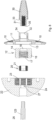
- a first embodiment of a coupling system is shown between the parts in a prosthesis for the articulation of the shoulder with component parts exploded together according to the present invention.
- the coupling system in the parts illustrated of a prosthesis for the articulation of the shoulder shown in figures 1 and 2 comprises a metal support 11 which is suitable for being pressure-inserted in a seat formed in the glenohumeral bone and fixed therein with screws (not shown) arranged in holes 10.
- the metal support 11 has been previously specifically prepared and milled.
- a pin element 12 is arranged in a hole 13 of the metal support 11. It should be noted that this coupling is effected thanks to the fact that the pin element 12 provides a conical section 14 at one end, which engages with a complementary internal conical shape of the hole 13 by means of a morse cone.
- the pin element 12 at its other end provides a cylindrical section 15 with an external knurled surface.
- this pin element 12 has a hole which passes through a section 16 corresponding to the conical section 14 and is threaded in a section 17 corresponding to the cylindrical section 15.
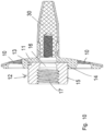
- a screw 18 is inserted in the hole 17/16 ( figure 4 ) so that the end of the screw 18 is screwed into a hole prepared with a special cutter in the scapular bone.
- a glenosphere 22 provides a pass-through axial hole 24 with sections having a differentiated diameter.
- One side facing the elements previously described provides an internal seat with an enlarged diameter 23' provided with knurling which is suitable for being inserted above and coupled with the cylindrical section 15 with an external knurled surface of the pin element 12. This causes the stable blocking of the assembly formed integral with the metal support 11, which in turn had been previously pressure-inserted in the seat formed in the glenohumeral bone.
- a safety screw 23 is screwed in, which, passing through the axial pass-through hole 24 of the glenosphere 22, is positioned in an internal threaded portion 25 of the cylindrical bush 20 ( figure 7 ) which had previously been firmly screwed into the pin element 12. It should also be noted how a head 26 of the safety screw 23 is stably arranged in a section with an enlarged diameter 27 of the axial hole 24, arranged on the opposite side of the glenosphere 22 with respect to that of the internal seat having an enlarged diameter 23' provided with knurling.
- the system according to the invention essentially comprises a metal support 11, a pin element 12, a cylindrical bush 20 and a glenosphere or hemispherical element 22 which are consecutively coupled in the sequence listed above, in addition to reciprocal constraint elements.
- FIG 7 therefore shows a first embodiment of a coupling system between the parts in a prosthesis for the articulation of the shoulder according to the present invention and how it is assembled.
- This arrangement is particularly simple and easy to assemble, and its parts are also very simple to construct.
- Figures 8 to 13 show a second embodiment of a coupling system between the parts in a prosthesis for the articulation of the shoulder according to the present invention.
- figure 8 which shows all of the components of the system forming part of this embodiment, it can be seen that in addition to the metal support 11 there is also a central peg 30 which in a first step ( figure 9 ) is coupled with the support 11. An end having a reduced diameter 31 of the peg 30 is in fact inserted into a pass-through hole 32 formed at the end of the support 11.
- this conical end 31 is inserted into and engages in the pass-through hole 32 formed in said metal support 11 having a complementary internal conical shape by means of a morse cone.
- the whole thus composed ( figure 9 ) is pressure-inserted into a seat formed in the glenohumeral bone and possibly further fixed therein with screws to the scapular bone (not shown) passing through the holes 10 of the support 11.
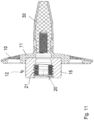
- the step for inserting the cylindrical bush 20 externally threaded in 21 is effected within the threaded section 17 of the pin element 12 with screwing ( figure 11 ). This is effected after the pin element 12, as already indicated and shown, has been made almost integral with the metal support 11.
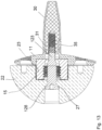
- the final positioning of the glenosphere 22 is effected on the subgroup indicated above, thus stably formed, by means of compression in axis guided with a specific tool or screwing mechanism in a guided and controlled manner, until the final arrangement has been reached, as shown in figure 12 .
- the glenosphere 22 provides that the internal seat 23' be provided with knurling which is inserted above the cylindrical section 15 with an external knurled surface of the pin element 12. This causes the stable blocking of the assembly formed integral with the metal support 11, which in turn had been previously pressure-inserted into the seat formed in the glenohumeral bone.
- a safety screw 123 is screwed in, which is longer than the previous safety screw 23.
- Said screw 123 passes through the axial pass-through hole 24 of the glenosphere 22 and then passes inside the cylindrical bush 20, inside the pin element 12. It then continues, passing through a first section of the metal support 11 and is positioned in the threaded hole 35 of the peg 30, previously arranged in the metal support 11.
- a head 126 of the safety screw 123 is stably arranged in a section with an enlarged diameter 27 of the axial hole 24.
- This screw 123 is therefore inserted through the hole of the bush 20 and is screwed stably to the threaded hole 35 of the peg 30.
- FIG 13 therefore shows a second embodiment of the coupling system between the parts in a prosthesis for the articulation of the shoulder according to the present invention and how it is assembled.
Landscapes
- Health & Medical Sciences (AREA)
- Orthopedic Medicine & Surgery (AREA)
- Cardiology (AREA)
- Oral & Maxillofacial Surgery (AREA)
- Transplantation (AREA)
- Engineering & Computer Science (AREA)
- Biomedical Technology (AREA)
- Heart & Thoracic Surgery (AREA)
- Vascular Medicine (AREA)
- Life Sciences & Earth Sciences (AREA)
- Animal Behavior & Ethology (AREA)
- General Health & Medical Sciences (AREA)
- Public Health (AREA)
- Veterinary Medicine (AREA)
- Prostheses (AREA)
Description
- The present invention is defined in claim 1 and relates to a coupling system between the parts in a prosthesis for the articulation of the shoulder.
- Various prosthetic solutions for the articulation of the shoulder are known, which have couplings between the parts formed using components coupled in different ways.
- The document
WO 2019/053576 discloses a total shoulder prosthesis where it is possible to convert from an anatomical prosthesis to a reverse prosthesis replacing only the articular components without replacing the components implanted in the humeral and scapular bone. - A prosthesis of this type is also disclosed for example in
EP1656910 . - This specific solution provides that a first articulation element and a second articulation element be used for the articulation of a humerus in a scapula of a shoulder.
- The first articulation element, for example, is at least partially concave, fixed to the humerus, and the second articulation element on the other hand is partially convex to be associated with the glenoid cavity. This second association is effected through an arrangement of metal fixing means.
- As the second articulation element comprises an external part made of or coated in plastic or ceramic material, this solution proposes the provision of an annular element made of metal arranged rigidly blocked inside said external part. And said annular element is destined for receiving a pin fixing element for connection to a support which is inserted in the glenoid cavity.
- As already mentioned, this is one of the possible forms of coupling which necessarily also involves a certain type of procedure for positioning the prosthesis.
- The general objective of the present invention is to provide a coupling system or arrangement between the parts in a prosthesis for the articulation of the shoulder of a different type in order to be able to use different types of positioning procedures in parallel, suitable for particular specific requirements.
- A further objective of the present invention is to provide a relatively stable and simple coupling system between the parts in a prosthesis for the articulation of the shoulder.
- The above-mentioned objectives are achieved by a coupling system between the parts in a prosthesis for the articulation of the shoulder produced according to independent claim 1 and the following subordinate claims.
- The structural and functional characteristics of the present invention and its advantages with respect to the known art will become even more evident from the following description, referring to the attached schematic drawings, which show an embodiment example of the same invention. In the drawings:
-
figure 1 shows a raised side section of a first embodiment of a coupling system between the parts in a prosthesis for the articulation of the shoulder with component parts exploded together according to the present invention; -
figure 2 shows some of the parts shown infigure 1 in a perspective view which is also exploded; -
figure 3 shows a first coupling step for the coupling system shown infigure 1 ; -
figure 4 shows a second coupling step for the coupling system shown infigure 1 ; -
figure 5 shows a third coupling step for the coupling system shown infigure 1 ; -
figure 6 shows a fourth coupling step for the coupling system shown infigure 1 ; -
figure 7 shows the final arrangement of the coupling system shown infigure 1 ; -
figure 8 shows a raised side section of a second embodiment of a coupling system between the parts in a prosthesis for the articulation of the shoulder with component parts exploded together; -
figure 9 shows some of the parts shown infigure 8 in a perspective view also exploded; -
figure 10 shows a first coupling step for the coupling system shown infigure 8 ; -
figure 11 shows a second coupling step for the coupling system shown infigure 8 ; -
figure 12 shows a third coupling step for the coupling system shown infigure 8 ; -
figure 13 shows the final arrangement of the coupling system shown infigure 8 . - With reference to
figures 1 to 7 , exemplary and nonlimiting, a first embodiment of a coupling system is shown between the parts in a prosthesis for the articulation of the shoulder with component parts exploded together according to the present invention. - The coupling system in the parts illustrated of a prosthesis for the articulation of the shoulder shown in
figures 1 and2 comprises ametal support 11 which is suitable for being pressure-inserted in a seat formed in the glenohumeral bone and fixed therein with screws (not shown) arranged inholes 10. Themetal support 11 has been previously specifically prepared and milled. - At this point, as shown in
figure 3 , apin element 12 is arranged in ahole 13 of themetal support 11. It should be noted that this coupling is effected thanks to the fact that thepin element 12 provides aconical section 14 at one end, which engages with a complementary internal conical shape of thehole 13 by means of a morse cone. Thepin element 12 at its other end provides acylindrical section 15 with an external knurled surface. Furthermore, thispin element 12 has a hole which passes through asection 16 corresponding to theconical section 14 and is threaded in asection 17 corresponding to thecylindrical section 15. - Once this coupling step has been carried out, a
screw 18 is inserted in thehole 17/16 (figure 4 ) so that the end of thescrew 18 is screwed into a hole prepared with a special cutter in the scapular bone. - And continuing the screwing of the
screw 18, one of itsheads 19 becomes abutted in thesection 16 of the hole of thepin element 12 and further stabilizes in compression thepin element 12 against themetal support 11. - This is followed by a further step for the insertion of a
cylindrical bush 20 externally threaded in 21 inside the threadedsection 17 of thepin element 12 with screwing; and this after thepin element 12, as specified and shown, has been made almost integral with the metal support 11 (figure 5 ). - At this point, with the subgroup indicated above thus stably formed, the final positioning of a
glenosphere 22, or hemispherical element, is effected by compression in axis guided with a specific tool or screwing mechanism in a guided and controlled manner, until the final arrangement has been reached, as shown infigure 6 . In particular, saidglenosphere 22 provides a pass-throughaxial hole 24 with sections having a differentiated diameter. One side facing the elements previously described, in fact, provides an internal seat with an enlarged diameter 23' provided with knurling which is suitable for being inserted above and coupled with thecylindrical section 15 with an external knurled surface of thepin element 12. This causes the stable blocking of the assembly formed integral with themetal support 11, which in turn had been previously pressure-inserted in the seat formed in the glenohumeral bone. - All that remains therefore is simply a last step in which a
safety screw 23 is screwed in, which, passing through the axial pass-throughhole 24 of theglenosphere 22, is positioned in an internal threadedportion 25 of the cylindrical bush 20 (figure 7 ) which had previously been firmly screwed into thepin element 12. It should also be noted how ahead 26 of thesafety screw 23 is stably arranged in a section with an enlargeddiameter 27 of theaxial hole 24, arranged on the opposite side of theglenosphere 22 with respect to that of the internal seat having an enlarged diameter 23' provided with knurling. - The system according to the invention essentially comprises a
metal support 11, apin element 12, acylindrical bush 20 and a glenosphere orhemispherical element 22 which are consecutively coupled in the sequence listed above, in addition to reciprocal constraint elements. - This arrangement shown in
figure 7 therefore shows a first embodiment of a coupling system between the parts in a prosthesis for the articulation of the shoulder according to the present invention and how it is assembled. - This arrangement is particularly simple and easy to assemble, and its parts are also very simple to construct.
-
Figures 8 to 13 show a second embodiment of a coupling system between the parts in a prosthesis for the articulation of the shoulder according to the present invention. - In this second embodiment, the same reference numbers will be used for identical elements.
- In
figure 8 which shows all of the components of the system forming part of this embodiment, it can be seen that in addition to themetal support 11 there is also acentral peg 30 which in a first step (figure 9 ) is coupled with thesupport 11. An end having a reduceddiameter 31 of thepeg 30 is in fact inserted into a pass-through hole 32 formed at the end of thesupport 11. - More specifically, this
conical end 31 is inserted into and engages in the pass-through hole 32 formed in saidmetal support 11 having a complementary internal conical shape by means of a morse cone. - The
peg 30, in its interior, also provides a threadedhole 35 at the end facing themetal support 11. The whole thus composed (figure 9 ) is pressure-inserted into a seat formed in the glenohumeral bone and possibly further fixed therein with screws to the scapular bone (not shown) passing through theholes 10 of thesupport 11. - At this point, what has already been indicated for the embodiment of
figure 3 is effected, as thesame pin element 12 is provided, which is arranged in thehole 13 of themetal support 11. Thepin element 12 through its end with theconical section 14 is therefore engaged in the complementary internal conical shape of the hole 13 (figure 10 ). And also here, it is evident that thepin element 12 at its other end provides thecylindrical section 15 with an external knurled surface. Thepin element 12 provides a pass-through hole with thesection 16 corresponding to theconical section 14 and is threaded in thesection 17 corresponding to thecylindrical section 15. - Once this coupling step has been carried out, unlike what is provided for in the first embodiment, the step for inserting the
cylindrical bush 20 externally threaded in 21 is effected within the threadedsection 17 of thepin element 12 with screwing (figure 11 ). This is effected after thepin element 12, as already indicated and shown, has been made almost integral with themetal support 11. - This is followed by a step in which the final positioning of the
glenosphere 22 is effected on the subgroup indicated above, thus stably formed, by means of compression in axis guided with a specific tool or screwing mechanism in a guided and controlled manner, until the final arrangement has been reached, as shown infigure 12 . Also in this case, in fact, theglenosphere 22 provides that the internal seat 23' be provided with knurling which is inserted above thecylindrical section 15 with an external knurled surface of thepin element 12. This causes the stable blocking of the assembly formed integral with themetal support 11, which in turn had been previously pressure-inserted into the seat formed in the glenohumeral bone. - All that remains therefore is simply a last step (shown in
figure 13 ) in which asafety screw 123 is screwed in, which is longer than theprevious safety screw 23. Saidscrew 123 passes through the axial pass-throughhole 24 of theglenosphere 22 and then passes inside thecylindrical bush 20, inside thepin element 12. It then continues, passing through a first section of themetal support 11 and is positioned in the threadedhole 35 of thepeg 30, previously arranged in themetal support 11. Here again, ahead 126 of thesafety screw 123 is stably arranged in a section with anenlarged diameter 27 of theaxial hole 24. - This
screw 123 is therefore inserted through the hole of thebush 20 and is screwed stably to the threadedhole 35 of thepeg 30. - This arrangement illustrated in
figure 13 therefore shows a second embodiment of the coupling system between the parts in a prosthesis for the articulation of the shoulder according to the present invention and how it is assembled. - It should be added that all the components described above are made of titanium alloy or, for example, the support and the peg of titanium alloy powder. An exception is the glenosphere 22 or hemispherical element which is instead preferably made entirely of UHMWPE (ISO5834/1/2) or UHMWPE containing vitamin E (ASTM F2695-12).
- The objective mentioned in the preamble of the description has thus been achieved.
- The protection scope of the present invention is defined by the enclosed claims.
Claims (4)
- A coupling system between the parts in a prosthesis for the articulation of the shoulder comprising a metal support (11), a pin element (12), a cylindrical bush (20) and a glenosphere or hemispherical element (22) which are consecutively coupled in the sequence listed above, in addition to reciprocal constraint elements, wherein said metal support (11) is provided with a hole (13),said metal support (11) and said pin element (12) are constrained with an interposed conical coupling (13,14), the pin element (12) being provided, externally at one of its ends, with a conical section (14), which engages with a complementary internal conical shape of the hole (13) by means of a morse cone,wherein said pin element (12) provides a central pass-through hole which comprises a threaded section (17),wherein said cylindrical bush (20) is externally provided with a threading (21) complementary to the threaded section (17) of the pin element (12),wherein said glenosphere or hemispherical element (22) comprises an axial pass-through hole (24) having a first diameter,and further having on one side an internal seat (23') with a second enlarged diameter provided with knurling,wherein said reciprocal constraint elements comprise at least one safety screw (23, 123) having a head (26, 126),wherein (i) said at least one safety screw (23) is adapted to be screwed into an internal threaded portion (25) of the cylindrical bush (20),or wherein (ii) the coupling system further comprises a central peg (30) adapted to be coupled to the support (11), wherein said at least one safety screw (123) is adapted to be screwed into a threaded hole (35) in the interior of the central peg (30),wherein said pin element (12) provides externally, at one end opposite to that of coupling with the metal support (11), a cylindrical section (15) with a knurled surface, said knurling of the internal seat (23') with the second enlarged diameter of the axial pass-through hole (24) of the glenosphere or hemispherical element (22) is complementary to the section (15) with a knurled surface of the pin element (12),characterized in thatthe axial pass-through hole (24) has a section with a third enlarged diameter (27) on the opposite side of the internal seat (23') having the second enlarged diameter, wherein the head (26, 126) of the at least one safety screw (23, 123) is adapted to be arranged in said section with the third enlarged diameter (27) of the axial hole (24) of the glenosphere.
- The coupling system according to claim 1 option (i), further comprising a further screw (18) which passes through the pin element (12) and blocks it against the metal support (11).
- The coupling system according to claim 1 option (ii), wherein said peg (30) has an end with a reduced diameter (31) which is inserted into a pass-through hole (32) formed in said metal support (11).
- The coupling system according to one or more of the previous claims, wherein all of said elements are made of titanium alloy with the exception of said glenosphere (22) which is made entirely of UHMWPE in accordance with IS05834/1/2 or UHMWPE containing vitamin E in accordance with ASTM F2695-12.
Applications Claiming Priority (2)
| Application Number | Priority Date | Filing Date | Title |
|---|---|---|---|
| IT202020000000925U IT202000000925U1 (en) | 2020-02-27 | 2020-02-27 | COUPLING SYSTEM BETWEEN THE PARTS IN A PROSTHESIS FOR THE SHOULDER JOINT |
| PCT/IB2021/050537 WO2021171108A1 (en) | 2020-02-27 | 2021-01-25 | Coupling system of the components of a shoulder joint prosthesis |
Publications (3)
| Publication Number | Publication Date |
|---|---|
| EP4110236A1 EP4110236A1 (en) | 2023-01-04 |
| EP4110236C0 EP4110236C0 (en) | 2024-03-06 |
| EP4110236B1 true EP4110236B1 (en) | 2024-03-06 |
Family
ID=74587081
Family Applications (1)
| Application Number | Title | Priority Date | Filing Date |
|---|---|---|---|
| EP21704610.1A Active EP4110236B1 (en) | 2020-02-27 | 2021-01-25 | Coupling system of the components of a shoulder joint prosthesis |
Country Status (6)
| Country | Link |
|---|---|
| US (1) | US20230114073A1 (en) |
| EP (1) | EP4110236B1 (en) |
| AU (1) | AU2021227608B2 (en) |
| ES (1) | ES2979365T3 (en) |
| IT (1) | IT202000000925U1 (en) |
| WO (1) | WO2021171108A1 (en) |
Families Citing this family (10)
| Publication number | Priority date | Publication date | Assignee | Title |
|---|---|---|---|---|
| FR2971144A1 (en) * | 2011-02-08 | 2012-08-10 | Tornier Sa | GLENOIDAL IMPLANT FOR SHOULDER PROSTHESIS AND SURGICAL KIT |
| EP3777777B1 (en) | 2014-01-03 | 2023-04-05 | Howmedica Osteonics Corp. | Glenoid implant for a shoulder prosthesis |
| US10722374B2 (en) | 2015-05-05 | 2020-07-28 | Tornier, Inc. | Convertible glenoid implant |
| AU2020237088B2 (en) | 2019-03-11 | 2025-09-04 | Shoulder Innovations, Inc. | Total reverse shoulder systems and methods |
| AU2020276186C1 (en) | 2019-05-13 | 2022-07-21 | Howmedica Osteonics Corp. | Glenoid baseplate and implant assemblies |
| US20220265290A1 (en) | 2019-08-09 | 2022-08-25 | Howmedica Osteonics Corp. | Apparatuses and methods for implanting glenoid prostheses |
| IL322939A (en) * | 2021-01-27 | 2025-10-01 | Skeletal Dynamics Inc | Reverse shoulder prosthesis and related methods |
| JP7620116B2 (en) | 2021-02-26 | 2025-01-22 | ハウメディカ オステオニクス コーポレイション | Glenoid implant components and instruments thereof |
| US20240307188A1 (en) * | 2021-08-12 | 2024-09-19 | Howmedica Osteonics Corp. | Fenestrated bearing glenoid component |
| EP4478993A4 (en) * | 2022-04-14 | 2026-02-18 | Howmedica Osteonics Corp | GLENOSPHERE ARRANGEMENT |
Family Cites Families (8)
| Publication number | Priority date | Publication date | Assignee | Title |
|---|---|---|---|---|
| US20030208280A1 (en) * | 2000-04-21 | 2003-11-06 | Behrooz Tohidi | Wear resistant artificial joint |
| ITUD20030094A1 (en) * | 2003-04-30 | 2004-11-01 | Lima Lto Spa | REVERSE PROSTHESIS FOR THE JOINT OF THE SHOULDER. |
| ITUD20040208A1 (en) * | 2004-11-10 | 2005-02-10 | Lima Lto Spa | REVERSE PROSTHESIS FOR THE ARTICULATION OF |
| IT1398004B1 (en) * | 2010-02-10 | 2013-02-04 | Lima Lto S P A Ora Limacorporate Spa | GLENOID SUPPORT FOR SHOULDER PROSTHESIS |
| US9931219B2 (en) * | 2014-03-07 | 2018-04-03 | Arthrosurface Incorporated | Implant and anchor assembly |
| IT201700101751A1 (en) * | 2017-09-12 | 2019-03-12 | Permedica S P A | TOTAL PROSTHETICS OF PERFECTED SHOULDER |
| US10813769B2 (en) * | 2018-07-24 | 2020-10-27 | DePuy Synthes Products, Inc. | Baseplate of a modular shoulder joint prosthesis and related methods for implanting the same |
| JP7489394B2 (en) * | 2019-01-28 | 2024-05-23 | エンコア メディカル エル ピー | Glenoid Implant |
-
2020
- 2020-02-27 IT IT202020000000925U patent/IT202000000925U1/en unknown
-
2021
- 2021-01-25 EP EP21704610.1A patent/EP4110236B1/en active Active
- 2021-01-25 AU AU2021227608A patent/AU2021227608B2/en active Active
- 2021-01-25 US US17/904,859 patent/US20230114073A1/en active Pending
- 2021-01-25 ES ES21704610T patent/ES2979365T3/en active Active
- 2021-01-25 WO PCT/IB2021/050537 patent/WO2021171108A1/en not_active Ceased
Also Published As
| Publication number | Publication date |
|---|---|
| AU2021227608A1 (en) | 2022-10-13 |
| EP4110236C0 (en) | 2024-03-06 |
| WO2021171108A1 (en) | 2021-09-02 |
| IT202000000925U1 (en) | 2021-08-27 |
| AU2021227608B2 (en) | 2025-11-20 |
| US20230114073A1 (en) | 2023-04-13 |
| ES2979365T3 (en) | 2024-09-25 |
| EP4110236A1 (en) | 2023-01-04 |
Similar Documents
| Publication | Publication Date | Title |
|---|---|---|
| AU2021227608B2 (en) | Coupling system of the components of a shoulder joint prosthesis | |
| AU2020233662B2 (en) | Improved glenoid anchor for a shoulder joint prosthesis | |
| US20230079674A1 (en) | Shoulder implants and methods of use and assembly | |
| US7753959B2 (en) | Modular center pegged glenoid | |
| US7338528B2 (en) | Humeral stem with anatomical location of taper access for fixation of humeral head | |
| US10813769B2 (en) | Baseplate of a modular shoulder joint prosthesis and related methods for implanting the same | |
| CA2629959C (en) | Base platform for an artificial joint | |
| US8632598B2 (en) | Convertible glenoid implant | |
| EP0853930B1 (en) | Offset coupling for joint prosthesis | |
| US8425614B2 (en) | Modular center pegged glenoid | |
| EP2314258B1 (en) | Modular anatomic prosthetic system | |
| US20030204269A1 (en) | Triapartite attachment mechanism and method for a modular prosthesis | |
| AU2014285740B2 (en) | Prosthesis for anatomical or reverse reconstruction of the shoulder joint | |
| JP5238345B2 (en) | Modular prosthetic component | |
| ITUD20130080A1 (en) | MODULAR HUMERAL PROSTHESIS | |
| AU2016254153A1 (en) | Threaded augmentable acetabular shell with augments | |
| US20230404767A1 (en) | Glenoid implant for reverse shoulder prosthesis | |
| AU6526999A (en) | Femoral component | |
| US20210251767A1 (en) | Systems and Methods for Reverse Arthroplasty | |
| US20240398577A1 (en) | Modular Humeral Component for Use in a Universal Shoulder Prosthesis System |
Legal Events
| Date | Code | Title | Description |
|---|---|---|---|
| STAA | Information on the status of an ep patent application or granted ep patent |
Free format text: STATUS: UNKNOWN |
|
| STAA | Information on the status of an ep patent application or granted ep patent |
Free format text: STATUS: THE INTERNATIONAL PUBLICATION HAS BEEN MADE |
|
| PUAI | Public reference made under article 153(3) epc to a published international application that has entered the european phase |
Free format text: ORIGINAL CODE: 0009012 |
|
| STAA | Information on the status of an ep patent application or granted ep patent |
Free format text: STATUS: REQUEST FOR EXAMINATION WAS MADE |
|
| 17P | Request for examination filed |
Effective date: 20220922 |
|
| AK | Designated contracting states |
Kind code of ref document: A1 Designated state(s): AL AT BE BG CH CY CZ DE DK EE ES FI FR GB GR HR HU IE IS IT LI LT LU LV MC MK MT NL NO PL PT RO RS SE SI SK SM TR |
|
| DAV | Request for validation of the european patent (deleted) | ||
| DAX | Request for extension of the european patent (deleted) | ||
| P01 | Opt-out of the competence of the unified patent court (upc) registered |
Effective date: 20230504 |
|
| GRAP | Despatch of communication of intention to grant a patent |
Free format text: ORIGINAL CODE: EPIDOSNIGR1 |
|
| STAA | Information on the status of an ep patent application or granted ep patent |
Free format text: STATUS: GRANT OF PATENT IS INTENDED |
|
| INTG | Intention to grant announced |
Effective date: 20231128 |
|
| GRAS | Grant fee paid |
Free format text: ORIGINAL CODE: EPIDOSNIGR3 |
|
| GRAA | (expected) grant |
Free format text: ORIGINAL CODE: 0009210 |
|
| STAA | Information on the status of an ep patent application or granted ep patent |
Free format text: STATUS: THE PATENT HAS BEEN GRANTED |
|
| AK | Designated contracting states |
Kind code of ref document: B1 Designated state(s): AL AT BE BG CH CY CZ DE DK EE ES FI FR GB GR HR HU IE IS IT LI LT LU LV MC MK MT NL NO PL PT RO RS SE SI SK SM TR |
|
| REG | Reference to a national code |
Ref country code: CH Ref legal event code: EP |
|
| REG | Reference to a national code |
Ref country code: DE Ref legal event code: R096 Ref document number: 602021010114 Country of ref document: DE |
|
| REG | Reference to a national code |
Ref country code: IE Ref legal event code: FG4D |
|
| U01 | Request for unitary effect filed |
Effective date: 20240321 |
|
| U07 | Unitary effect registered |
Designated state(s): AT BE BG DE DK EE FI FR IT LT LU LV MT NL PT SE SI Effective date: 20240402 |
|
| P04 | Withdrawal of opt-out of the competence of the unified patent court (upc) registered |
Effective date: 20240412 |
|
| PG25 | Lapsed in a contracting state [announced via postgrant information from national office to epo] |
Ref country code: GR Free format text: LAPSE BECAUSE OF FAILURE TO SUBMIT A TRANSLATION OF THE DESCRIPTION OR TO PAY THE FEE WITHIN THE PRESCRIBED TIME-LIMIT Effective date: 20240607 |
|
| PG25 | Lapsed in a contracting state [announced via postgrant information from national office to epo] |
Ref country code: RS Free format text: LAPSE BECAUSE OF FAILURE TO SUBMIT A TRANSLATION OF THE DESCRIPTION OR TO PAY THE FEE WITHIN THE PRESCRIBED TIME-LIMIT Effective date: 20240606 Ref country code: HR Free format text: LAPSE BECAUSE OF FAILURE TO SUBMIT A TRANSLATION OF THE DESCRIPTION OR TO PAY THE FEE WITHIN THE PRESCRIBED TIME-LIMIT Effective date: 20240306 |
|
| PG25 | Lapsed in a contracting state [announced via postgrant information from national office to epo] |
Ref country code: RS Free format text: LAPSE BECAUSE OF FAILURE TO SUBMIT A TRANSLATION OF THE DESCRIPTION OR TO PAY THE FEE WITHIN THE PRESCRIBED TIME-LIMIT Effective date: 20240606 Ref country code: NO Free format text: LAPSE BECAUSE OF FAILURE TO SUBMIT A TRANSLATION OF THE DESCRIPTION OR TO PAY THE FEE WITHIN THE PRESCRIBED TIME-LIMIT Effective date: 20240606 Ref country code: HR Free format text: LAPSE BECAUSE OF FAILURE TO SUBMIT A TRANSLATION OF THE DESCRIPTION OR TO PAY THE FEE WITHIN THE PRESCRIBED TIME-LIMIT Effective date: 20240306 Ref country code: GR Free format text: LAPSE BECAUSE OF FAILURE TO SUBMIT A TRANSLATION OF THE DESCRIPTION OR TO PAY THE FEE WITHIN THE PRESCRIBED TIME-LIMIT Effective date: 20240607 |
|
| REG | Reference to a national code |
Ref country code: ES Ref legal event code: FG2A Ref document number: 2979365 Country of ref document: ES Kind code of ref document: T3 Effective date: 20240925 |
|
| PG25 | Lapsed in a contracting state [announced via postgrant information from national office to epo] |
Ref country code: IS Free format text: LAPSE BECAUSE OF FAILURE TO SUBMIT A TRANSLATION OF THE DESCRIPTION OR TO PAY THE FEE WITHIN THE PRESCRIBED TIME-LIMIT Effective date: 20240706 |
|
| PG25 | Lapsed in a contracting state [announced via postgrant information from national office to epo] |
Ref country code: SM Free format text: LAPSE BECAUSE OF FAILURE TO SUBMIT A TRANSLATION OF THE DESCRIPTION OR TO PAY THE FEE WITHIN THE PRESCRIBED TIME-LIMIT Effective date: 20240306 |
|
| PG25 | Lapsed in a contracting state [announced via postgrant information from national office to epo] |
Ref country code: CZ Free format text: LAPSE BECAUSE OF FAILURE TO SUBMIT A TRANSLATION OF THE DESCRIPTION OR TO PAY THE FEE WITHIN THE PRESCRIBED TIME-LIMIT Effective date: 20240306 |
|
| PG25 | Lapsed in a contracting state [announced via postgrant information from national office to epo] |
Ref country code: PL Free format text: LAPSE BECAUSE OF FAILURE TO SUBMIT A TRANSLATION OF THE DESCRIPTION OR TO PAY THE FEE WITHIN THE PRESCRIBED TIME-LIMIT Effective date: 20240306 |
|
| PG25 | Lapsed in a contracting state [announced via postgrant information from national office to epo] |
Ref country code: SK Free format text: LAPSE BECAUSE OF FAILURE TO SUBMIT A TRANSLATION OF THE DESCRIPTION OR TO PAY THE FEE WITHIN THE PRESCRIBED TIME-LIMIT Effective date: 20240306 |
|
| PG25 | Lapsed in a contracting state [announced via postgrant information from national office to epo] |
Ref country code: SM Free format text: LAPSE BECAUSE OF FAILURE TO SUBMIT A TRANSLATION OF THE DESCRIPTION OR TO PAY THE FEE WITHIN THE PRESCRIBED TIME-LIMIT Effective date: 20240306 Ref country code: SK Free format text: LAPSE BECAUSE OF FAILURE TO SUBMIT A TRANSLATION OF THE DESCRIPTION OR TO PAY THE FEE WITHIN THE PRESCRIBED TIME-LIMIT Effective date: 20240306 Ref country code: RO Free format text: LAPSE BECAUSE OF FAILURE TO SUBMIT A TRANSLATION OF THE DESCRIPTION OR TO PAY THE FEE WITHIN THE PRESCRIBED TIME-LIMIT Effective date: 20240306 Ref country code: PL Free format text: LAPSE BECAUSE OF FAILURE TO SUBMIT A TRANSLATION OF THE DESCRIPTION OR TO PAY THE FEE WITHIN THE PRESCRIBED TIME-LIMIT Effective date: 20240306 Ref country code: IS Free format text: LAPSE BECAUSE OF FAILURE TO SUBMIT A TRANSLATION OF THE DESCRIPTION OR TO PAY THE FEE WITHIN THE PRESCRIBED TIME-LIMIT Effective date: 20240706 Ref country code: CZ Free format text: LAPSE BECAUSE OF FAILURE TO SUBMIT A TRANSLATION OF THE DESCRIPTION OR TO PAY THE FEE WITHIN THE PRESCRIBED TIME-LIMIT Effective date: 20240306 |
|
| REG | Reference to a national code |
Ref country code: DE Ref legal event code: R097 Ref document number: 602021010114 Country of ref document: DE |
|
| PLBE | No opposition filed within time limit |
Free format text: ORIGINAL CODE: 0009261 |
|
| STAA | Information on the status of an ep patent application or granted ep patent |
Free format text: STATUS: NO OPPOSITION FILED WITHIN TIME LIMIT |
|
| 26N | No opposition filed |
Effective date: 20241209 |
|
| U20 | Renewal fee for the european patent with unitary effect paid |
Year of fee payment: 5 Effective date: 20250115 |
|
| PG25 | Lapsed in a contracting state [announced via postgrant information from national office to epo] |
Ref country code: MC Free format text: LAPSE BECAUSE OF FAILURE TO SUBMIT A TRANSLATION OF THE DESCRIPTION OR TO PAY THE FEE WITHIN THE PRESCRIBED TIME-LIMIT Effective date: 20240306 |
|
| GBPC | Gb: european patent ceased through non-payment of renewal fee |
Effective date: 20250125 |
|
| PG25 | Lapsed in a contracting state [announced via postgrant information from national office to epo] |
Ref country code: GB Free format text: LAPSE BECAUSE OF NON-PAYMENT OF DUE FEES Effective date: 20250125 |
|
| PG25 | Lapsed in a contracting state [announced via postgrant information from national office to epo] |
Ref country code: IE Free format text: LAPSE BECAUSE OF NON-PAYMENT OF DUE FEES Effective date: 20250125 |
|
| REG | Reference to a national code |
Ref country code: CH Ref legal event code: U11 Free format text: ST27 STATUS EVENT CODE: U-0-0-U10-U11 (AS PROVIDED BY THE NATIONAL OFFICE) Effective date: 20260201 |
|
| U20 | Renewal fee for the european patent with unitary effect paid |
Year of fee payment: 6 Effective date: 20260121 |
|
| PGFP | Annual fee paid to national office [announced via postgrant information from national office to epo] |
Ref country code: ES Payment date: 20260202 Year of fee payment: 6 |
|
| PGFP | Annual fee paid to national office [announced via postgrant information from national office to epo] |
Ref country code: CH Payment date: 20260201 Year of fee payment: 6 |