EP4110128B1 - Sole structure for article of footwear - Google Patents
Sole structure for article of footwear Download PDFInfo
- Publication number
- EP4110128B1 EP4110128B1 EP21713201.8A EP21713201A EP4110128B1 EP 4110128 B1 EP4110128 B1 EP 4110128B1 EP 21713201 A EP21713201 A EP 21713201A EP 4110128 B1 EP4110128 B1 EP 4110128B1
- Authority
- EP
- European Patent Office
- Prior art keywords
- cleat
- cleats
- outsole
- major
- minor
- Prior art date
- Legal status (The legal status is an assumption and is not a legal conclusion. Google has not performed a legal analysis and makes no representation as to the accuracy of the status listed.)
- Active
Links
Images






Classifications
-
- A—HUMAN NECESSITIES
- A43—FOOTWEAR
- A43C—FASTENINGS OR ATTACHMENTS OF FOOTWEAR; LACES IN GENERAL
- A43C15/00—Non-skid devices or attachments
- A43C15/16—Studs or cleats for football or like boots
- A43C15/162—Studs or cleats for football or like boots characterised by the shape
-
- A—HUMAN NECESSITIES
- A43—FOOTWEAR
- A43B—CHARACTERISTIC FEATURES OF FOOTWEAR; PARTS OF FOOTWEAR
- A43B13/00—Soles; Sole-and-heel integral units
- A43B13/02—Soles; Sole-and-heel integral units characterised by the material
- A43B13/12—Soles with several layers of different materials
- A43B13/122—Soles with several layers of different materials characterised by the outsole or external layer
-
- A—HUMAN NECESSITIES
- A43—FOOTWEAR
- A43B—CHARACTERISTIC FEATURES OF FOOTWEAR; PARTS OF FOOTWEAR
- A43B13/00—Soles; Sole-and-heel integral units
- A43B13/02—Soles; Sole-and-heel integral units characterised by the material
- A43B13/12—Soles with several layers of different materials
- A43B13/125—Soles with several layers of different materials characterised by the midsole or middle layer
-
- A—HUMAN NECESSITIES
- A43—FOOTWEAR
- A43B—CHARACTERISTIC FEATURES OF FOOTWEAR; PARTS OF FOOTWEAR
- A43B13/00—Soles; Sole-and-heel integral units
- A43B13/14—Soles; Sole-and-heel integral units characterised by the constructive form
- A43B13/16—Pieced soles
-
- A—HUMAN NECESSITIES
- A43—FOOTWEAR
- A43B—CHARACTERISTIC FEATURES OF FOOTWEAR; PARTS OF FOOTWEAR
- A43B13/00—Soles; Sole-and-heel integral units
- A43B13/14—Soles; Sole-and-heel integral units characterised by the constructive form
- A43B13/22—Soles made slip-preventing or wear-resisting, e.g. by impregnation or spreading a wear-resisting layer
- A43B13/223—Profiled soles
-
- A—HUMAN NECESSITIES
- A43—FOOTWEAR
- A43B—CHARACTERISTIC FEATURES OF FOOTWEAR; PARTS OF FOOTWEAR
- A43B13/00—Soles; Sole-and-heel integral units
- A43B13/38—Built-in insoles joined to uppers during the manufacturing process, e.g. structural insoles; Insoles glued to shoes during the manufacturing process
- A43B13/41—Built-in insoles joined to uppers during the manufacturing process, e.g. structural insoles; Insoles glued to shoes during the manufacturing process combined with heel stiffener, toe stiffener, or shank stiffener
-
- A—HUMAN NECESSITIES
- A43—FOOTWEAR
- A43B—CHARACTERISTIC FEATURES OF FOOTWEAR; PARTS OF FOOTWEAR
- A43B3/00—Footwear characterised by the shape or the use
- A43B3/0036—Footwear characterised by the shape or the use characterised by a special shape or design
- A43B3/0042—Footwear characterised by the shape or the use characterised by a special shape or design with circular or circle shaped parts
Definitions
- the present disclosure relates generally to sole structures for articles of footwear, and more particularly to sole structures incorporating traction elements.
- Articles of footwear conventionally include an upper and a sole structure.
- the upper may be formed from any suitable material(s) to receive, secure, and support a foot on the sole structure.
- the upper may cooperate with laces, straps, or other fasteners to adjust the fit of the upper around the foot.
- Sole structures generally include a layered arrangement extending between a ground surface and the upper.
- One layer of the sole structure includes an outsole that provides abrasion-resistance and traction with the ground surface.
- the outsole may be formed from rubber or other materials that impart durability and wear-resistance, as well as enhance traction with the ground surface.
- the outsole may include one or more traction elements or cleats for engaging a ground surface.
- Another layer of the sole structure includes a midsole disposed between the outsole and the upper.
- the midsole provides cushioning for the foot and may be partially formed from a polymer foam material that compresses resiliently under an applied load to cushion the foot by attenuating ground-reaction forces.
- Sole structures may also include a comfort-enhancing insole or a sockliner located within a void proximate to the bottom portion of the upper and a strobel attached to the upper and disposed between the midsole and the insole or sockliner.
- Document US 4 194 310 A1 describes an athletic shoe with molded cleats of resilient material for use on artificial turf or other hard surfaces including first cleats provided on the bottom of the shoe sole positioned beneath the foot of the wearer and second cleats provided on both sides of the shoe.
- the second cleats are molded integral with a cover strip of resilient material bonded to the outer surface of the shoe upper at its lower edge to extend around the toe portion, along the opposite sides and around the heel portion of the shoe upper.
- Such second cleats pro-vide added traction and enable more rapid changes in running direction, for example when playing football, baseball, or soccer, especially under wet conditions.
- the cover strip may be a separate strip from the outer sole or may be a border portion formed integral with such outer sole layer of less thickness than such outer sole layer.
- the second cleats are preferably of smaller size and may be of different shape from the first cleats.
- Document US 4 689 901 A1 describes a shoe sole for enhanced turning traction and release characteristics with an instep and an out step and further having a toe section and a heel section, the toe section bearing from two to a plurality of downwardly asymmetrically extending vacuum limiting traction arrays.
- Toe traction arrays are of generally circular basis, generally concentric with a point in a vertical axis with the balance point of the shoe sole and with the asymmetric extension from a plane comprising the shoe sole affording greater angle to the instep than the out step. This differential of angle allows improved turning characteristics with less turning strain for the wearer.
- Document US 2009/056169 A1 describes a golf shoe having an outsole comprising of forward and rear base sections that are connected and molded together with an arch support shank.
- the base sections are relatively soft and made from thermoplastic polyurethane having a maximum Shore A hardness between 75 to 85.
- the shank is also made of thermoplastic polyurethane having a minimum hardness of at least 95 Shore A hardness.
- Each base section has a plurality of openings, wherein a corresponding plurality of relatively hard pods are molded, each pod of a size and configuration to fit within a corresponding opening and ex-tend at least 6.3 mm from the bottom surfaces of the base sections.
- Example configurations will now be described more fully with reference to the accompanying drawings.
- Example configurations are provided so that this disclosure will be thorough, and will fully convey the scope of the disclosure to those of ordinary skill in the art. Specific details are set forth such as examples of specific components, devices, and methods, to provide a thorough understanding of configurations of the present disclosure. It will be apparent to those of ordinary skill in the art that specific details need not be employed, that example configurations may be embodied in many different forms, and that the specific details and the example configurations should not be construed to limit the scope of the disclosure.
- first, second, third, etc. may be used herein to describe various elements, components, regions, layers and/or sections. These elements, components, regions, layers and/or sections should not be limited by these terms. These terms may be only used to distinguish one element, component, region, layer or section from another region, layer or section. Terms such as “first,” “second,” and other numerical terms do not imply a sequence or order unless clearly indicated by the context. Thus, a first element, component, region, layer or section discussed below could be termed a second element, component, region, layer or section without departing from the teachings of the example configurations.
- an article of footwear 10 includes a sole structure 100 and an upper 200. As illustrated in FIG. 6A , the article of footwear 10 may be divided into one or more regions. The regions may include a forefoot region 12, a mid-foot region 14, and a heel region 16. The forefoot region 12 may be subdivided into a toe portion 12 T corresponding with phalanges, and a ball portion 12 B associated with metatarsal bones of a foot. The mid-foot region 14 may correspond with an arch area of the foot, and the heel region 16 may correspond with rear portions of the foot, including a calcaneus bone.
- the footwear 10 may further include an anterior end 18 associated with a forward-most point of the forefoot region 12, and a posterior end 20 corresponding to a rearward-most point of the heel region 16.
- a longitudinal axis A 10 of the footwear 10 extends along a length of the footwear 10 from the anterior end 18 to the posterior end 20.
- the longitudinal axis A 10 is centrally located along the length of the footwear 10, and generally divides the footwear 10 into a lateral side 22 and a medial side 24. Accordingly, the lateral side 22 and the medial side 24 respectively correspond with opposite sides of the footwear 10 and extend through the regions 12, 14, 16.
- a longitudinal direction refers to the direction extending from the anterior end 18 to the posterior end 20, while a lateral direction refers to the direction transverse to the longitudinal direction and extending from the lateral side 22 to the medial side 24.
- the sole structure 100 of the illustrated example is formed compositely and includes a plurality of subcomponents for providing desired characteristics of cushioning, stiffness, traction, and durability.
- the sole structure 100 includes an outsole 102, a midsole 104, a shank 106, and a cradle 108.
- the midsole 104 is configured to provide one or more layers of cushioning between the upper 200 and a ground-engaging surface 26.
- the midsole 104 may include an outer casing 110 and a core 112 disposed within the casing 110, as described in greater detail below.
- the outsole 102 is configured to provide a durable ground-engaging surface for the article of footwear and includes a plurality of traction elements for interfacing with the ground surface.
- the outsole 102 includes a forefoot plate 114a disposed in the forefoot region 12 and including a first plurality of traction elements, and a heel plate 114b disposed in the heel region and including a second plurality of traction elements.
- Each of the plates 114a, 114b may be described as including a top surface 115a, 115b facing the upper 200, a bottom surface 116a, 116b formed on an opposite side of the plate 114a, 114b from the top surface 115a, 115b, and a peripheral surface 117a, 117b extending from the top surface 115a, 115b to the bottom surface 116a, 116b.
- the bottom surfaces 116a, 116b are associated with a plantar (downward-facing) portion of each of the plates 114a, 114b.
- the peripheral surfaces 117a, 117b are formed at an oblique angle relative to the bottom surfaces 116a, 116b and form an outer periphery of each plate 114a, 114b.
- the peripheral surfaces 117a, 117b flare outwardly in a direction from the bottom surfaces 116a, 116b to the top surface 115a, 115b.
- the traction elements of the outsole 102 may be described as including major cleats 118a-118n, minor cleats 120a-120h, and peripheral cleats 122a-122d.
- the major cleats 118a-118n and the minor cleats 120a-120h are formed on a plantar portion (e.g., the bottom surfaces 116a, 116b) of the outsole 102 and are configured to provide traction with the ground surface when a normal force is applied to the ground surface by the plantar surface of the sole structure 100.
- the peripheral cleats 122a-122d project outwardly from a peripheral portion of the outsole 102 (i.e., the peripheral surfaces 117a, 117b) and are configured to engage the ground surface when a lateral or angular force is applied in a direction towards the lateral side 22 of the sole structure 100. As best shown in FIG.
- the traction elements 118a-118n, 120a-120h, 122a-122d cooperate with each other to define a plurality of cleat sets including an annular cleat set 124 disposed in the ball portion 12 B , optionally on the medial side 24 of the forefoot plate 114a, a plurality of radial cleat sets 126a-126e arranged along the lateral side 22 and/or in the toe portion 12 T of the forefoot plate 114a, and a heel cleat set 128 disposed in the heel region 16 on the heel plate 114b.
- each of the major cleats 118a-118n includes at least the features described with respect to the example major cleat 118 of FIGS. 12A and 12B , unless otherwise specified.
- a height H 118 of each of the major cleats 118a-118n extends along an axis A 118 from a base 130 proximal to a bottom surface 116a, 116b of the sole structure 100 to a tip 132 disposed at an opposite end of the major cleat 118a-118n than the base 130.
- the tip 132 is defined by a substantially planar distal surface, such that the tip 132 defines a flat end at each of the major cleats 118a-118n.
- each of the major cleats 118a-118n is defined by the cooperation of a concave inner surface 134 and a convex outer surface 136, which converge with each other along a direction from the base 130 to the tip 132 to provide each of the major cleats 118a-118n with a tapering width W 118 .
- the inner surface 134 and the outer surface 136 may converge with each other at opposite ends of the major cleats 118a-118n such that the width W 118 tapers along a lengthwise direction from a central portion of each of the major cleats 118a-118n.
- the major cleats 118a-118n may be described as having a crescent-shaped cross section.
- one or more of the major cleats 118a-118n may be formed with a reinforcing rib 138 projecting radially from the concave inner surface 134.
- each of the minor cleats 120a-120h may include at least the generic features described with respect to the example minor cleat 120 of FIGS. 13A and 13B .
- a height H 120 of each of the minor cleats 120a-120h extends along an axis A 120 from a base 140 proximal to a bottom surface 116a, 116b of the sole structure 102 to an edge 142 disposed at an opposite end of the minor cleat 120a-120h than the base 140.
- the edge 142 is substantially continuous along a length of the minor cleat 120a-120h.
- An outer periphery of each of the minor cleats 120a-120h is defined by the cooperation of a concave inner surface 144 and a convex outer surface 146, which converge with each other along a direction from the base 140 to the edge 142.
- the inner surface 144 and the outer surface 146 may converge with each other at opposite ends of the minor cleats 120a-120h such that the width W 120 tapers along a lengthwise direction from a central portion of each of the minor cleats 120a-120h.
- the minor cleats 120a-120h may be described as having a crescent-shaped cross section.
- the heights H 120 of the minor cleats 120a-120h may be different from each other, the heights H 120 of all of the minor cleats 120a-120h are less than the heights H 118 of all of the major cleats 118a-118n.
- each of the peripheral cleats 122a-122d may include at least the generic features described with respect to the example peripheral cleat 122 of FIGS. 14A and 14B .
- a height H 122 of each of the peripheral cleats 122a-122d extends along an axis A 122 from a base 150 proximal to a bottom surface of the sole structure 102 to a tip 152 disposed at an opposite end of the peripheral cleat 122a-122d than the base 150.
- the peripheral cleats 122a-122d extend from the peripheral surface 117a at an oblique angle relative to the bottom surface 116a such that the tip 152 is defined by a substantially planar surface oriented at an oblique angle relative to the bottom surface 116a of the sole structure 102.
- An outer periphery of each of the peripheral cleats 122a-122d is defined by the cooperation of a convex inner surface 154 and a convex outer surface 156, which converge with each other along a direction from the base 150 to the tip 152.
- the inner surface 154 and the outer surface 156 may converge with each other at opposite ends of the peripheral cleats 122a-122d such that the width W 122 tapers along a lengthwise direction from a central portion of each of the peripheral cleats 122a-122d.
- the peripheral cleats 122a-122d may be described as having an ellipsoidal cross section.
- the cleat sets 124, 126a-126e of the forefoot plate 114a are generally arranged relative to an axis A 124 defined by the annular cleat set 124 and located in the ball portion 12 B , optionally on the medial side 24.
- the annular cleat set 124 includes a plurality of the major cleats 118g-118j and the minor cleats 120f arranged in an annular pattern about the central axis A 124 , while each of the radial cleat sets 126a-126e includes a respective series of traction elements including major cleats 118a-118e, minor cleats 120a-120e, and/or peripheral cleats 122a-122d aligned along a respective radial axis A 126a -A 126e that intersects the central axis A 124 , as described in greater detail below.
- the radial cleat sets 126a-126e are arranged in series in a radial array about the annular cleat set 124.
- the annular cleat set 124 includes an outer ring 158a including a series of the major cleats 118g-118j arranged along a first circle about the central axis A 124 .
- the major cleats 118g-118j of the outer ring 158a may be evenly spaced from each other along the circumference of the outer ring 158a.
- one or more of the major cleats 118g, 118h may include a reinforcing rib 138 extending inwardly towards the central axis A 124 , as described above.
- the annular cleat set 124 may include an inner ring 158b including a series of minor cleats 120f arranged along a second circle about the central axis A 124 .
- a diameter of the inner ring 158b is less than a diameter of the outer ring 158a, such that the inner ring 158b is concentric with and surrounded by the outer ring 158a.
- widths W 120 each of the minor cleats 120f of the inner ring 158b taper continuously from a first end to a second end along the circumference of the inner ring 158b.
- each of the minor cleats 120f tapers along the same direction (e.g., clockwise). It will be appreciated that the minor cleats 120f may taper along the opposite direction (e.g., counterclockwise) on an article of footwear 10 associated with the opposite foot (e.g., the left foot) of the user.
- the forefoot plate 114a includes a plurality of lateral radial cleat sets 126a-126d arranged along the lateral side 22 of the forefoot plate 114a.
- Each of the lateral radial cleat sets 126a-126d includes a respective major cleat 118a-118d disposed on the bottom surface 116a adjacent to the peripheral surface 117a, a series of minor cleats 120a-120d disposed on the bottom surface 116a between the respective major cleat 118a-118d and the annular cleat set 124, and a respective peripheral cleat 122a-122d disposed on the peripheral surface 117a ( FIGS.
- each lateral radial cleat set 126a-126d is arranged in series along the respective radial axis A 124a -A 124d .
- the minor cleats 120a-120d of each of the cleat sets 126a-126d are arranged in series such that sizes (e.g., height, width, and/or length) of the minor cleats 120a-120d progressively decrease along the direction of the respective radial axis A 126a -A 126d from the major cleat 118a-118d towards the annular cleat set 124.
- a minor cleat 120a-120d disposed closer to the respective major cleat 118a-118d of the radial cleat set 126a-126d will have a larger size than a minor cleat 120a-120d that is farther from the respective major cleat 118a-118d.
- an outer surface 146 of the minor cleat 120a-120d adjacent to the major cleat 118a-118d may be connected to the inner surface 134 of the respective major cleat 118a-118d by one of the reinforcing ribs 138.
- the reinforcing ribs 138 may extend between and connect successive ones of the minor cleats 120a-120d to each other.
- the lateral radial cleat sets 126a-126d include a first lateral radial cleat set 126a aligned along a first radial axis A 126a that intersects the central axis A 124 .
- the first radial axis A 126a extends at a first oblique angle relative to the longitudinal axis A 10 , along a direction from the annular cleat set 124 towards the posterior end 20 and the lateral side 22.
- a second lateral radial cleat set 126b is aligned along a second radial axis A 126 that intersects the central axis A 124 .
- the second radial axis A 126b extends towards the lateral side 22 in a direction substantially perpendicular (e.g. 90 ⁇ 5 degrees) to the longitudinal axis A 10 of the article of footwear 10.
- a third lateral radial cleat set 126c is aligned along a third radial axis A 126c that intersects the central axis A 124 and extends at a second oblique angle relative to the longitudinal axis A 10 , towards the lateral side 22 and the anterior end 18 of the sole structure 102.
- a fourth lateral radial cleat set 126d is aligned along a fourth radial axis A 126d that intersects the central axis A 124 and extends at a third oblique angle relative to the longitudinal axis A 10 towards the anterior end 18 and the lateral side 22 of the sole structure 102.
- the radial cleat sets 126a-126e may include an anterior radial cleat set 126e comprising a major cleat 118e and a series of minor cleats 120e disposed on the medial side 24 in the toe portion 12 T .
- the traction elements 118e, 120e of the anterior radial cleat set 126e are aligned along a fifth radial axis A 126e that is substantially parallel (e.g. 0 ⁇ 5 degrees) to the longitudinal axis A 10 of the article of footwear 10. As best illustrated in FIG.
- the anterior radial cleat 126e set includes a major cleat 118e disposed on the bottom surface 116a of the forefoot plate 114a adjacent to the peripheral surface 117a at the anterior end 18.
- a series of the minor cleats 120e is aligned with the major cleat 118e along the fifth radial axis A 126e .
- the minor cleats 120e progressively decrease in size along the direction of the fifth radial axis A 126e from the major cleat 118e to the annular cleat set 124.
- the forefoot plate 114a may further include a medial major cleat 118f disposed between the anterior radial cleat set 126e and the annular cleat set 124 along the peripheral surface 117a.
- the medial major cleat 118f is not associated with a cleat set, but is provided as an isolated major cleat 118f on the medial side 24 of the sole structure 102.
- the medial major cleat 118f includes a reinforcing rib 138 extending from the concave inner surface 134, and the convex outer surface 136 of the medial major cleat 118f is oriented (i.e., facing) towards the medial side 24 and the posterior end 20.
- the heel cleat set 128 includes a plurality of the major cleats 118k-118n arranged on the bottom surface 116b adjacent to the peripheral surface 117b. As shown, the convex outer surfaces 136 of each of the major cleats 118k-118n face the peripheral surface 117b. Each of the major cleats 118k-118n on the heel plate 114b includes a reinforcing rib 138 extending inwardly towards a central portion of the heel plate 114b.
- the heel cleat set 128 includes a first major cleat 118k on the lateral side adjacent to an anterior end of the heel plate 114b, a second major cleat 118l on the lateral side adjacent to a posterior end of the heel plate 114b, a third major cleat 118m on the medial side adjacent to the anterior end of the heel plate 114b, and a fourth major cleat 118n on the medial side adjacent to the posterior end of the heel plate 114b.
- the heel cleat set 128 includes an opposing pair of minor cleats 120g, 120h disposed in an interior portion of the heel plate 114b.
- a first one of the minor cleats 120g is disposed on the lateral side 22 of the heel plate 114b and a second one of the minor cleats 120h is disposed on the medial side 24 of the heel plate 114b, such that the concave inner surfaces 144 of the minor cleats 120h face each other across the longitudinal axis A 10 .
- the outsole plates 114a, 114b are formed of one or more polymeric and/or composite materials having a greater hardness than the midsole 104. While each of the outsole plates 114a, 114b may be formed as unitary bodies (i.e., single piece), the outsole plates 114a, 114b of the illustrated example are embodied as modular or composite structures having a series of subcomponents stacked in a nested arrangement to form each of the plates 114a, 114b. With particular reference to FIG.
- each of the plates 114a includes an inner skeleton 160a, 160b, an outer shell 162a, 162b, and one or more cleat inserts 164, which cooperate to define the outsole plates 114a, 114b and portions of the traction elements 118a-118n, 120a-120h, 122a-122d.
- the forefoot plate 114a includes a forefoot skeleton 160a configured to interface with an upper portion of the forefoot shell 162a to provide the forefoot plate 114a with a laminate structure in regions including the annular cleat set 124 and the radial cleat sets 126a-126f.
- the forefoot skeleton 160a is configured to nest within a recess formed in the top of the forefoot shell 162a such that the forefoot skeleton 160a and the forefoot shell 162a cooperate to form a flush top surface 115a of the forefoot plate 114a.
- portions of the traction elements 118a-118n, 120a-120h, 122a-122d formed by the shells 162a, 162b may be thin-walled bodies that include a cavity or recess 166a, 166b extending at least partially through the shell 162a, 162b.
- the recesses 166a, 166b may include a first plurality of recesses 166a formed partially through the thickness of the shell 162a, 162b in areas corresponding to upper portions of the minor cleats 120a-120h.
- bottom surfaces of the forefoot skeleton 160a and the heel skeleton 160b may include one or more protrusions 168 each corresponding to one of the recesses 166a formed in the top of the shells 162a, 162b, such that when the skeleton 160a, 160b is assembled with the shell 162a, 162b, the protrusions 168 are received within the recesses 166a to provide the respective minor cleat 120a-120h with a composite structure having an outer layer formed by the material of the shell 162a, 162b and a core formed by the material of the skeleton 160a, 160b.
- the recesses 166a, 166b of the shells 162a, 162b may also include recesses 166b formed entirely through the shells 162a, 162b at the major cleats 118a-118n.
- one or more of the major cleats 118a-118n may be formed, in part, by one of the cleat inserts 164.
- each of the inserts 164 includes a shank 170 configured to be inserted through the portion of the bottom surface 116a, 116b forming one of the major cleats 118a-118n, such that the shank 170 is disposed within the recess 166b ( FIGS. 7-10 ).
- Each of the cleat inserts 164 further includes a cap 172 disposed at an end of the shank 170 and configured to form a distal portion of the major cleat 118a-118n including the tip 132, as shown in FIGS. 3 and 7-10 . Accordingly, the major cleats 118a-118n may also be formed compositely.
- the midsole 104 includes one or more materials configured to impart properties of cushioning and resilience to the sole structure 100. While the midsole 104 may be formed as a unitary structure including a single material, the midsole 104 of the illustrated example is formed as a composite structure having the outer casing 110 and the core 112 disposed within the casing 110. The casing 110 and the core 112 may include different materials to impart different characteristics to the midsole 104.
- the casing 110 extends continuously from the anterior end 18 to the posterior end 20 and includes a top surface 174, a bottom surface 176 formed on an opposite side than the top surface 174, and a peripheral side surface 178 extending between the top surface 174 and the bottom surface 176.
- the peripheral side surface 178 defines an outer periphery of the casing 110 and the midsole 104.
- the top surface 174 may include a recess 180 configured to receive the core 112 therein, such that a top surface of the core 112 is flush and continuous with the top surface 174 of the casing 110 when the sole structure 100 is assembled.
- the recess 180 and the core 112 extend continuously from the forefoot region 12 to the heel region 16.
- a width of the core 112 and the recess 180 may extend substantially across an entire width of the casing 110 from the lateral side 22 to the medial side 24.
- the sole structure 100 further includes a shank 106 formed of a material having a greater rigidity than the midsole 104 and configured to be disposed adjacent to the bottom surface 176 of the midsole casing 110 to provide longitudinal support along the bottom of the sole structure 100.
- the shank 106 is interposed between the forefoot plate 114a and the heel plate 114b on the bottom surface 176 in the mid-foot region 14 of the sole structure 100.
- the shank 106 includes a top surface 182 that attaches to the bottom surface 176 of the midsole casing 110 and a bottom surface 184 formed on an opposite side of the shank 106 than the top surface 182.
- An outer periphery 186 of the shank 106 is configured to interface or mate with the forefoot plate 114a at an anterior end of the shank 106 and with the heel plate 114b at a posterior end of the shank 106, thereby providing a substantially continuous rigid structure along the bottom surface 176 of the midsole casing 110 from the anterior end 18 to the posterior end 20.
- the top and/or bottom surfaces 182, 184 of the shank 106 may include one or more elongate ribs 188 extending generally along the longitudinal direction (i.e., along the longitudinal axis A 10 ). Each of the ribs 188 may extend along a contoured path corresponding to a profile of the outer periphery 186 along the lateral and medial sides of the shank 106. The ribs 188 provide the shank 106 with localized areas of increased thickness to provide longitudinal stiffness to the shank 106, as desired.
- the cradle 108 of the sole structure 100 includes a top surface 190 that faces and attaches to the bottom surface 184 of the shank 106, and a bottom surface 192 formed on an opposite side of the cradle 108 than the top surface 190.
- the bottom surface 192 forms a portion of the ground-engaging surface of the sole structure 100 between bottom surface 116a of the forefoot plate 114a and bottom surface 116b of the heel plate 114b.
- the cradle 108 is configured to envelope the shank 106 in the mid-foot region 14.
- the sole structure 100 of the present disclosure provides several benefits over sole structures known in the art. For example, by providing the annular cleat set 124 and the plurality of radial cleat sets 126a-126e arranged relative to the central axis A 124 , the sole structure 100 advantageously provides desirable traction in the lateral and longitudinal directions, while allowing the sole structure 100 to rotate about the central axis A 124 when engaged with a ground surface. Additionally, the inclusion of the peripheral cleats 122a-122d along the lateral side 22 of the sole structure 100 provides improved traction to the sole structure 100 when the medial side 24 of the sole structure is lifted from the ground surface, such as when pushing off of the lateral side of the foot.
- Additional benefits of the sole structure 100 include forming the outsole 102 and the midsole 104 as composite structures. For example, by utilizing outer shells 162a, 162b and inner skeletons 160a, 160b for forming the outsole plates 114a, 114b, an exterior of the outsole 102 can be formed with a more rigid material while the interior of the outsole 102 may be more flexible or provide improved cushioning. Likewise, forming the midsole 104 as a composite structure may allow the exterior of the midsole 104 to be formed of a more durable material while the interior of the midsole 104 is formed with properties to impart desirable stiffness and/or cushioning.
Landscapes
- Chemical & Material Sciences (AREA)
- Engineering & Computer Science (AREA)
- Materials Engineering (AREA)
- Footwear And Its Accessory, Manufacturing Method And Apparatuses (AREA)
Description
- The present disclosure relates generally to sole structures for articles of footwear, and more particularly to sole structures incorporating traction elements.
- This section provides background information related to the present disclosure which is not necessarily prior art.
- Articles of footwear conventionally include an upper and a sole structure. The upper may be formed from any suitable material(s) to receive, secure, and support a foot on the sole structure. The upper may cooperate with laces, straps, or other fasteners to adjust the fit of the upper around the foot. A bottom portion of the upper, proximate to a bottom surface of the foot, attaches to the sole structure.
- Sole structures generally include a layered arrangement extending between a ground surface and the upper. One layer of the sole structure includes an outsole that provides abrasion-resistance and traction with the ground surface. The outsole may be formed from rubber or other materials that impart durability and wear-resistance, as well as enhance traction with the ground surface. The outsole may include one or more traction elements or cleats for engaging a ground surface. Another layer of the sole structure includes a midsole disposed between the outsole and the upper. The midsole provides cushioning for the foot and may be partially formed from a polymer foam material that compresses resiliently under an applied load to cushion the foot by attenuating ground-reaction forces. Sole structures may also include a comfort-enhancing insole or a sockliner located within a void proximate to the bottom portion of the upper and a strobel attached to the upper and disposed between the midsole and the insole or sockliner.
- Document
US 4 194 310 A1 describes an athletic shoe with molded cleats of resilient material for use on artificial turf or other hard surfaces including first cleats provided on the bottom of the shoe sole positioned beneath the foot of the wearer and second cleats provided on both sides of the shoe. The second cleats are molded integral with a cover strip of resilient material bonded to the outer surface of the shoe upper at its lower edge to extend around the toe portion, along the opposite sides and around the heel portion of the shoe upper. Such second cleats pro-vide added traction and enable more rapid changes in running direction, for example when playing football, baseball, or soccer, especially under wet conditions. The cover strip may be a separate strip from the outer sole or may be a border portion formed integral with such outer sole layer of less thickness than such outer sole layer. The second cleats are preferably of smaller size and may be of different shape from the first cleats. - Document
US D 844 952 S - Document
US 4 689 901 A1 describes a shoe sole for enhanced turning traction and release characteristics with an instep and an out step and further having a toe section and a heel section, the toe section bearing from two to a plurality of downwardly asymmetrically extending vacuum limiting traction arrays. Toe traction arrays are of generally circular basis, generally concentric with a point in a vertical axis with the balance point of the shoe sole and with the asymmetric extension from a plane comprising the shoe sole affording greater angle to the instep than the out step. This differential of angle allows improved turning characteristics with less turning strain for the wearer. - Document
US 2009/056169 A1 describes a golf shoe having an outsole comprising of forward and rear base sections that are connected and molded together with an arch support shank. The base sections are relatively soft and made from thermoplastic polyurethane having a maximum Shore A hardness between 75 to 85. The shank is also made of thermoplastic polyurethane having a minimum hardness of at least 95 Shore A hardness. Each base section has a plurality of openings, wherein a corresponding plurality of relatively hard pods are molded, each pod of a size and configuration to fit within a corresponding opening and ex-tend at least 6.3 mm from the bottom surfaces of the base sections. - The drawings described herein are for illustrative purposes only of selected configurations and are not intended to limit the scope of the present disclosure.
-
FIG. 1 is a bottom perspective view of an article of footwear in accordance with the claimed invention; -
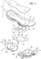
FIG. 2 is an exploded perspective view of the article of footwear ofFIG. 1 ; -
FIG. 3 is an exploded perspective view of an outsole of the article of footwear ofFIG. 1 ; -
FIG. 4 is a medial side elevation view of the article of footwear ofFIG. 1 ; -
FIG. 5 is a lateral side elevation view of the article of footwear ofFIG. 1 ; -
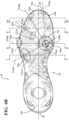
FIGS. 6A and6B are bottom plan views of the article of footwear ofFIG. 1 ; -
FIG. 7 is a cross-sectional view of the article of footwear ofFIG. 1 , taken along section line 7-7 ofFIG. 6B ; -
FIG. 8 is a cross-sectional view of the article of footwear ofFIG. 1 , taken along section line 8-8 ofFIG. 6B ; -
FIG. 9 is a cross-sectional view of the article of footwear ofFIG. 1 , taken along section line 9-9 ofFIG. 6B ; -
FIG. 10 is a cross-sectional view of the article of footwear ofFIG. 1 , taken along section line 10-10 ofFIG. 6B ; -
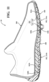
FIG. 11 is a longitudinal cross-sectional view of the article of footwear ofFIG. 1 , taken along line A10 ofFIG. 6B ; -
FIG. 12A is a plan view of an example of a major cleat of the article of footwear ofFIG. 1 , taken atarea 12A ofFIG. 6B ; -
FIG. 12B is a cross-sectional view of the example of the major cleat ofFIG. 12A , taken alongsection line 12B-12B ofFIG. 12A ; -
FIG. 13A is a plan view of an example of a minor cleat of the article of footwear ofFIG. 1 , taken atarea 13A ofFIG. 6B ; -
FIG. 13B is a cross-sectional view of the example of the minor cleat ofFIG. 13A , taken alongsection line 13B-13B ofFIG. 13A ; -
FIG. 14A is a plan view of an example of a peripheral cleat of the article of footwear ofFIG. 1 , taken arearea 14A ofFIG. 6B ; and -
FIG. 14B is a cross-sectional view of the example of the peripheral cleat ofFIG. 14A , taken alongsection line 14B-14B ofFIG. 14A . - Corresponding reference numerals indicate corresponding parts throughout the drawings.
- The claimed invention is defined by the features set forth in the appended independent claim. Particular embodiments of the claimed invention are defined by the dependent claims.
- Example configurations will now be described more fully with reference to the accompanying drawings. Example configurations are provided so that this disclosure will be thorough, and will fully convey the scope of the disclosure to those of ordinary skill in the art. Specific details are set forth such as examples of specific components, devices, and methods, to provide a thorough understanding of configurations of the present disclosure. It will be apparent to those of ordinary skill in the art that specific details need not be employed, that example configurations may be embodied in many different forms, and that the specific details and the example configurations should not be construed to limit the scope of the disclosure.
- The terminology used herein is for the purpose of describing particular exemplary configurations only and is not intended to be limiting. The terms "comprises," "comprising," "including," and "having," are inclusive and therefore specify the presence of features, steps, operations, elements, and/or components, but do not preclude the presence or addition of one or more other features, steps, operations, elements, components, and/or groups thereof. The method steps, processes, and operations described herein are not to be construed as necessarily requiring their performance in the particular order discussed or illustrated, unless specifically identified as an order of performance. Additional or alternative steps may be employed.
- When an element or layer is referred to as being "on," "engaged to," "connected to," "attached to," or "coupled to" another element or layer, it may be directly on, engaged, connected, attached, or coupled to the other element or layer, or intervening elements or layers may be present. In contrast, when an element is referred to as being "directly on," "directly engaged to," "directly connected to," "directly attached to," or "directly coupled to" another element or layer, there may be no intervening elements or layers present. Other words used to describe the relationship between elements should be interpreted in a like fashion (e.g., "between" versus "directly between," "adjacent" versus "directly adjacent," etc.). As used herein, the term "and/or" includes any and all combinations of one or more of the associated listed items.
- The terms first, second, third, etc. may be used herein to describe various elements, components, regions, layers and/or sections. These elements, components, regions, layers and/or sections should not be limited by these terms. These terms may be only used to distinguish one element, component, region, layer or section from another region, layer or section. Terms such as "first," "second," and other numerical terms do not imply a sequence or order unless clearly indicated by the context. Thus, a first element, component, region, layer or section discussed below could be termed a second element, component, region, layer or section without departing from the teachings of the example configurations.
- The details of one or more implementations of the disclosure are set forth in the accompanying drawings and the description below. Other aspects, features, and advantages will be apparent from the description and drawings, and from the claims.
- Referring to
FIGS. 1-11 , an article offootwear 10 includes asole structure 100 and an upper 200. As illustrated inFIG. 6A , the article offootwear 10 may be divided into one or more regions. The regions may include aforefoot region 12, amid-foot region 14, and aheel region 16. Theforefoot region 12 may be subdivided into atoe portion 12T corresponding with phalanges, and aball portion 12B associated with metatarsal bones of a foot. Themid-foot region 14 may correspond with an arch area of the foot, and theheel region 16 may correspond with rear portions of the foot, including a calcaneus bone. - The
footwear 10 may further include ananterior end 18 associated with a forward-most point of theforefoot region 12, and aposterior end 20 corresponding to a rearward-most point of theheel region 16. As shown inFIG. 6A , a longitudinal axis A10 of thefootwear 10 extends along a length of thefootwear 10 from theanterior end 18 to theposterior end 20. The longitudinal axis A10 is centrally located along the length of thefootwear 10, and generally divides thefootwear 10 into alateral side 22 and amedial side 24. Accordingly, thelateral side 22 and themedial side 24 respectively correspond with opposite sides of thefootwear 10 and extend through theregions anterior end 18 to theposterior end 20, while a lateral direction refers to the direction transverse to the longitudinal direction and extending from thelateral side 22 to themedial side 24. - Unlike conventional sole structures, which may have a unitary construction, the
sole structure 100 of the illustrated example is formed compositely and includes a plurality of subcomponents for providing desired characteristics of cushioning, stiffness, traction, and durability. As shown inFIG. 2 , thesole structure 100 includes anoutsole 102, amidsole 104, ashank 106, and acradle 108. Themidsole 104 is configured to provide one or more layers of cushioning between the upper 200 and a ground-engaging surface 26. Optionally, themidsole 104 may include anouter casing 110 and acore 112 disposed within thecasing 110, as described in greater detail below. Theoutsole 102 is configured to provide a durable ground-engaging surface for the article of footwear and includes a plurality of traction elements for interfacing with the ground surface. - With continued reference to
FIG. 2 , theoutsole 102 includes aforefoot plate 114a disposed in theforefoot region 12 and including a first plurality of traction elements, and aheel plate 114b disposed in the heel region and including a second plurality of traction elements. Each of theplates top surface bottom surface plate top surface peripheral surface top surface bottom surface bottom surfaces plates peripheral surfaces bottom surfaces plate peripheral surfaces bottom surfaces top surface - With reference to
FIG. 6A , the traction elements of theoutsole 102 may be described as includingmajor cleats 118a-118n,minor cleats 120a-120h, andperipheral cleats 122a-122d. Generally, themajor cleats 118a-118n and theminor cleats 120a-120h are formed on a plantar portion (e.g., thebottom surfaces outsole 102 and are configured to provide traction with the ground surface when a normal force is applied to the ground surface by the plantar surface of thesole structure 100. Theperipheral cleats 122a-122d project outwardly from a peripheral portion of the outsole 102 (i.e., theperipheral surfaces lateral side 22 of thesole structure 100. As best shown inFIG. 6B , thetraction elements 118a-118n, 120a-120h, 122a-122d cooperate with each other to define a plurality of cleat sets including an annular cleat set 124 disposed in theball portion 12B, optionally on themedial side 24 of theforefoot plate 114a, a plurality of radial cleat sets 126a-126e arranged along thelateral side 22 and/or in thetoe portion 12T of theforefoot plate 114a, and a heel cleat set 128 disposed in theheel region 16 on theheel plate 114b. - Referring now to
FIGS. 12A and 12B , a generic example 118 of one of themajor cleats 118a-118n is illustrated. While the sizing and/or the geometry of each of themajor cleats 118a-118b may be different, each of themajor cleats 118a-118n includes at least the features described with respect to the examplemajor cleat 118 ofFIGS. 12A and 12B , unless otherwise specified. As shown, a height H118 of each of themajor cleats 118a-118n extends along an axis A118 from a base 130 proximal to abottom surface sole structure 100 to atip 132 disposed at an opposite end of themajor cleat 118a-118n than thebase 130. Here, thetip 132 is defined by a substantially planar distal surface, such that thetip 132 defines a flat end at each of themajor cleats 118a-118n. An outer periphery of each of themajor cleats 118a-118n is defined by the cooperation of a concaveinner surface 134 and a convexouter surface 136, which converge with each other along a direction from the base 130 to thetip 132 to provide each of themajor cleats 118a-118n with a tapering width W118. Furthermore, theinner surface 134 and theouter surface 136 may converge with each other at opposite ends of themajor cleats 118a-118n such that the width W118 tapers along a lengthwise direction from a central portion of each of themajor cleats 118a-118n. Thus, themajor cleats 118a-118n may be described as having a crescent-shaped cross section. Optionally, one or more of themajor cleats 118a-118n may be formed with a reinforcingrib 138 projecting radially from the concaveinner surface 134. - As shown in
FIGS. 13A and 13B , a generic example 120 of one of theminor cleats 120a-120h is illustrated. While the sizing and/or the geometry of each of theminor cleats 120a-120h may be different, each of theminor cleats 120a-120h may include at least the generic features described with respect to the exampleminor cleat 120 ofFIGS. 13A and 13B . As shown, a height H120 of each of theminor cleats 120a-120h extends along an axis A120 from a base 140 proximal to abottom surface sole structure 102 to anedge 142 disposed at an opposite end of theminor cleat 120a-120h than thebase 140. Here, theedge 142 is substantially continuous along a length of theminor cleat 120a-120h. An outer periphery of each of theminor cleats 120a-120h is defined by the cooperation of a concaveinner surface 144 and a convexouter surface 146, which converge with each other along a direction from the base 140 to theedge 142. Furthermore, theinner surface 144 and theouter surface 146 may converge with each other at opposite ends of theminor cleats 120a-120h such that the width W120 tapers along a lengthwise direction from a central portion of each of theminor cleats 120a-120h. Thus, theminor cleats 120a-120h may be described as having a crescent-shaped cross section. While the heights H120 of theminor cleats 120a-120h may be different from each other, the heights H120 of all of theminor cleats 120a-120h are less than the heights H118 of all of themajor cleats 118a-118n. - As shown in
FIGS. 14A and 14B , a generic example 122 of one of theperipheral cleats 122a-122d is illustrated. While the sizing and/or geometry of each of theperipheral cleats 122a-122d may be different, each of theperipheral cleats 122a-122d may include at least the generic features described with respect to the exampleperipheral cleat 122 ofFIGS. 14A and 14B . As shown, a height H122 of each of theperipheral cleats 122a-122d extends along an axis A122 from a base 150 proximal to a bottom surface of thesole structure 102 to atip 152 disposed at an opposite end of theperipheral cleat 122a-122d than thebase 150. Unlike themajor cleats 118a-118n, which extend substantially perpendicular from thebottom surface sole structure 102, theperipheral cleats 122a-122d extend from theperipheral surface 117a at an oblique angle relative to thebottom surface 116a such that thetip 152 is defined by a substantially planar surface oriented at an oblique angle relative to thebottom surface 116a of thesole structure 102. An outer periphery of each of theperipheral cleats 122a-122d is defined by the cooperation of a convex inner surface 154 and a convexouter surface 156, which converge with each other along a direction from the base 150 to thetip 152. Furthermore, the inner surface 154 and theouter surface 156 may converge with each other at opposite ends of theperipheral cleats 122a-122d such that the width W122 tapers along a lengthwise direction from a central portion of each of theperipheral cleats 122a-122d. Thus, theperipheral cleats 122a-122d may be described as having an ellipsoidal cross section. - Referring again to
FIG. 6B , the cleat sets 124, 126a-126e of theforefoot plate 114a are generally arranged relative to an axis A124 defined by the annular cleat set 124 and located in theball portion 12B, optionally on themedial side 24. More particularly, the annular cleat set 124 includes a plurality of themajor cleats 118g-118j and theminor cleats 120f arranged in an annular pattern about the central axis A124, while each of the radial cleat sets 126a-126e includes a respective series of traction elements includingmajor cleats 118a-118e,minor cleats 120a-120e, and/orperipheral cleats 122a-122d aligned along a respective radial axis A126a-A126e that intersects the central axis A124, as described in greater detail below. Thus, the radial cleat sets 126a-126e are arranged in series in a radial array about the annular cleat set 124. - With continued reference to
FIGS. 6A and6B , the annular cleat set 124 includes anouter ring 158a including a series of themajor cleats 118g-118j arranged along a first circle about the central axis A124. Here, themajor cleats 118g-118j of theouter ring 158a may be evenly spaced from each other along the circumference of theouter ring 158a. Optionally, one or more of themajor cleats rib 138 extending inwardly towards the central axis A124, as described above. - In addition to the
outer ring 158a, the annular cleat set 124 may include aninner ring 158b including a series ofminor cleats 120f arranged along a second circle about the central axis A124. As shown, a diameter of theinner ring 158b is less than a diameter of theouter ring 158a, such that theinner ring 158b is concentric with and surrounded by theouter ring 158a. In theinner ring 158b, widths W120 each of theminor cleats 120f of theinner ring 158b taper continuously from a first end to a second end along the circumference of theinner ring 158b. As shown, each of theminor cleats 120f tapers along the same direction (e.g., clockwise). It will be appreciated that theminor cleats 120f may taper along the opposite direction (e.g., counterclockwise) on an article offootwear 10 associated with the opposite foot (e.g., the left foot) of the user. - Referring still to
FIGS. 6A and6B , theforefoot plate 114a includes a plurality of lateral radial cleat sets 126a-126d arranged along thelateral side 22 of theforefoot plate 114a. Each of the lateral radial cleat sets 126a-126d includes a respectivemajor cleat 118a-118d disposed on thebottom surface 116a adjacent to theperipheral surface 117a, a series ofminor cleats 120a-120d disposed on thebottom surface 116a between the respectivemajor cleat 118a-118d and the annular cleat set 124, and a respectiveperipheral cleat 122a-122d disposed on theperipheral surface 117a (FIGS. 7-10 ), outwardly of the respectivemajor cleat 118a-118d. Themajor cleat 118a-118d, theminor cleats 120a-120d, and theperipheral cleats 122a-122d of each lateralradial cleat set 126a-126d are arranged in series along the respective radial axis A124a-A124d. - As shown, the
minor cleats 120a-120d of each of the cleat sets 126a-126d are arranged in series such that sizes (e.g., height, width, and/or length) of theminor cleats 120a-120d progressively decrease along the direction of the respective radial axis A126a-A126d from themajor cleat 118a-118d towards the annular cleat set 124. In other words, aminor cleat 120a-120d disposed closer to the respectivemajor cleat 118a-118d of theradial cleat set 126a-126d will have a larger size than aminor cleat 120a-120d that is farther from the respectivemajor cleat 118a-118d. In each of the lateral radial cleat sets 126a-126d, anouter surface 146 of theminor cleat 120a-120d adjacent to themajor cleat 118a-118d may be connected to theinner surface 134 of the respectivemajor cleat 118a-118d by one of the reinforcingribs 138. Optionally, the reinforcingribs 138 may extend between and connect successive ones of theminor cleats 120a-120d to each other. - As shown in
FIG. 6B , the lateral radial cleat sets 126a-126d include a first lateral radial cleat set 126a aligned along a first radial axis A126a that intersects the central axis A124. In the illustrated example, the first radial axis A126a extends at a first oblique angle relative to the longitudinal axis A10, along a direction from the annular cleat set 124 towards theposterior end 20 and thelateral side 22. A second lateral radial cleat set 126b is aligned along a second radial axis A126 that intersects the central axis A124. Here, the second radial axis A126b extends towards thelateral side 22 in a direction substantially perpendicular (e.g. 90 ± 5 degrees) to the longitudinal axis A10 of the article offootwear 10. A third lateral radial cleat set 126c is aligned along a third radial axis A126c that intersects the central axis A124 and extends at a second oblique angle relative to the longitudinal axis A10, towards thelateral side 22 and theanterior end 18 of thesole structure 102. A fourth lateral radial cleat set 126d is aligned along a fourth radial axis A126d that intersects the central axis A124 and extends at a third oblique angle relative to the longitudinal axis A10 towards theanterior end 18 and thelateral side 22 of thesole structure 102. - In addition to the lateral radial cleat sets 126a-126d, which each includes a
peripheral cleat 122a-122d, the radial cleat sets 126a-126e may include an anteriorradial cleat set 126e comprising amajor cleat 118e and a series ofminor cleats 120e disposed on themedial side 24 in thetoe portion 12T. As shown, thetraction elements footwear 10. As best illustrated inFIG. 6A , the anteriorradial cleat 126e set includes amajor cleat 118e disposed on thebottom surface 116a of theforefoot plate 114a adjacent to theperipheral surface 117a at theanterior end 18. A series of theminor cleats 120e is aligned with themajor cleat 118e along the fifth radial axis A126e. As discussed above with respect to the lateral radial cleat sets 126a-126d, theminor cleats 120e progressively decrease in size along the direction of the fifth radial axis A126e from themajor cleat 118e to the annular cleat set 124. - The
forefoot plate 114a may further include a medialmajor cleat 118f disposed between the anterior radial cleat set 126e and the annular cleat set 124 along theperipheral surface 117a. Here, the medialmajor cleat 118f is not associated with a cleat set, but is provided as an isolatedmajor cleat 118f on themedial side 24 of thesole structure 102. As shown, the medialmajor cleat 118f includes a reinforcingrib 138 extending from the concaveinner surface 134, and the convexouter surface 136 of the medialmajor cleat 118f is oriented (i.e., facing) towards themedial side 24 and theposterior end 20. - Referring now to the
heel plate 114b shown inFIGS. 6A and6B , the heel cleat set 128 includes a plurality of themajor cleats 118k-118n arranged on thebottom surface 116b adjacent to theperipheral surface 117b. As shown, the convexouter surfaces 136 of each of themajor cleats 118k-118n face theperipheral surface 117b. Each of themajor cleats 118k-118n on theheel plate 114b includes a reinforcingrib 138 extending inwardly towards a central portion of theheel plate 114b. As shown, the heel cleat set 128 includes a firstmajor cleat 118k on the lateral side adjacent to an anterior end of theheel plate 114b, a second major cleat 118l on the lateral side adjacent to a posterior end of theheel plate 114b, a thirdmajor cleat 118m on the medial side adjacent to the anterior end of theheel plate 114b, and a fourth major cleat 118n on the medial side adjacent to the posterior end of theheel plate 114b. - In addition to the
major cleats 118k-118n, the heel cleat set 128 includes an opposing pair ofminor cleats heel plate 114b. For example, a first one of theminor cleats 120g is disposed on thelateral side 22 of theheel plate 114b and a second one of theminor cleats 120h is disposed on themedial side 24 of theheel plate 114b, such that the concaveinner surfaces 144 of theminor cleats 120h face each other across the longitudinal axis A10. - Generally, the
outsole plates midsole 104. While each of theoutsole plates outsole plates plates FIG. 3 , each of theplates 114a includes aninner skeleton outer shell outsole plates traction elements 118a-118n, 120a-120h, 122a-122d. - With continued reference to
FIG. 3 , theforefoot plate 114a includes aforefoot skeleton 160a configured to interface with an upper portion of theforefoot shell 162a to provide theforefoot plate 114a with a laminate structure in regions including the annular cleat set 124 and the radial cleat sets 126a-126f. As shown inFIG. 2 , theforefoot skeleton 160a is configured to nest within a recess formed in the top of theforefoot shell 162a such that theforefoot skeleton 160a and theforefoot shell 162a cooperate to form a flushtop surface 115a of theforefoot plate 114a. - With continued reference to
FIG. 3 , in some examples, portions of thetraction elements 118a-118n, 120a-120h, 122a-122d formed by theshells recess shell FIGS. 7-10 , therecesses recesses 166a formed partially through the thickness of theshell minor cleats 120a-120h. Here, bottom surfaces of theforefoot skeleton 160a and theheel skeleton 160b may include one ormore protrusions 168 each corresponding to one of therecesses 166a formed in the top of theshells skeleton shell protrusions 168 are received within therecesses 166a to provide the respectiveminor cleat 120a-120h with a composite structure having an outer layer formed by the material of theshell skeleton - The
recesses shells recesses 166b formed entirely through theshells major cleats 118a-118n. Here, one or more of themajor cleats 118a-118n may be formed, in part, by one of the cleat inserts 164. As shown inFIG. 3 , each of theinserts 164 includes ashank 170 configured to be inserted through the portion of thebottom surface major cleats 118a-118n, such that theshank 170 is disposed within therecess 166b (FIGS. 7-10 ). Each of the cleat inserts 164 further includes acap 172 disposed at an end of theshank 170 and configured to form a distal portion of themajor cleat 118a-118n including thetip 132, as shown inFIGS. 3 and7-10 . Accordingly, themajor cleats 118a-118n may also be formed compositely. - Referring again to
FIG. 2 , themidsole 104 includes one or more materials configured to impart properties of cushioning and resilience to thesole structure 100. While themidsole 104 may be formed as a unitary structure including a single material, themidsole 104 of the illustrated example is formed as a composite structure having theouter casing 110 and thecore 112 disposed within thecasing 110. Thecasing 110 and thecore 112 may include different materials to impart different characteristics to themidsole 104. - As shown in
FIG. 2 , thecasing 110 extends continuously from theanterior end 18 to theposterior end 20 and includes atop surface 174, abottom surface 176 formed on an opposite side than thetop surface 174, and aperipheral side surface 178 extending between thetop surface 174 and thebottom surface 176. Theperipheral side surface 178 defines an outer periphery of thecasing 110 and themidsole 104. As shown, thetop surface 174 may include arecess 180 configured to receive thecore 112 therein, such that a top surface of thecore 112 is flush and continuous with thetop surface 174 of thecasing 110 when thesole structure 100 is assembled. Therecess 180 and thecore 112 extend continuously from theforefoot region 12 to theheel region 16. As shown, a width of thecore 112 and therecess 180 may extend substantially across an entire width of thecasing 110 from thelateral side 22 to themedial side 24. - The
sole structure 100 further includes ashank 106 formed of a material having a greater rigidity than themidsole 104 and configured to be disposed adjacent to thebottom surface 176 of themidsole casing 110 to provide longitudinal support along the bottom of thesole structure 100. In the illustrated example, theshank 106 is interposed between theforefoot plate 114a and theheel plate 114b on thebottom surface 176 in themid-foot region 14 of thesole structure 100. - The
shank 106 includes atop surface 182 that attaches to thebottom surface 176 of themidsole casing 110 and abottom surface 184 formed on an opposite side of theshank 106 than thetop surface 182. Anouter periphery 186 of theshank 106 is configured to interface or mate with theforefoot plate 114a at an anterior end of theshank 106 and with theheel plate 114b at a posterior end of theshank 106, thereby providing a substantially continuous rigid structure along thebottom surface 176 of themidsole casing 110 from theanterior end 18 to theposterior end 20. In some examples, the top and/orbottom surfaces shank 106 may include one or moreelongate ribs 188 extending generally along the longitudinal direction (i.e., along the longitudinal axis A10). Each of theribs 188 may extend along a contoured path corresponding to a profile of theouter periphery 186 along the lateral and medial sides of theshank 106. Theribs 188 provide theshank 106 with localized areas of increased thickness to provide longitudinal stiffness to theshank 106, as desired. - Referring still to
FIG. 2 , thecradle 108 of thesole structure 100 includes atop surface 190 that faces and attaches to thebottom surface 184 of theshank 106, and abottom surface 192 formed on an opposite side of thecradle 108 than thetop surface 190. Thebottom surface 192 forms a portion of the ground-engaging surface of thesole structure 100 betweenbottom surface 116a of theforefoot plate 114a andbottom surface 116b of theheel plate 114b. Thecradle 108 is configured to envelope theshank 106 in themid-foot region 14. - The
sole structure 100 of the present disclosure provides several benefits over sole structures known in the art. For example, by providing the annular cleat set 124 and the plurality of radial cleat sets 126a-126e arranged relative to the central axis A124, thesole structure 100 advantageously provides desirable traction in the lateral and longitudinal directions, while allowing thesole structure 100 to rotate about the central axis A124 when engaged with a ground surface. Additionally, the inclusion of theperipheral cleats 122a-122d along thelateral side 22 of thesole structure 100 provides improved traction to thesole structure 100 when themedial side 24 of the sole structure is lifted from the ground surface, such as when pushing off of the lateral side of the foot. - Additional benefits of the
sole structure 100 include forming theoutsole 102 and themidsole 104 as composite structures. For example, by utilizingouter shells inner skeletons outsole plates outsole 102 can be formed with a more rigid material while the interior of theoutsole 102 may be more flexible or provide improved cushioning. Likewise, forming themidsole 104 as a composite structure may allow the exterior of themidsole 104 to be formed of a more durable material while the interior of themidsole 104 is formed with properties to impart desirable stiffness and/or cushioning. - The foregoing description has been provided for purposes of illustration and description. It is not intended to be exhaustive or to limit the disclosure. Individual elements or features of a particular configuration are generally not limited to that particular configuration, but, where applicable, are interchangeable and can be used in a selected configuration, even if not specifically shown or described. The same may also be varied in many ways. Such variations are not to be regarded as a departure from the disclosure, and all such modifications are intended to be included within the scope of the disclosure.
Claims (9)
- An outsole (102) for an article of footwear (10), the outsole (102) having a plantar surface and a peripheral surface (117a) surrounding the plantar surface and comprising:an annular cleat set (124) including a first plurality of traction elements (118g-118j, 120f) arranged in series about a central axis (A124) on the plantar surface; andone or more radial cleat sets (126a-126e) each including a second plurality of the traction elements (118a-118d, 120a-120d, 122a-122d) aligned along a respective radial axis (A126a-A126d) intersecting the central axis (A124), at least one of the second plurality of the traction elements (118a-118d, 120a-120d, 122a-122d) including a peripheral cleat (122a-122d) formed on the peripheral surface (117a),wherein the annular cleat set (124) is disposed in a ball portion (12B) of the outsole,wherein the first plurality of traction elements (118g-118j, 120f) includes a plurality of major cleats (118g-118j) and a plurality of minor cleats (120f),wherein the major cleats (118g-118j) have a greater height than the minor cleats (120f),wherein the one or more radial cleat sets (126a-126e) includes one or more lateral radial cleat sets (126a-126d) disposed adjacent to a lateral side (22) of the outsole (102),wherein the second plurality of the traction elements (118a-118d, 120a-120d, 122a-122d) of each of the one or more lateral radial cleat sets further includes a plurality of minor cleats (120a-120d) disposed on the plantar surface, and a major cleat (118a-118d) disposed on the plantar surface between the peripheral cleat (122a-122d) and the plurality of minor cleats (120a-120d), andwherein the minor cleats (120a-120d) of each of the cleat sets (126a-126d) are arranged in series such that sizes of the minor cleats (120a-120d) progressively decrease along a direction of the respective radial axis (A126a-A126d) from the major cleat (118a-118d) towards the annular cleat set (124).
- The outsole (102) of Claim 1, wherein the annular cleat set (124) is disposed on a medial side (24) of the outsole (102).
- The outsole (102) of any of Claims 1 or 2, wherein the annular cleat set (124) is disposed in a forefoot region (12) of the outsole (102).
- The outsole (102) of Claim 1, wherein the plurality of major cleats (118g-118j) is arranged in a first ring (158a) about the central axis (A124) and the plurality of minor cleats (120f) is arranged in a second ring (158b) about the central axis (A124).
- The outsole (102) of Claim 4, wherein the first ring (158a) has a larger diameter than the second ring (158b).
- The outsole (102) of any of Claims 1-5, wherein one or more of the major cleats (118g-118j) includes a reinforcing rib extending toward the central axis (A124).
- The outsole (102) of any of Claims 1-6, wherein a width of each of the major cleats (118g-118j) and each of the minor cleats (120f) tapers.
- The outsole (102) of any of Claims 1 to 7, wherein the one or more lateral radial cleat sets (126a-126d) is disposed in a forefoot region (12) of the outsole (102).
- The outsole (102) of any of Claims 1 to 8, wherein the one or more lateral radial cleat sets (126a-126d) includes a first lateral radial cleat set disposed in ball portion (12B) of the outsole (102) and a second lateral radial cleat set disposed in a toe portion (12T) of the outsole (102).
Applications Claiming Priority (3)
| Application Number | Priority Date | Filing Date | Title |
|---|---|---|---|
| US202062980606P | 2020-02-24 | 2020-02-24 | |
| US17/183,281 US11751639B2 (en) | 2020-02-24 | 2021-02-23 | Sole structure for article of footwear |
| PCT/US2021/019343 WO2021173619A1 (en) | 2020-02-24 | 2021-02-24 | Sole structure for article of footwear |
Publications (2)
| Publication Number | Publication Date |
|---|---|
| EP4110128A1 EP4110128A1 (en) | 2023-01-04 |
| EP4110128B1 true EP4110128B1 (en) | 2024-04-10 |
Family
ID=77365071
Family Applications (1)
| Application Number | Title | Priority Date | Filing Date |
|---|---|---|---|
| EP21713201.8A Active EP4110128B1 (en) | 2020-02-24 | 2021-02-24 | Sole structure for article of footwear |
Country Status (5)
| Country | Link |
|---|---|
| US (3) | US11751639B2 (en) |
| EP (1) | EP4110128B1 (en) |
| JP (1) | JP7543421B2 (en) |
| CN (1) | CN115443083B (en) |
| WO (1) | WO2021173619A1 (en) |
Families Citing this family (48)
| Publication number | Priority date | Publication date | Assignee | Title |
|---|---|---|---|---|
| US20210401124A1 (en) * | 2018-09-07 | 2021-12-30 | Chih-Fang Lo | Hiking shoes with anti-slip spikes |
| US12550969B2 (en) | 2018-09-07 | 2026-02-17 | Acushnet Company | Golf shoes having multi-surface traction outsoles |
| FR3094872B1 (en) * | 2019-04-10 | 2021-03-19 | Salomon Sas | Sports shoe |
| NL2023135B1 (en) * | 2019-05-15 | 2020-12-01 | Anbo Amersfoort B V | Shoe sole assembly, shoe, and method of manufacturing a shoe |
| USD884326S1 (en) * | 2019-08-16 | 2020-05-19 | Nike, Inc. | Shoe |
| USD971571S1 (en) | 2020-04-09 | 2022-12-06 | Under Armour, Inc. | Sole structure |
| US20220225731A1 (en) * | 2020-08-03 | 2022-07-21 | Hafia Salum Mkumba | Footwear midsole comprising a support and one or more internal bladders |
| US11957216B2 (en) | 2020-09-11 | 2024-04-16 | Nike, Inc. | Sole structure for article of footwear |
| USD1031224S1 (en) * | 2020-09-20 | 2024-06-18 | Under Armour, Inc. | Sole structure |
| USD990132S1 (en) * | 2021-02-26 | 2023-06-27 | Nike, Inc. | Shoe |
| USD990117S1 (en) * | 2021-02-26 | 2023-06-27 | Nike, Inc. | Shoe |
| USD948856S1 (en) * | 2021-03-31 | 2022-04-19 | Nike, Inc. | Shoe |
| USD948855S1 (en) * | 2021-03-31 | 2022-04-19 | Nike, Inc. | Shoe |
| USD946874S1 (en) * | 2021-05-17 | 2022-03-29 | Nike, Inc. | Shoe |
| USD948187S1 (en) * | 2021-06-09 | 2022-04-12 | Nike, Inc. | Shoe |
| USD949530S1 (en) * | 2021-06-17 | 2022-04-26 | Nike, Inc. | Shoe |
| USD956401S1 (en) * | 2021-06-17 | 2022-07-05 | Nike, Inc. | Shoe |
| USD955097S1 (en) * | 2021-06-17 | 2022-06-21 | Nike, Inc. | Shoe |
| USD955096S1 (en) * | 2021-06-17 | 2022-06-21 | Nike, Inc. | Shoe |
| US11819088B2 (en) | 2021-08-09 | 2023-11-21 | Puma SE | Outsole pattern for an article of footwear |
| USD1078248S1 (en) | 2021-08-09 | 2025-06-10 | Puma SE | Shoe sole |
| USD1033844S1 (en) * | 2021-09-03 | 2024-07-09 | Nike, Inc. | Shoe |
| USD1033845S1 (en) * | 2021-09-03 | 2024-07-09 | Nike, Inc. | Shoe |
| EP4408233A1 (en) * | 2021-10-01 | 2024-08-07 | Nike Innovate C.V. | Cleat structure for article of footwear |
| USD975976S1 (en) * | 2021-10-15 | 2023-01-24 | Nike, Inc. | Shoe |
| USD968064S1 (en) * | 2021-10-15 | 2022-11-01 | Nike, Inc. | Shoe |
| USD971570S1 (en) * | 2021-10-15 | 2022-12-06 | Nike, Inc. | Shoe |
| USD968062S1 (en) * | 2021-10-15 | 2022-11-01 | Nike, Inc. | Shoe |
| USD972265S1 (en) * | 2021-12-16 | 2022-12-13 | Nike, Inc. | Shoe |
| USD1033833S1 (en) * | 2021-12-22 | 2024-07-09 | Nike, Inc. | Shoe |
| USD1032161S1 (en) * | 2021-12-22 | 2024-06-25 | Nike, Inc. | Shoe |
| USD1031226S1 (en) * | 2021-12-22 | 2024-06-18 | Nike, Inc. | Shoe |
| US12349768B2 (en) | 2022-02-09 | 2025-07-08 | Nike, Inc. | Cleat structure for article of footwear |
| WO2023154798A1 (en) * | 2022-02-09 | 2023-08-17 | Nike Innovate C.V. | Cleat structure for article of footwear |
| DE102022202302A1 (en) * | 2022-03-08 | 2023-09-14 | Adidas Ag | Outsole for a shoe, in particular for a football shoe, shoe with such an outsole, and method for producing such items |
| EP4493015A4 (en) * | 2022-03-14 | 2025-11-26 | Hbn Shoe Llc | STOLLEN SHOE |
| USD980605S1 (en) * | 2022-05-13 | 2023-03-14 | Nike, Inc. | Shoe |
| JP2024039325A (en) * | 2022-09-09 | 2024-03-22 | 株式会社アシックス | shoes |
| USD1000794S1 (en) * | 2023-01-05 | 2023-10-10 | Nike, Inc. | Shoe |
| USD1000793S1 (en) * | 2023-01-05 | 2023-10-10 | Nike, Inc. | Shoe |
| USD1000792S1 (en) * | 2023-01-05 | 2023-10-10 | Nike, Inc. | Shoe |
| USD1000791S1 (en) * | 2023-01-05 | 2023-10-10 | Nike, Inc. | Shoe |
| US12628907B2 (en) | 2023-04-12 | 2026-05-19 | Acushnet Company | Golf shoe with traction elements |
| US20250134205A1 (en) * | 2023-10-31 | 2025-05-01 | Vionic Group LLC | Shoe sole with improved roll stability |
| EP4552522A1 (en) * | 2023-11-09 | 2025-05-14 | Pascal Chenut | Outsole for shoes with skid stabilization |
| USD1068222S1 (en) | 2024-04-12 | 2025-04-01 | Athletic Propulsion Labs LLC | Footwear with full-length midsole and cupsole |
| US12089689B1 (en) * | 2024-04-12 | 2024-09-17 | Athletic Propulsion Labs LLC | Footwear with full-length midsole and hollow cupsole |
| USD1121944S1 (en) * | 2025-02-27 | 2026-04-14 | Nike, Inc. | Shoe |
Family Cites Families (56)
| Publication number | Priority date | Publication date | Assignee | Title |
|---|---|---|---|---|
| US1972249A (en) | 1930-02-19 | 1934-09-04 | Schneider Heinrich | Shoe |
| US2095095A (en) | 1935-03-01 | 1937-10-05 | Spalding & Bros Ag | Spike for golf shoes |
| US3082549A (en) | 1962-05-01 | 1963-03-26 | Aladino W Dolceamore | Slanted cleat assembly for athletic shoes |
| US3463165A (en) | 1967-05-29 | 1969-08-26 | Joseph P Goodman | Orthopedic shoe |
| US4067123A (en) | 1977-01-31 | 1978-01-10 | Hyde Athletic Industries, Inc. | Sole construction |
| US4194310A (en) | 1978-10-30 | 1980-03-25 | Brs, Inc. | Athletic shoe for artificial turf with molded cleats on the sides thereof |
| DE3032268A1 (en) | 1980-08-27 | 1982-04-08 | Puma-Sportschuhfabriken Rudolf Dassler Kg, 8522 Herzogenaurach | OUTER SOLE FOR SPORTSHOES, MADE OF RUBBER OR OTHER MATERIAL WITH RUBBER-ELASTIC PROPERTIES |
| US4550510A (en) * | 1981-04-03 | 1985-11-05 | Pensa, Inc. | Basketball shoe sole |
| DE3127793C1 (en) * | 1981-07-14 | 1983-01-13 | Michael 5100 Aachen Schmohl | Continuous outsole for sports shoes made of elastic material for sports shoes with a tread pattern |
| US4670997A (en) * | 1984-03-23 | 1987-06-09 | Stanley Beekman | Athletic shoe sole |
| US4586274A (en) * | 1984-06-11 | 1986-05-06 | Blair Roy D | Athletic shoe cleats for artificial turf |
| US4689901A (en) * | 1984-10-19 | 1987-09-01 | Frederick Ihlenburg | Reduced torsion resistance athletic shoe sole |
| USD295231S (en) * | 1985-12-30 | 1988-04-19 | Genesco, Inc. | Baseball shoe sole |
| DE8908099U1 (en) * | 1989-07-03 | 1989-08-10 | Lowa-Schuhfabrik Lorenz Wagner GmbH & Co KG, 8069 Jetzendorf | Shoe sole with slats |
| US5201126A (en) * | 1989-09-15 | 1993-04-13 | Tanel Corporation | Cleated sole for an athletic shoe |
| USD376683S (en) | 1995-08-25 | 1996-12-24 | Adidas Ag | Outsole for an athletic shoe |
| US6101746A (en) * | 1996-08-23 | 2000-08-15 | Evans; Anthony | Footwear |
| US5782017A (en) * | 1996-11-18 | 1998-07-21 | Maven Golf Products Llc | Coupling device for a tread insert |
| US6041526A (en) * | 1997-03-11 | 2000-03-28 | Trisport Limited | Ground-gripping elements for shoe soles |
| US6016613A (en) * | 1997-11-05 | 2000-01-25 | Nike International Ltd. | Golf shoe outsole with pivot control traction elements |
| USD416673S (en) | 1998-06-26 | 1999-11-23 | Rodney Menke | Golf shoe spike |
| US6289611B1 (en) * | 1999-05-28 | 2001-09-18 | Spalding Sports Worldwide, Inc. | Golf shoe outsole with bio-mechanically positioned wear bars |
| JP3634682B2 (en) * | 1999-08-18 | 2005-03-30 | 住友ゴム工業株式会社 | shoes |
| JP3831686B2 (en) * | 2001-06-07 | 2006-10-11 | 美津濃株式会社 | Sport shoe sole assembly |
| US7143529B2 (en) * | 2002-01-14 | 2006-12-05 | Acushnet Company | Torsion management outsoles and shoes including such outsoles |
| US6834446B2 (en) | 2002-08-27 | 2004-12-28 | Softspikes, Llc | Indexable shoe cleat with improved traction |
| US20040181974A1 (en) * | 2003-03-20 | 2004-09-23 | Robinson Douglas K. | Dual density thermoplastic urethane saddle shoe |
| JP4286584B2 (en) | 2003-05-15 | 2009-07-01 | 輝彩工房株式会社 | Shoe sole |
| US6973745B2 (en) | 2003-11-06 | 2005-12-13 | Elan-Polo, Inc. | Athletic shoe having an improved cleat arrangement |
| US7685745B2 (en) | 2005-09-09 | 2010-03-30 | Taylor Made Golf Company, Inc. | Traction member for shoe |
| US8549774B2 (en) * | 2005-11-15 | 2013-10-08 | Nike, Inc. | Flexible shank for an article of footwear |
| USD583135S1 (en) | 2006-05-12 | 2008-12-23 | New England Footwear, Llc | Portion of a footwear sole |
| USD579185S1 (en) | 2006-05-12 | 2008-10-28 | New England Footwear, Llc | Footwear sole |
| KR100771072B1 (en) * | 2006-06-09 | 2007-10-29 | 김정희 | Golf shoes |
| US20080098624A1 (en) | 2006-10-26 | 2008-05-01 | Under Armour, Inc. | Athletic shoe for improved traction and rotational movement |
| US7827705B2 (en) | 2007-03-08 | 2010-11-09 | Nike, Inc. | Article of footwear with multiple cleat sizes |
| US7762009B2 (en) * | 2007-03-12 | 2010-07-27 | Nike, Inc. | Article of footwear with circular tread pattern |
| US7905034B2 (en) | 2007-07-09 | 2011-03-15 | Acushnet Company | Golf shoe outsole |
| WO2010115004A1 (en) * | 2009-04-02 | 2010-10-07 | Nike International, Ltd. | Traction elements |
| US8286371B2 (en) * | 2009-08-26 | 2012-10-16 | Nike, Inc. | Article of footwear with cleat members |
| CN201571557U (en) * | 2009-12-30 | 2010-09-08 | 张秦 | Double-undersole dance body-building shoes |
| KR101822652B1 (en) * | 2010-03-30 | 2018-01-26 | 글로브라이드 가부시키가이샤 | Footwear for fishing |
| US8375604B2 (en) | 2010-04-07 | 2013-02-19 | Nike, Inc. | Article of footwear with multiple cleat systems |
| US9144264B2 (en) | 2010-09-24 | 2015-09-29 | Reebok International Limited | Sole with projections and article of footwear |
| US9072333B2 (en) | 2011-09-09 | 2015-07-07 | Nike, Inc. | Article of footwear with forefoot secondary studs |
| US9173450B2 (en) * | 2011-09-16 | 2015-11-03 | Nike, Inc. | Medial rotational traction element arrangement for an article of footwear |
| US9101178B2 (en) * | 2011-11-23 | 2015-08-11 | Nike, Inc. | Article of footwear with a lateral offset heel stud |
| US9609915B2 (en) * | 2013-02-04 | 2017-04-04 | Nike, Inc. | Outsole of a footwear article, having fin traction elements |
| CN203555242U (en) * | 2013-11-12 | 2014-04-23 | 台州正标鞋业有限公司 | Sole for children's shoes |
| CN204599530U (en) * | 2015-05-13 | 2015-09-02 | 台州斯美特鞋业有限公司 | sandals for children |
| US10842223B2 (en) * | 2016-01-15 | 2020-11-24 | Nike, Inc. | Footwear with internal chassis and/or indexed sock liner |
| USD844952S1 (en) | 2016-08-25 | 2019-04-09 | Puma SE | Shoe sole |
| USD840654S1 (en) | 2016-09-02 | 2019-02-19 | New Balance Athletics, Inc. | Cleat for article of footwear |
| US10881168B2 (en) * | 2017-03-20 | 2021-01-05 | Athalonz, Llc | Athletic shoe outsole with grip and glide tread pattern |
| US20200170338A1 (en) * | 2018-11-30 | 2020-06-04 | Footwear Unlimited Inc. | Three layer shoe construction with improved cushioning, flexibility, and shock absorption |
| US11206893B2 (en) * | 2019-04-04 | 2021-12-28 | Sqairz Llc | Golf shoe |
-
2021
- 2021-02-23 US US17/183,281 patent/US11751639B2/en active Active
- 2021-02-24 WO PCT/US2021/019343 patent/WO2021173619A1/en not_active Ceased
- 2021-02-24 JP JP2022550665A patent/JP7543421B2/en active Active
- 2021-02-24 CN CN202180016152.9A patent/CN115443083B/en active Active
- 2021-02-24 EP EP21713201.8A patent/EP4110128B1/en active Active
-
2023
- 2023-05-22 US US18/321,271 patent/US12178294B2/en active Active
-
2024
- 2024-11-15 US US18/948,788 patent/US20250064175A1/en active Pending
Also Published As
| Publication number | Publication date |
|---|---|
| US20250064175A1 (en) | 2025-02-27 |
| JP2023514417A (en) | 2023-04-05 |
| US11751639B2 (en) | 2023-09-12 |
| EP4110128A1 (en) | 2023-01-04 |
| US20210259367A1 (en) | 2021-08-26 |
| US20230284751A1 (en) | 2023-09-14 |
| JP7543421B2 (en) | 2024-09-02 |
| CN115443083A (en) | 2022-12-06 |
| CN115443083B (en) | 2025-08-19 |
| WO2021173619A1 (en) | 2021-09-02 |
| US12178294B2 (en) | 2024-12-31 |
Similar Documents
| Publication | Publication Date | Title |
|---|---|---|
| US11751639B2 (en) | Sole structure for article of footwear | |
| US12575647B2 (en) | Cut step traction element arrangement for an article of footwear | |
| US9504293B2 (en) | Outsole with extendable traction elements | |
| CN106820426B (en) | Medial rotational traction element arrangement for an article of footwear | |
| EP3700380B1 (en) | Drop-in unitary footwear sole with first and second cushioning bodies of differing hardness | |
| CN110367639B (en) | Footwear with midsole with arcuate bottom side cavity insert | |
| US11547180B2 (en) | Sole structure with overmolded cleats | |
| CN107232686B (en) | Medial rotational traction element arrangement for an article of footwear | |
| US20010032400A1 (en) | Footwear outsole having arcuate inner-structure | |
| US12357056B2 (en) | Sole structure having differing hardness regions | |
| WO2011028566A1 (en) | Article of footwear with cleat members | |
| EP4051043B1 (en) | Modular outsole for article of footwear | |
| US20200170336A1 (en) | Three layer shoe construction with improved cushioning, flexibility and traction | |
| EP4391856B1 (en) | Footwear insole | |
| WO2018217614A1 (en) | Sole structure with holes arranged to form an auxetic structure |
Legal Events
| Date | Code | Title | Description |
|---|---|---|---|
| STAA | Information on the status of an ep patent application or granted ep patent |
Free format text: STATUS: UNKNOWN |
|
| STAA | Information on the status of an ep patent application or granted ep patent |
Free format text: STATUS: THE INTERNATIONAL PUBLICATION HAS BEEN MADE |
|
| PUAI | Public reference made under article 153(3) epc to a published international application that has entered the european phase |
Free format text: ORIGINAL CODE: 0009012 |
|
| STAA | Information on the status of an ep patent application or granted ep patent |
Free format text: STATUS: REQUEST FOR EXAMINATION WAS MADE |
|
| 17P | Request for examination filed |
Effective date: 20220728 |
|
| AK | Designated contracting states |
Kind code of ref document: A1 Designated state(s): AL AT BE BG CH CY CZ DE DK EE ES FI FR GB GR HR HU IE IS IT LI LT LU LV MC MK MT NL NO PL PT RO RS SE SI SK SM TR |
|
| DAV | Request for validation of the european patent (deleted) | ||
| DAX | Request for extension of the european patent (deleted) | ||
| P01 | Opt-out of the competence of the unified patent court (upc) registered |
Effective date: 20230515 |
|
| STAA | Information on the status of an ep patent application or granted ep patent |
Free format text: STATUS: EXAMINATION IS IN PROGRESS |
|
| 17Q | First examination report despatched |
Effective date: 20230627 |
|
| GRAP | Despatch of communication of intention to grant a patent |
Free format text: ORIGINAL CODE: EPIDOSNIGR1 |
|
| STAA | Information on the status of an ep patent application or granted ep patent |
Free format text: STATUS: GRANT OF PATENT IS INTENDED |
|
| INTG | Intention to grant announced |
Effective date: 20231106 |
|
| GRAS | Grant fee paid |
Free format text: ORIGINAL CODE: EPIDOSNIGR3 |
|
| GRAA | (expected) grant |
Free format text: ORIGINAL CODE: 0009210 |
|
| STAA | Information on the status of an ep patent application or granted ep patent |
Free format text: STATUS: THE PATENT HAS BEEN GRANTED |
|
| AK | Designated contracting states |
Kind code of ref document: B1 Designated state(s): AL AT BE BG CH CY CZ DE DK EE ES FI FR GB GR HR HU IE IS IT LI LT LU LV MC MK MT NL NO PL PT RO RS SE SI SK SM TR |
|
| REG | Reference to a national code |
Ref country code: GB Ref legal event code: FG4D |
|
| REG | Reference to a national code |
Ref country code: CH Ref legal event code: EP |
|
| REG | Reference to a national code |
Ref country code: DE Ref legal event code: R096 Ref document number: 602021011649 Country of ref document: DE |
|
| REG | Reference to a national code |
Ref country code: IE Ref legal event code: FG4D |
|
| REG | Reference to a national code |
Ref country code: LT Ref legal event code: MG9D |
|
| REG | Reference to a national code |
Ref country code: NL Ref legal event code: MP Effective date: 20240410 |
|
| REG | Reference to a national code |
Ref country code: AT Ref legal event code: MK05 Ref document number: 1673941 Country of ref document: AT Kind code of ref document: T Effective date: 20240410 |
|
| PG25 | Lapsed in a contracting state [announced via postgrant information from national office to epo] |
Ref country code: NL Free format text: LAPSE BECAUSE OF FAILURE TO SUBMIT A TRANSLATION OF THE DESCRIPTION OR TO PAY THE FEE WITHIN THE PRESCRIBED TIME-LIMIT Effective date: 20240410 |
|
| PG25 | Lapsed in a contracting state [announced via postgrant information from national office to epo] |
Ref country code: NL Free format text: LAPSE BECAUSE OF FAILURE TO SUBMIT A TRANSLATION OF THE DESCRIPTION OR TO PAY THE FEE WITHIN THE PRESCRIBED TIME-LIMIT Effective date: 20240410 |
|
| PG25 | Lapsed in a contracting state [announced via postgrant information from national office to epo] |
Ref country code: IS Free format text: LAPSE BECAUSE OF FAILURE TO SUBMIT A TRANSLATION OF THE DESCRIPTION OR TO PAY THE FEE WITHIN THE PRESCRIBED TIME-LIMIT Effective date: 20240810 |
|
| PG25 | Lapsed in a contracting state [announced via postgrant information from national office to epo] |
Ref country code: BG Free format text: LAPSE BECAUSE OF FAILURE TO SUBMIT A TRANSLATION OF THE DESCRIPTION OR TO PAY THE FEE WITHIN THE PRESCRIBED TIME-LIMIT Effective date: 20240410 |
|
| PG25 | Lapsed in a contracting state [announced via postgrant information from national office to epo] |
Ref country code: FI Free format text: LAPSE BECAUSE OF FAILURE TO SUBMIT A TRANSLATION OF THE DESCRIPTION OR TO PAY THE FEE WITHIN THE PRESCRIBED TIME-LIMIT Effective date: 20240410 Ref country code: HR Free format text: LAPSE BECAUSE OF FAILURE TO SUBMIT A TRANSLATION OF THE DESCRIPTION OR TO PAY THE FEE WITHIN THE PRESCRIBED TIME-LIMIT Effective date: 20240410 |
|
| PG25 | Lapsed in a contracting state [announced via postgrant information from national office to epo] |
Ref country code: GR Free format text: LAPSE BECAUSE OF FAILURE TO SUBMIT A TRANSLATION OF THE DESCRIPTION OR TO PAY THE FEE WITHIN THE PRESCRIBED TIME-LIMIT Effective date: 20240711 |
|
| PG25 | Lapsed in a contracting state [announced via postgrant information from national office to epo] |
Ref country code: PT Free format text: LAPSE BECAUSE OF FAILURE TO SUBMIT A TRANSLATION OF THE DESCRIPTION OR TO PAY THE FEE WITHIN THE PRESCRIBED TIME-LIMIT Effective date: 20240812 |
|
| PG25 | Lapsed in a contracting state [announced via postgrant information from national office to epo] |
Ref country code: ES Free format text: LAPSE BECAUSE OF FAILURE TO SUBMIT A TRANSLATION OF THE DESCRIPTION OR TO PAY THE FEE WITHIN THE PRESCRIBED TIME-LIMIT Effective date: 20240410 |
|
| PG25 | Lapsed in a contracting state [announced via postgrant information from national office to epo] |
Ref country code: AT Free format text: LAPSE BECAUSE OF FAILURE TO SUBMIT A TRANSLATION OF THE DESCRIPTION OR TO PAY THE FEE WITHIN THE PRESCRIBED TIME-LIMIT Effective date: 20240410 |
|
| PG25 | Lapsed in a contracting state [announced via postgrant information from national office to epo] |
Ref country code: PL Free format text: LAPSE BECAUSE OF FAILURE TO SUBMIT A TRANSLATION OF THE DESCRIPTION OR TO PAY THE FEE WITHIN THE PRESCRIBED TIME-LIMIT Effective date: 20240410 |
|
| PG25 | Lapsed in a contracting state [announced via postgrant information from national office to epo] |
Ref country code: LV Free format text: LAPSE BECAUSE OF FAILURE TO SUBMIT A TRANSLATION OF THE DESCRIPTION OR TO PAY THE FEE WITHIN THE PRESCRIBED TIME-LIMIT Effective date: 20240410 |
|
| PG25 | Lapsed in a contracting state [announced via postgrant information from national office to epo] |
Ref country code: PT Free format text: LAPSE BECAUSE OF FAILURE TO SUBMIT A TRANSLATION OF THE DESCRIPTION OR TO PAY THE FEE WITHIN THE PRESCRIBED TIME-LIMIT Effective date: 20240812 Ref country code: PL Free format text: LAPSE BECAUSE OF FAILURE TO SUBMIT A TRANSLATION OF THE DESCRIPTION OR TO PAY THE FEE WITHIN THE PRESCRIBED TIME-LIMIT Effective date: 20240410 Ref country code: NO Free format text: LAPSE BECAUSE OF FAILURE TO SUBMIT A TRANSLATION OF THE DESCRIPTION OR TO PAY THE FEE WITHIN THE PRESCRIBED TIME-LIMIT Effective date: 20240710 Ref country code: LV Free format text: LAPSE BECAUSE OF FAILURE TO SUBMIT A TRANSLATION OF THE DESCRIPTION OR TO PAY THE FEE WITHIN THE PRESCRIBED TIME-LIMIT Effective date: 20240410 Ref country code: IS Free format text: LAPSE BECAUSE OF FAILURE TO SUBMIT A TRANSLATION OF THE DESCRIPTION OR TO PAY THE FEE WITHIN THE PRESCRIBED TIME-LIMIT Effective date: 20240810 Ref country code: HR Free format text: LAPSE BECAUSE OF FAILURE TO SUBMIT A TRANSLATION OF THE DESCRIPTION OR TO PAY THE FEE WITHIN THE PRESCRIBED TIME-LIMIT Effective date: 20240410 Ref country code: GR Free format text: LAPSE BECAUSE OF FAILURE TO SUBMIT A TRANSLATION OF THE DESCRIPTION OR TO PAY THE FEE WITHIN THE PRESCRIBED TIME-LIMIT Effective date: 20240711 Ref country code: FI Free format text: LAPSE BECAUSE OF FAILURE TO SUBMIT A TRANSLATION OF THE DESCRIPTION OR TO PAY THE FEE WITHIN THE PRESCRIBED TIME-LIMIT Effective date: 20240410 Ref country code: ES Free format text: LAPSE BECAUSE OF FAILURE TO SUBMIT A TRANSLATION OF THE DESCRIPTION OR TO PAY THE FEE WITHIN THE PRESCRIBED TIME-LIMIT Effective date: 20240410 Ref country code: BG Free format text: LAPSE BECAUSE OF FAILURE TO SUBMIT A TRANSLATION OF THE DESCRIPTION OR TO PAY THE FEE WITHIN THE PRESCRIBED TIME-LIMIT Effective date: 20240410 Ref country code: AT Free format text: LAPSE BECAUSE OF FAILURE TO SUBMIT A TRANSLATION OF THE DESCRIPTION OR TO PAY THE FEE WITHIN THE PRESCRIBED TIME-LIMIT Effective date: 20240410 Ref country code: RS Free format text: LAPSE BECAUSE OF FAILURE TO SUBMIT A TRANSLATION OF THE DESCRIPTION OR TO PAY THE FEE WITHIN THE PRESCRIBED TIME-LIMIT Effective date: 20240710 |
|
| REG | Reference to a national code |
Ref country code: DE Ref legal event code: R097 Ref document number: 602021011649 Country of ref document: DE |
|
| PG25 | Lapsed in a contracting state [announced via postgrant information from national office to epo] |
Ref country code: DK Free format text: LAPSE BECAUSE OF FAILURE TO SUBMIT A TRANSLATION OF THE DESCRIPTION OR TO PAY THE FEE WITHIN THE PRESCRIBED TIME-LIMIT Effective date: 20240410 |
|
| PG25 | Lapsed in a contracting state [announced via postgrant information from national office to epo] |
Ref country code: EE Free format text: LAPSE BECAUSE OF FAILURE TO SUBMIT A TRANSLATION OF THE DESCRIPTION OR TO PAY THE FEE WITHIN THE PRESCRIBED TIME-LIMIT Effective date: 20240410 |
|
| PG25 | Lapsed in a contracting state [announced via postgrant information from national office to epo] |
Ref country code: CZ Free format text: LAPSE BECAUSE OF FAILURE TO SUBMIT A TRANSLATION OF THE DESCRIPTION OR TO PAY THE FEE WITHIN THE PRESCRIBED TIME-LIMIT Effective date: 20240410 |
|
| PG25 | Lapsed in a contracting state [announced via postgrant information from national office to epo] |
Ref country code: SK Free format text: LAPSE BECAUSE OF FAILURE TO SUBMIT A TRANSLATION OF THE DESCRIPTION OR TO PAY THE FEE WITHIN THE PRESCRIBED TIME-LIMIT Effective date: 20240410 Ref country code: RO Free format text: LAPSE BECAUSE OF FAILURE TO SUBMIT A TRANSLATION OF THE DESCRIPTION OR TO PAY THE FEE WITHIN THE PRESCRIBED TIME-LIMIT Effective date: 20240410 |
|
| PG25 | Lapsed in a contracting state [announced via postgrant information from national office to epo] |
Ref country code: SM Free format text: LAPSE BECAUSE OF FAILURE TO SUBMIT A TRANSLATION OF THE DESCRIPTION OR TO PAY THE FEE WITHIN THE PRESCRIBED TIME-LIMIT Effective date: 20240410 |
|
| PG25 | Lapsed in a contracting state [announced via postgrant information from national office to epo] |
Ref country code: SM Free format text: LAPSE BECAUSE OF FAILURE TO SUBMIT A TRANSLATION OF THE DESCRIPTION OR TO PAY THE FEE WITHIN THE PRESCRIBED TIME-LIMIT Effective date: 20240410 Ref country code: SK Free format text: LAPSE BECAUSE OF FAILURE TO SUBMIT A TRANSLATION OF THE DESCRIPTION OR TO PAY THE FEE WITHIN THE PRESCRIBED TIME-LIMIT Effective date: 20240410 Ref country code: RO Free format text: LAPSE BECAUSE OF FAILURE TO SUBMIT A TRANSLATION OF THE DESCRIPTION OR TO PAY THE FEE WITHIN THE PRESCRIBED TIME-LIMIT Effective date: 20240410 Ref country code: EE Free format text: LAPSE BECAUSE OF FAILURE TO SUBMIT A TRANSLATION OF THE DESCRIPTION OR TO PAY THE FEE WITHIN THE PRESCRIBED TIME-LIMIT Effective date: 20240410 Ref country code: DK Free format text: LAPSE BECAUSE OF FAILURE TO SUBMIT A TRANSLATION OF THE DESCRIPTION OR TO PAY THE FEE WITHIN THE PRESCRIBED TIME-LIMIT Effective date: 20240410 Ref country code: CZ Free format text: LAPSE BECAUSE OF FAILURE TO SUBMIT A TRANSLATION OF THE DESCRIPTION OR TO PAY THE FEE WITHIN THE PRESCRIBED TIME-LIMIT Effective date: 20240410 |
|
| PG25 | Lapsed in a contracting state [announced via postgrant information from national office to epo] |
Ref country code: IT Free format text: LAPSE BECAUSE OF FAILURE TO SUBMIT A TRANSLATION OF THE DESCRIPTION OR TO PAY THE FEE WITHIN THE PRESCRIBED TIME-LIMIT Effective date: 20240410 |
|
| PLBE | No opposition filed within time limit |
Free format text: ORIGINAL CODE: 0009261 |
|
| STAA | Information on the status of an ep patent application or granted ep patent |
Free format text: STATUS: NO OPPOSITION FILED WITHIN TIME LIMIT |
|
| 26N | No opposition filed |
Effective date: 20250113 |
|
| PG25 | Lapsed in a contracting state [announced via postgrant information from national office to epo] |
Ref country code: SI Free format text: LAPSE BECAUSE OF FAILURE TO SUBMIT A TRANSLATION OF THE DESCRIPTION OR TO PAY THE FEE WITHIN THE PRESCRIBED TIME-LIMIT Effective date: 20240410 |
|
| PG25 | Lapsed in a contracting state [announced via postgrant information from national office to epo] |
Ref country code: SE Free format text: LAPSE BECAUSE OF FAILURE TO SUBMIT A TRANSLATION OF THE DESCRIPTION OR TO PAY THE FEE WITHIN THE PRESCRIBED TIME-LIMIT Effective date: 20240410 |
|
| PG25 | Lapsed in a contracting state [announced via postgrant information from national office to epo] |
Ref country code: MC Free format text: LAPSE BECAUSE OF FAILURE TO SUBMIT A TRANSLATION OF THE DESCRIPTION OR TO PAY THE FEE WITHIN THE PRESCRIBED TIME-LIMIT Effective date: 20240410 |
|
| REG | Reference to a national code |
Ref country code: CH Ref legal event code: PL |
|
| PG25 | Lapsed in a contracting state [announced via postgrant information from national office to epo] |
Ref country code: LU Free format text: LAPSE BECAUSE OF NON-PAYMENT OF DUE FEES Effective date: 20250224 |
|
| PG25 | Lapsed in a contracting state [announced via postgrant information from national office to epo] |
Ref country code: CH Free format text: LAPSE BECAUSE OF NON-PAYMENT OF DUE FEES Effective date: 20250228 |
|
| REG | Reference to a national code |
Ref country code: BE Ref legal event code: MM Effective date: 20250228 |
|
| PGFP | Annual fee paid to national office [announced via postgrant information from national office to epo] |
Ref country code: FR Payment date: 20251231 Year of fee payment: 6 |
|
| PG25 | Lapsed in a contracting state [announced via postgrant information from national office to epo] |
Ref country code: BE Free format text: LAPSE BECAUSE OF NON-PAYMENT OF DUE FEES Effective date: 20250228 |
|
| PG25 | Lapsed in a contracting state [announced via postgrant information from national office to epo] |
Ref country code: IE Free format text: LAPSE BECAUSE OF NON-PAYMENT OF DUE FEES Effective date: 20250224 |
|
| PGFP | Annual fee paid to national office [announced via postgrant information from national office to epo] |
Ref country code: GB Payment date: 20260106 Year of fee payment: 6 |
|
| PGFP | Annual fee paid to national office [announced via postgrant information from national office to epo] |
Ref country code: DE Payment date: 20260102 Year of fee payment: 6 |
|
| PG25 | Lapsed in a contracting state [announced via postgrant information from national office to epo] |
Ref country code: CY Free format text: LAPSE BECAUSE OF FAILURE TO SUBMIT A TRANSLATION OF THE DESCRIPTION OR TO PAY THE FEE WITHIN THE PRESCRIBED TIME-LIMIT Effective date: 20240410 |
|
| PG25 | Lapsed in a contracting state [announced via postgrant information from national office to epo] |
Ref country code: LT Free format text: LAPSE BECAUSE OF FAILURE TO SUBMIT A TRANSLATION OF THE DESCRIPTION OR TO PAY THE FEE WITHIN THE PRESCRIBED TIME-LIMIT Effective date: 20240410 |
|
| PG25 | Lapsed in a contracting state [announced via postgrant information from national office to epo] |
Ref country code: TR Free format text: LAPSE BECAUSE OF FAILURE TO SUBMIT A TRANSLATION OF THE DESCRIPTION OR TO PAY THE FEE WITHIN THE PRESCRIBED TIME-LIMIT Effective date: 20240410 |