EP4110010A1 - Heat exchanger - Google Patents
Heat exchanger Download PDFInfo
- Publication number
- EP4110010A1 EP4110010A1 EP21756195.0A EP21756195A EP4110010A1 EP 4110010 A1 EP4110010 A1 EP 4110010A1 EP 21756195 A EP21756195 A EP 21756195A EP 4110010 A1 EP4110010 A1 EP 4110010A1
- Authority
- EP
- European Patent Office
- Prior art keywords
- metal fiber
- fiber structure
- pipe
- heat exchanger
- housing body
- Prior art date
- Legal status (The legal status is an assumption and is not a legal conclusion. Google has not performed a legal analysis and makes no representation as to the accuracy of the status listed.)
- Pending
Links
Images


Classifications
-
- F—MECHANICAL ENGINEERING; LIGHTING; HEATING; WEAPONS; BLASTING
- F28—HEAT EXCHANGE IN GENERAL
- F28F—DETAILS OF HEAT-EXCHANGE AND HEAT-TRANSFER APPARATUS, OF GENERAL APPLICATION
- F28F1/00—Tubular elements; Assemblies of tubular elements
- F28F1/10—Tubular elements and assemblies thereof with means for increasing heat-transfer area, e.g. with fins, with projections, with recesses
- F28F1/40—Tubular elements and assemblies thereof with means for increasing heat-transfer area, e.g. with fins, with projections, with recesses the means being only inside the tubular element
-
- F—MECHANICAL ENGINEERING; LIGHTING; HEATING; WEAPONS; BLASTING
- F28—HEAT EXCHANGE IN GENERAL
- F28D—HEAT-EXCHANGE APPARATUS, NOT PROVIDED FOR IN ANOTHER SUBCLASS, IN WHICH THE HEAT-EXCHANGE MEDIA DO NOT COME INTO DIRECT CONTACT
- F28D1/00—Heat-exchange apparatus having stationary conduit assemblies for one heat-exchange medium only, the media being in contact with different sides of the conduit wall, in which the other heat-exchange medium is a large body of fluid, e.g. domestic or motor car radiators
- F28D1/02—Heat-exchange apparatus having stationary conduit assemblies for one heat-exchange medium only, the media being in contact with different sides of the conduit wall, in which the other heat-exchange medium is a large body of fluid, e.g. domestic or motor car radiators with heat-exchange conduits immersed in the body of fluid
- F28D1/04—Heat-exchange apparatus having stationary conduit assemblies for one heat-exchange medium only, the media being in contact with different sides of the conduit wall, in which the other heat-exchange medium is a large body of fluid, e.g. domestic or motor car radiators with heat-exchange conduits immersed in the body of fluid with tubular conduits
-
- F—MECHANICAL ENGINEERING; LIGHTING; HEATING; WEAPONS; BLASTING
- F28—HEAT EXCHANGE IN GENERAL
- F28D—HEAT-EXCHANGE APPARATUS, NOT PROVIDED FOR IN ANOTHER SUBCLASS, IN WHICH THE HEAT-EXCHANGE MEDIA DO NOT COME INTO DIRECT CONTACT
- F28D3/00—Heat-exchange apparatus having stationary conduit assemblies for one heat-exchange medium only, the media being in contact with different sides of the conduit wall, in which the other heat-exchange medium flows in a continuous film, or trickles freely, over the conduits
- F28D3/02—Heat-exchange apparatus having stationary conduit assemblies for one heat-exchange medium only, the media being in contact with different sides of the conduit wall, in which the other heat-exchange medium flows in a continuous film, or trickles freely, over the conduits with tubular conduits
-
- F—MECHANICAL ENGINEERING; LIGHTING; HEATING; WEAPONS; BLASTING
- F28—HEAT EXCHANGE IN GENERAL
- F28F—DETAILS OF HEAT-EXCHANGE AND HEAT-TRANSFER APPARATUS, OF GENERAL APPLICATION
- F28F1/00—Tubular elements; Assemblies of tubular elements
- F28F1/10—Tubular elements and assemblies thereof with means for increasing heat-transfer area, e.g. with fins, with projections, with recesses
- F28F1/40—Tubular elements and assemblies thereof with means for increasing heat-transfer area, e.g. with fins, with projections, with recesses the means being only inside the tubular element
- F28F1/405—Tubular elements and assemblies thereof with means for increasing heat-transfer area, e.g. with fins, with projections, with recesses the means being only inside the tubular element and being formed of wires
-
- F—MECHANICAL ENGINEERING; LIGHTING; HEATING; WEAPONS; BLASTING
- F28—HEAT EXCHANGE IN GENERAL
- F28F—DETAILS OF HEAT-EXCHANGE AND HEAT-TRANSFER APPARATUS, OF GENERAL APPLICATION
- F28F13/00—Arrangements for modifying heat-transfer, e.g. increasing, decreasing
- F28F13/003—Arrangements for modifying heat-transfer, e.g. increasing, decreasing by using permeable mass, perforated or porous materials
-
- F—MECHANICAL ENGINEERING; LIGHTING; HEATING; WEAPONS; BLASTING
- F28—HEAT EXCHANGE IN GENERAL
- F28F—DETAILS OF HEAT-EXCHANGE AND HEAT-TRANSFER APPARATUS, OF GENERAL APPLICATION
- F28F13/00—Arrangements for modifying heat-transfer, e.g. increasing, decreasing
- F28F13/06—Arrangements for modifying heat-transfer, e.g. increasing, decreasing by affecting the pattern of flow of the heat-exchange media
-
- H—ELECTRICITY
- H05—ELECTRIC TECHNIQUES NOT OTHERWISE PROVIDED FOR
- H05B—ELECTRIC HEATING; ELECTRIC LIGHT SOURCES NOT OTHERWISE PROVIDED FOR; CIRCUIT ARRANGEMENTS FOR ELECTRIC LIGHT SOURCES, IN GENERAL
- H05B3/00—Ohmic-resistance heating
- H05B3/40—Heating elements having the shape of rods or tubes
- H05B3/42—Heating elements having the shape of rods or tubes non-flexible
-
- H—ELECTRICITY
- H05—ELECTRIC TECHNIQUES NOT OTHERWISE PROVIDED FOR
- H05B—ELECTRIC HEATING; ELECTRIC LIGHT SOURCES NOT OTHERWISE PROVIDED FOR; CIRCUIT ARRANGEMENTS FOR ELECTRIC LIGHT SOURCES, IN GENERAL
- H05B6/00—Heating by electric, magnetic or electromagnetic fields
- H05B6/02—Induction heating
- H05B6/10—Induction heating apparatus, other than furnaces, for specific applications
- H05B6/105—Induction heating apparatus, other than furnaces, for specific applications using a susceptor
- H05B6/108—Induction heating apparatus, other than furnaces, for specific applications using a susceptor for heating a fluid
Definitions
- the present invention relates to a heat exchanger.
- JP2003-123949A discloses an electromagnetic induction heating device that applies electromagnetic induction heating for heating, has good fluid heating efficiency, and for which a conductor to be used is easily produced.
- JP2003-123949A discloses a honeycomb structure material formed from metal fibers inside a metal pipe.
- JP2019-172275A discloses a cooling member having a metal fiber sheet made of metal fibers and a cooling mechanism for cooling the metal fiber sheet.
- a metal fiber structure formed from metal fibers is generally adhered to the inner surface of a pipe through which a fluid as a heat transfer medium flows.
- turbulent flow is less likely to be generated in the fluid flowing through the pipe, and in this case, there is a problem that the staying time of the fluid flowing through the pipe is shortened, resulting in a decrease in thermal conduction properties.
- the present invention has been made in consideration of such circumstances, and an object of the present invention is to provide a heat exchanger capable of enhancing thermal conduction properties for a fluid flowing inside a housing body in which a metal fiber structure is housed.
- a heat exchanger of the present invention includes: a metal fiber structure formed from metal fibers; and a housing body in which the metal fiber structure is housed, and a gap is formed at least partially between the metal fiber structure housed in the housing body and an inner surface of the housing body.
- FIG. 1 to FIG. 9 are cross-sectional views showing various examples of a heat exchanger according to the present embodiment.
- the heat exchanger according to the present embodiment causes a fluid as a heat transfer medium to flow in a pipe, thereby heating the fluid or dissipating heat from the fluid.
- the heat exchanger shown in FIG. 1 and FIG. 2 includes a pipe 10 having a cylindrical shape and having a circular cross-section, and a metal fiber structure 20 having a substantially columnar shape and disposed inside the pipe 10.
- a fluid (specifically, liquid or gas) as a heat transfer medium flows through a flow passage 12 formed inside the pipe 10. More specifically, an inlet 10a and an outlet 10b for the fluid are formed at both ends of the pipe 10, respectively, and the fluid entering the inside of the pipe 10 through the inlet 10a passes through the flow passage 12 and is discharged from the outlet 10b.
- the pipe 10 serves as a housing body in which the metal fiber structure 20 is housed.
- the pipe 10 is made of, for example, a metal selected from the group consisting of stainless steel, iron, copper, aluminum, bronze, brass, nickel, chromium, and the like.
- the metal fiber structure 20 is formed from metal fibers. Metal-coated fibers may be used as such metal fibers.
- the metal fiber structure 20 may be a metal fiber structure into which a nonwoven fabric, a woven fabric, a mesh, or the like formed by using a wet or dry process is processed.
- a metal fiber nonwoven fabric in which metal fibers are bonded together is used as the metal fiber structure 20.
- the metal fibers being bonded together means that the metal fibers are physically fixed to each other to form bonded portions.
- the metal fibers may be directly fixed to each other at bonded portions, or parts of the metal fibers may be indirectly fixed to each other via a component other than the metal component.
- the metal fiber structure 20 is formed from metal fibers, voids exist inside the metal fiber structure 20. Accordingly, the fluid flowing through the flow passage 12 in the pipe 10 can pass through the inside of the metal fiber structure 20. In addition, in the case where the metal fibers are bonded together in the metal fiber structure 20, voids are more easily formed between the metal fibers forming the metal fiber structure 20. Such voids may be formed, for example, by entangling the metal fibers. Since the metal fiber structure 20 has such voids, the fluid flowing through the flow passage 12 of the pipe 10 is introduced into the inside of the metal fiber structure 20, so that the heat exchange performance for the fluid is easily enhanced. In addition, in the metal fiber structure 20, the metal fibers are preferably sintered at the bonded portions. When the metal fibers are sintered, the thermal conduction properties and the homogeneity of the metal fiber structure 20 are easily stabilized.
- a specific example of the metal forming the metal fibers included in the metal fiber structure 20 is not limited, and may be selected from the group consisting of stainless steel, iron, copper, aluminum, bronze, brass, nickel, chromium, and the like, or may be a noble metal selected from the group consisting of gold, platinum, silver, palladium, rhodium, iridium, ruthenium, osmium, and the like.
- copper fibers and aluminum fibers are preferable since these fibers have excellent thermal conduction properties and moderate balance between rigidity and plastic deformability.
- the material of the metal fibers forming the metal fiber structure 20 and the material of the pipe 10 are preferably different from each other. Specifically, whereas the metal fibers forming the metal fiber structure 20 may be copper fibers, the material of the pipe 10 may be aluminum.
- a gap is formed at least partially between the metal fiber structure 20 housed in the pipe 10 and the inner surface of the pipe 10. That is, the metal fiber structure 20 exists inside the pipe 10 in a state where the metal fiber structure 20 is not bonded to the inner surface of the pipe 10. Therefore, the metal fiber structure 20 is freely movable inside the pipe 10 along the flowing direction of the fluid.
- the fluid flowing through the flow passage 12 in the pipe 10 can pass through the gap formed between the metal fiber structure 20 and the inner surface of the pipe 10.
- the inner surface of the pipe 10 can be inhibited from being damaged by the metal fiber structure 20.
- the hardness of the material of the pipe 10 is preferably larger than the hardness of the material of the metal fiber structure 20. In this case, even when the metal fiber structure 20 moves inside the pipe 10, the inner surface of the pipe 10 can be further inhibited from being damaged by the metal fiber structure 20.
- the size of the gap between the metal fiber structure 20 housed in the pipe 10 and the inner surface of the pipe 10 is in the range of 10 ⁇ m to 500 ⁇ m, preferably in the range of 30 ⁇ m to 300 ⁇ m, and further preferably in the range of 50 ⁇ m to 200 ⁇ m.
- the size of the gap between the metal fiber structure 20 housed in the pipe 10 and the inner surface of the pipe 10 refers to the distance between the pipe 10 and the metal fiber structure 20 in a direction orthogonal to the inner surface of the pipe 10.
- the size of the gap is set to be not less than 10 ⁇ m, an increase in pressure loss can be prevented, so that it can be prevented from being difficult for the fluid to pass through the gap.
- the size of the gap is set to be not greater than 500 ⁇ m, the fluid can be prevented from flowing through the gap without resistance, so that the heat exchange performance can be enhanced.
- the gap is formed at least partially between the metal fiber structure 20 housed in the pipe 10 as a housing body and the inner surface of the pipe 10. Therefore, the surface area of the metal fiber structure 20 with which the fluid flowing through the pipe 10 comes into contact is increased, so that the thermal conductivity of the metal fiber structure 20 can be increased.
- the metal fiber structure 20 is made of randomly arranged short metal fibers, it is easy to generate turbulent flow in the fluid flowing through the pipe 10. In this case, the staying time of the fluid flowing through the pipe 10 can be lengthened, so that the heat transfer effect can be enhanced.
- the temperature of the fluid flowing through the pipe 10 can be made uniform (for example, the temperatures at a center portion of the pipe 10 and near the inner wall of the pipe 10 can be made uniform).
- the thermal conductivity of the metal fiber structure 20 can be increased, and the staying time of the fluid flowing through the pipe 10 can be lengthened, thereby enhancing the heat transfer effect, so that the thermal conduction properties for the fluid can be enhanced.
- the metal fiber structure 20 In the case where the metal fiber structure 20 is completely separated from the pipe 10, even when such a configuration is applied to a heat exchanger that repeatedly performs rapid heating and rapid cooling, the metal fiber structure 20 does not follow expansion and contraction of the pipe 10, so that the metal fiber structure 20 can be inhibited from being damaged. In addition, in the case where a gap is formed at least partially between the metal fiber structure 20 and the inner surface of the pipe 10, it is easy to release the internal pressure due to the fluid flowing through the pipe 10.
- the inner surface of the pipe 10 may be damaged by the metal structure when the metal structure moves inside the pipe 10.
- the metal fiber structure 20 is made of metal fibers and has cushioning properties, the inner surface of the pipe 10 can be inhibited from being damaged by the metal fiber structure 20.
- the metal fiber structure 20 is freely movable inside the pipe 10. Therefore, it is easier to generate turbulent flow when the fluid flows through the flow passage 12 of the pipe 10. Accordingly, the staying time of the fluid flowing through the pipe 10 is further lengthened, so that the heat transfer effect can be further enhanced.
- a blade (not shown) may be attached to an end portion of the metal fiber structure 20.
- the fluid flowing through the flow passage 12 of the pipe 10 comes into contact with the blade of the metal fiber structure 20, thereby rotating the metal fiber structure 20 inside the pipe 10. Accordingly, it is easier to generate turbulent flow when the fluid flows through the flow passage 12 of the pipe 10.
- the thermal conductivity of the metal fiber structure 20 can be increased, and the staying time of the fluid flowing through the pipe 10 can be lengthened, thereby enhancing the heat transfer effect, so that the thermal conduction properties for the fluid can be enhanced.
- the heat exchanger according to the present embodiment is not limited to the one shown in FIG. 1 and FIG. 2 . Another example of the heat exchanger according to the present embodiment will be described with reference to FIG. 3 and FIG. 4 .
- the heat exchanger shown in FIG. 3 and FIG. 4 includes a pipe 30 having a substantially square cross-section, and a plurality of (three in the example shown in FIG. 3 and FIG. 4 ) metal fiber structures 40 each having a substantially rectangular parallelepiped shape (specifically, for example, a plate shape) and disposed inside the pipe 30.
- a fluid specifically, liquid or gas
- an inlet 30a and an outlet 30b for the fluid are formed at both ends of the pipe 30, respectively, and the fluid entering the inside of the pipe 30 through the inlet 30a passes through the flow passage 32 and is discharged from the outlet 30b.
- the pipe 30 serves as a housing body in which each metal fiber structure 40 is housed.
- each metal fiber structure 40 As the metal forming the pipe 30, the same type as the metal forming the pipe 10 shown in FIG. 1 and FIG. 2 is used.
- the metal fibers forming each metal fiber structure 40 As the metal fibers forming each metal fiber structure 40, the same type as the metal fibers forming the metal fiber structure 20 shown in FIG. 1 and FIG. 2 is used. Since each metal fiber structure 40 is formed from metal fibers as described above, voids exist inside each metal fiber structure 40. Accordingly, the fluid flowing through the flow passage 32 in the pipe 30 can pass through the inside of each metal fiber structure 40.
- retaining members 34 are provided in order to retain each metal fiber structure 40 at a predetermined position.
- Such retaining members 34 are, for example, projections formed on the inner surface of the pipe 30. Since such retaining members 34 are provided, each metal fiber structure 40 does not move to a large extent inside the pipe 30 along the flowing direction of the fluid as compared to the heat exchanger shown in FIG. 1 and FIG. 2 .
- each metal fiber structure 40 exists inside the pipe 30 in a state where the metal fiber structure 40 is not bonded to the inner surface of the pipe 30. Accordingly, the fluid flowing through the flow passage 32 in the pipe 30 can pass through the gap formed between each metal fiber structure 40 and the inner surface of the pipe 30.
- each metal fiber structure 40 may move slightly. However, since each metal fiber structure 40 is made of metal fibers and has cushioning properties, the inner surface of the pipe 30 can be inhibited from being damaged by each metal fiber structure 40.
- the size of the gap between each metal fiber structure 40 housed in the pipe 30 and the inner surface of the pipe 30 is in the range of 10 ⁇ m to 500 ⁇ m, preferably in the range of 30 ⁇ m to 300 ⁇ m, and further preferably in the range of 50 ⁇ m to 200 ⁇ m.
- the size of the gap between each metal fiber structure 40 housed in the pipe 30 and the inner surface of the pipe 30 refers to the distance between the pipe 30 and each metal fiber structure 40 in a direction orthogonal to the inner surface of the pipe 30.
- the size of the gap is set to be not less than 10 ⁇ m, an increase in pressure loss can be prevented, so that it can be prevented from being difficult for the fluid to pass through the gap.
- the size of the gap is set to be not greater than 500 ⁇ m, the fluid can be prevented from flowing through the gap without resistance, so that the heat exchange performance can be enhanced.
- the gap is formed at least partially between each metal fiber structure 40 housed in the pipe 30 as a housing body and the inner surface of the pipe 30. Therefore, the surface area of each metal fiber structure 40 with which the fluid flowing through the pipe 30 comes into contact is increased, so that the thermal conductivity of each metal fiber structure 40 can be increased. In addition, the temperature of the fluid flowing through the pipe 30 can be made uniform. Moreover, in the case where a gap is formed at least partially between each metal fiber structure 40 and the inner surface of the pipe 30, it is easy to generate turbulent flow in the fluid flowing through the pipe 30.
- the staying time of the fluid flowing through the pipe 30 is lengthened, so that the heat transfer effect can be enhanced.
- the thermal conductivity of each metal fiber structure 40 can be increased, and the staying time of the fluid flowing through the pipe 30 can be lengthened, thereby enhancing the heat transfer effect, so that the thermal conduction properties for the fluid can be enhanced.
- the heat exchanger shown in FIG. 5 includes a pipe 50 having a substantially square cross-section, and a plurality of (two in FIG. 5 ) metal fiber structures 60 each having a substantially rectangular parallelepiped shape (specifically, for example, a plate shape) and disposed inside the pipe 50.
- a fluid (specifically, liquid or gas) as a heat transfer medium flows through a flow passage 52 formed inside the pipe 50. More specifically, an inlet 50a and an outlet 50b for the fluid are formed at both ends of the pipe 50, respectively, and the fluid entering the inside of the pipe 50 through the inlet 50a passes through the flow passage 52 and is discharged from the outlet 50b.
- the pipe 50 serves as a housing body in which each metal fiber structure 60 is housed.
- each metal fiber structure 60 As the metal forming the pipe 50, the same type as the metal forming the pipe 10 shown in FIG. 1 and FIG. 2 is used.
- the metal fibers forming each metal fiber structure 60 As the metal fibers forming each metal fiber structure 60, the same type as the metal fibers forming the metal fiber structure 20 shown in FIG. 1 and FIG. 2 is used. Since each metal fiber structure 60 is formed from metal fibers as described above, voids exist inside each metal fiber structure 60. Accordingly, the fluid flowing through the flow passage 52 in the pipe 50 can pass through the inside of each metal fiber structure 60.
- mountain portions 54 are provided in the pipe 50 such that the cross-sectional areas of parts of the pipe 50 are increased, so that the end edge of each metal fiber structure 60 is held by the mountain portion 54. More specifically, the cross-section of each portion other than the mountain portions 54 in the pipe 50 is smaller than the cross-section of each metal fiber structure 60. Meanwhile, the cross-section of the portion, of the pipe 50, at which each mountain portion 54 is provided is larger than the cross-section of each metal fiber structure 60. Since such mountain portions 54 are provided in the pipe 50, each metal fiber structure 60 does not move to a large extent inside the pipe 50 as compared to the heat exchanger shown in FIG. 1 and FIG. 2 .
- each metal fiber structure 60 exists inside the pipe 50 in a state where the metal fiber structure 60 is not bonded to the inner surface of the pipe 50. Accordingly, the fluid flowing through the flow passage 52 in the pipe 50 can pass through the gap formed between each metal fiber structure 60 and the inner surface of the pipe 50.
- each metal fiber structure 60 may move slightly. However, since each metal fiber structure 60 is made of metal fibers and has cushioning properties, the inner surface of the pipe 50 can be inhibited from being damaged by each metal fiber structure 60.
- the size of the gap between each metal fiber structure 60 housed in the pipe 50 and the inner surface of the pipe 50 is in the range of 10 ⁇ m to 500 ⁇ m, preferably in the range of 30 ⁇ m to 300 ⁇ m, and further preferably in the range of 50 ⁇ m to 200 ⁇ m.
- the size of the gap between each metal fiber structure 60 housed in the pipe 50 and the inner surface of the pipe 50 refers to the distance between the pipe 50 and each metal fiber structure 60 in a direction orthogonal to the inner surface of the pipe 50.
- the size of the gap is set to be not less than 10 ⁇ m, an increase in pressure loss can be prevented, so that it can be prevented from being difficult for the fluid to pass through the gap.
- the size of the gap is set to be not greater than 500 ⁇ m, the fluid can be prevented from flowing through the gap without resistance, so that the heat exchange performance can be enhanced.
- the gap is formed at least partially between each metal fiber structure 60 housed in the pipe 50 as a housing body and the inner surface of the pipe 50. Therefore, the surface area of each metal fiber structure 60 with which the fluid flowing through the pipe 50 comes into contact is increased, so that the thermal conductivity of each metal fiber structure 60 can be increased. In addition, the temperature of the fluid flowing through the pipe 50 can be made uniform. Moreover, in the case where a gap is formed at least partially between each metal fiber structure 60 and the inner surface of the pipe 50, it is easy to generate turbulent flow in the fluid flowing through the pipe 50.
- the staying time of the fluid flowing through the pipe 50 is lengthened, so that the heat transfer effect can be enhanced.
- the thermal conductivity of each metal fiber structure 60 can be increased, and the staying time of the fluid flowing through the pipe 50 can be lengthened, thereby enhancing the heat transfer effect, so that the thermal conduction properties for the fluid can be enhanced.
- the heat exchanger shown in FIG. 6 includes a pipe 70 having a circular cross-section and bent at portions near both ends thereof by about 90°, and a metal fiber structure 80 having a substantially columnar shape and disposed inside the pipe 70.
- a fluid (specifically, liquid or gas) as a heat transfer medium flows through a flow passage 72 formed inside the pipe 70. More specifically, an inlet 70a and an outlet 70b for the fluid are formed at both ends of the pipe 70, respectively; and the direction of the fluid entering the inside of the pipe 10 through the inlet 70a is changed at a bent portion 74, then the fluid passes through the metal fiber structure 80, the direction of the fluid is subsequently changed at a bent portion 76, and the fluid is then discharged from the outlet 70b.
- the pipe 70 serves as a housing body in which the metal fiber structure 80 is housed.
- the metal forming the pipe 70 the same type as the metal forming the pipe 10 shown in FIG. 1 and FIG. 2 is used.
- the metal fibers forming the metal fiber structure 80 the same type as the metal fibers forming the metal fiber structure 20 shown in FIG. 1 and FIG. 2 is used. Since the metal fiber structure 80 is formed from metal fibers as described above, voids exist inside the metal fiber structure 80. Accordingly, the fluid flowing through the flow passage 72 in the pipe 70 can pass through the inside of the metal fiber structure 80.
- the metal fiber structure 80 is retained at a predetermined position by a pair of the bent portions 74 and 76 of the pipe 70. More specifically, since the bent portion 74 is provided in the pipe 70, the metal fiber structure 80 does not move rightward to a large extent from the position shown in FIG. 6 . In addition, since the bent portion 76 is provided in the pipe 70, the metal fiber structure 80 does not move leftward to a large extent from the position shown in FIG. 6 . Since the bent portions 74 and 76 are provided in the pipe 70 as described above, the metal fiber structure 80 does not move to a large extent inside the pipe 70 as compared to the heat exchanger shown in FIG. 1 and FIG. 2 .
- a gap is formed at least partially between the metal fiber structure 80 housed in the pipe 70 and the inner surface of the pipe 70. That is, the metal fiber structure 80 exists inside the pipe 70 in a state where the metal fiber structure 80 is not bonded to the inner surface of the pipe 70. Accordingly, the fluid flowing through the flow passage 72 in the pipe 70 can pass through the gap formed between the metal fiber structure 80 and the inner surface of the pipe 70.
- the metal fiber structure 80 is retained at a predetermined position inside the pipe 70 by the respective bent portions 74 and 76 of the pipe 70, since the gap is formed at least partially between the metal fiber structure 80 and the inner surface of the pipe 70, the metal fiber structure 80 may move slightly. However, since the metal fiber structure 80 is made of metal fibers and has cushioning properties, the inner surface of the pipe 70 can be inhibited from being damaged by the metal fiber structure 80.
- the size of the gap between the metal fiber structure 80 housed in the pipe 70 and the inner surface of the pipe 70 is in the range of 10 ⁇ m to 500 ⁇ m, preferably in the range of 30 ⁇ m to 300 ⁇ m, and further preferably in the range of 50 ⁇ m to 200 ⁇ m.
- the size of the gap between the metal fiber structure 80 housed in the pipe 70 and the inner surface of the pipe 70 refers to the distance between the pipe 70 and the metal fiber structure 80 in a direction orthogonal to the inner surface of the pipe 70.
- the size of the gap is set to be not less than 10 ⁇ m, an increase in pressure loss can be prevented, so that it can be prevented from being difficult for the fluid to pass through the gap.
- the size of the gap is set to be not greater than 500 ⁇ m, the fluid can be prevented from flowing through the gap without resistance, so that the heat exchange performance can be enhanced.
- the gap is formed at least partially between the metal fiber structure 80 housed in the pipe 70 as a housing body and the inner surface of the pipe 70. Therefore, the surface area of the metal fiber structure 80 with which the fluid flowing through the pipe 70 comes into contact is increased, so that the thermal conductivity of the metal fiber structure 80 can be increased. In addition, the temperature of the fluid flowing through the pipe 70 can be made uniform. Moreover, in the case where a gap is formed at least partially between the metal fiber structure 80 and the inner surface of the pipe 70, it is easy to generate turbulent flow in the fluid flowing through the pipe 70.
- the staying time of the fluid flowing through the pipe 70 is lengthened, so that the heat transfer effect can be enhanced.
- the thermal conductivity of the metal fiber structure 80 can be increased, and the staying time of the fluid flowing through the pipe 70 can be lengthened, thereby enhancing the heat transfer effect, so that the thermal conduction properties for the fluid can be enhanced.
- the heat exchanger shown in FIG. 7 to FIG. 9 includes a pipe 90 having a cylindrical shape and having a circular cross-section, a plurality of (five in the example shown in FIG. 7 , etc.) metal fiber structures 102 and 104 having a substantially disc shape and disposed inside the pipe 90, and a rod-shaped connection member 100 connecting the respective metal fiber structures 102 and 104.
- a fluid (specifically, liquid or gas) as a heat transfer medium flows through a flow passage 92 formed inside the pipe 90. More specifically, an inlet 90a and an outlet 90b for the fluid are formed at both ends of the pipe 90, respectively, and the fluid entering the inside of the pipe 90 through the inlet 90a passes through the flow passage 92 and is discharged from the outlet 90b.
- the pipe 90 serves as a housing body in which the respective metal fiber structures 102 and 104 are housed.
- the metal forming the pipe 90 the same type as the metal forming the pipe 10 shown in FIG. 1 and FIG. 2 is used.
- the rod-shaped connection member 100 extends through through holes (not shown) formed at the centers of the respective metal fiber structures 102 and 104 having a substantially disc shape, and the respective metal fiber structures 102 and 104 are fixed to the connection member 100.
- the connection member 100 is made of, for example, a metal selected from the group consisting of stainless steel, iron, copper, aluminum, bronze, brass, nickel, chromium, and the like.
- the respective metal fiber structures 102 and 104 are bonded to the connection member 100.
- a plurality of (for example, eight) through holes 102a or 104a are formed in each of the metal fiber structures 102 and 104, and the fluid flowing through the flow passage 92 of the pipe 90 can pass through each of the through holes 102a and 104a.
- the phases of the through holes 102a and 104a provided in the metal fiber structures 102 and 104 fixed to the connection member 100 are different from each other.
- these metal fiber structures 102 and 104 are arranged alternately. Therefore, it is easy to generate turbulent flow in the fluid flowing through the respective through holes 102a and 104a of the respective metal fiber structures 102 and 104.
- each of the metal fiber structures 102 and 104 As the metal fibers forming each of the metal fiber structures 102 and 104, the same type as the metal fibers forming the metal fiber structure 20 shown in FIG. 1 and FIG. 2 is used. Since each of the metal fiber structures 102 and 104 is formed from metal fibers as described above, voids exist inside each of the metal fiber structures 102 and 104. Accordingly, the fluid flowing through the flow passage 92 in the pipe 90 can pass through the inside of each of the metal fiber structures 102 and 104 in addition to the through holes 102a and 104a.
- a gap is formed at least partially between each of the metal fiber structures 102 and 104 housed in the pipe 90 and the inner surface of the pipe 90. That is, each of the metal fiber structures 102 and 104 exists inside the pipe 90 in a state where the metal fiber structure 102 or 104 is not bonded to the inner surface of the pipe 90. Therefore, an assembly of the respective metal fiber structures 102 and 104 and the connection member 100 is freely movable inside the pipe 90. Accordingly, the fluid flowing through the flow passage 92 in the pipe 90 can pass through the gap formed between each of the metal fiber structures 102 and 104 and the inner surface of the pipe 90.
- each of the metal fiber structures 102 and 104 is made of metal fibers and has cushioning properties, the inner surface of the pipe 90 can be inhibited from being damaged by the respective metal fiber structures 102 and 104.
- the size of the gap between each of the metal fiber structures 102 and 104 housed in the pipe 90 and the inner surface of the pipe 90 is in the range of 10 ⁇ m to 500 ⁇ m, preferably in the range of 30 ⁇ m to 300 ⁇ m, and further preferably in the range of 50 ⁇ m to 200 ⁇ m.
- the size of the gap between each of the metal fiber structures 102 and 104 housed in the pipe 90 and the inner surface of the pipe 90 refers to the distance between the pipe 90 and each of the metal fiber structures 102 and 104 in a direction orthogonal to the inner surface of the pipe 90.
- the size of the gap When the size of the gap is set to be not less than 10 ⁇ m, an increase in pressure loss can be prevented, so that it can be prevented from being difficult for the fluid to pass through the gap. On the other hand, when the size of the gap is set to be not greater than 500 ⁇ m, the fluid can be prevented from flowing through the gap without resistance, so that the heat exchange performance can be enhanced.
- the gap is formed at least partially between each of the metal fiber structures 102 and 104 housed in the pipe 90 as a housing body and the inner surface of the pipe 90. Therefore, the surface area of each of the metal fiber structures 102 and 104 with which the fluid flowing through the pipe 90 comes into contact is increased, so that the thermal conductivity of each of the metal fiber structures 102 and 104 can be increased. In addition, the temperature of the fluid flowing through the pipe 90 can be made uniform.
- a gap is formed at least partially between each of the metal fiber structures 102 and 104 and the inner surface of the pipe 90, it is easy to generate turbulent flow in the fluid flowing through the pipe 90. In this case, the staying time of the fluid flowing through the pipe 90 is lengthened, so that the heat transfer effect can be enhanced.
- the thermal conductivity of each of the metal fiber structures 102 and 104 can be increased, and the staying time of the fluid flowing through the pipe 90 can be lengthened, thereby enhancing the heat transfer effect, so that the thermal conduction properties for the fluid can be enhanced.
- the assembly of the respective metal fiber structures 102 and 104 and the connection member 100 is freely movable inside the pipe 90. Therefore, it is easier to generate turbulent flow when the fluid flows through the flow passage 92 of the pipe 90. Accordingly, the staying time of the fluid flowing through the pipe 90 is further lengthened, so that the heat transfer effect can be further enhanced.
- the rod-shaped connection member 100 may be rotated by a drive means which is not shown. Accordingly, the respective metal fiber structures 102 and 104 are also rotated about the connection member 100, so that it is easier to generate turbulent flow in the fluid flowing through the flow passage 92 of the pipe 90.
- the polymer liquid can be diffused by rotating the respective metal fiber structures 102 and 104.
- the respective metal fiber structures 102 and 104 may be supported by the connection member 100 such that each of the metal fiber structures 102 and 104 is freely slidable relative to the connection member 100 in the right-left direction in FIG. 7 .
- the connection member 100 may be provided so as to be fixed in position inside the pipe 90. In such a case as well, since each of the metal fiber structures 102 and 104 is freely slidable relative to the connection member 100, it is easier to generate turbulent flow in the fluid flowing through the flow passage 92 of the pipe 90.
Landscapes
- Engineering & Computer Science (AREA)
- Physics & Mathematics (AREA)
- General Engineering & Computer Science (AREA)
- Thermal Sciences (AREA)
- Mechanical Engineering (AREA)
- Dispersion Chemistry (AREA)
- Chemical & Material Sciences (AREA)
- Geometry (AREA)
- Electromagnetism (AREA)
- Heat-Exchange Devices With Radiators And Conduit Assemblies (AREA)
- Resistance Heating (AREA)
- General Induction Heating (AREA)
- Power Steering Mechanism (AREA)
- Compression-Type Refrigeration Machines With Reversible Cycles (AREA)
- Separation By Low-Temperature Treatments (AREA)
Abstract
Description
- The present invention relates to a heat exchanger.
- Hitherto, various types of heat exchangers are known as heat exchangers that cause a fluid as a heat transfer medium to flow in a pipe, thereby heating the fluid or dissipating heat from the fluid. For example,
Japanese Laid-Open Patent Publication No. 2003-123949 JP2003-123949A Japanese Laid-Open Patent Publication No. 2003-123949 JP2003-123949A Japanese Laid-Open Patent Publication No. 2019-172275 JP2019-172275A - In the conventional heat exchanger, a metal fiber structure formed from metal fibers is generally adhered to the inner surface of a pipe through which a fluid as a heat transfer medium flows. However, in such a heat exchanger, turbulent flow is less likely to be generated in the fluid flowing through the pipe, and in this case, there is a problem that the staying time of the fluid flowing through the pipe is shortened, resulting in a decrease in thermal conduction properties.
- The present invention has been made in consideration of such circumstances, and an object of the present invention is to provide a heat exchanger capable of enhancing thermal conduction properties for a fluid flowing inside a housing body in which a metal fiber structure is housed.
- A heat exchanger of the present invention includes: a metal fiber structure formed from metal fibers; and a housing body in which the metal fiber structure is housed, and a gap is formed at least partially between the metal fiber structure housed in the housing body and an inner surface of the housing body.
-
-
FIG. 1 is a cross-sectional view showing an example of the configuration of a heat exchanger according to an embodiment of the present invention. -
FIG. 2 is a cross-sectional view of the heat exchanger shown inFIG. 1 , taken along a line A-A. -
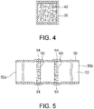
FIG. 3 is a cross-sectional view showing another example of the configuration of the heat exchanger according to the embodiment of the present invention. -
FIG. 4 is a cross-sectional view of the heat exchanger shown inFIG. 3 , taken along a line B-B. -
FIG. 5 is a cross-sectional view showing still another example of the configuration of the heat exchanger according to the embodiment of the present invention. -
FIG. 6 is a cross-sectional view showing still another example of the configuration of the heat exchanger according to the embodiment of the present invention. -
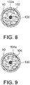
FIG. 7 is a cross-sectional view showing still another example of the configuration of the heat exchanger according to the embodiment of the present invention. -
FIG. 8 is a cross-sectional view of the heat exchanger shown inFIG. 7 , taken along a line C-C. -
FIG. 9 is a cross-sectional view of the heat exchanger shown inFIG. 7 , taken along a line D-D. - Hereinafter, an embodiment of the present invention will be described with reference to the drawings.
FIG. 1 to FIG. 9 are cross-sectional views showing various examples of a heat exchanger according to the present embodiment. The heat exchanger according to the present embodiment causes a fluid as a heat transfer medium to flow in a pipe, thereby heating the fluid or dissipating heat from the fluid. - First, the heat exchanger shown in
FIG. 1 and FIG. 2 will be described. The heat exchanger shown inFIG. 1 and FIG. 2 includes apipe 10 having a cylindrical shape and having a circular cross-section, and ametal fiber structure 20 having a substantially columnar shape and disposed inside thepipe 10. A fluid (specifically, liquid or gas) as a heat transfer medium flows through aflow passage 12 formed inside thepipe 10. More specifically, aninlet 10a and anoutlet 10b for the fluid are formed at both ends of thepipe 10, respectively, and the fluid entering the inside of thepipe 10 through theinlet 10a passes through theflow passage 12 and is discharged from theoutlet 10b. - The
pipe 10 serves as a housing body in which themetal fiber structure 20 is housed. Thepipe 10 is made of, for example, a metal selected from the group consisting of stainless steel, iron, copper, aluminum, bronze, brass, nickel, chromium, and the like. - The
metal fiber structure 20 is formed from metal fibers. Metal-coated fibers may be used as such metal fibers. In addition, themetal fiber structure 20 may be a metal fiber structure into which a nonwoven fabric, a woven fabric, a mesh, or the like formed by using a wet or dry process is processed. Preferably, a metal fiber nonwoven fabric in which metal fibers are bonded together is used as themetal fiber structure 20. The metal fibers being bonded together means that the metal fibers are physically fixed to each other to form bonded portions. In themetal fiber structure 20, the metal fibers may be directly fixed to each other at bonded portions, or parts of the metal fibers may be indirectly fixed to each other via a component other than the metal component. - Since the
metal fiber structure 20 is formed from metal fibers, voids exist inside themetal fiber structure 20. Accordingly, the fluid flowing through theflow passage 12 in thepipe 10 can pass through the inside of themetal fiber structure 20. In addition, in the case where the metal fibers are bonded together in themetal fiber structure 20, voids are more easily formed between the metal fibers forming themetal fiber structure 20. Such voids may be formed, for example, by entangling the metal fibers. Since themetal fiber structure 20 has such voids, the fluid flowing through theflow passage 12 of thepipe 10 is introduced into the inside of themetal fiber structure 20, so that the heat exchange performance for the fluid is easily enhanced. In addition, in themetal fiber structure 20, the metal fibers are preferably sintered at the bonded portions. When the metal fibers are sintered, the thermal conduction properties and the homogeneity of themetal fiber structure 20 are easily stabilized. - A specific example of the metal forming the metal fibers included in the
metal fiber structure 20 is not limited, and may be selected from the group consisting of stainless steel, iron, copper, aluminum, bronze, brass, nickel, chromium, and the like, or may be a noble metal selected from the group consisting of gold, platinum, silver, palladium, rhodium, iridium, ruthenium, osmium, and the like. Among them, copper fibers and aluminum fibers are preferable since these fibers have excellent thermal conduction properties and moderate balance between rigidity and plastic deformability. - The material of the metal fibers forming the
metal fiber structure 20 and the material of thepipe 10 are preferably different from each other. Specifically, whereas the metal fibers forming themetal fiber structure 20 may be copper fibers, the material of thepipe 10 may be aluminum. - As shown in
FIG. 1 and FIG. 2 , a gap is formed at least partially between themetal fiber structure 20 housed in thepipe 10 and the inner surface of thepipe 10. That is, themetal fiber structure 20 exists inside thepipe 10 in a state where themetal fiber structure 20 is not bonded to the inner surface of thepipe 10. Therefore, themetal fiber structure 20 is freely movable inside thepipe 10 along the flowing direction of the fluid. In the present embodiment, the fluid flowing through theflow passage 12 in thepipe 10 can pass through the gap formed between themetal fiber structure 20 and the inner surface of thepipe 10. In addition, even when themetal fiber structure 20 moves inside thepipe 10, since themetal fiber structure 20 is made of metal fibers and has cushioning properties, the inner surface of thepipe 10 can be inhibited from being damaged by themetal fiber structure 20. In particular, the hardness of the material of thepipe 10 is preferably larger than the hardness of the material of themetal fiber structure 20. In this case, even when themetal fiber structure 20 moves inside thepipe 10, the inner surface of thepipe 10 can be further inhibited from being damaged by themetal fiber structure 20. - The size of the gap between the
metal fiber structure 20 housed in thepipe 10 and the inner surface of thepipe 10 is in the range of 10 µm to 500 µm, preferably in the range of 30 µm to 300 µm, and further preferably in the range of 50 µm to 200 µm. The size of the gap between themetal fiber structure 20 housed in thepipe 10 and the inner surface of thepipe 10 refers to the distance between thepipe 10 and themetal fiber structure 20 in a direction orthogonal to the inner surface of thepipe 10. When the size of the gap is set to be not less than 10 µm, an increase in pressure loss can be prevented, so that it can be prevented from being difficult for the fluid to pass through the gap. On the other hand, when the size of the gap is set to be not greater than 500 µm, the fluid can be prevented from flowing through the gap without resistance, so that the heat exchange performance can be enhanced. - In the heat exchanger of the present embodiment configured as described above, the gap is formed at least partially between the
metal fiber structure 20 housed in thepipe 10 as a housing body and the inner surface of thepipe 10. Therefore, the surface area of themetal fiber structure 20 with which the fluid flowing through thepipe 10 comes into contact is increased, so that the thermal conductivity of themetal fiber structure 20 can be increased. In the case where themetal fiber structure 20 is made of randomly arranged short metal fibers, it is easy to generate turbulent flow in the fluid flowing through thepipe 10. In this case, the staying time of the fluid flowing through thepipe 10 can be lengthened, so that the heat transfer effect can be enhanced. In addition, the temperature of the fluid flowing through thepipe 10 can be made uniform (for example, the temperatures at a center portion of thepipe 10 and near the inner wall of thepipe 10 can be made uniform). In the case where a gap is formed at least partially between themetal fiber structure 20 and the inner surface of thepipe 10 as described above, the thermal conductivity of themetal fiber structure 20 can be increased, and the staying time of the fluid flowing through thepipe 10 can be lengthened, thereby enhancing the heat transfer effect, so that the thermal conduction properties for the fluid can be enhanced. In the case where themetal fiber structure 20 is completely separated from thepipe 10, even when such a configuration is applied to a heat exchanger that repeatedly performs rapid heating and rapid cooling, themetal fiber structure 20 does not follow expansion and contraction of thepipe 10, so that themetal fiber structure 20 can be inhibited from being damaged. In addition, in the case where a gap is formed at least partially between themetal fiber structure 20 and the inner surface of thepipe 10, it is easy to release the internal pressure due to the fluid flowing through thepipe 10. - In the case where a metal structure is simply housed inside the
pipe 10, if a gap is formed between the metal structure and the inner surface of thepipe 10, the inner surface of thepipe 10 may be damaged by the metal structure when the metal structure moves inside thepipe 10. On the other hand, as described above, since themetal fiber structure 20 is made of metal fibers and has cushioning properties, the inner surface of thepipe 10 can be inhibited from being damaged by themetal fiber structure 20. - Moreover, in the heat exchanger shown in
FIG. 1 and FIG. 2 , themetal fiber structure 20 is freely movable inside thepipe 10. Therefore, it is easier to generate turbulent flow when the fluid flows through theflow passage 12 of thepipe 10. Accordingly, the staying time of the fluid flowing through thepipe 10 is further lengthened, so that the heat transfer effect can be further enhanced. - Moreover, in the heat exchanger shown in
FIG. 1 and FIG. 2 , in order to make it easier to generate turbulent flow when the fluid flows through theflow passage 12 of thepipe 10, a blade (not shown) may be attached to an end portion of themetal fiber structure 20. In the case where such a blade is attached, the fluid flowing through theflow passage 12 of thepipe 10 comes into contact with the blade of themetal fiber structure 20, thereby rotating themetal fiber structure 20 inside thepipe 10. Accordingly, it is easier to generate turbulent flow when the fluid flows through theflow passage 12 of thepipe 10. - Moreover, in the heat exchanger shown in
FIG. 1 and FIG. 2 , only a part of the outer circumferential surface of themetal fiber structure 20 may be attached to the inner surface of thepipe 10 instead of themetal fiber structure 20 being completely separated from the inner surface of thepipe 10. In this case as well, when a gap is formed between the inner surface of thepipe 10 and a portion, of themetal fiber structure 20, which is not attached to the inner surface of thepipe 10, the thermal conductivity of themetal fiber structure 20 can be increased, and the staying time of the fluid flowing through thepipe 10 can be lengthened, thereby enhancing the heat transfer effect, so that the thermal conduction properties for the fluid can be enhanced. - The heat exchanger according to the present embodiment is not limited to the one shown in
FIG. 1 and FIG. 2 . Another example of the heat exchanger according to the present embodiment will be described with reference toFIG. 3 andFIG. 4 . - The heat exchanger shown in
FIG. 3 andFIG. 4 includes apipe 30 having a substantially square cross-section, and a plurality of (three in the example shown inFIG. 3 andFIG. 4 )metal fiber structures 40 each having a substantially rectangular parallelepiped shape (specifically, for example, a plate shape) and disposed inside thepipe 30. A fluid (specifically, liquid or gas) as a heat transfer medium flows through aflow passage 32 formed inside thepipe 30. More specifically, aninlet 30a and anoutlet 30b for the fluid are formed at both ends of thepipe 30, respectively, and the fluid entering the inside of thepipe 30 through theinlet 30a passes through theflow passage 32 and is discharged from theoutlet 30b. Thepipe 30 serves as a housing body in which eachmetal fiber structure 40 is housed. As the metal forming thepipe 30, the same type as the metal forming thepipe 10 shown inFIG. 1 and FIG. 2 is used. In addition, as the metal fibers forming eachmetal fiber structure 40, the same type as the metal fibers forming themetal fiber structure 20 shown inFIG. 1 and FIG. 2 is used. Since eachmetal fiber structure 40 is formed from metal fibers as described above, voids exist inside eachmetal fiber structure 40. Accordingly, the fluid flowing through theflow passage 32 in thepipe 30 can pass through the inside of eachmetal fiber structure 40. - In the heat exchanger shown in
FIG. 3 andFIG. 4 , retainingmembers 34 are provided in order to retain eachmetal fiber structure 40 at a predetermined position. Such retainingmembers 34 are, for example, projections formed on the inner surface of thepipe 30. Sincesuch retaining members 34 are provided, eachmetal fiber structure 40 does not move to a large extent inside thepipe 30 along the flowing direction of the fluid as compared to the heat exchanger shown inFIG. 1 and FIG. 2 . - Moreover, as shown in
FIG. 3 andFIG. 4 , a gap is formed at least partially between eachmetal fiber structure 40 housed in thepipe 30 and the inner surface of thepipe 30. That is, eachmetal fiber structure 40 exists inside thepipe 30 in a state where themetal fiber structure 40 is not bonded to the inner surface of thepipe 30. Accordingly, the fluid flowing through theflow passage 32 in thepipe 30 can pass through the gap formed between eachmetal fiber structure 40 and the inner surface of thepipe 30. In addition, although eachmetal fiber structure 40 is retained at a predetermined position inside thepipe 30 by the retainingmembers 34, since the gap is formed at least partially between eachmetal fiber structure 40 and the inner surface of thepipe 30, eachmetal fiber structure 40 may move slightly. However, since eachmetal fiber structure 40 is made of metal fibers and has cushioning properties, the inner surface of thepipe 30 can be inhibited from being damaged by eachmetal fiber structure 40. - The size of the gap between each
metal fiber structure 40 housed in thepipe 30 and the inner surface of thepipe 30 is in the range of 10 µm to 500 µm, preferably in the range of 30 µm to 300 µm, and further preferably in the range of 50 µm to 200 µm. The size of the gap between eachmetal fiber structure 40 housed in thepipe 30 and the inner surface of thepipe 30 refers to the distance between thepipe 30 and eachmetal fiber structure 40 in a direction orthogonal to the inner surface of thepipe 30. When the size of the gap is set to be not less than 10 µm, an increase in pressure loss can be prevented, so that it can be prevented from being difficult for the fluid to pass through the gap. On the other hand, when the size of the gap is set to be not greater than 500 µm, the fluid can be prevented from flowing through the gap without resistance, so that the heat exchange performance can be enhanced. - In the heat exchanger of the present embodiment shown in
FIG. 3 andFIG. 4 as well, similar to the heat exchanger shown inFIG. 1 and FIG. 2 , the gap is formed at least partially between eachmetal fiber structure 40 housed in thepipe 30 as a housing body and the inner surface of thepipe 30. Therefore, the surface area of eachmetal fiber structure 40 with which the fluid flowing through thepipe 30 comes into contact is increased, so that the thermal conductivity of eachmetal fiber structure 40 can be increased. In addition, the temperature of the fluid flowing through thepipe 30 can be made uniform. Moreover, in the case where a gap is formed at least partially between eachmetal fiber structure 40 and the inner surface of thepipe 30, it is easy to generate turbulent flow in the fluid flowing through thepipe 30. In this case, the staying time of the fluid flowing through thepipe 30 is lengthened, so that the heat transfer effect can be enhanced. In the case where a gap is formed at least partially between eachmetal fiber structure 40 and the inner surface of thepipe 30 as described above, the thermal conductivity of eachmetal fiber structure 40 can be increased, and the staying time of the fluid flowing through thepipe 30 can be lengthened, thereby enhancing the heat transfer effect, so that the thermal conduction properties for the fluid can be enhanced. - Next, still another example of the heat exchanger according to the present embodiment will be described with reference to
FIG. 5 . - The heat exchanger shown in
FIG. 5 includes apipe 50 having a substantially square cross-section, and a plurality of (two inFIG. 5 )metal fiber structures 60 each having a substantially rectangular parallelepiped shape (specifically, for example, a plate shape) and disposed inside thepipe 50. A fluid (specifically, liquid or gas) as a heat transfer medium flows through aflow passage 52 formed inside thepipe 50. More specifically, aninlet 50a and anoutlet 50b for the fluid are formed at both ends of thepipe 50, respectively, and the fluid entering the inside of thepipe 50 through theinlet 50a passes through theflow passage 52 and is discharged from theoutlet 50b. Thepipe 50 serves as a housing body in which eachmetal fiber structure 60 is housed. As the metal forming thepipe 50, the same type as the metal forming thepipe 10 shown inFIG. 1 and FIG. 2 is used. In addition, as the metal fibers forming eachmetal fiber structure 60, the same type as the metal fibers forming themetal fiber structure 20 shown inFIG. 1 and FIG. 2 is used. Since eachmetal fiber structure 60 is formed from metal fibers as described above, voids exist inside eachmetal fiber structure 60. Accordingly, the fluid flowing through theflow passage 52 in thepipe 50 can pass through the inside of eachmetal fiber structure 60. - In the heat exchanger shown in
FIG. 5 , in order to retain the respectivemetal fiber structures 60 at predetermined positions,mountain portions 54 are provided in thepipe 50 such that the cross-sectional areas of parts of thepipe 50 are increased, so that the end edge of eachmetal fiber structure 60 is held by themountain portion 54. More specifically, the cross-section of each portion other than themountain portions 54 in thepipe 50 is smaller than the cross-section of eachmetal fiber structure 60. Meanwhile, the cross-section of the portion, of thepipe 50, at which eachmountain portion 54 is provided is larger than the cross-section of eachmetal fiber structure 60. Sincesuch mountain portions 54 are provided in thepipe 50, eachmetal fiber structure 60 does not move to a large extent inside thepipe 50 as compared to the heat exchanger shown inFIG. 1 and FIG. 2 . - Moreover, as shown in
FIG. 5 , a gap is formed at least partially between eachmetal fiber structure 60 housed in thepipe 50 and the inner surface of thepipe 50. That is, eachmetal fiber structure 60 exists inside thepipe 50 in a state where themetal fiber structure 60 is not bonded to the inner surface of thepipe 50. Accordingly, the fluid flowing through theflow passage 52 in thepipe 50 can pass through the gap formed between eachmetal fiber structure 60 and the inner surface of thepipe 50. In addition, although eachmetal fiber structure 60 is retained at a predetermined position inside thepipe 50 by themountain portion 54 of thepipe 50, since the gap is formed at least partially between eachmetal fiber structure 60 and the inner surface of thepipe 50, eachmetal fiber structure 60 may move slightly. However, since eachmetal fiber structure 60 is made of metal fibers and has cushioning properties, the inner surface of thepipe 50 can be inhibited from being damaged by eachmetal fiber structure 60. - The size of the gap between each
metal fiber structure 60 housed in thepipe 50 and the inner surface of thepipe 50 is in the range of 10 µm to 500 µm, preferably in the range of 30 µm to 300 µm, and further preferably in the range of 50 µm to 200 µm. The size of the gap between eachmetal fiber structure 60 housed in thepipe 50 and the inner surface of thepipe 50 refers to the distance between thepipe 50 and eachmetal fiber structure 60 in a direction orthogonal to the inner surface of thepipe 50. When the size of the gap is set to be not less than 10 µm, an increase in pressure loss can be prevented, so that it can be prevented from being difficult for the fluid to pass through the gap. On the other hand, when the size of the gap is set to be not greater than 500 µm, the fluid can be prevented from flowing through the gap without resistance, so that the heat exchange performance can be enhanced. - In the heat exchanger of the present embodiment shown in
FIG. 5 as well, similar to the heat exchanger shown inFIG. 1 and FIG. 2 , the gap is formed at least partially between eachmetal fiber structure 60 housed in thepipe 50 as a housing body and the inner surface of thepipe 50. Therefore, the surface area of eachmetal fiber structure 60 with which the fluid flowing through thepipe 50 comes into contact is increased, so that the thermal conductivity of eachmetal fiber structure 60 can be increased. In addition, the temperature of the fluid flowing through thepipe 50 can be made uniform. Moreover, in the case where a gap is formed at least partially between eachmetal fiber structure 60 and the inner surface of thepipe 50, it is easy to generate turbulent flow in the fluid flowing through thepipe 50. In this case, the staying time of the fluid flowing through thepipe 50 is lengthened, so that the heat transfer effect can be enhanced. In the case where a gap is formed at least partially between eachmetal fiber structure 60 and the inner surface of thepipe 50 as described above, the thermal conductivity of eachmetal fiber structure 60 can be increased, and the staying time of the fluid flowing through thepipe 50 can be lengthened, thereby enhancing the heat transfer effect, so that the thermal conduction properties for the fluid can be enhanced. - Next, still another example of the heat exchanger according to the present embodiment will be described with reference to
FIG. 6 . - The heat exchanger shown in
FIG. 6 includes apipe 70 having a circular cross-section and bent at portions near both ends thereof by about 90°, and ametal fiber structure 80 having a substantially columnar shape and disposed inside thepipe 70. A fluid (specifically, liquid or gas) as a heat transfer medium flows through aflow passage 72 formed inside thepipe 70. More specifically, aninlet 70a and anoutlet 70b for the fluid are formed at both ends of thepipe 70, respectively; and the direction of the fluid entering the inside of thepipe 10 through theinlet 70a is changed at abent portion 74, then the fluid passes through themetal fiber structure 80, the direction of the fluid is subsequently changed at abent portion 76, and the fluid is then discharged from theoutlet 70b. Thepipe 70 serves as a housing body in which themetal fiber structure 80 is housed. As the metal forming thepipe 70, the same type as the metal forming thepipe 10 shown inFIG. 1 and FIG. 2 is used. In addition, as the metal fibers forming themetal fiber structure 80, the same type as the metal fibers forming themetal fiber structure 20 shown inFIG. 1 and FIG. 2 is used. Since themetal fiber structure 80 is formed from metal fibers as described above, voids exist inside themetal fiber structure 80. Accordingly, the fluid flowing through theflow passage 72 in thepipe 70 can pass through the inside of themetal fiber structure 80. - In the heat exchanger shown in
FIG. 6 , themetal fiber structure 80 is retained at a predetermined position by a pair of thebent portions pipe 70. More specifically, since thebent portion 74 is provided in thepipe 70, themetal fiber structure 80 does not move rightward to a large extent from the position shown inFIG. 6 . In addition, since thebent portion 76 is provided in thepipe 70, themetal fiber structure 80 does not move leftward to a large extent from the position shown inFIG. 6 . Since thebent portions pipe 70 as described above, themetal fiber structure 80 does not move to a large extent inside thepipe 70 as compared to the heat exchanger shown inFIG. 1 and FIG. 2 . - Moreover, as shown in
FIG. 6 , a gap is formed at least partially between themetal fiber structure 80 housed in thepipe 70 and the inner surface of thepipe 70. That is, themetal fiber structure 80 exists inside thepipe 70 in a state where themetal fiber structure 80 is not bonded to the inner surface of thepipe 70. Accordingly, the fluid flowing through theflow passage 72 in thepipe 70 can pass through the gap formed between themetal fiber structure 80 and the inner surface of thepipe 70. In addition, although themetal fiber structure 80 is retained at a predetermined position inside thepipe 70 by the respectivebent portions pipe 70, since the gap is formed at least partially between themetal fiber structure 80 and the inner surface of thepipe 70, themetal fiber structure 80 may move slightly. However, since themetal fiber structure 80 is made of metal fibers and has cushioning properties, the inner surface of thepipe 70 can be inhibited from being damaged by themetal fiber structure 80. - The size of the gap between the
metal fiber structure 80 housed in thepipe 70 and the inner surface of thepipe 70 is in the range of 10 µm to 500 µm, preferably in the range of 30 µm to 300 µm, and further preferably in the range of 50 µm to 200 µm. The size of the gap between themetal fiber structure 80 housed in thepipe 70 and the inner surface of thepipe 70 refers to the distance between thepipe 70 and themetal fiber structure 80 in a direction orthogonal to the inner surface of thepipe 70. When the size of the gap is set to be not less than 10 µm, an increase in pressure loss can be prevented, so that it can be prevented from being difficult for the fluid to pass through the gap. On the other hand, when the size of the gap is set to be not greater than 500 µm, the fluid can be prevented from flowing through the gap without resistance, so that the heat exchange performance can be enhanced. - In the heat exchanger of the present embodiment shown in
FIG. 6 as well, similar to the heat exchanger shown inFIG. 1 and FIG. 2 , the gap is formed at least partially between themetal fiber structure 80 housed in thepipe 70 as a housing body and the inner surface of thepipe 70. Therefore, the surface area of themetal fiber structure 80 with which the fluid flowing through thepipe 70 comes into contact is increased, so that the thermal conductivity of themetal fiber structure 80 can be increased. In addition, the temperature of the fluid flowing through thepipe 70 can be made uniform. Moreover, in the case where a gap is formed at least partially between themetal fiber structure 80 and the inner surface of thepipe 70, it is easy to generate turbulent flow in the fluid flowing through thepipe 70. In this case, the staying time of the fluid flowing through thepipe 70 is lengthened, so that the heat transfer effect can be enhanced. In the case where a gap is formed at least partially between themetal fiber structure 80 and the inner surface of thepipe 70 as described above, the thermal conductivity of themetal fiber structure 80 can be increased, and the staying time of the fluid flowing through thepipe 70 can be lengthened, thereby enhancing the heat transfer effect, so that the thermal conduction properties for the fluid can be enhanced. - Next, still another example of the heat exchanger according to the present embodiment will be described with reference to
FIG. 7 to FIG. 9 . - The heat exchanger shown in
FIG. 7 to FIG. 9 includes apipe 90 having a cylindrical shape and having a circular cross-section, a plurality of (five in the example shown inFIG. 7 , etc.)metal fiber structures pipe 90, and a rod-shapedconnection member 100 connecting the respectivemetal fiber structures flow passage 92 formed inside thepipe 90. More specifically, aninlet 90a and anoutlet 90b for the fluid are formed at both ends of thepipe 90, respectively, and the fluid entering the inside of thepipe 90 through theinlet 90a passes through theflow passage 92 and is discharged from theoutlet 90b. Thepipe 90 serves as a housing body in which the respectivemetal fiber structures pipe 90, the same type as the metal forming thepipe 10 shown inFIG. 1 and FIG. 2 is used. - The rod-shaped
connection member 100 extends through through holes (not shown) formed at the centers of the respectivemetal fiber structures metal fiber structures connection member 100. Specifically, theconnection member 100 is made of, for example, a metal selected from the group consisting of stainless steel, iron, copper, aluminum, bronze, brass, nickel, chromium, and the like. The respectivemetal fiber structures connection member 100. In addition, as shown inFIG. 8 and FIG. 9 , a plurality of (for example, eight) throughholes metal fiber structures flow passage 92 of thepipe 90 can pass through each of the throughholes holes metal fiber structures connection member 100 are different from each other. Furthermore, as shown inFIG. 7 , thesemetal fiber structures holes metal fiber structures metal fiber structures metal fiber structure 20 shown inFIG. 1 and FIG. 2 is used. Since each of themetal fiber structures metal fiber structures flow passage 92 in thepipe 90 can pass through the inside of each of themetal fiber structures holes - As shown in
FIG. 7 to FIG. 9 , a gap is formed at least partially between each of themetal fiber structures pipe 90 and the inner surface of thepipe 90. That is, each of themetal fiber structures pipe 90 in a state where themetal fiber structure pipe 90. Therefore, an assembly of the respectivemetal fiber structures connection member 100 is freely movable inside thepipe 90. Accordingly, the fluid flowing through theflow passage 92 in thepipe 90 can pass through the gap formed between each of themetal fiber structures pipe 90. In addition, even when the assembly of the respectivemetal fiber structures connection member 100 moves inside thepipe 90, since each of themetal fiber structures pipe 90 can be inhibited from being damaged by the respectivemetal fiber structures - The size of the gap between each of the
metal fiber structures pipe 90 and the inner surface of thepipe 90 is in the range of 10 µm to 500 µm, preferably in the range of 30 µm to 300 µm, and further preferably in the range of 50 µm to 200 µm. The size of the gap between each of themetal fiber structures pipe 90 and the inner surface of thepipe 90 refers to the distance between thepipe 90 and each of themetal fiber structures pipe 90. When the size of the gap is set to be not less than 10 µm, an increase in pressure loss can be prevented, so that it can be prevented from being difficult for the fluid to pass through the gap. On the other hand, when the size of the gap is set to be not greater than 500 µm, the fluid can be prevented from flowing through the gap without resistance, so that the heat exchange performance can be enhanced. - In the heat exchanger of the present embodiment shown in
FIG. 7 to FIG. 9 as well, similar to the heat exchanger shown inFIG. 1 and FIG. 2 , the gap is formed at least partially between each of themetal fiber structures pipe 90 as a housing body and the inner surface of thepipe 90. Therefore, the surface area of each of themetal fiber structures pipe 90 comes into contact is increased, so that the thermal conductivity of each of themetal fiber structures pipe 90 can be made uniform. Moreover, in the case where a gap is formed at least partially between each of themetal fiber structures pipe 90, it is easy to generate turbulent flow in the fluid flowing through thepipe 90. In this case, the staying time of the fluid flowing through thepipe 90 is lengthened, so that the heat transfer effect can be enhanced. In the case where a gap is formed at least partially between each of themetal fiber structures pipe 90 as described above, the thermal conductivity of each of themetal fiber structures pipe 90 can be lengthened, thereby enhancing the heat transfer effect, so that the thermal conduction properties for the fluid can be enhanced. - Moreover, in the heat exchanger shown in
FIG. 7 to FIG. 9 , the assembly of the respectivemetal fiber structures connection member 100 is freely movable inside thepipe 90. Therefore, it is easier to generate turbulent flow when the fluid flows through theflow passage 92 of thepipe 90. Accordingly, the staying time of the fluid flowing through thepipe 90 is further lengthened, so that the heat transfer effect can be further enhanced. - Moreover, in the heat exchanger shown in
FIG. 7 to FIG. 9 , the rod-shapedconnection member 100 may be rotated by a drive means which is not shown. Accordingly, the respectivemetal fiber structures connection member 100, so that it is easier to generate turbulent flow in the fluid flowing through theflow passage 92 of thepipe 90. In addition, in the case where the fluid flowing through theflow passage 92 of thepipe 90 is a polymer liquid, the polymer liquid can be diffused by rotating the respectivemetal fiber structures - Moreover, in the heat exchanger shown in
FIG. 7 to FIG. 9 , instead of the respectivemetal fiber structures connection member 100, the respectivemetal fiber structures connection member 100 such that each of themetal fiber structures connection member 100 in the right-left direction inFIG. 7 . In addition, in this case, theconnection member 100 may be provided so as to be fixed in position inside thepipe 90. In such a case as well, since each of themetal fiber structures connection member 100, it is easier to generate turbulent flow in the fluid flowing through theflow passage 92 of thepipe 90.
Claims (15)
- A heat exchanger comprising:a metal fiber structure formed from metal fibers; anda housing body in which the metal fiber structure is housed, whereina gap is formed at least partially between the metal fiber structure housed in the housing body and an inner surface of the housing body.
- The heat exchanger according to claim 1, wherein an inlet and an outlet for a fluid are formed at both ends of the housing body, respectively, such that the fluid entering an inside of the housing body through the inlet passes through an inside of the metal fiber structure or the gap formed between the metal fiber structure and the inner surface of the housing body and is discharged from the outlet.
- The heat exchanger according to claim 2, wherein the housing body has a cylindrical shape.
- The heat exchanger according to any one of claims 1 to 3, wherein the metal fiber structure is freely movable inside the housing body.
- The heat exchanger according to claim 4, wherein the metal fiber structure is freely movable along a flowing direction of the fluid flowing inside the housing body.
- The heat exchanger according to any one of claims 1 to 3, wherein a retaining member for retaining the metal fiber structure at a predetermined position is provided in the housing body such that movement of the metal fiber structure along a flowing direction of the fluid flowing inside the housing body is restricted by the retaining member.
- The heat exchanger according to any one of claims 1 to 6, wherein a material of the metal fibers forming the metal fiber structure and a material of the housing body are different from each other.
- The heat exchanger according to any one of claims 1 to 7, wherein a through hole is formed in the metal fiber structure.
- The heat exchanger according to claim 8, wherein the through hole extends along the flowing direction of the fluid flowing inside the housing body.
- The heat exchanger according to any one of claims 1 to 9, wherein the metal fibers forming the metal fiber structure are bonded to each other.
- The heat exchanger according to any one of claims 1 to 10, wherein a blade is attached to an end portion of the metal fiber structure such that the fluid flowing inside the housing body comes into contact with the blade, thereby rotating the metal fiber structure inside the housing body.
- The heat exchanger according to claim 6, wherein the retaining member includes a projection formed on the inner surface of the housing body.
- The heat exchanger according to claim 6, wherein the retaining member includes a mountain portion at which a cross-sectional area of a part of the housing body is increased, a cross-section of a portion other than the mountain portion in the housing body is smaller than a cross-section of the metal fiber structure, and a cross-section of a portion, of the housing body, at which the mountain portion is provided is larger than the cross-section of the metal fiber structure.
- The heat exchanger according to any one of claims 1 to 13, wherein the housing body includes a pipe having bent portions formed at portions near both ends thereof, and the metal fiber structure is disposed between the bent portions inside the housing body.
- The heat exchanger according to any one of claims 1 to 14, wherein the metal fibers include copper fibers or aluminum fibers.
Applications Claiming Priority (2)
| Application Number | Priority Date | Filing Date | Title |
|---|---|---|---|
| JP2020026159 | 2020-02-19 | ||
| PCT/JP2021/004407 WO2021166697A1 (en) | 2020-02-19 | 2021-02-05 | Heat exchanger |
Publications (2)
| Publication Number | Publication Date |
|---|---|
| EP4110010A1 true EP4110010A1 (en) | 2022-12-28 |
| EP4110010A4 EP4110010A4 (en) | 2023-08-09 |
Family
ID=77391022
Family Applications (1)
| Application Number | Title | Priority Date | Filing Date |
|---|---|---|---|
| EP21756195.0A Pending EP4110010A4 (en) | 2020-02-19 | 2021-02-05 | Heat exchanger |
Country Status (7)
| Country | Link |
|---|---|
| US (1) | US12568558B2 (en) |
| EP (1) | EP4110010A4 (en) |
| JP (2) | JP7386963B2 (en) |
| KR (1) | KR102771228B1 (en) |
| CN (1) | CN115152323B (en) |
| TW (1) | TWI775316B (en) |
| WO (1) | WO2021166697A1 (en) |
Family Cites Families (39)
| Publication number | Priority date | Publication date | Assignee | Title |
|---|---|---|---|---|
| US3289756A (en) * | 1964-10-15 | 1966-12-06 | Olin Mathieson | Heat exchanger |
| US3704748A (en) * | 1970-02-11 | 1972-12-05 | Ratheon Co | Heat transfer structure |
| US4108241A (en) * | 1975-03-19 | 1978-08-22 | The United States Of America As Represented By The Administrator Of The National Aeronautics And Space Administration | Heat exchanger and method of making |
| GB1562905A (en) * | 1976-08-17 | 1980-03-19 | Othmer D | Electric resistance heating utilising the skin effect in magnetic metal shapes |
| JPS612243Y2 (en) * | 1981-02-16 | 1986-01-24 | ||
| JPS59150950A (en) * | 1983-02-15 | 1984-08-29 | Asahi Glass Co Ltd | Heat exchanger tube used in hot gas machine |
| JPS602240U (en) | 1983-06-17 | 1985-01-09 | 三菱電機株式会社 | fluid heating device |
| CA2107464C (en) * | 1991-04-15 | 2003-12-09 | Terry R. Galloway | Very high temperature heat exchanger |
| US5405586A (en) * | 1993-07-01 | 1995-04-11 | Uop | Radial flow heat exchanging reactor |
| WO1996013138A1 (en) * | 1994-10-24 | 1996-05-02 | Matsushita Electric Industrial Co., Ltd. | Steam generating apparatus of induction heating system |
| JPH09283268A (en) | 1996-04-17 | 1997-10-31 | Mamoru Fukumura | Fluid heating method |
| JP3043911U (en) | 1997-05-30 | 1997-12-12 | 佑仲實業股▲ふん▼有限公司 | V-shaped grooved fiber capillary device for low-heat conduit |
| JPH11132685A (en) * | 1997-10-24 | 1999-05-21 | Mikawa Gijutsu Kogyo Kk | Heat exchanging body |
| US6459854B1 (en) | 2000-01-24 | 2002-10-01 | Nestec S.A. | Process and module for heating liquid |
| JP2003083694A (en) | 2001-09-11 | 2003-03-19 | Mikawa Gijutsu Kogyo Kk | Heat exchanger body |
| JP2003123949A (en) | 2001-10-15 | 2003-04-25 | Kogi Corp | Electromagnetic induction heating device |
| JP2004279021A (en) * | 2003-02-27 | 2004-10-07 | Usui Kokusai Sangyo Kaisha Ltd | Heat transfer pipe with internally mounted resin fin member |
| JP2006170571A (en) * | 2004-12-17 | 2006-06-29 | Hitachi Cable Ltd | Double tube heat exchanger |
| JP5559088B2 (en) * | 2010-05-18 | 2014-07-23 | 株式会社ワイ・ジェー・エス. | Heat exchanger |
| EP2508374B1 (en) * | 2011-04-07 | 2013-10-30 | Kabushiki-Kaisha Takumi | Heating unit of vehicle heating system |
| KR20120135776A (en) * | 2011-06-07 | 2012-12-17 | 디에스엠 주식회사 | Heat exchange pipe |
| MX346864B (en) * | 2012-01-03 | 2017-04-04 | Philip Morris Products Sa | An aerosol generating device and system with improved airflow. |
| US9599404B2 (en) | 2013-08-27 | 2017-03-21 | Black Night Enterprises, Inc. | Fluid direct contact heat exchange apparatus and method |
| ES2703350T5 (en) * | 2014-05-12 | 2024-07-10 | Philip Morris Products Sa | Improved vaporizer device |
| JP2015224804A (en) | 2014-05-26 | 2015-12-14 | 株式会社ノーリツ | Heat exchanger |
| JP2016020757A (en) * | 2014-07-14 | 2016-02-04 | 日立アプライアンス株式会社 | Manufacturing method for refrigeration cycle device and cross fin tube type heat exchanger used for the same |
| GB201511358D0 (en) * | 2015-06-29 | 2015-08-12 | Nicoventures Holdings Ltd | Electronic aerosol provision systems |
| US10237926B2 (en) * | 2015-11-09 | 2019-03-19 | Pace, Inc. | Inductive heater for area array rework system and soldering handpieces |
| FR3048494B1 (en) * | 2016-03-04 | 2018-03-02 | Commissariat A L'energie Atomique Et Aux Energies Alternatives | ENERGY STORAGE DEVICE BY PHASE CHANGE MATERIAL INCLUDING AN INTEGRATED ELECTRICAL CHARGE IN THE CIRCUIT OF THE HEAT TRANSFER FLUID |
| RU2728255C2 (en) * | 2016-04-27 | 2020-07-28 | Филип Моррис Продактс С.А. | Aerosol-generating device with fixing means |
| JP3208098U (en) | 2016-10-11 | 2016-12-22 | 株式会社バルビス | Porous heat exchanger |
| JP6906930B2 (en) | 2016-11-24 | 2021-07-21 | 株式会社ブリヂストン | Electromagnetic induction heating device |
| US11019850B2 (en) * | 2018-02-26 | 2021-06-01 | Rai Strategic Holdings, Inc. | Heat conducting substrate for electrically heated aerosol delivery device |
| JP7018797B2 (en) | 2018-03-27 | 2022-02-14 | 株式会社巴川製紙所 | Protective material and protective material in a bag |
| EP3829354B1 (en) * | 2018-08-01 | 2025-02-19 | Fontem Ventures B.V. | Heat-not-burn smoking article |
| JP2021143366A (en) * | 2020-03-11 | 2021-09-24 | 三菱マテリアル株式会社 | Heat exchange pipe and its manufacturing method |
| KR102451070B1 (en) * | 2020-06-03 | 2022-10-05 | 주식회사 케이티앤지 | Apparatus for generating aerosol based on external heating |
| EP3932231B1 (en) * | 2020-09-28 | 2023-09-06 | China Tobacco Yunnan Industrial Co., Ltd | Smoking apparatus for induction heating at front end of cigarette |
| CN119063461A (en) * | 2023-06-02 | 2024-12-03 | 中国石化工程建设有限公司 | An electric heating process heating furnace |
-
2021
- 2021-02-05 CN CN202180015859.8A patent/CN115152323B/en active Active
- 2021-02-05 JP JP2022501801A patent/JP7386963B2/en active Active
- 2021-02-05 WO PCT/JP2021/004407 patent/WO2021166697A1/en not_active Ceased
- 2021-02-05 US US17/800,939 patent/US12568558B2/en active Active
- 2021-02-05 KR KR1020227030506A patent/KR102771228B1/en active Active
- 2021-02-05 EP EP21756195.0A patent/EP4110010A4/en active Pending
- 2021-02-18 TW TW110105523A patent/TWI775316B/en active
-
2023
- 2023-10-17 JP JP2023178739A patent/JP7681660B2/en active Active
Also Published As
| Publication number | Publication date |
|---|---|
| JP7386963B2 (en) | 2023-11-27 |
| JPWO2021166697A1 (en) | 2021-08-26 |
| EP4110010A4 (en) | 2023-08-09 |
| KR102771228B1 (en) | 2025-02-20 |
| CN115152323B (en) | 2024-10-15 |
| CN115152323A (en) | 2022-10-04 |
| TW202138735A (en) | 2021-10-16 |
| KR20220136412A (en) | 2022-10-07 |
| JP2023179718A (en) | 2023-12-19 |
| US20230080550A1 (en) | 2023-03-16 |
| WO2021166697A1 (en) | 2021-08-26 |
| US12568558B2 (en) | 2026-03-03 |
| JP7681660B2 (en) | 2025-05-22 |
| TWI775316B (en) | 2022-08-21 |
Similar Documents
| Publication | Publication Date | Title |
|---|---|---|
| JP4460856B2 (en) | Microstructure cooler and its use | |
| US5628363A (en) | Composite continuous sheet fin heat exchanger | |
| EP2208874B1 (en) | Heat recovery system | |
| JP4907703B2 (en) | Microchannel heat exchanger, method of cooling the heat source | |
| US7686071B2 (en) | Blade-thru condenser having reeds and heat dissipation system thereof | |
| JP2006515054A5 (en) | ||
| US10107576B2 (en) | Heat exchanger | |
| JP5135225B2 (en) | Use of a micro heat transfer device as a fluid cooler for micro heat transfer and electronic devices | |
| KR20230006539A (en) | temperature control unit | |
| JP2011103384A (en) | Heat sink | |
| US12568558B2 (en) | Heat exchanger | |
| JP3632402B2 (en) | Heat pump water heater | |
| US20230194193A1 (en) | Temperature regulation unit | |
| WO2011096801A2 (en) | Heat exchanger | |
| US12550291B2 (en) | Temperature regulation unit and method for manufacturing temperature regulation unit | |
| TWI846369B (en) | Heat diffusion device and electronic device | |
| JP2016130625A (en) | Heat exchanger and sheet metal plate for heat exchanger | |
| JP3918843B2 (en) | Heat pump water heater | |
| JP6429122B2 (en) | Heat exchanger and intermediate plate for heat exchanger | |
| CN118111126A (en) | PTC heater shell water channel structure | |
| JP6525248B2 (en) | Heat exchanger and plate unit for heat exchanger | |
| US20250189239A1 (en) | Three-dimensional vapor chamber device | |
| JP4909725B2 (en) | Heat exchanger | |
| CN118168367A (en) | Thermal Management Integrated Components | |
| WO1998022770A1 (en) | Heat exchanger having a pleated mat of fibers |
Legal Events
| Date | Code | Title | Description |
|---|---|---|---|
| STAA | Information on the status of an ep patent application or granted ep patent |
Free format text: STATUS: THE INTERNATIONAL PUBLICATION HAS BEEN MADE |
|
| PUAI | Public reference made under article 153(3) epc to a published international application that has entered the european phase |
Free format text: ORIGINAL CODE: 0009012 |
|
| STAA | Information on the status of an ep patent application or granted ep patent |
Free format text: STATUS: REQUEST FOR EXAMINATION WAS MADE |
|
| 17P | Request for examination filed |
Effective date: 20220812 |
|
| AK | Designated contracting states |
Kind code of ref document: A1 Designated state(s): AL AT BE BG CH CY CZ DE DK EE ES FI FR GB GR HR HU IE IS IT LI LT LU LV MC MK MT NL NO PL PT RO RS SE SI SK SM TR |
|
| DAV | Request for validation of the european patent (deleted) | ||
| DAX | Request for extension of the european patent (deleted) | ||
| REG | Reference to a national code |
Ref country code: DE Ref legal event code: R079 Free format text: PREVIOUS MAIN CLASS: H05B0003400000 Ipc: H05B0006100000 |
|
| A4 | Supplementary search report drawn up and despatched |
Effective date: 20230706 |
|
| RIC1 | Information provided on ipc code assigned before grant |
Ipc: F28F 13/06 20060101ALI20230630BHEP Ipc: F28F 13/00 20060101ALI20230630BHEP Ipc: F28F 1/40 20060101ALI20230630BHEP Ipc: F28D 1/04 20060101ALI20230630BHEP Ipc: H05B 3/40 20060101ALI20230630BHEP Ipc: H05B 6/10 20060101AFI20230630BHEP |