EP4109683A1 - Cable connection device - Google Patents
Cable connection device Download PDFInfo
- Publication number
- EP4109683A1 EP4109683A1 EP21204201.4A EP21204201A EP4109683A1 EP 4109683 A1 EP4109683 A1 EP 4109683A1 EP 21204201 A EP21204201 A EP 21204201A EP 4109683 A1 EP4109683 A1 EP 4109683A1
- Authority
- EP
- European Patent Office
- Prior art keywords
- connection component
- power cable
- lateral surface
- accommodation space
- cable
- Prior art date
- Legal status (The legal status is an assumption and is not a legal conclusion. Google has not performed a legal analysis and makes no representation as to the accuracy of the status listed.)
- Pending
Links
Images




Classifications
-
- H—ELECTRICITY
- H01—ELECTRIC ELEMENTS
- H01R—ELECTRICALLY-CONDUCTIVE CONNECTIONS; STRUCTURAL ASSOCIATIONS OF A PLURALITY OF MUTUALLY-INSULATED ELECTRICAL CONNECTING ELEMENTS; COUPLING DEVICES; CURRENT COLLECTORS
- H01R9/00—Structural associations of a plurality of mutually-insulated electrical connecting elements, e.g. terminal strips or terminal blocks; Terminals or binding posts mounted upon a base or in a case; Bases therefor
- H01R9/03—Connectors arranged to contact a plurality of the conductors of a multiconductor cable, e.g. tapping connections
- H01R9/031—Connectors arranged to contact a plurality of the conductors of a multiconductor cable, e.g. tapping connections for multiphase cables, e.g. with contact members penetrating insulation of a plurality of conductors
-
- H—ELECTRICITY
- H01—ELECTRIC ELEMENTS
- H01R—ELECTRICALLY-CONDUCTIVE CONNECTIONS; STRUCTURAL ASSOCIATIONS OF A PLURALITY OF MUTUALLY-INSULATED ELECTRICAL CONNECTING ELEMENTS; COUPLING DEVICES; CURRENT COLLECTORS
- H01R9/00—Structural associations of a plurality of mutually-insulated electrical connecting elements, e.g. terminal strips or terminal blocks; Terminals or binding posts mounted upon a base or in a case; Bases therefor
- H01R9/22—Bases, e.g. strip, block, panel
-
- H—ELECTRICITY
- H01—ELECTRIC ELEMENTS
- H01R—ELECTRICALLY-CONDUCTIVE CONNECTIONS; STRUCTURAL ASSOCIATIONS OF A PLURALITY OF MUTUALLY-INSULATED ELECTRICAL CONNECTING ELEMENTS; COUPLING DEVICES; CURRENT COLLECTORS
- H01R12/00—Structural associations of a plurality of mutually-insulated electrical connecting elements, specially adapted for printed circuits, e.g. printed circuit boards [PCB], flat or ribbon cables, or like generally planar structures, e.g. terminal strips, terminal blocks; Coupling devices specially adapted for printed circuits, flat or ribbon cables, or like generally planar structures; Terminals specially adapted for contact with, or insertion into, printed circuits, flat or ribbon cables, or like generally planar structures
- H01R12/50—Fixed connections
- H01R12/51—Fixed connections for rigid printed circuits or like structures
- H01R12/53—Fixed connections for rigid printed circuits or like structures connecting to cables except for flat or ribbon cables
-
- H—ELECTRICITY
- H01—ELECTRIC ELEMENTS
- H01R—ELECTRICALLY-CONDUCTIVE CONNECTIONS; STRUCTURAL ASSOCIATIONS OF A PLURALITY OF MUTUALLY-INSULATED ELECTRICAL CONNECTING ELEMENTS; COUPLING DEVICES; CURRENT COLLECTORS
- H01R12/00—Structural associations of a plurality of mutually-insulated electrical connecting elements, specially adapted for printed circuits, e.g. printed circuit boards [PCB], flat or ribbon cables, or like generally planar structures, e.g. terminal strips, terminal blocks; Coupling devices specially adapted for printed circuits, flat or ribbon cables, or like generally planar structures; Terminals specially adapted for contact with, or insertion into, printed circuits, flat or ribbon cables, or like generally planar structures
- H01R12/70—Coupling devices
- H01R12/71—Coupling devices for rigid printing circuits or like structures
- H01R12/712—Coupling devices for rigid printing circuits or like structures co-operating with the surface of the printed circuit or with a coupling device exclusively provided on the surface of the printed circuit
- H01R12/716—Coupling device provided on the PCB
- H01R12/718—Contact members provided on the PCB without an insulating housing
-
- H—ELECTRICITY
- H01—ELECTRIC ELEMENTS
- H01R—ELECTRICALLY-CONDUCTIVE CONNECTIONS; STRUCTURAL ASSOCIATIONS OF A PLURALITY OF MUTUALLY-INSULATED ELECTRICAL CONNECTING ELEMENTS; COUPLING DEVICES; CURRENT COLLECTORS
- H01R13/00—Details of coupling devices of the kinds covered by groups H01R12/70 or H01R24/00 - H01R33/00
- H01R13/46—Bases; Cases
- H01R13/514—Bases; Cases composed as a modular blocks or assembly, i.e. composed of co-operating parts provided with contact members or holding contact members between them
-
- H—ELECTRICITY
- H01—ELECTRIC ELEMENTS
- H01R—ELECTRICALLY-CONDUCTIVE CONNECTIONS; STRUCTURAL ASSOCIATIONS OF A PLURALITY OF MUTUALLY-INSULATED ELECTRICAL CONNECTING ELEMENTS; COUPLING DEVICES; CURRENT COLLECTORS
- H01R13/00—Details of coupling devices of the kinds covered by groups H01R12/70 or H01R24/00 - H01R33/00
- H01R13/66—Structural association with built-in electrical component
- H01R13/665—Structural association with built-in electrical component with built-in electronic circuit
-
- H—ELECTRICITY
- H01—ELECTRIC ELEMENTS
- H01R—ELECTRICALLY-CONDUCTIVE CONNECTIONS; STRUCTURAL ASSOCIATIONS OF A PLURALITY OF MUTUALLY-INSULATED ELECTRICAL CONNECTING ELEMENTS; COUPLING DEVICES; CURRENT COLLECTORS
- H01R4/00—Electrically-conductive connections between two or more conductive members in direct contact, i.e. touching one another; Means for effecting or maintaining such contact; Electrically-conductive connections having two or more spaced connecting locations for conductors and using contact members penetrating insulation
- H01R4/24—Connections using contact members penetrating or cutting insulation or cable strands
- H01R4/2416—Connections using contact members penetrating or cutting insulation or cable strands the contact members having insulation-cutting edges, e.g. of tuning fork type
- H01R4/242—Connections using contact members penetrating or cutting insulation or cable strands the contact members having insulation-cutting edges, e.g. of tuning fork type the contact members being plates having a single slot
- H01R4/2425—Flat plates, e.g. multi-layered flat plates
- H01R4/2429—Flat plates, e.g. multi-layered flat plates mounted in an insulating base
-
- H—ELECTRICITY
- H01—ELECTRIC ELEMENTS
- H01R—ELECTRICALLY-CONDUCTIVE CONNECTIONS; STRUCTURAL ASSOCIATIONS OF A PLURALITY OF MUTUALLY-INSULATED ELECTRICAL CONNECTING ELEMENTS; COUPLING DEVICES; CURRENT COLLECTORS
- H01R4/00—Electrically-conductive connections between two or more conductive members in direct contact, i.e. touching one another; Means for effecting or maintaining such contact; Electrically-conductive connections having two or more spaced connecting locations for conductors and using contact members penetrating insulation
- H01R4/24—Connections using contact members penetrating or cutting insulation or cable strands
- H01R4/2416—Connections using contact members penetrating or cutting insulation or cable strands the contact members having insulation-cutting edges, e.g. of tuning fork type
- H01R4/242—Connections using contact members penetrating or cutting insulation or cable strands the contact members having insulation-cutting edges, e.g. of tuning fork type the contact members being plates having a single slot
- H01R4/2425—Flat plates, e.g. multi-layered flat plates
- H01R4/2429—Flat plates, e.g. multi-layered flat plates mounted in an insulating base
- H01R4/2433—Flat plates, e.g. multi-layered flat plates mounted in an insulating base one part of the base being movable to push the cable into the slot
-
- H—ELECTRICITY
- H01—ELECTRIC ELEMENTS
- H01R—ELECTRICALLY-CONDUCTIVE CONNECTIONS; STRUCTURAL ASSOCIATIONS OF A PLURALITY OF MUTUALLY-INSULATED ELECTRICAL CONNECTING ELEMENTS; COUPLING DEVICES; CURRENT COLLECTORS
- H01R9/00—Structural associations of a plurality of mutually-insulated electrical connecting elements, e.g. terminal strips or terminal blocks; Terminals or binding posts mounted upon a base or in a case; Bases therefor
- H01R9/22—Bases, e.g. strip, block, panel
- H01R9/223—Insulating enclosures for terminals
-
- H—ELECTRICITY
- H01—ELECTRIC ELEMENTS
- H01R—ELECTRICALLY-CONDUCTIVE CONNECTIONS; STRUCTURAL ASSOCIATIONS OF A PLURALITY OF MUTUALLY-INSULATED ELECTRICAL CONNECTING ELEMENTS; COUPLING DEVICES; CURRENT COLLECTORS
- H01R9/00—Structural associations of a plurality of mutually-insulated electrical connecting elements, e.g. terminal strips or terminal blocks; Terminals or binding posts mounted upon a base or in a case; Bases therefor
- H01R9/22—Bases, e.g. strip, block, panel
- H01R9/24—Terminal blocks
- H01R9/2425—Structural association with built-in components
-
- H—ELECTRICITY
- H02—GENERATION; CONVERSION OR DISTRIBUTION OF ELECTRIC POWER
- H02G—INSTALLATION OF ELECTRIC CABLES OR LINES, OR OF COMBINED OPTICAL AND ELECTRIC CABLES OR LINES
- H02G15/00—Cable fittings
- H02G15/08—Cable junctions
- H02G15/10—Cable junctions protected by boxes, e.g. by distribution, connection or junction boxes
- H02G15/113—Boxes split longitudinally in main cable direction
-
- B—PERFORMING OPERATIONS; TRANSPORTING
- B60—VEHICLES IN GENERAL
- B60L—PROPULSION OF ELECTRICALLY-PROPELLED VEHICLES; SUPPLYING ELECTRIC POWER FOR AUXILIARY EQUIPMENT OF ELECTRICALLY-PROPELLED VEHICLES; ELECTRODYNAMIC BRAKE SYSTEMS FOR VEHICLES IN GENERAL; MAGNETIC SUSPENSION OR LEVITATION FOR VEHICLES; MONITORING OPERATING VARIABLES OF ELECTRICALLY-PROPELLED VEHICLES; ELECTRIC SAFETY DEVICES FOR ELECTRICALLY-PROPELLED VEHICLES
- B60L53/00—Methods of charging batteries, specially adapted for electric vehicles; Charging stations or on-board charging equipment therefor; Exchange of energy storage elements in electric vehicles
- B60L53/10—Methods of charging batteries, specially adapted for electric vehicles; Charging stations or on-board charging equipment therefor; Exchange of energy storage elements in electric vehicles characterised by the energy transfer between the charging station and the vehicle
- B60L53/14—Conductive energy transfer
- B60L53/16—Connectors, e.g. plugs or sockets, specially adapted for charging electric vehicles
-
- H—ELECTRICITY
- H01—ELECTRIC ELEMENTS
- H01R—ELECTRICALLY-CONDUCTIVE CONNECTIONS; STRUCTURAL ASSOCIATIONS OF A PLURALITY OF MUTUALLY-INSULATED ELECTRICAL CONNECTING ELEMENTS; COUPLING DEVICES; CURRENT COLLECTORS
- H01R12/00—Structural associations of a plurality of mutually-insulated electrical connecting elements, specially adapted for printed circuits, e.g. printed circuit boards [PCB], flat or ribbon cables, or like generally planar structures, e.g. terminal strips, terminal blocks; Coupling devices specially adapted for printed circuits, flat or ribbon cables, or like generally planar structures; Terminals specially adapted for contact with, or insertion into, printed circuits, flat or ribbon cables, or like generally planar structures
- H01R12/70—Coupling devices
- H01R12/7088—Arrangements for power supply
-
- H—ELECTRICITY
- H01—ELECTRIC ELEMENTS
- H01R—ELECTRICALLY-CONDUCTIVE CONNECTIONS; STRUCTURAL ASSOCIATIONS OF A PLURALITY OF MUTUALLY-INSULATED ELECTRICAL CONNECTING ELEMENTS; COUPLING DEVICES; CURRENT COLLECTORS
- H01R13/00—Details of coupling devices of the kinds covered by groups H01R12/70 or H01R24/00 - H01R33/00
- H01R13/46—Bases; Cases
- H01R13/50—Bases; Cases formed as an integral body
- H01R13/501—Bases; Cases formed as an integral body comprising an integral hinge or a frangible part
-
- H—ELECTRICITY
- H01—ELECTRIC ELEMENTS
- H01R—ELECTRICALLY-CONDUCTIVE CONNECTIONS; STRUCTURAL ASSOCIATIONS OF A PLURALITY OF MUTUALLY-INSULATED ELECTRICAL CONNECTING ELEMENTS; COUPLING DEVICES; CURRENT COLLECTORS
- H01R13/00—Details of coupling devices of the kinds covered by groups H01R12/70 or H01R24/00 - H01R33/00
- H01R13/46—Bases; Cases
- H01R13/502—Bases; Cases composed of different pieces
- H01R13/506—Bases; Cases composed of different pieces assembled by snap action of the parts
-
- H—ELECTRICITY
- H01—ELECTRIC ELEMENTS
- H01R—ELECTRICALLY-CONDUCTIVE CONNECTIONS; STRUCTURAL ASSOCIATIONS OF A PLURALITY OF MUTUALLY-INSULATED ELECTRICAL CONNECTING ELEMENTS; COUPLING DEVICES; CURRENT COLLECTORS
- H01R2201/00—Connectors or connections adapted for particular applications
- H01R2201/26—Connectors or connections adapted for particular applications for vehicles
-
- H—ELECTRICITY
- H01—ELECTRIC ELEMENTS
- H01R—ELECTRICALLY-CONDUCTIVE CONNECTIONS; STRUCTURAL ASSOCIATIONS OF A PLURALITY OF MUTUALLY-INSULATED ELECTRICAL CONNECTING ELEMENTS; COUPLING DEVICES; CURRENT COLLECTORS
- H01R4/00—Electrically-conductive connections between two or more conductive members in direct contact, i.e. touching one another; Means for effecting or maintaining such contact; Electrically-conductive connections having two or more spaced connecting locations for conductors and using contact members penetrating insulation
- H01R4/24—Connections using contact members penetrating or cutting insulation or cable strands
- H01R4/2416—Connections using contact members penetrating or cutting insulation or cable strands the contact members having insulation-cutting edges, e.g. of tuning fork type
-
- Y—GENERAL TAGGING OF NEW TECHNOLOGICAL DEVELOPMENTS; GENERAL TAGGING OF CROSS-SECTIONAL TECHNOLOGIES SPANNING OVER SEVERAL SECTIONS OF THE IPC; TECHNICAL SUBJECTS COVERED BY FORMER USPC CROSS-REFERENCE ART COLLECTIONS [XRACs] AND DIGESTS
- Y02—TECHNOLOGIES OR APPLICATIONS FOR MITIGATION OR ADAPTATION AGAINST CLIMATE CHANGE
- Y02T—CLIMATE CHANGE MITIGATION TECHNOLOGIES RELATED TO TRANSPORTATION
- Y02T10/00—Road transport of goods or passengers
- Y02T10/60—Other road transportation technologies with climate change mitigation effect
- Y02T10/70—Energy storage systems for electromobility, e.g. batteries
-
- Y—GENERAL TAGGING OF NEW TECHNOLOGICAL DEVELOPMENTS; GENERAL TAGGING OF CROSS-SECTIONAL TECHNOLOGIES SPANNING OVER SEVERAL SECTIONS OF THE IPC; TECHNICAL SUBJECTS COVERED BY FORMER USPC CROSS-REFERENCE ART COLLECTIONS [XRACs] AND DIGESTS
- Y02—TECHNOLOGIES OR APPLICATIONS FOR MITIGATION OR ADAPTATION AGAINST CLIMATE CHANGE
- Y02T—CLIMATE CHANGE MITIGATION TECHNOLOGIES RELATED TO TRANSPORTATION
- Y02T10/00—Road transport of goods or passengers
- Y02T10/60—Other road transportation technologies with climate change mitigation effect
- Y02T10/7072—Electromobility specific charging systems or methods for batteries, ultracapacitors, supercapacitors or double-layer capacitors
Definitions
- the present disclosure relates to a cable connection device, and more particularly to a cable connection device with high stability.
- the charging end of the charging device provides the power with high current and high voltage, and the power receiving end of the charging device receives the power with high current and high voltage. Consequently, it is very important to maintain the connection stability between the control element and the signal source of the charging device, and maintain the connection stability between the control element and the ground wire.
- the control element and the signal source of the conventional charging device are connected with each other by utilizing soldering process.
- the control element and the ground wire of the conventional charging device are connected with each other by utilizing riveting process.
- the aforementioned method is more complicated and the stability of the connection is not satisfied.
- the present disclosure provides a cable connection device in order to increase the stability of connection.
- a cable connection device in accordance with an aspect of the present disclosure, includes a casing, at least one connection component, at least one power cable and a circuit board.
- the casing includes a first accommodation space, a second accommodation space and at least one channel. The channel is in communication between the first accommodation space and the second accommodation space.
- the at least one connection component is penetrated through the at least one channel and each connection component includes a clamping part and a first conductive part.
- the clamping part and the first conductive part are opposite to each other.
- the clamping part is disposed in the first accommodation space.
- the first conductive part is disposed in the second accommodation space. At least portion of the at least one power cable is disposed in the first accommodation space.
- Each power cable includes an insulating sleeve and a wire core. An outer periphery of the wire core is covered by the insulating sleeve.
- the clamping part clamps the at least one power cable and partially pierces the insulating sleeve, so that the clamping part is electrically connected with the wire core.
- the circuit board is disposed in the second accommodation space and includes at least one second conductive part. The at least one second conductive part is contacted with the first conductive part.
- a cable connection device in accordance with another aspect of the present disclosure, includes a casing, a first connection component, a second connection component, a first power cable, a second power cable and a circuit board.
- the casing includes a first accommodation space, a second accommodation space, a third accommodation space, a first channel and a second channel.
- the first channel is in communication between the first accommodation space and the second accommodation space.
- the second channel is in communication between the second accommodation space and the third accommodation space.
- the first connection component is penetrated through the first channel and includes a clamping part and a first conductive part.
- the clamping part and the first conductive part of the first connection component are opposite to each other.
- the clamping part of the first connection component is disposed in the first accommodation space.
- the first conductive part of the first connection component is disposed in the second accommodation space.
- the second connection component is penetrated through the second channel and includes a clamping part and a first conductive part.
- the clamping part and the first conductive part of the second connection component are opposite to each other.
- the clamping part of the second connection component is disposed in the third accommodation space.
- the first conductive part of the second connection component is disposed in the second accommodation space.
- At least portion of the first power cable is disposed in the first accommodation space.
- the first power cable includes an insulating sleeve and a wire core. An outer periphery of the wire core of the first power cable is covered by the insulating sleeve.
- the clamping part of the first connection component clamps the first power cable and partially pierces the insulating sleeve, so that the clamping part of the first connection component is electrically connected with the wire core of the first power cable.
- At least portion of the second power cable is disposed in the third accommodation space.
- the second power cable includes an insulating sleeve and a wire core. An outer periphery of the wire core of the second power cable is covered by the insulating sleeve.
- the clamping part of the second connection component clamps the second power cable and partially pierces the insulating sleeve, so that the clamping part of the second connection component is electrically connected with the wire core of the second power cable.
- the circuit board is disposed in the second accommodation space and includes a plurality of second conductive parts. The plurality of second conductive parts are contacted with the first conductive part of the first connection component and the second conductive part of the second connection component, respectively.
- FIG. 1 is a schematic perspective view illustrating a cable connection device according to a first embodiment of the present disclosure.
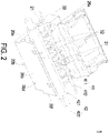
- FIG. 2 is a schematic perspective view illustrating the cable connection device of FIG. 1 , wherein an upper casing part and a lower casing part of the cable connection device are partially separated from each other.
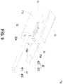
- FIG. 3 is a schematic exploded view illustrating the cable connection device of FIG. 2 .
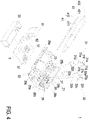
- FIG. 4 is a schematic exploded view illustrating the cable connection device of FIG. 2 and taken along another viewpoint.
- the cable connection device 1 is applied to a charging device (not shown) for charging a load (not shown).
- the cable connection device 1 is applied to a charging device of an electric vehicle for charging the electric vehicle.
- the cable connection device 1 includes a casing 2, at least one first connection component 31, at least one second connection component 32, a first power cable 41, a second power cable 42, a circuit board 5, a control element 61 and a connection cable 62.
- the casing 2 includes a first accommodation space 21, a second accommodation space 22 and at least one channel 23, as shown in FIG. 4 .
- the first accommodation space 21 and the second accommodation space 22 are separated from each other by a partition plate 24 and disposed beside two sides of the partition plate 24, respectively.
- the channel 23 runs through the partition plate 24 and in communication between the first accommodation space 21 and the second accommodation space 22.
- the number of the channel 23 is corresponding to the sum of the number of the first connection component 31 and the number of the second connection component 32. In this embodiment, the number of the first connection component 31 is two.
- the number of the second connection component 32 is two.
- the number of the channel 23 is four.
- Each first connection component 31 is made of conductive material and penetrated through the corresponding channel 23.
- Each first connection component 31 includes a clamping part 31a and a first conductive part 31b opposite to each other.
- the clamping part 31a is constituted by one end of the first connection component 31 far away from the partition plate 24.
- the clamping part 31a is disposed within the first accommodation space 21.
- the first conductive part 31b is disposed within the second accommodation space 22.
- the first power cable 41 receives a control signal of the charging device and transmits the control signal to the load. At least portion of the first power cable 41 is disposed within the first accommodation space 21. The other portion of the first power cable 41 is exposed to the exterior of the casing 2.
- the first power cable 41 includes an insulating sleeve 411 and a wire core 412.
- the insulating sleeve 411 of the first power cable 41 covers the outer periphery of the wire core 412, as shown in FIG. 3 .
- the wire core 412 is made of conductive material and transmits the control signal of the charging device to the load.
- the clamping part 31a of the first connection component 31 clamps the first power cable 41 disposed within the first accommodation space 21 and partially pierces the insulating sleeve 411 of the first power cable 41, so that the clamping part 31a of the first connection component 31 is electrically connected with the wire core 412 of the first power cable 41.
- Each second connection component 32 is made of conductive material and penetrated through the corresponding channel 23.
- Each second connection component 32 includes a clamping part 32a and a first conductive part 32b opposite to each other.
- the clamping part 32a is constituted by one end of the second connection component 32 far away from the partition plate 24.
- the clamping part 32a is disposed within the first accommodation space 21.
- the first conductive part 32b is disposed within the second accommodation space 22.
- the second power cable 42 is electrically connected with ground. At least portion of the second power cable 42 is disposed within the first accommodation space 21.
- the other portion of the second power cable 42 is exposed to the exterior of the casing 2.
- the second power cable 42 includes an insulating sleeve 421 and a wire core 422.
- the insulating sleeve 421 of the second power cable 42 covers the outer periphery of the wire core 422.
- the wire core 422 is made of conductive material and electrically connected with ground.
- the clamping part 32a of the second connection component 32 clamps the second power cable 42 disposed within the first accommodation space 21 and partially pierces the insulating sleeve 421 of the second power cable 42, so that the clamping part 32a of the second connection component 32 is electrically connected with the wire core 422 of the second power cable 42.
- the circuit board 5 is disposed within the second accommodation space 22, as shown in FIG. 4 .
- the circuit board 5 includes at least one second conductive part 51.
- the second conductive part 51 is a resilient contact piece made of conductive material and disposed on one side of the circuit board 5 adjacent to the partition plate 24.
- the number of the second conductive part 51 is corresponding to the sum of the number of the first connection component 31 and the number of the second connection component 32.
- the number of the second conductive part 51 is four, as shown in FIG. 4 .
- the positions of the four second conductive parts 51 are corresponding to the positions of the two first conductive parts 31b of the first connection component 31 and the positions of the two first conductive parts 32b of the second connection component 32, respectively.
- the four second conductive parts 51 are engaged with the corresponding engagement parts (not shown) of the casing 2, respectively, so that the circuit board 5 is fixed within the second accommodation space 22 of the casing 2.
- Each engagement part is in communication with the corresponding channel 23.
- Two of the four second conductive parts 51 are contacted and engaged with the corresponding first conductive parts 31b of the first connection component 31 through the corresponding engagement parts, respectively.
- the other two of the four second conductive parts 51 are contacted and engaged with the corresponding first conductive part 32b of the second connection component 32 through the corresponding engagement part, respectively.
- the control element 61 transmits the control signal of the charging device to the load and controls the load.
- the connection cable 62 is connected between the control element 61 and the circuit board 5.
- the connection cable 62 is electrically connected with the second conductive part 51 through the conductive wire within the circuit board 5.
- the control signal transmitted by the control element 61 is transmitted to the corresponding first conductive part 31b of the first connection component 31 through the second conductive part 51.
- the control signal transmitted by the control element 61 is transmitted to the wire core 412 of the first power cable 41 through the clamping part 31a of the first connection component 31, so that the load is controlled by the control signal.
- the control element 61 transmits the current needed to be grounded to the corresponding first conductive part 32b of the second connection component 32 through the second conductive part 51.
- the current is transmitted to the wire core 422 of the second power cable 42 through the clamping part 32a of the second connection component 32, so that the current is grounded.
- the cable connection device 1 of the present disclosure includes the first connection component 31 and the second connection component 32.
- the clamping part 31a, 31b of each connection component 31, 32 is contacted with the corresponding wire core 412, 422 of the power cable 41, 42.
- the first conductive part 31b, 32b of each connection component 31, 32 is contacted with the second conductive part 51 of the circuit board 5, so that the first conductive part 31b, 32b of each connection component 31, 32 is electrically connected with the control element 61.
- the control element and the signal source of the conventional charging device are connected with each other by utilizing soldering process, and the control element and the ground wire of the conventional charging device are connected with each other by utilizing riveting process.
- connection component 31, 32 of the cable connection device 1 of the present disclosure is connected with the wire core 412, 422 by piercing the power cable 41, 42, and the connection component 31, 32 of the cable connection device 1 of the present disclosure is contacted with the circuit board 5. Consequently, the cable connection device 1 of the present disclosure does not use soldering process or riveting process additionally.
- the power cable 41, 42 or the circuit board 5 need to be replaced, the power cable 41, 42 and the circuit boar 5 can be replaced by simply disassembling.
- the assembling process of the cable connection device 1 of the present disclosure is simple. The stability and the production yield of the cable connection device 1 are increased. The manufacturing cost of the cable connection device 1 is reduced.
- connection between the first power cable 41 and the first connection component 31 i.e., the clamping part 31a of the first connection component 31
- connection between the second power cable 42 and the second connection component 32 i.e., the clamping part 32a of the second connection component 32
- the casing 2 includes a first lateral surface 20a, a second lateral surface 20b, a third lateral surface 20c, a fourth lateral surface 20d, a fifth lateral surface 20e and a sixth lateral surface 20f.
- the first lateral surface 20a and the second lateral surface 20b are opposite to each other.
- the third lateral surface 20c and the fourth lateral surface 20d are opposite to each other and disposed between the first lateral surface 20a and the second lateral surface 20b.
- the fifth lateral surface 20e and the sixth lateral surface 20f are opposite to each other, disposed between the first lateral surface 20a and the second lateral surface 20b, and disposed between the third lateral surface 20c and the fourth lateral surface 20d.
- the clamping part 31a of the first connection component 31 includes a first surface 31c, a second surface 31d, a first groove 31e and two insertion parts 31f.
- the first surface 31c and the second surface 31d of the clamping part 31a of the first connection component 31 are opposite to each other.
- the first groove 31e is concavely formed by one side of the clamping part 31a adjacent to the first lateral surface 20a of the casing 2 for accommodating the first power cable 41.
- the clamping part 31a clamps the first power cable 41, so that the first power cable 41 is fixed within the first groove 31e.
- the two insertion parts 31f are disposed beside two sides of the first groove 31e and connected with the first groove 31e, respectively.
- each insertion part 31f includes an inclined surface 31g.
- the inclined surface 31g is adjacent to the first lateral surface 20a of the casing 2 and disposed between the first surface 31c and the second surface 31d.
- the inclined surface 31g is inclined from the first surface 31c toward the second surface 31d.
- Each insertion part 31f pierces the insulating sleeve 411 of the first power cable 41 through the corresponding inclined surface 31g.
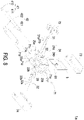
- FIG. 5 is a schematic perspective view illustrating a portion of the connection component of the cable connection device of FIG. 2 .
- a first angle ⁇ 1 is formed between the first surface 31c of the clamping part 31a of the first connection component 31 and the inclined surface 31g.
- a second angle ⁇ 2 is formed between the second surface 31d of the clamping part 31a of the first connection component 31 and the inclined surface 31g.
- the first angle ⁇ 1 is less than the second angle ⁇ 2.
- the first angle ⁇ 1 is 45 degrees
- the second angle ⁇ 2 is 135 degrees.
- the clamping part 32a of the second connection component 32 includes a first surface 32c, a second surface 32d, a first groove 32e and two insertion parts 32f.
- the first surface 32c and the second surface 32d of the clamping part 32a of the second connection component 32 are opposite to each other.
- the first groove 32e is concavely formed by one side of the clamping part 32a adjacent to the first lateral surface 20a of the casing 2 for accommodating the second power cable 42.
- the clamping part 32a clamps the second power cable 42, so that the second power cable 42 is fixed within the first groove 32e.
- the two insertion parts 32f are disposed beside two sides of the first groove 32e and connected with the first groove 32e, respectively.
- each insertion part 32f includes an inclined surface 32g.
- the inclined surface 32g is adjacent to the first lateral surface 20a of the casing 2 and disposed between the first surface 32c and the second surface 32d.
- the inclined surface 32g is inclined from the first surface 32c toward the second surface 32d.
- Each insertion part 32f pierces the insulating sleeve 421 of the second power cable 42 through the corresponding inclined surface 32g.
- a first angle ⁇ 3 is formed between the first surface 32c of the clamping part 32a of the second connection component 32 and the inclined surface 32g.
- a second angle ⁇ 4 is formed between the second surface 32d of the clamping part 32a of the second connection component 32 and the inclined surface 32g.
- the first angle ⁇ 3 is less than the second angle ⁇ 4.
- the first angle ⁇ 3 is 45 degrees, and the second angle ⁇ 4 is 135 degrees.
- FIG. 6 is an exploded schematic front view illustrating the cable connection device of FIG. 2 .
- the first groove 31e of the clamping part 31a of the first connection component 31 has a first groove width R1.
- the first groove width R1 is defined as the distance between a first connection edge and a second connection edge.
- the first connection edge is the connection between the inclined surface 31g of one of the two insertion parts 31f of the clamping part 31a of the first connection component 31 located at the left side of FIG. 5 and the first groove 31e.
- the second connection edge is the connection between the inclined surface 31g of the other one of the two insertion parts 31f of the clamping part 31a of the first connection component 31 located at the right side of FIG. 5 and the first groove 31e.
- the first groove width R1 of the first connection component 31 is less than or equal to the wire diameter d1 of the wire core 412 of the first power cable 41, so that the two insertion parts 31f are inserted into the insulating sleeve 411 of the first power cable 41 and contacted with the wire core 412 of the first power cable 41 when the first power cable 41 is accommodated in the first groove 31e.
- the first groove 32e of the clamping part 32a of the second connection component 32 has a first groove width R2.
- the first groove width R2 is defined as the distance between a third connection edge and a fourth connection edge.
- the third connection edge is the connection between the inclined surface 32g of one of the two insertion parts 32f of the clamping part 32a of the second connection component 32 located at the left side of FIG. 5 and the first groove 32e.
- the fourth connection edge is the connection between the inclined surface 32g of the other one of the two insertion parts 32f of the clamping part 32a of the second connection component 32 located at the right side of FIG. 5 and the first groove 32e.
- the first groove width R2 of the second connection component 32 is less than or equal to the wire diameter d2 of the wire core 422 of the second power cable 42, so that the two insertion parts 32f are inserted into the insulating sleeve 421 of the second power cable 42 and contacted with the wire core 422 of the second power cable 42 when the second power cable 42 is accommodated in the first groove 32e.
- the casing 2 includes at least one first hole 25a and at least one second hole 25b.
- the number of the first hole 25a is two.
- the two first holes 25a are disposed on the fifth lateral surface 25e of the casing 2.
- the number of the second hole 25b is two.
- the two second holes 25b are disposed on the sixth lateral surface 20f of the casing 2.
- the positions of the two first holes 25a are corresponding to the positions of the two second holes 25b, respectively.
- the diameter M1 of one of the two first holes 25a located at the left side of FIG. 6 is equal to the diameter of the corresponding second hole 25b.
- the diameter M1 of one of the two first holes 25a and the diameter of the corresponding second hole 25b are greater than the wire diameter D1 of the first power cable 41, respectively.
- the diameter M2 of the other one of the two first holes 25a located at the right side of FIG. 6 is equal to the diameter of the corresponding second hole 25b.
- the diameter M2 of the other one of the two first holes 25a and the diameter of the corresponding second hole 25b are greater than the wire diameter D2 of the second power cable 42, respectively.
- the first groove 31e of the first connection component 31 is disposed between the corresponding first hole 25a and the corresponding second hole 25b.
- the shortest distance between the first groove 31e of the first connection component 31 and the second lateral surface 20b of the casing 2 is greater than or equal to the shortest distance between the corresponding first hole 25a located at the left side of FIG. 6 and the second lateral surface 20b of the casing 2.
- the shortest distance between the first groove 31e of the first connection component 31 and the second lateral surface 20b of the casing 2 is greater than or equal to the shortest distance between the corresponding second hole 25b and the second lateral surface 20b of the casing 2. Consequently, the edge of the casing 2 constituted to the first hole 25a and the edge of the casing 2 constituted to the second hole 25b do not block the first power cable 41 to be accommodated in the first groove 31e.
- the first groove 32e of the second connection component 32 is disposed between the corresponding first hole 25a and the corresponding second hole 25b.
- the shortest distance between the first groove 32e of the second connection component 32 and the second lateral surface 20b of the casing 2 is greater than or equal to the shortest distance between the corresponding first hole 25a located at the right side of FIG. 6 and the second lateral surface 20b of the casing 2.
- the shortest distance between the first groove 32e of the second connection component 32 and the second lateral surface 20b of the casing 2 is greater than or equal to the shortest distance between the corresponding second hole 25b and the second lateral surface 20b of the casing 2. Consequently, the edge of the casing 2 constituted to the first hole 25a and the edge of the casing 2 constituted to the second hole 25b do not block the second power cable 42 to be accommodated in the first groove 32e.
- the casing 2 includes an upper casing part 26a, a lower casing part 26b, at least one first fixing part 27 and at least one second fixing part 28.
- the upper casing part 26a and the lower casing part 26b are opposite to each other and assembled to each other.
- the outer surface of the upper casing part 26a is formed as the first lateral surface 20a of the casing 2.
- the three outer surfaces of the lower casing part 26b are formed as the second lateral surface 20b, the third lateral surface 20c and the fourth lateral surface 20d of the casing 2, respectively.
- the connection between the upper casing part 26a and the lower casing part 26b is formed by the turning side between the first lateral surface 20a and the third lateral surface 20c of the casing 2.
- the upper casing part 26a and the lower casing part 26b are assembled with each other or separated from each other through the turning side between the first lateral surface 20a and the third lateral surface 20c of the casing 2.
- the number of the first fixing part 27 is corresponding to the number of the first connection component 31. As shown in FIG. 3 , the number of the first fixing part 27 and the number of the first connection component 31 are two, respectively.
- Each first fixing part 27 includes a plurality of fixing walls 27a and at least one second groove 27b. In this embodiment, each first fixing part 27 includes three fixing walls 27a and two second grooves 27b.
- the three fixing walls 27a of the first fixing part 27 are formed and extended from the lower casing part 26b constituted to the second lateral surface 20b of the casing 2 toward the upper casing part 26a.
- the space formed between the three fixing walls 27a and the lower casing part 26b constituted to the third lateral surface 20c of the casing 2 is in communication with the corresponding channel 23.
- the two second grooves 27b are disposed on the two fixing walls 27a parallel to the sixth lateral surface 20f of the casing 2, respectively.
- Each second groove 27b is concavely formed by one side of the corresponding fixing wall 27a adjacent to the first lateral surface 20a of the casing 2.
- One of the two first holes 25a adjacent to the third lateral surface 20c of the casing 2, the second groove 27b of the first fixing part 27, the first groove 31e of the first connection component 31 and one of the two second holes 25b adjacent to the third lateral surface 20c of the casing 2 are aligned to a straight line.
- Portion of the first power cable 41 is disposed in the second groove 27b of the first fixing part 27 and the first groove 31e of the first connection component 31.
- a second groove width of the second groove 27b of the first fixing part 27 is greater than or equal to the wire diameter D1 of the first power cable 41, so that portion of the first power cable 41 is disposed in the second groove 27b of the first fixing part 27.
- the number of the second fixing part 28 is corresponding to the number of the second connection component 32. As shown in FIG. 3 , the number of the second fixing part 28 and the number of the second connection component 32 are two, respectively.
- Each second fixing part 28 includes a plurality of fixing walls 28a and at least one second groove 28b. In this embodiment, each second fixing part 28 includes three fixing walls 28a and two second grooves 28b.
- the three fixing walls 28a of the second fixing part 28 is formed and extended from the lower casing part 26b constituted to the second lateral surface 20b of the casing 2 toward the upper casing part 26a.
- the space formed between the three fixing walls 28a and the lower casing part 26b constituted to the fourth lateral surface 20d of the casing 2 are in communication with the corresponding channel 23.
- the two second grooves 28b are disposed on the two fixing walls 28a parallel to the sixth lateral surface 20f of the casing 2, respectively.
- Each second groove 28b is concavely formed by one side of the corresponding fixing wall 28a adjacent to the first lateral surface 20a of the casing 2.
- One of the two first holes 25a adjacent to the fourth lateral surface 20d of the casing 2, the second groove 28b of the second fixing part 28, the first groove 32e of the second connection component 32 and one of the two second holes 25b adjacent to the fourth lateral surface 20d of the casing 2 are aligned to a straight line.
- Portion of the second power cable 42 is disposed in the second groove 28b of the second fixing part 28 and the first groove 32e of the second connection component 32.
- a second groove width of the second groove 28b of the second fixing part 28 is greater than or equal to the wire diameter D2 of the second power cable 42, so that portion of the second power cable 42 is disposed in the second groove 28b of the second fixing part 28.
- the cable connection device 1 includes a covering part 33, as shown in FIG. 4 .
- the covering part 33 is disposed on the third lateral surface 20c of the casing 2 for covering the second accommodation space 22, so that the circuit board 5 is sealed in the second accommodation space 22.
- FIG. 7 is a schematic perspective view illustrating a cable connection device according to a second embodiment of the present disclosure.
- FIG. 8 is a schematic exploded view illustrating the cable connection device of FIG. 7 .
- FIG. 9 is a schematic perspective view illustrating the cable connection device of FIG. 7 and taken along another viewpoint.
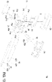
- FIG. 10 is a schematic exploded view illustrating the cable connection device of FIG. 9 .
- the casing 2 of the cable connection device 1a of this embodiment includes a first accommodation space 21, a second accommodation space 22, a third accommodation space 29 and two partition plates 24.
- the two partition plates 24 are referred to as a first partition plate 24a and a second partition plate 24b.
- the first accommodation space 21 and the second accommodation space 22 are separated by the first partition plate 24a located at the left side of FIG. 8 , and the first accommodation space 21 and the second accommodation space 22 are disposed beside two sides of the first partition plate 24a, respectively.
- the second accommodation space 22 and the third accommodation space 29 are separated by the second partition plate 24b located at the right side of FIG. 8 , and the second accommodation space 22 and the third accommodation space 29 are disposed beside two sides of the second partition plate 24b, respectively.
- the second accommodation space 22 is disposed between the first accommodation space 21 and the third accommodation space 29.
- the casing 2 of the cable connection device 1a of this embodiment includes a first channel 23a and a second channel 23b, as shown in FIGS. 8 and 10 .
- the first channel 23a runs through the first partition plate 24a and in communication between the first accommodation space 21 and the second accommodation space 22.
- the second channel 23b runs through the second partition plate 24b and in communication between the second accommodation space 22 and the third accommodation space 29.
- first connection component, the second connection component, the first power cable and the second power cable of the first embodiment are disposed in the same accommodation space.
- first connection component 31 and the first power cable 41 of the cable connection device 1a of this embodiment are disposed in the first accommodation space 21.
- the second connection component 32 and the second power cable 42 are disposed in the third accommodation space 29.
- the first connection component 31 of the cable connection device 1a is penetrated through the first channel 23a.
- the clamping part 31a of the first connection component 31 is formed by one end of the first connection component 31 away from the first partition plate 24a.
- the clamping part 31a of the first connection component 31 is disposed in the first accommodation space 21.
- the first conductive part 31b of the first connection component 31 is disposed in the second accommodation space 22.
- the second connection component 32 of the cable connection device 1a is penetrated through the second channel 23b.
- the clamping part 32a of the second connection component 32 is formed by one end of the second connection component 32 away from the second partition plate 24b.
- the clamping part 32a of the second connection component 32 is disposed in the third accommodation space 29.
- the first conductive part 32b of the second connection component 32 is disposed in the second accommodation space 22.
- the structure of the first connection component 31 and the structure of the second connection component 32 of this embodiment are similar to the structure of the first connection component 31 and the structure of the second connection component 32 of FIG. 3 , and are not redundantly described herein.
- the circuit board 5 is disposed in the second accommodation space 22, and disposed between the first connection component 31 and the second connection component 32. Moreover, the circuit board 5 includes a plurality of second conductive parts 51.
- the circuit board 5 includes four second conductive parts 51. Two of the four second conductive parts 51 are contacted with the two first conductive parts 31b of the first connection component 31, respectively. The other two of the four second conductive parts 51 are contacted with the two first conductive parts 32b of the second connection component 32. The two second conductive parts 51 contacted with the two first conductive parts 31b of the first connection component 31 and the two second conductive parts 51 contacted with the two first conductive parts 32b of the second connection component 32 are disposed on the two opposite sides of the circuit board 5.
- the casing 2 of cable connection device 1 of the first embodiment is constituted by the upper casing part 26a and the lower casing part 26b.
- the casing 2 of the cable connection device 1a of this embodiment includes a main body 71, a first covering part 72, a second covering part 73 and a third covering part 74 assembled with each other.
- the main body 71 includes a first lateral surface 71a, a second lateral surface 71b, a third lateral surface 71c, a fourth lateral surface 71d, a fifth lateral surface 71e and a sixth lateral surface 71f. As shown in FIGS.
- the first lateral surface 71a and the second lateral surface 71b of the main body 71 are opposite to each other.
- the third lateral surface 71c and the fourth lateral surface 71d of the main body 71 are opposite to each other and disposed between the first lateral surface 71a and the second lateral surface 71b.
- the fifth lateral surface 71e and the sixth lateral surface 71f are opposite to each other, disposed between the first lateral surface 71a and the second lateral surface 71b, and disposed between the third lateral surface 71c and the fourth lateral surface 71d.
- the first covering part 72 is disposed on the third lateral surface 71c of the main body 71 for covering the first accommodation space 21.
- the second covering part 73 is disposed on the first lateral surface 71a of the main body 71 for covering the second accommodation space 22.
- the third covering part 74 is disposed on the fourth lateral surface 71d of the main body 71 for covering the third accommodation space 29.
- the casing 2 includes a plurality of first holes 25a and a plurality of second holes 25b.
- the casing 2 includes two first holes 25a and two second holes 25b.
- the two first holes 25a are disposed on the fifth lateral surface 71e of the main body 71.
- One of the two first holes 25a is formed by assembling one end of the first covering part 72 with the third lateral surface 71c of the main body 71.
- the other one of the two first holes 25a is formed by assembling one end of the third covering part 74 with the fourth lateral surface 71d of the main body 71.
- the two second holes 25b are disposed on the sixth lateral surface 71f of the main body 71.
- One of the two second holes 25b is formed by assembling the other end of the first covering part 72 with the third lateral surface 71c of the main body 71.
- the other one of the two second holes 25b is formed by assembling the other end of the third covering part 74 with the fourth lateral surface 71d of the main body 71.
- the positions of the two first holes 25a are corresponding to the positions of the two second holes 25b, respectively.
- One of the two first holes 25a and one of the two second holes 25b are disposed beside two sides of the first accommodation space 21.
- the other one of the two first holes 25a and the other one of the two second holes 25b are disposed beside two sides of the third accommodation space 29.
- the first power cable 41 is disposed in the first accommodation space 21 and exposed to the exterior of the casing 2 through the corresponding first hole 25a and the corresponding second hole 25b.
- the wire width of the first power cable 41 is less than the diameter of the corresponding first hole 25a and the diameter of the corresponding second hole 25b.
- the second power cable 42 is disposed in the third accommodation space 29 and exposed to the exterior of the casing 2 through the corresponding first hole 25a and the corresponding second hole 25b.
- the wire width of the second power cable 42 is less than the diameter of the corresponding first hole 25a and the diameter of the corresponding second hole 25b.
- the present disclosure provides a cable connection device.
- the cable connection device includes two connection components.
- the clamping part of each connection component is contacted with the corresponding wire core of the power cable.
- the first conductive part of each connection component is contacted with the second conductive part of the circuit board, so that the first conductive part of each connection component is electrically connected with the control element.
- the control element and the signal source of the conventional charging device are connected with each other by utilizing soldering process, and the control element and the ground wire of the conventional charging device are connected with each other by utilizing riveting process.
- connection component of the cable connection device of the present disclosure is connected with the wire core by piercing the power cable, and the connection component of the cable connection device of the present disclosure is contacted with the circuit board. Consequently, the cable connection device of the present disclosure does not use soldering process or riveting process additionally.
- the power cable and the circuit board need to be replaced, the power cable and the circuit board can be replaced by simply disassembling.
- the assembling process of the cable connection device of the present disclosure is simple.
- the stability and the production yield of the cable connection device are increased.
- the manufacturing cost of the cable connection device is reduced.
- the connection between the first power cable and the first connection component and the connection between the second power cable and the second connection component are disposed within the casing. Consequently, the connections may not be impacted by the external force, so that the connections are stable and not easy to separate.
Landscapes
- Engineering & Computer Science (AREA)
- Microelectronics & Electronic Packaging (AREA)
- Details Of Connecting Devices For Male And Female Coupling (AREA)
- Multi-Conductor Connections (AREA)
Abstract
A cable connection device (1) is provided. The cable connection device (1) includes a casing (2), a connection component (31, 32), a power cable (41, 42) and a circuit board (5). The casing (2) includes a first accommodation space (21), a second accommodation space (22) and a channel (23). The channel (23) is in communication between the first accommodation space (21) and the second accommodation space (22). The connection component (31, 32) is penetrated through the channel (23) and includes a clamping part (31a, 32a) disposed in the first accommodation space (21) and a first conductive part (31b, 32b) disposed in the second accommodation space (22). Portion of the power cable (41, 42) is disposed in the first accommodation space (21). The clamping part (31a, 32a) clamps the power cable (41, 42) and partially pierces the insulating sleeve (411, 421), so that the clamping part (31a, 32a) is connected with the wire core (412, 422). The circuit board (5) is disposed in the second accommodation space (22) and comprises second conductive part (51). The second conductive part (51) is contacted with the first conductive part (31b, 32b).
Description
- The present disclosure relates to a cable connection device, and more particularly to a cable connection device with high stability.
- With increasing development of electric system and environmental consciousness, it is a trend to replace the fossil energy with clean electric energy. Demand for private electric vehicle and electric engineering tools is increased gradually. Accordingly, the charging device used to charge the private electric vehicle and the electric engineering tools is gradually popular. The safety of the charging device is an issue that must be paid attention to. The charging end of the charging device provides the power with high current and high voltage, and the power receiving end of the charging device receives the power with high current and high voltage. Consequently, it is very important to maintain the connection stability between the control element and the signal source of the charging device, and maintain the connection stability between the control element and the ground wire. The control element and the signal source of the conventional charging device are connected with each other by utilizing soldering process. The control element and the ground wire of the conventional charging device are connected with each other by utilizing riveting process. However, the aforementioned method is more complicated and the stability of the connection is not satisfied.
- Therefore, there is a need of providing a cable connection device in order to overcome the above drawbacks.
- The present disclosure provides a cable connection device in order to increase the stability of connection.
- In accordance with an aspect of the present disclosure, a cable connection device is provided. The cable connection device includes a casing, at least one connection component, at least one power cable and a circuit board. The casing includes a first accommodation space, a second accommodation space and at least one channel. The channel is in communication between the first accommodation space and the second accommodation space. The at least one connection component is penetrated through the at least one channel and each connection component includes a clamping part and a first conductive part. The clamping part and the first conductive part are opposite to each other. The clamping part is disposed in the first accommodation space. The first conductive part is disposed in the second accommodation space. At least portion of the at least one power cable is disposed in the first accommodation space. Each power cable includes an insulating sleeve and a wire core. An outer periphery of the wire core is covered by the insulating sleeve. The clamping part clamps the at least one power cable and partially pierces the insulating sleeve, so that the clamping part is electrically connected with the wire core. The circuit board is disposed in the second accommodation space and includes at least one second conductive part. The at least one second conductive part is contacted with the first conductive part.
- In accordance with another aspect of the present disclosure, a cable connection device is provided. The cable connection device includes a casing, a first connection component, a second connection component, a first power cable, a second power cable and a circuit board. The casing includes a first accommodation space, a second accommodation space, a third accommodation space, a first channel and a second channel. The first channel is in communication between the first accommodation space and the second accommodation space. The second channel is in communication between the second accommodation space and the third accommodation space. The first connection component is penetrated through the first channel and includes a clamping part and a first conductive part. The clamping part and the first conductive part of the first connection component are opposite to each other. The clamping part of the first connection component is disposed in the first accommodation space. The first conductive part of the first connection component is disposed in the second accommodation space. The second connection component is penetrated through the second channel and includes a clamping part and a first conductive part. The clamping part and the first conductive part of the second connection component are opposite to each other. The clamping part of the second connection component is disposed in the third accommodation space. The first conductive part of the second connection component is disposed in the second accommodation space. At least portion of the first power cable is disposed in the first accommodation space. The first power cable includes an insulating sleeve and a wire core. An outer periphery of the wire core of the first power cable is covered by the insulating sleeve. The clamping part of the first connection component clamps the first power cable and partially pierces the insulating sleeve, so that the clamping part of the first connection component is electrically connected with the wire core of the first power cable. At least portion of the second power cable is disposed in the third accommodation space. The second power cable includes an insulating sleeve and a wire core. An outer periphery of the wire core of the second power cable is covered by the insulating sleeve. The clamping part of the second connection component clamps the second power cable and partially pierces the insulating sleeve, so that the clamping part of the second connection component is electrically connected with the wire core of the second power cable. The circuit board is disposed in the second accommodation space and includes a plurality of second conductive parts. The plurality of second conductive parts are contacted with the first conductive part of the first connection component and the second conductive part of the second connection component, respectively.
- The above contents of the present disclosure will become more readily apparent to those ordinarily skilled in the art after reviewing the following detailed description and accompanying drawings, in which:
-
-
FIG. 1 is a schematic perspective view illustrating a cable connection device according to a first embodiment of the present disclosure; -
FIG. 2 is a schematic perspective view illustrating the cable connection device ofFIG. 1 , wherein an upper casing part and a lower casing part of the cable connection device are partially separated from each other; -
FIG. 3 is a schematic exploded view illustrating the cable connection device ofFIG. 2 ; -
FIG. 4 is a schematic exploded view illustrating the cable connection device ofFIG. 2 and taken along another viewpoint; -
FIG. 5 is a schematic perspective view illustrating a portion of the connection component of the cable connection device ofFIG. 2 ; -
FIG. 6 is an exploded schematic front view illustrating the cable connection device ofFIG. 2 ; -
FIG. 7 is a schematic perspective view illustrating a cable connection device according to a second embodiment of the present disclosure; -
FIG. 8 is a schematic exploded view illustrating the cable connection device ofFIG. 7 ; -
FIG. 9 is a schematic perspective view illustrating the cable connection device ofFIG. 7 and taken along another viewpoint; and -
FIG. 10 is a schematic exploded view illustrating the cable connection device ofFIG. 9 . - The present disclosure will now be described more specifically with reference to the following embodiments. It is to be noted that the following descriptions of preferred embodiments of this disclosure are presented herein for purpose of illustration and description only. It is not intended to be exhaustive or to be limited to the precise form disclosed.
-
FIG. 1 is a schematic perspective view illustrating a cable connection device according to a first embodiment of the present disclosure.FIG. 2 is a schematic perspective view illustrating the cable connection device ofFIG. 1 , wherein an upper casing part and a lower casing part of the cable connection device are partially separated from each other.FIG. 3 is a schematic exploded view illustrating the cable connection device ofFIG. 2 .FIG. 4 is a schematic exploded view illustrating the cable connection device ofFIG. 2 and taken along another viewpoint. As shown inFIGS. 1 to 4 , in the embodiment, thecable connection device 1 is applied to a charging device (not shown) for charging a load (not shown). For example, thecable connection device 1 is applied to a charging device of an electric vehicle for charging the electric vehicle. Thecable connection device 1 includes acasing 2, at least onefirst connection component 31, at least onesecond connection component 32, afirst power cable 41, asecond power cable 42, acircuit board 5, acontrol element 61 and aconnection cable 62. - The
casing 2 includes afirst accommodation space 21, asecond accommodation space 22 and at least onechannel 23, as shown inFIG. 4 . Thefirst accommodation space 21 and thesecond accommodation space 22 are separated from each other by apartition plate 24 and disposed beside two sides of thepartition plate 24, respectively. Thechannel 23 runs through thepartition plate 24 and in communication between thefirst accommodation space 21 and thesecond accommodation space 22. The number of thechannel 23 is corresponding to the sum of the number of thefirst connection component 31 and the number of thesecond connection component 32. In this embodiment, the number of thefirst connection component 31 is two. The number of thesecond connection component 32 is two. The number of thechannel 23 is four. Eachfirst connection component 31 is made of conductive material and penetrated through the correspondingchannel 23. Eachfirst connection component 31 includes a clampingpart 31a and a firstconductive part 31b opposite to each other. The clampingpart 31a is constituted by one end of thefirst connection component 31 far away from thepartition plate 24. The clampingpart 31a is disposed within thefirst accommodation space 21. The firstconductive part 31b is disposed within thesecond accommodation space 22. Thefirst power cable 41 receives a control signal of the charging device and transmits the control signal to the load. At least portion of thefirst power cable 41 is disposed within thefirst accommodation space 21. The other portion of thefirst power cable 41 is exposed to the exterior of thecasing 2. Thefirst power cable 41 includes an insulatingsleeve 411 and awire core 412. The insulatingsleeve 411 of thefirst power cable 41 covers the outer periphery of thewire core 412, as shown inFIG. 3 . Thewire core 412 is made of conductive material and transmits the control signal of the charging device to the load. The clampingpart 31a of thefirst connection component 31 clamps thefirst power cable 41 disposed within thefirst accommodation space 21 and partially pierces the insulatingsleeve 411 of thefirst power cable 41, so that the clampingpart 31a of thefirst connection component 31 is electrically connected with thewire core 412 of thefirst power cable 41. - Each
second connection component 32 is made of conductive material and penetrated through the correspondingchannel 23. Eachsecond connection component 32 includes a clampingpart 32a and a firstconductive part 32b opposite to each other. The clampingpart 32a is constituted by one end of thesecond connection component 32 far away from thepartition plate 24. The clampingpart 32a is disposed within thefirst accommodation space 21. The firstconductive part 32b is disposed within thesecond accommodation space 22. Thesecond power cable 42 is electrically connected with ground. At least portion of thesecond power cable 42 is disposed within thefirst accommodation space 21. The other portion of thesecond power cable 42 is exposed to the exterior of thecasing 2. Thesecond power cable 42 includes an insulatingsleeve 421 and awire core 422. The insulatingsleeve 421 of thesecond power cable 42 covers the outer periphery of thewire core 422. Thewire core 422 is made of conductive material and electrically connected with ground. The clampingpart 32a of thesecond connection component 32 clamps thesecond power cable 42 disposed within thefirst accommodation space 21 and partially pierces the insulatingsleeve 421 of thesecond power cable 42, so that the clampingpart 32a of thesecond connection component 32 is electrically connected with thewire core 422 of thesecond power cable 42. - The
circuit board 5 is disposed within thesecond accommodation space 22, as shown inFIG. 4 . Thecircuit board 5 includes at least one secondconductive part 51. The secondconductive part 51 is a resilient contact piece made of conductive material and disposed on one side of thecircuit board 5 adjacent to thepartition plate 24. The number of the secondconductive part 51 is corresponding to the sum of the number of thefirst connection component 31 and the number of thesecond connection component 32. For example, the number of the secondconductive part 51 is four, as shown inFIG. 4 . The positions of the four secondconductive parts 51 are corresponding to the positions of the two firstconductive parts 31b of thefirst connection component 31 and the positions of the two firstconductive parts 32b of thesecond connection component 32, respectively. The four secondconductive parts 51 are engaged with the corresponding engagement parts (not shown) of thecasing 2, respectively, so that thecircuit board 5 is fixed within thesecond accommodation space 22 of thecasing 2. Each engagement part is in communication with the correspondingchannel 23. Two of the four secondconductive parts 51 are contacted and engaged with the corresponding firstconductive parts 31b of thefirst connection component 31 through the corresponding engagement parts, respectively. The other two of the four secondconductive parts 51 are contacted and engaged with the corresponding firstconductive part 32b of thesecond connection component 32 through the corresponding engagement part, respectively. - The
control element 61 transmits the control signal of the charging device to the load and controls the load. Theconnection cable 62 is connected between thecontrol element 61 and thecircuit board 5. Theconnection cable 62 is electrically connected with the secondconductive part 51 through the conductive wire within thecircuit board 5. The control signal transmitted by thecontrol element 61 is transmitted to the corresponding firstconductive part 31b of thefirst connection component 31 through the secondconductive part 51. The control signal transmitted by thecontrol element 61 is transmitted to thewire core 412 of thefirst power cable 41 through the clampingpart 31a of thefirst connection component 31, so that the load is controlled by the control signal. Moreover, thecontrol element 61 transmits the current needed to be grounded to the corresponding firstconductive part 32b of thesecond connection component 32 through the secondconductive part 51. The current is transmitted to thewire core 422 of thesecond power cable 42 through the clampingpart 32a of thesecond connection component 32, so that the current is grounded. - As mentioned above, the
cable connection device 1 of the present disclosure includes thefirst connection component 31 and thesecond connection component 32. The clampingpart connection component corresponding wire core power cable conductive part connection component conductive part 51 of thecircuit board 5, so that the firstconductive part connection component control element 61. The control element and the signal source of the conventional charging device are connected with each other by utilizing soldering process, and the control element and the ground wire of the conventional charging device are connected with each other by utilizing riveting process. In comparison with the conventional charging device, theconnection component cable connection device 1 of the present disclosure is connected with thewire core power cable connection component cable connection device 1 of the present disclosure is contacted with thecircuit board 5. Consequently, thecable connection device 1 of the present disclosure does not use soldering process or riveting process additionally. When thepower cable circuit board 5 need to be replaced, thepower cable circuit boar 5 can be replaced by simply disassembling. The assembling process of thecable connection device 1 of the present disclosure is simple. The stability and the production yield of thecable connection device 1 are increased. The manufacturing cost of thecable connection device 1 is reduced. Moreover, the connection between thefirst power cable 41 and the first connection component 31 (i.e., the clampingpart 31a of the first connection component 31) and the connection between thesecond power cable 42 and the second connection component 32 (i.e., the clampingpart 32a of the second connection component 32) are disposed within thefirst accommodation space 21 of thecasing 2. Consequently, the connections may not be impacted by external force, so that the connections are stable and not easy to separate. - Please refer to
FIGS. 1 to 4 again. Thecasing 2 includes a firstlateral surface 20a, a secondlateral surface 20b, a thirdlateral surface 20c, a fourthlateral surface 20d, a fifthlateral surface 20e and a sixthlateral surface 20f. The firstlateral surface 20a and the secondlateral surface 20b are opposite to each other. The thirdlateral surface 20c and the fourthlateral surface 20d are opposite to each other and disposed between the firstlateral surface 20a and the secondlateral surface 20b. The fifthlateral surface 20e and the sixthlateral surface 20f are opposite to each other, disposed between the firstlateral surface 20a and the secondlateral surface 20b, and disposed between the thirdlateral surface 20c and the fourthlateral surface 20d. - As shown in
FIG. 4 , the clampingpart 31a of thefirst connection component 31 includes afirst surface 31c, asecond surface 31d, afirst groove 31e and twoinsertion parts 31f. Thefirst surface 31c and thesecond surface 31d of the clampingpart 31a of thefirst connection component 31 are opposite to each other. Thefirst groove 31e is concavely formed by one side of the clampingpart 31a adjacent to the firstlateral surface 20a of thecasing 2 for accommodating thefirst power cable 41. The clampingpart 31a clamps thefirst power cable 41, so that thefirst power cable 41 is fixed within thefirst groove 31e. The twoinsertion parts 31f are disposed beside two sides of thefirst groove 31e and connected with thefirst groove 31e, respectively. When thefirst power cable 41 is accommodated in thefirst groove 31e, the twoinsertion parts 31f are inserted into the insulatingsleeve 411 of thefirst power cable 41, so that the twoinsertion parts 31f are contacted with thewire core 412 of thefirst power cable 41. For allowing the clampingpart 31a to pierce the insulatingsleeve 411 of thefirst power cable 41 easily, eachinsertion part 31f includes aninclined surface 31g. Theinclined surface 31g is adjacent to the firstlateral surface 20a of thecasing 2 and disposed between thefirst surface 31c and thesecond surface 31d. Theinclined surface 31g is inclined from thefirst surface 31c toward thesecond surface 31d. Eachinsertion part 31f pierces the insulatingsleeve 411 of thefirst power cable 41 through the correspondinginclined surface 31g. -
FIG. 5 is a schematic perspective view illustrating a portion of the connection component of the cable connection device ofFIG. 2 . As shown inFIGS. 4 and5 , a first angle θ1 is formed between thefirst surface 31c of the clampingpart 31a of thefirst connection component 31 and theinclined surface 31g. A second angle θ2 is formed between thesecond surface 31d of the clampingpart 31a of thefirst connection component 31 and theinclined surface 31g. The first angle θ1 is less than the second angle θ2. Preferably but not exclusively, the first angle θ1 is 45 degrees, and the second angle θ2 is 135 degrees. - As shown in
FIG. 4 , the clampingpart 32a of thesecond connection component 32 includes afirst surface 32c, asecond surface 32d, afirst groove 32e and twoinsertion parts 32f. Thefirst surface 32c and thesecond surface 32d of the clampingpart 32a of thesecond connection component 32 are opposite to each other. Thefirst groove 32e is concavely formed by one side of the clampingpart 32a adjacent to the firstlateral surface 20a of thecasing 2 for accommodating thesecond power cable 42. The clampingpart 32a clamps thesecond power cable 42, so that thesecond power cable 42 is fixed within thefirst groove 32e. The twoinsertion parts 32f are disposed beside two sides of thefirst groove 32e and connected with thefirst groove 32e, respectively. When thesecond power cable 42 is accommodated in thefirst groove 32e, the twoinsertion parts 32f are inserted into the insulatingsleeve 421 of thesecond power cable 42, so that the twoinsertion parts 32f are contacted with thewire core 422 of thesecond power cable 42. For allowing the clampingpart 32a to pierce the insulatingsleeve 421 of thesecond power cable 42 easily, eachinsertion part 32f includes aninclined surface 32g. Theinclined surface 32g is adjacent to the firstlateral surface 20a of thecasing 2 and disposed between thefirst surface 32c and thesecond surface 32d. Theinclined surface 32g is inclined from thefirst surface 32c toward thesecond surface 32d. Eachinsertion part 32f pierces the insulatingsleeve 421 of thesecond power cable 42 through the correspondinginclined surface 32g. - As shown in
FIG. 5 , a first angle θ3 is formed between thefirst surface 32c of the clampingpart 32a of thesecond connection component 32 and theinclined surface 32g. A second angle θ4 is formed between thesecond surface 32d of the clampingpart 32a of thesecond connection component 32 and theinclined surface 32g. The first angle θ3 is less than the second angle θ4. Preferably but not exclusively, the first angle θ3 is 45 degrees, and the second angle θ4 is 135 degrees. -
FIG. 6 is an exploded schematic front view illustrating the cable connection device ofFIG. 2 . As shown inFIGS. 1 to 4 and6 , thefirst groove 31e of the clampingpart 31a of thefirst connection component 31 has a first groove width R1. The first groove width R1 is defined as the distance between a first connection edge and a second connection edge. The first connection edge is the connection between theinclined surface 31g of one of the twoinsertion parts 31f of the clampingpart 31a of thefirst connection component 31 located at the left side ofFIG. 5 and thefirst groove 31e. The second connection edge is the connection between theinclined surface 31g of the other one of the twoinsertion parts 31f of the clampingpart 31a of thefirst connection component 31 located at the right side ofFIG. 5 and thefirst groove 31e. The first groove width R1 of thefirst connection component 31 is less than or equal to the wire diameter d1 of thewire core 412 of thefirst power cable 41, so that the twoinsertion parts 31f are inserted into the insulatingsleeve 411 of thefirst power cable 41 and contacted with thewire core 412 of thefirst power cable 41 when thefirst power cable 41 is accommodated in thefirst groove 31e. - The
first groove 32e of the clampingpart 32a of thesecond connection component 32 has a first groove width R2. The first groove width R2 is defined as the distance between a third connection edge and a fourth connection edge. The third connection edge is the connection between theinclined surface 32g of one of the twoinsertion parts 32f of the clampingpart 32a of thesecond connection component 32 located at the left side ofFIG. 5 and thefirst groove 32e. The fourth connection edge is the connection between theinclined surface 32g of the other one of the twoinsertion parts 32f of the clampingpart 32a of thesecond connection component 32 located at the right side ofFIG. 5 and thefirst groove 32e. The first groove width R2 of thesecond connection component 32 is less than or equal to the wire diameter d2 of thewire core 422 of thesecond power cable 42, so that the twoinsertion parts 32f are inserted into the insulatingsleeve 421 of thesecond power cable 42 and contacted with thewire core 422 of thesecond power cable 42 when thesecond power cable 42 is accommodated in thefirst groove 32e. - Please refer to
FIGS. 4 and6 again. Thecasing 2 includes at least onefirst hole 25a and at least onesecond hole 25b. In this embodiment, the number of thefirst hole 25a is two. The twofirst holes 25a are disposed on the fifth lateral surface 25e of thecasing 2. The number of thesecond hole 25b is two. The twosecond holes 25b are disposed on the sixthlateral surface 20f of thecasing 2. The positions of the twofirst holes 25a are corresponding to the positions of the twosecond holes 25b, respectively. The diameter M1 of one of the twofirst holes 25a located at the left side ofFIG. 6 is equal to the diameter of the correspondingsecond hole 25b. The diameter M1 of one of the twofirst holes 25a and the diameter of the correspondingsecond hole 25b are greater than the wire diameter D1 of thefirst power cable 41, respectively. When thefirst power cable 41 is accommodated in thefirst accommodation space 21, the two ends of thefirst power cable 41 are exposed to the exterior of thecasing 2 through the correspondingfirst hole 25a and the correspondingsecond hole 25b, respectively. The diameter M2 of the other one of the twofirst holes 25a located at the right side ofFIG. 6 is equal to the diameter of the correspondingsecond hole 25b. The diameter M2 of the other one of the twofirst holes 25a and the diameter of the correspondingsecond hole 25b are greater than the wire diameter D2 of thesecond power cable 42, respectively. When thesecond power cable 42 is accommodated in thefirst accommodation space 21, the two ends of thesecond power cable 42 are exposed to the exterior of thecasing 2 through the correspondingfirst hole 25a and the correspondingsecond hole 25b, respectively. - In this embodiment, the
first groove 31e of thefirst connection component 31 is disposed between the correspondingfirst hole 25a and the correspondingsecond hole 25b. The shortest distance between thefirst groove 31e of thefirst connection component 31 and the secondlateral surface 20b of thecasing 2 is greater than or equal to the shortest distance between the correspondingfirst hole 25a located at the left side ofFIG. 6 and the secondlateral surface 20b of thecasing 2. Moreover, the shortest distance between thefirst groove 31e of thefirst connection component 31 and the secondlateral surface 20b of thecasing 2 is greater than or equal to the shortest distance between the correspondingsecond hole 25b and the secondlateral surface 20b of thecasing 2. Consequently, the edge of thecasing 2 constituted to thefirst hole 25a and the edge of thecasing 2 constituted to thesecond hole 25b do not block thefirst power cable 41 to be accommodated in thefirst groove 31e. - The
first groove 32e of thesecond connection component 32 is disposed between the correspondingfirst hole 25a and the correspondingsecond hole 25b. The shortest distance between thefirst groove 32e of thesecond connection component 32 and the secondlateral surface 20b of thecasing 2 is greater than or equal to the shortest distance between the correspondingfirst hole 25a located at the right side ofFIG. 6 and the secondlateral surface 20b of thecasing 2. Moreover, the shortest distance between thefirst groove 32e of thesecond connection component 32 and the secondlateral surface 20b of thecasing 2 is greater than or equal to the shortest distance between the correspondingsecond hole 25b and the secondlateral surface 20b of thecasing 2. Consequently, the edge of thecasing 2 constituted to thefirst hole 25a and the edge of thecasing 2 constituted to thesecond hole 25b do not block thesecond power cable 42 to be accommodated in thefirst groove 32e. - Please refer to
FIGS. 2 to 4 . Thecasing 2 includes anupper casing part 26a, alower casing part 26b, at least one first fixingpart 27 and at least one second fixingpart 28. Theupper casing part 26a and thelower casing part 26b are opposite to each other and assembled to each other. The outer surface of theupper casing part 26a is formed as the firstlateral surface 20a of thecasing 2. The three outer surfaces of thelower casing part 26b are formed as the secondlateral surface 20b, the thirdlateral surface 20c and the fourthlateral surface 20d of thecasing 2, respectively. The connection between theupper casing part 26a and thelower casing part 26b is formed by the turning side between the firstlateral surface 20a and the thirdlateral surface 20c of thecasing 2. Theupper casing part 26a and thelower casing part 26b are assembled with each other or separated from each other through the turning side between the firstlateral surface 20a and the thirdlateral surface 20c of thecasing 2. - The number of the first fixing
part 27 is corresponding to the number of thefirst connection component 31. As shown inFIG. 3 , the number of the first fixingpart 27 and the number of thefirst connection component 31 are two, respectively. Each first fixingpart 27 includes a plurality of fixing walls 27a and at least one second groove 27b. In this embodiment, each first fixingpart 27 includes three fixing walls 27a and two second grooves 27b. The three fixing walls 27a of the first fixingpart 27 are formed and extended from thelower casing part 26b constituted to the secondlateral surface 20b of thecasing 2 toward theupper casing part 26a. The space formed between the three fixing walls 27a and thelower casing part 26b constituted to the thirdlateral surface 20c of thecasing 2 is in communication with the correspondingchannel 23. The two second grooves 27b are disposed on the two fixing walls 27a parallel to the sixthlateral surface 20f of thecasing 2, respectively. Each second groove 27b is concavely formed by one side of the corresponding fixing wall 27a adjacent to the firstlateral surface 20a of thecasing 2. One of the twofirst holes 25a adjacent to the thirdlateral surface 20c of thecasing 2, the second groove 27b of the first fixingpart 27, thefirst groove 31e of thefirst connection component 31 and one of the twosecond holes 25b adjacent to the thirdlateral surface 20c of thecasing 2 are aligned to a straight line. Portion of thefirst power cable 41 is disposed in the second groove 27b of the first fixingpart 27 and thefirst groove 31e of thefirst connection component 31. Two ends of thefirst power cable 41 are exposed to the exterior of thecasing 2 through thefirst hole 25a and thesecond hole 25b adjacent to the thirdlateral surface 20c of thecasing 2, respectively. A second groove width of the second groove 27b of the first fixingpart 27 is greater than or equal to the wire diameter D1 of thefirst power cable 41, so that portion of thefirst power cable 41 is disposed in the second groove 27b of the first fixingpart 27. - The number of the second fixing
part 28 is corresponding to the number of thesecond connection component 32. As shown inFIG. 3 , the number of the second fixingpart 28 and the number of thesecond connection component 32 are two, respectively. Each second fixingpart 28 includes a plurality of fixingwalls 28a and at least onesecond groove 28b. In this embodiment, each second fixingpart 28 includes three fixingwalls 28a and twosecond grooves 28b. The threefixing walls 28a of the second fixingpart 28 is formed and extended from thelower casing part 26b constituted to the secondlateral surface 20b of thecasing 2 toward theupper casing part 26a. The space formed between the three fixingwalls 28a and thelower casing part 26b constituted to the fourthlateral surface 20d of thecasing 2 are in communication with the correspondingchannel 23. The twosecond grooves 28b are disposed on the two fixingwalls 28a parallel to the sixthlateral surface 20f of thecasing 2, respectively. Eachsecond groove 28b is concavely formed by one side of the corresponding fixingwall 28a adjacent to the firstlateral surface 20a of thecasing 2. One of the twofirst holes 25a adjacent to the fourthlateral surface 20d of thecasing 2, thesecond groove 28b of the second fixingpart 28, thefirst groove 32e of thesecond connection component 32 and one of the twosecond holes 25b adjacent to the fourthlateral surface 20d of thecasing 2 are aligned to a straight line. Portion of thesecond power cable 42 is disposed in thesecond groove 28b of the second fixingpart 28 and thefirst groove 32e of thesecond connection component 32. Two ends of thesecond power cable 42 are exposed to the exterior of thecasing 2 through thefirst hole 25a and thesecond hole 25b adjacent to the fourthlateral surface 20d of thecasing 2, respectively. A second groove width of thesecond groove 28b of the second fixingpart 28 is greater than or equal to the wire diameter D2 of thesecond power cable 42, so that portion of thesecond power cable 42 is disposed in thesecond groove 28b of the second fixingpart 28. - In some embodiments, the
cable connection device 1 includes a coveringpart 33, as shown inFIG. 4 . The coveringpart 33 is disposed on the thirdlateral surface 20c of thecasing 2 for covering thesecond accommodation space 22, so that thecircuit board 5 is sealed in thesecond accommodation space 22. -
FIG. 7 is a schematic perspective view illustrating a cable connection device according to a second embodiment of the present disclosure.FIG. 8 is a schematic exploded view illustrating the cable connection device ofFIG. 7 .FIG. 9 is a schematic perspective view illustrating the cable connection device ofFIG. 7 and taken along another viewpoint.FIG. 10 is a schematic exploded view illustrating the cable connection device ofFIG. 9 . In comparison with thecasing 2 of thecable connection device 1 of the first embodiment only including two accommodation spaces and single partition plate, thecasing 2 of thecable connection device 1a of this embodiment includes afirst accommodation space 21, asecond accommodation space 22, athird accommodation space 29 and twopartition plates 24. Hereinafter, the twopartition plates 24 are referred to as afirst partition plate 24a and asecond partition plate 24b. As shown inFIGS. 8 and10 , thefirst accommodation space 21 and thesecond accommodation space 22 are separated by thefirst partition plate 24a located at the left side ofFIG. 8 , and thefirst accommodation space 21 and thesecond accommodation space 22 are disposed beside two sides of thefirst partition plate 24a, respectively. Thesecond accommodation space 22 and thethird accommodation space 29 are separated by thesecond partition plate 24b located at the right side ofFIG. 8 , and thesecond accommodation space 22 and thethird accommodation space 29 are disposed beside two sides of thesecond partition plate 24b, respectively. Thesecond accommodation space 22 is disposed between thefirst accommodation space 21 and thethird accommodation space 29. - Moreover, similar to the
casing 2 of thecable connection device 1 of the first embodiment, thecasing 2 of thecable connection device 1a of this embodiment includes afirst channel 23a and asecond channel 23b, as shown inFIGS. 8 and10 . Thefirst channel 23a runs through thefirst partition plate 24a and in communication between thefirst accommodation space 21 and thesecond accommodation space 22. Thesecond channel 23b runs through thesecond partition plate 24b and in communication between thesecond accommodation space 22 and thethird accommodation space 29. - Furthermore, the first connection component, the second connection component, the first power cable and the second power cable of the first embodiment are disposed in the same accommodation space. In comparison with the first embodiment, the
first connection component 31 and thefirst power cable 41 of thecable connection device 1a of this embodiment are disposed in thefirst accommodation space 21. Thesecond connection component 32 and thesecond power cable 42 are disposed in thethird accommodation space 29. As shown inFIG. 10 , thefirst connection component 31 of thecable connection device 1a is penetrated through thefirst channel 23a. The clampingpart 31a of thefirst connection component 31 is formed by one end of thefirst connection component 31 away from thefirst partition plate 24a. The clampingpart 31a of thefirst connection component 31 is disposed in thefirst accommodation space 21. The firstconductive part 31b of thefirst connection component 31 is disposed in thesecond accommodation space 22. As shown inFIG. 8 , thesecond connection component 32 of thecable connection device 1a is penetrated through thesecond channel 23b. The clampingpart 32a of thesecond connection component 32 is formed by one end of thesecond connection component 32 away from thesecond partition plate 24b. The clampingpart 32a of thesecond connection component 32 is disposed in thethird accommodation space 29. The firstconductive part 32b of thesecond connection component 32 is disposed in thesecond accommodation space 22. The structure of thefirst connection component 31 and the structure of thesecond connection component 32 of this embodiment are similar to the structure of thefirst connection component 31 and the structure of thesecond connection component 32 ofFIG. 3 , and are not redundantly described herein. - In this embodiment, the
circuit board 5 is disposed in thesecond accommodation space 22, and disposed between thefirst connection component 31 and thesecond connection component 32. Moreover, thecircuit board 5 includes a plurality of secondconductive parts 51. For example, thecircuit board 5 includes four secondconductive parts 51. Two of the four secondconductive parts 51 are contacted with the two firstconductive parts 31b of thefirst connection component 31, respectively. The other two of the four secondconductive parts 51 are contacted with the two firstconductive parts 32b of thesecond connection component 32. The two secondconductive parts 51 contacted with the two firstconductive parts 31b of thefirst connection component 31 and the two secondconductive parts 51 contacted with the two firstconductive parts 32b of thesecond connection component 32 are disposed on the two opposite sides of thecircuit board 5. - Moreover, the
casing 2 ofcable connection device 1 of the first embodiment is constituted by theupper casing part 26a and thelower casing part 26b. In comparison with the first embodiment, thecasing 2 of thecable connection device 1a of this embodiment includes amain body 71, afirst covering part 72, asecond covering part 73 and athird covering part 74 assembled with each other. Themain body 71 includes a firstlateral surface 71a, a secondlateral surface 71b, a thirdlateral surface 71c, a fourthlateral surface 71d, a fifthlateral surface 71e and a sixthlateral surface 71f. As shown inFIGS. 8 and10 , the firstlateral surface 71a and the secondlateral surface 71b of themain body 71 are opposite to each other. The thirdlateral surface 71c and the fourthlateral surface 71d of themain body 71 are opposite to each other and disposed between the firstlateral surface 71a and the secondlateral surface 71b. The fifthlateral surface 71e and the sixthlateral surface 71f are opposite to each other, disposed between the firstlateral surface 71a and the secondlateral surface 71b, and disposed between the thirdlateral surface 71c and the fourthlateral surface 71d. Thefirst covering part 72 is disposed on the thirdlateral surface 71c of themain body 71 for covering thefirst accommodation space 21. Thesecond covering part 73 is disposed on the firstlateral surface 71a of themain body 71 for covering thesecond accommodation space 22. Thethird covering part 74 is disposed on the fourthlateral surface 71d of themain body 71 for covering thethird accommodation space 29. - Please refer to
FIGS. 8 and10 , thecasing 2 includes a plurality offirst holes 25a and a plurality ofsecond holes 25b. In this embodiment, thecasing 2 includes twofirst holes 25a and twosecond holes 25b. The twofirst holes 25a are disposed on the fifthlateral surface 71e of themain body 71. One of the twofirst holes 25a is formed by assembling one end of thefirst covering part 72 with the thirdlateral surface 71c of themain body 71. The other one of the twofirst holes 25a is formed by assembling one end of thethird covering part 74 with the fourthlateral surface 71d of themain body 71. The twosecond holes 25b are disposed on the sixthlateral surface 71f of themain body 71. One of the twosecond holes 25b is formed by assembling the other end of thefirst covering part 72 with the thirdlateral surface 71c of themain body 71. The other one of the twosecond holes 25b is formed by assembling the other end of thethird covering part 74 with the fourthlateral surface 71d of themain body 71. - The positions of the two
first holes 25a are corresponding to the positions of the twosecond holes 25b, respectively. One of the twofirst holes 25a and one of the twosecond holes 25b are disposed beside two sides of thefirst accommodation space 21. The other one of the twofirst holes 25a and the other one of the twosecond holes 25b are disposed beside two sides of thethird accommodation space 29. Thefirst power cable 41 is disposed in thefirst accommodation space 21 and exposed to the exterior of thecasing 2 through the correspondingfirst hole 25a and the correspondingsecond hole 25b. The wire width of thefirst power cable 41 is less than the diameter of the correspondingfirst hole 25a and the diameter of the correspondingsecond hole 25b. Thesecond power cable 42 is disposed in thethird accommodation space 29 and exposed to the exterior of thecasing 2 through the correspondingfirst hole 25a and the correspondingsecond hole 25b. The wire width of thesecond power cable 42 is less than the diameter of the correspondingfirst hole 25a and the diameter of the correspondingsecond hole 25b. - From the above descriptions, the present disclosure provides a cable connection device. The cable connection device includes two connection components. The clamping part of each connection component is contacted with the corresponding wire core of the power cable. The first conductive part of each connection component is contacted with the second conductive part of the circuit board, so that the first conductive part of each connection component is electrically connected with the control element. The control element and the signal source of the conventional charging device are connected with each other by utilizing soldering process, and the control element and the ground wire of the conventional charging device are connected with each other by utilizing riveting process. In comparison with the conventional charging device, the connection component of the cable connection device of the present disclosure is connected with the wire core by piercing the power cable, and the connection component of the cable connection device of the present disclosure is contacted with the circuit board. Consequently, the cable connection device of the present disclosure does not use soldering process or riveting process additionally. When the power cable and the circuit board need to be replaced, the power cable and the circuit board can be replaced by simply disassembling. The assembling process of the cable connection device of the present disclosure is simple. The stability and the production yield of the cable connection device are increased. The manufacturing cost of the cable connection device is reduced. Moreover, the connection between the first power cable and the first connection component and the connection between the second power cable and the second connection component are disposed within the casing. Consequently, the connections may not be impacted by the external force, so that the connections are stable and not easy to separate.
Claims (15)
- A cable connection device (1), characterized by comprising:a casing (2) comprising a first accommodation space (21), a second accommodation space (22) and at least one channel (23), wherein the at least one channel (23) is in communication between the first accommodation space (21) and the second accommodation space (22);at least one connection component (31, 32) penetrated through the at least one channel (23), wherein the connection component (31, 32) comprises a clamping part (31a, 32a) and a first conductive part (31b, 32b), the clamping part (31a, 32a) and the first conductive part (31b, 32b) are opposite to each other, the clamping part (31a, 32a) is disposed in the first accommodation space (21), and the first conductive part (31b, 32b) is disposed in the second accommodation space (22);at least one power cable (41, 42), wherein at least portion of the at least one power cable (41, 42) is disposed in the first accommodation space (21), each of the at least one power cable (41, 42) comprises an insulating sleeve (411, 421) and a wire core (412, 422), and an outer periphery of the wire core (412, 422) is covered by the insulating sleeve (411, 421), wherein the clamping part (31a, 32a) clamps the at least one power cable (41, 42) and partially pierces the insulating sleeve (411, 421), so that the clamping part (31a, 32a) is electrically connected with the wire core (412, 422); and
a circuit board (5) disposed in the second accommodation space (22) and comprising at least one second conductive part (51), wherein the at least one second conductive part (51) is contacted with the first conductive part (31b, 32b). - The cable connection device (1) according to claim 1, wherein the at least one connection component (31, 32) is made of conductive material, the clamping part (31a, 32a) comprises a first groove (31e, 32e) and two insertion parts (31f, 32f), and the first groove (31e, 32e) is concavely formed by one side of the clamping part (31a, 32a) for accommodating the at least one power cable (41, 42), wherein the two insertion parts (31f, 32f) are disposed beside two sides of the first groove (31e, 32e) and inserted into the insulating sleeve (411, 421), so that the two insertion parts (31f, 32f) are contacted with the wire core (412, 422).
- The cable connection device (1) according to claim 2, wherein the clamping part (31a, 32a) comprises a first surface (31c, 32c) and a second surface (31d, 32d), the first surface (31c, 32c) and the second surface (31d, 32d) are opposite to each other, each of the two insertion parts (31f, 32f) has an inclined surface (31g, 32g), the inclined surface (31g, 32g) is disposed between the first surface (31c, 32c) and the second surface (31d, 32d), and the inclined surface (31g, 32g) is inclined from the first surface (31c, 32c) toward the second surface (31d, 32d), wherein a first angle (θ1, θ3) is formed between the first surface (31c, 32c) and the inclined surface (31g, 32g), and a second angle (θ2, θ4) is formed between the second surface (31d, 32d) and the inclined surface (31g, 32g), wherein the first angle (θ1, θ3) is less than the second angle (θ2, θ4), wherein the first angle (θ1, θ3) is 45 degrees, and the second angle (θ2, θ4) is 135 degrees.
- The cable connection device (1) according to claim 2, wherein the first groove (31e, 32e) has a first groove width (R1, R2), and the first groove width (R1, R2) is less than or equal to a wire diameter (d1, d2) of the wire core (412, 422) of the at least one power cable (41, 42).
- The cable connection device (1) according to claim 1, wherein the casing (2) comprises a first lateral surface (20a), a second lateral surface (20b), a third lateral surface (20c), a fourth lateral surface (20d), a fifth lateral surface (20e) and a sixth lateral surface (20f), the first lateral surface (20a) and the second lateral surface (20b) are opposite to each other, the third lateral surface (20c) and the fourth lateral surface (20d) are opposite to each other, and the fifth lateral surface (20e) and the sixth lateral surface (20f) are opposite to each other, wherein the casing (2) comprises at least one first hole (25a) and at least one second hole (25b), the at least one first hole (25a) is disposed on the fifth lateral surface (20e) of the casing (2), the at least one second hole (25b) is disposed on the sixth lateral surface (20f) of the casing (2), and a position of the at least one first hole (25a) is corresponding to a position of the at least one second hole (25b), wherein a diameter (M1) of the first hole (25a) and a diameter (M2) of the second hole (25b) are greater than or equal to a wire diameter (D1, D2) of the at least one power cable (41, 42), respectively.
- The cable connection device (1) according to claim 5, wherein the clamping part (31a, 32a) comprises a first groove (31e, 32e), the first groove (31e, 32e) is concavely formed by one side of the clamping part (31a, 32a) for accommodating the at least one power cable (41, 42), a shortest distance between the first groove (31e, 32e) and the second lateral surface (20b) of the casing (2) is greater than or equal to a shortest distance between the first hole (25a) and the second lateral surface (20b) of the casing (2), and the shortest distance between the first groove (31e, 32e) and the second lateral surface (20b) of the casing (2) is greater than or equal to a shortest distance between the second hole (25b) and the second lateral surface (20b) of the casing (2).
- The cable connection device (1) according to claim 5, wherein the casing (2) comprises an upper casing part (26a), a lower casing part (26b) and at least one fixing part (27, 28), the upper casing part (26a) and the lower casing part (26b) are opposite to each other and assemble to each other, an outer surface of the upper casing part (26a) is constituted to the first lateral surface (20a) of the casing (2), three outer surfaces of the lower casing part (26b) are constituted to the second lateral surface (20b), the third lateral surface (20c) and the fourth lateral surface (20d), respectively, the at least one fixing part (27, 28) includes a plurality of fixing walls (27a, 28a) and at least one second groove (27b, 28b), the plurality of fixing walls (27a, 28a) are formed and extended from the lower casing part (26b) toward the upper casing part (26a), a space formed between the plurality of fixing walls (27a, 28a) and the lower casing part (26b) constituted to the third lateral surface (20c) of the casing (2) is in communication with the at least one channel (23), the second groove (27b, 28b) is concavely formed by one side of corresponding one of the plurality of fixing walls (27a, 28a) adjacent to the first lateral surface (20a) of the casing (2), wherein the first groove (31e, 32e) of the clamping part (31a, 32a), the second groove (27b, 28b) of the fixing part (27, 28), the first hole (25a) and the second hole (25b) of the casing (2) are aligned to a straight line, a second groove width of the second groove (27b, 28b) is greater than or equal to the wire diameter (d1, d2) of the at least one power cable (41, 42).
- The cable connection device (1) according to claim 1, wherein the at least one power cable (41, 42) comprises a first power cable (41) and a second power cable (42), the first power cable (41) transmits a signal to a load, and the second power cable (42) is connected with ground, wherein the at least one connection component (31, 32) comprises a first connection component (31) and a second connection component (32), and the clamping part (31a, 32a) of the first connection component (31) is inserted into the insulating sleeve (411) of the first power cable (41) and contacted with the wire core (412) of the first power cable (41), so that the first conductive part (31b) of the first connection component (31) is contacted with a corresponding one of the at least one second conductive part (51), wherein the clamping part (31a, 32a) of the second connection component (32) is inserted into the insulating sleeve (421) of the second power cable (42) and contacted with the wire core (422) of the second power cable (42), so that the first conductive part (32b) of the second connection component (32) is contacted with a corresponding one of the at least one second conductive part (51), wherein the cable connection device (1) further comprises a control element (61) and a connection cable (62), wherein the connection cable (62) is connected between the control element (61) and the circuit board (5), and the connection cable (62) is electrically connected with the second conductive part (51) through a conductive wire within the circuit board (5).
- A cable connection device (1a), characterized by comprising:a casing (2) comprising a first accommodation space (21), a second accommodation space (22), a third accommodation space (29), a first channel (23a) and a second channel (23b), wherein the first channel (23a) is in communication between the first accommodation space (21) and the second accommodation space (22), and the second channel (23b) is in communication between the second accommodation space (22) and the third accommodation space (29);a first connection component (31) penetrated through the first channel (23a) and comprising a clamping part (31a) and a first conductive part (31b), wherein the clamping part (31a) and the first conductive part (31b) of the first connection component (31) are opposite to each other, the clamping part (31a) of the first connection component (31) is disposed in the first accommodation space (21), the first conductive part (31b) of the first connection component (31) is disposed in the second accommodation space (22);a second connection component (32) penetrated through the second channel (23b) and comprising a clamping part (32a) and a first conductive part (32b), wherein the clamping part (32a) and the first conductive part (32b) of the second connection component (32) are opposite to each other, the clamping part (32a) of the second connection component (32) is disposed in the third accommodation space (29), the first conductive part (32b) of the second connection component (32) is disposed in the second accommodation space (22);a first power cable (41), wherein at least portion of the first power cable (41) is disposed in the first accommodation space (21), the first power cable (41) comprises an insulating sleeve (411) and a wire core (412), and an outer periphery of the wire core (412) of the first power cable (41) is covered by the insulating sleeve (411), wherein the clamping part (31a) of the first connection component (31) clamps the first power cable (41) and partially pierces the insulating sleeve (411), so that the clamping part (31a) of the first connection component (31) is electrically connected with the wire core (412) of the first power cable (41);a second power cable (42), wherein at least portion of the second power cable (42) is disposed in the third accommodation space (29), the second power cable (42) comprises an insulating sleeve (421) and a wire core (422), and an outer periphery of the wire core (422) of the second power cable (42) is covered by the insulating sleeve (421), wherein the clamping part (32a) of the second connection component (32) clamps the second power cable (42) and partially pierces the insulating sleeve (421), so that the clamping part (32a) of the second connection component (32) is electrically connected with the wire core (422) of the second power cable (42); anda circuit board (5) disposed in the second accommodation space (22) and comprising a plurality of second conductive parts (51), wherein the plurality of second conductive parts (51) are contacted with the first conductive part (31b) of the first connection component (31) and the second conductive part (51) of the second connection component (32), respectively.
- The cable connection device (1a) according to claim 9, wherein the second accommodation space (22) is disposed between the first accommodation space (21) and the third accommodation space (29).
- The cable connection device (1a) according to claim 9, wherein the first connection component (31) and the second connection component (32) are made of conductive material, respectively, and the clamping part (31a) of the first connection component (31) and the clamping part (32a) of the second connection component (32) comprise a first groove (31e, 32e) and two insertion parts (31f, 32f), respectively, wherein the first groove (31e) of the clamping part (31a) of the first connection component (31) is concavely formed by one side of the clamping part (31a) of the first connection component (31) for accommodating the first power cable (41), and the two insertion parts (31f) of the first connection component (31) are disposed beside two sides of the first groove (31e) of the clamping part (31a) of the first connection component (31) and inserted into the insulating sleeve (411) of the first power cable (41), so that the two insertion parts (31f) are contacted with the wire core (412) of the first power cable (41), wherein the first groove (32e) of the clamping part (32a) of the second connection component (32) is concavely formed by one side of the clamping part (32a) of the second connection component (32) for accommodating the second power cable (42), and the two insertion parts (32f) of the second connection component (32) are disposed beside two sides of the first groove (32e) of the clamping part (32a) of the second connection component (32) and inserted into the insulating sleeve (421) of the second power cable (42), so that the two insertion parts (32f) are contacted with the wire core (422) of the second power cable (42).
- The cable connection device (1a) according to claim 11, wherein the clamping part (31a) of the first connection component (31) and the clamping part (32a) of the second connection component (32) comprise a first surface (31c, 32c) and a second surface (31d, 32d), respectively, the first surface (31c, 32c) and the second surface (31d, 32d) are opposite to each other, each of the two insertion parts (31f, 32f) has an inclined surface (31g, 32g), the inclined surface (31g, 32g) is disposed between the first surface (31c, 32c) and the second surface (31d, 32d), and the inclined surface (31g, 32g) is inclined from the first surface (31c, 32c) toward the second surface (31d, 32d), wherein a first angle (θ1, θ3) is formed between the first surface (31c, 32c) and the inclined surface (31g, 32g), and a second angle (θ2, θ4) is formed between the second surface (31d, 32d) and the inclined surface (31g, 32g), wherein the first angle (θ1, θ3) is less than the second angle (θ2, θ4), wherein the first angle (θ1, θ3) is 45 degrees, and the second angle (θ2, θ4) is 135 degrees.
- The cable connection device (1a) according to claim 11, wherein the first groove (31e) of the first connection component (31) has a first groove width (R1), and the first groove width (R1) of the first connection component (31) is less than or equal to a wire diameter (d1) of the wire core (412) of the first power cable (41), wherein the first groove (32e) of the second connection component (32) has a first groove width (R2), and the first groove width (R2) of the second connection component (32) is less than or equal to a wire diameter (d2) of the wire core (422) of the second power cable (42).
- The cable connection device (1a) according to claim 9, wherein the casing (2) comprises a main body (71), a first covering part (72), a second covering part (73) and a third covering part (74) assembled with each other, wherein the main body (71) includes a first lateral surface (71a), a second lateral surface (71b), a third lateral surface (71c), a fourth lateral surface (71d), a fifth lateral surface (71e) and a sixth lateral surface (71f), the first lateral surface (71a) and the second lateral surface (71b) of the main body (71) are opposite to each other, the third lateral surface (71c) and the fourth lateral surface (71d) of the main body (71) are opposite to each other, and the fifth lateral surface (71e) and the sixth lateral surface (71f) of the main body (71) are opposite to each other, wherein the first covering part (72) covers the first accommodation space (21), the second covering part (73) covers the second accommodation space (22), and the third covering part (74) covers the third accommodation space (29), wherein the casing (2) comprises a plurality of first holes (25a) and a plurality of second holes (25b), the plurality of first holes (25a) are disposed on the fifth lateral surface (71e) of the main body (71), the plurality of second holes (25b) are disposed on the sixth lateral surface (71f) of the main body (71), and positions of the plurality of first holes (25a) are corresponding to positions of the plurality of second holes (25b), respectively, wherein two ends of the first power cable (41) are exposed to an exterior of the casing (2) through the corresponding one of the plurality of first holes (25a) and the corresponding one of the plurality of second holes (25b), and a wire diameter (D1) of the first power cable (41) is less than a first diameter (M1) of the corresponding one of the plurality of first holes (25a) and a second diameter (M2) of the corresponding one of the plurality of second holes (25b), wherein two ends of the second power cable (42) are exposed to the exterior of the casing (2) through the corresponding one of the plurality of first holes (25a) and the corresponding one of the plurality of second holes (25b), and a wire diameter (D2) of the second power cable (42) is less than a third diameter (M1) of the corresponding one of the plurality of first holes (25a) and a fourth diameter (M2) of the corresponding one of the plurality of second holes (25b).
- The cable connection device (1a) according to claim 9, wherein the second conductive part (51) contacted with the first conductive part (31b) of the first connection component (31) and the second conductive part (51) contacted with the first conductive part (32b) of the second connection component (32) are disposed on two opposite sides of the circuit board (5), wherein the cable connection device (1a) further comprises a control element (61) and a connection cable (62), wherein the connection cable (62) is connected between the control element (61) and the circuit board (5), and the connection cable (62) is electrically connected with the plurality of second conductive parts (51) through conductive wires within the circuit board (5).
Applications Claiming Priority (1)
| Application Number | Priority Date | Filing Date | Title |
|---|---|---|---|
| CN202110709265.9A CN115528447A (en) | 2021-06-25 | 2021-06-25 | Leading device |
Publications (1)
| Publication Number | Publication Date |
|---|---|
| EP4109683A1 true EP4109683A1 (en) | 2022-12-28 |
Family
ID=78371960
Family Applications (1)
| Application Number | Title | Priority Date | Filing Date |
|---|---|---|---|
| EP21204201.4A Pending EP4109683A1 (en) | 2021-06-25 | 2021-10-22 | Cable connection device |
Country Status (3)
| Country | Link |
|---|---|
| US (1) | US11824288B2 (en) |
| EP (1) | EP4109683A1 (en) |
| CN (1) | CN115528447A (en) |
Citations (5)
| Publication number | Priority date | Publication date | Assignee | Title |
|---|---|---|---|---|
| JP2008071646A (en) * | 2006-09-14 | 2008-03-27 | Brain System:Kk | Connection member |
| US20090142968A1 (en) * | 2007-09-12 | 2009-06-04 | Robert Ray Goodrich | Board Edge Termination Back-End Connection Assemblies and Communications Connectors Including Such Assemblies |
| US20140273605A1 (en) * | 2013-03-12 | 2014-09-18 | Telebox Industries Corp. | Connector |
| US20200243994A1 (en) * | 2019-01-29 | 2020-07-30 | Schneider Electric Industries Sas | Universal connecting module for electrical connector, and data-transferring device comprising such a module |
| EP2806500B1 (en) * | 2013-05-21 | 2020-09-09 | TE Connectivity Germany GmbH | Electric plug connector |
Family Cites Families (14)
| Publication number | Priority date | Publication date | Assignee | Title |
|---|---|---|---|---|
| CH680958A5 (en) | 1989-11-08 | 1992-12-15 | Domotec Ag | |
| US6168469B1 (en) | 1999-10-12 | 2001-01-02 | Hon Hai Precision Ind. Co., Ltd. | Electrical connector assembly and method for making the same |
| DE10051097C2 (en) | 2000-08-17 | 2002-11-28 | Krone Gmbh | Electrical connector |
| TWM298824U (en) | 2006-04-06 | 2006-10-01 | Ud Electronic Corp | Grounding structure of connector |
| US7713077B1 (en) | 2009-02-26 | 2010-05-11 | Molex Incorporated | Interposer connector |
| CN202997071U (en) * | 2012-11-08 | 2013-06-12 | 富士康(昆山)电脑接插件有限公司 | Cable connector assembly |
| CN204597074U (en) * | 2015-05-19 | 2015-08-26 | 睿庆工业股份有限公司 | electrical connector |
| CN204834990U (en) * | 2015-07-28 | 2015-12-02 | 东莞金准电器有限公司 | cable connector |
| TWM518420U (en) | 2015-11-27 | 2016-03-01 | Telebox Ind Corp | Electrical connector |
| CN205231272U (en) * | 2015-12-15 | 2016-05-11 | 昆山嘉华电子有限公司 | Coaxial connector |
| CN206628604U (en) * | 2017-03-08 | 2017-11-10 | 台达电子工业股份有限公司 | Cable Connector Assemblies for Power Adapters |
| TWM550491U (en) | 2017-03-08 | 2017-10-11 | 台達電子工業股份有限公司 | Cable connector assembly for power adaptor |
| DE102018210233B4 (en) | 2018-06-22 | 2020-01-09 | Würth Elektronik eiSos Gmbh & Co. KG | Direct plug and direct plug connection |
| TWI721724B (en) * | 2019-12-24 | 2021-03-11 | 群光電能科技股份有限公司 | Smart power device |
-
2021
- 2021-06-25 CN CN202110709265.9A patent/CN115528447A/en active Pending
- 2021-10-13 US US17/500,249 patent/US11824288B2/en active Active
- 2021-10-22 EP EP21204201.4A patent/EP4109683A1/en active Pending
Patent Citations (5)
| Publication number | Priority date | Publication date | Assignee | Title |
|---|---|---|---|---|
| JP2008071646A (en) * | 2006-09-14 | 2008-03-27 | Brain System:Kk | Connection member |
| US20090142968A1 (en) * | 2007-09-12 | 2009-06-04 | Robert Ray Goodrich | Board Edge Termination Back-End Connection Assemblies and Communications Connectors Including Such Assemblies |
| US20140273605A1 (en) * | 2013-03-12 | 2014-09-18 | Telebox Industries Corp. | Connector |
| EP2806500B1 (en) * | 2013-05-21 | 2020-09-09 | TE Connectivity Germany GmbH | Electric plug connector |
| US20200243994A1 (en) * | 2019-01-29 | 2020-07-30 | Schneider Electric Industries Sas | Universal connecting module for electrical connector, and data-transferring device comprising such a module |
Also Published As
| Publication number | Publication date |
|---|---|
| CN115528447A (en) | 2022-12-27 |
| US20220416454A1 (en) | 2022-12-29 |
| US11824288B2 (en) | 2023-11-21 |
Similar Documents
| Publication | Publication Date | Title |
|---|---|---|
| US8574015B2 (en) | Electrical connector | |
| US8834185B2 (en) | Electrical connector assembly with compact configuration | |
| US7878850B2 (en) | Cable connector assembly with grounding device | |
| US6319066B2 (en) | Compact electrical adapter for mounting to a panel connector of a computer | |
| US20260100430A1 (en) | Sensing assembly and battery module comprising the same | |
| US7794271B2 (en) | Cable connector assembly with wire management member thereof | |
| WO2018096931A1 (en) | Wiring module | |
| CN101964470A (en) | Electrical connector | |
| CN101562289B (en) | Connector assembly having a jumper assembly | |
| JP3238050U (en) | Electrical connector | |
| CN102474052A (en) | Electrical carrier assembly and system of electrical carrier assemblies | |
| CN104241880A (en) | Multi-pole connector | |
| CN112003099B (en) | Electrical connector | |
| JP6724627B2 (en) | Wiring module | |
| CN101645549A (en) | Electric connector | |
| CN100433460C (en) | Multi-pole coaxial cable connector and connector assembling method | |
| US11824288B2 (en) | Cable connection device | |
| CN201029147Y (en) | Cable Connector Assembly | |
| US20160226165A1 (en) | Power connector and method of making the same | |
| CN120453750A (en) | Line-end connector and combination of line-end connector and board-end connector | |
| CN206422294U (en) | Electronic Connector Combo | |
| TWI806085B (en) | Connecting device | |
| CN212485642U (en) | Electrical connector | |
| CN109920593B (en) | Cable and device and method for processing cable | |
| EP4425718B1 (en) | Connector |
Legal Events
| Date | Code | Title | Description |
|---|---|---|---|
| PUAI | Public reference made under article 153(3) epc to a published international application that has entered the european phase |
Free format text: ORIGINAL CODE: 0009012 |
|
| STAA | Information on the status of an ep patent application or granted ep patent |
Free format text: STATUS: REQUEST FOR EXAMINATION WAS MADE |
|
| 17P | Request for examination filed |
Effective date: 20221011 |
|
| AK | Designated contracting states |
Kind code of ref document: A1 Designated state(s): AL AT BE BG CH CY CZ DE DK EE ES FI FR GB GR HR HU IE IS IT LI LT LU LV MC MK MT NL NO PL PT RO RS SE SI SK SM TR |
|
| STAA | Information on the status of an ep patent application or granted ep patent |
Free format text: STATUS: EXAMINATION IS IN PROGRESS |
|
| 17Q | First examination report despatched |
Effective date: 20240304 |