EP4109631A1 - Secondary battery and device including same - Google Patents
Secondary battery and device including same Download PDFInfo
- Publication number
- EP4109631A1 EP4109631A1 EP21877981.7A EP21877981A EP4109631A1 EP 4109631 A1 EP4109631 A1 EP 4109631A1 EP 21877981 A EP21877981 A EP 21877981A EP 4109631 A1 EP4109631 A1 EP 4109631A1
- Authority
- EP
- European Patent Office
- Prior art keywords
- flow path
- secondary battery
- electrode assembly
- jelly roll
- roll electrode
- Prior art date
- Legal status (The legal status is an assumption and is not a legal conclusion. Google has not performed a legal analysis and makes no representation as to the accuracy of the status listed.)
- Granted
Links
Images



Classifications
-
- H—ELECTRICITY
- H01—ELECTRIC ELEMENTS
- H01M—PROCESSES OR MEANS, e.g. BATTERIES, FOR THE DIRECT CONVERSION OF CHEMICAL ENERGY INTO ELECTRICAL ENERGY
- H01M50/00—Constructional details or processes of manufacture of the non-active parts of electrochemical cells other than fuel cells, e.g. hybrid cells
- H01M50/60—Arrangements or processes for filling or topping-up with liquids; Arrangements or processes for draining liquids from casings
- H01M50/673—Containers for storing liquids; Delivery conduits therefor
- H01M50/682—Containers for storing liquids; Delivery conduits therefor accommodated in battery or cell casings
-
- H—ELECTRICITY
- H01—ELECTRIC ELEMENTS
- H01M—PROCESSES OR MEANS, e.g. BATTERIES, FOR THE DIRECT CONVERSION OF CHEMICAL ENERGY INTO ELECTRICAL ENERGY
- H01M50/00—Constructional details or processes of manufacture of the non-active parts of electrochemical cells other than fuel cells, e.g. hybrid cells
- H01M50/50—Current conducting connections for cells or batteries
- H01M50/531—Electrode connections inside a battery casing
- H01M50/538—Connection of several leads or tabs of wound or folded electrode stacks
-
- H—ELECTRICITY
- H01—ELECTRIC ELEMENTS
- H01M—PROCESSES OR MEANS, e.g. BATTERIES, FOR THE DIRECT CONVERSION OF CHEMICAL ENERGY INTO ELECTRICAL ENERGY
- H01M10/00—Secondary cells; Manufacture thereof
- H01M10/60—Heating or cooling; Temperature control
- H01M10/61—Types of temperature control
- H01M10/613—Cooling or keeping cold
-
- H—ELECTRICITY
- H01—ELECTRIC ELEMENTS
- H01M—PROCESSES OR MEANS, e.g. BATTERIES, FOR THE DIRECT CONVERSION OF CHEMICAL ENERGY INTO ELECTRICAL ENERGY
- H01M10/00—Secondary cells; Manufacture thereof
- H01M10/60—Heating or cooling; Temperature control
- H01M10/64—Heating or cooling; Temperature control characterised by the shape of the cells
- H01M10/643—Cylindrical cells
-
- H—ELECTRICITY
- H01—ELECTRIC ELEMENTS
- H01M—PROCESSES OR MEANS, e.g. BATTERIES, FOR THE DIRECT CONVERSION OF CHEMICAL ENERGY INTO ELECTRICAL ENERGY
- H01M10/00—Secondary cells; Manufacture thereof
- H01M10/60—Heating or cooling; Temperature control
- H01M10/65—Means for temperature control structurally associated with the cells
- H01M10/654—Means for temperature control structurally associated with the cells located inside the innermost case of the cells, e.g. mandrels, electrodes or electrolytes
-
- H—ELECTRICITY
- H01—ELECTRIC ELEMENTS
- H01M—PROCESSES OR MEANS, e.g. BATTERIES, FOR THE DIRECT CONVERSION OF CHEMICAL ENERGY INTO ELECTRICAL ENERGY
- H01M10/00—Secondary cells; Manufacture thereof
- H01M10/60—Heating or cooling; Temperature control
- H01M10/65—Means for temperature control structurally associated with the cells
- H01M10/655—Solid structures for heat exchange or heat conduction
- H01M10/6551—Surfaces specially adapted for heat dissipation or radiation, e.g. fins or coatings
-
- H—ELECTRICITY
- H01—ELECTRIC ELEMENTS
- H01M—PROCESSES OR MEANS, e.g. BATTERIES, FOR THE DIRECT CONVERSION OF CHEMICAL ENERGY INTO ELECTRICAL ENERGY
- H01M10/00—Secondary cells; Manufacture thereof
- H01M10/60—Heating or cooling; Temperature control
- H01M10/65—Means for temperature control structurally associated with the cells
- H01M10/655—Solid structures for heat exchange or heat conduction
- H01M10/6554—Rods or plates
-
- H—ELECTRICITY
- H01—ELECTRIC ELEMENTS
- H01M—PROCESSES OR MEANS, e.g. BATTERIES, FOR THE DIRECT CONVERSION OF CHEMICAL ENERGY INTO ELECTRICAL ENERGY
- H01M10/00—Secondary cells; Manufacture thereof
- H01M10/60—Heating or cooling; Temperature control
- H01M10/65—Means for temperature control structurally associated with the cells
- H01M10/655—Solid structures for heat exchange or heat conduction
- H01M10/6556—Solid parts with flow channel passages or pipes for heat exchange
-
- H—ELECTRICITY
- H01—ELECTRIC ELEMENTS
- H01M—PROCESSES OR MEANS, e.g. BATTERIES, FOR THE DIRECT CONVERSION OF CHEMICAL ENERGY INTO ELECTRICAL ENERGY
- H01M50/00—Constructional details or processes of manufacture of the non-active parts of electrochemical cells other than fuel cells, e.g. hybrid cells
- H01M50/10—Primary casings; Jackets or wrappings
- H01M50/102—Primary casings; Jackets or wrappings characterised by their shape or physical structure
-
- H—ELECTRICITY
- H01—ELECTRIC ELEMENTS
- H01M—PROCESSES OR MEANS, e.g. BATTERIES, FOR THE DIRECT CONVERSION OF CHEMICAL ENERGY INTO ELECTRICAL ENERGY
- H01M50/00—Constructional details or processes of manufacture of the non-active parts of electrochemical cells other than fuel cells, e.g. hybrid cells
- H01M50/10—Primary casings; Jackets or wrappings
- H01M50/102—Primary casings; Jackets or wrappings characterised by their shape or physical structure
- H01M50/107—Primary casings; Jackets or wrappings characterised by their shape or physical structure having curved cross-section, e.g. round or elliptic
-
- Y—GENERAL TAGGING OF NEW TECHNOLOGICAL DEVELOPMENTS; GENERAL TAGGING OF CROSS-SECTIONAL TECHNOLOGIES SPANNING OVER SEVERAL SECTIONS OF THE IPC; TECHNICAL SUBJECTS COVERED BY FORMER USPC CROSS-REFERENCE ART COLLECTIONS [XRACs] AND DIGESTS
- Y02—TECHNOLOGIES OR APPLICATIONS FOR MITIGATION OR ADAPTATION AGAINST CLIMATE CHANGE
- Y02E—REDUCTION OF GREENHOUSE GAS [GHG] EMISSIONS, RELATED TO ENERGY GENERATION, TRANSMISSION OR DISTRIBUTION
- Y02E60/00—Enabling technologies; Technologies with a potential or indirect contribution to GHG emissions mitigation
- Y02E60/10—Energy storage using batteries
-
- Y—GENERAL TAGGING OF NEW TECHNOLOGICAL DEVELOPMENTS; GENERAL TAGGING OF CROSS-SECTIONAL TECHNOLOGIES SPANNING OVER SEVERAL SECTIONS OF THE IPC; TECHNICAL SUBJECTS COVERED BY FORMER USPC CROSS-REFERENCE ART COLLECTIONS [XRACs] AND DIGESTS
- Y02—TECHNOLOGIES OR APPLICATIONS FOR MITIGATION OR ADAPTATION AGAINST CLIMATE CHANGE
- Y02P—CLIMATE CHANGE MITIGATION TECHNOLOGIES IN THE PRODUCTION OR PROCESSING OF GOODS
- Y02P70/00—Climate change mitigation technologies in the production process for final industrial or consumer products
- Y02P70/50—Manufacturing or production processes characterised by the final manufactured product
Definitions
- the present disclosure relates to a secondary battery and a device including the same, and more particularly to a secondary battery having improved cooling performance and a device including the same.
- a secondary battery has attracted considerable attention as an energy source for power-driven devices, such as an electric bicycle, an electric vehicle, and a hybrid electric vehicle, as well as an energy source for mobile devices, such as a mobile phone, a digital camera, a laptop computer and a wearable device.
- such a secondary battery is classified into a cylindrical battery where an electrode assembly is built in a cylindrical metal can, a prismatic battery where an electrode assembly is built in a prismatic metal can, and a pouch type battery where an electrode assembly is built in a pouch type case formed of an aluminum laminate sheet.
- the cylindrical battery has an advantage of having a relatively large capacity and being structurally stable.
- the thickness increases.
- the conventional external cooling method it may be difficult to perform sufficient cooling inside the secondary battery. Further, uniform cooling inside the secondary battery is impossible.
- the conventional external cooling method may form an excessive temperature gradient inside the secondary battery, and thus deviations may occur in the performance and deterioration of the secondary battery, and the risk of fire due to lithium deposition or overheating may also exist. Therefore, there is a need to develop a secondary battery having improved cooling performance in consideration of the large capacity of the secondary battery.
- a secondary battery secondary battery comprising: a jelly roll electrode assembly in which a cathode sheet, an anode sheet, and a separator interposed between the cathode sheet and the anode sheet are wound together; and a battery case to which the jelly roll electrode assembly is mounted, wherein the battery case is configured such that a flow path recessed toward the center of the jelly roll electrode assembly is formed in the lower part of the battery case, wherein the flow path comprises a first flow path and a second flow path located in the center of the first flow path, and wherein an upper part of the second flow path is opened toward the upper part of the first flow path.
- a protrusion may be formed in at least any one of the first flow path and the second flow path.
- the protrusion may be formed on the first flow path.
- the protrusion may include at least two protrusions.
- the protrusion may be formed of a cooling fin.
- the at least two protrusions may be spaced apart from each other by the same distance.
- the protrusions may be formed in a linear shape or a semicircular shape.
- a diameter of the first flow path may be smaller than a diameter of a center of the jelly roll electrode assembly.
- a height of the first flow path and the second flow path may be smaller than a height of the jelly roll electrode assembly.
- a nozzle may be connected to the lower part of the second flow path, and a positive or negative pressure may be applied from the nozzle to the inside of the second flow path.
- At least two connection parts may be located between the first flow path and the second flow path.
- connection part may be extended from a lower part to an upper part of the first flow path or the second flow path.
- a device comprising the above-mentioned secondary battery.
- the secondary battery of the present disclosure and a device including the same can improve the cooling performance.
- planar when referred to as “planar”, it means when a target portion is viewed from the upper side, and when referred to as “cross-sectional”, it means when a target portion is viewed from the side of a cross section cut vertically.
- the secondary battery according to an embodiment of the present disclosure will be described.
- the secondary battery herein is not limited to a cylindrical battery, and secondary batteries having various shapes may be described with identical or similar contents.
- Fig. 1 is a partial cross-sectional view of a secondary battery according to an embodiment of the present disclosure.
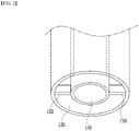
- Fig. 2 is an enlarged view of the lower part of the flow path included in the secondary battery of Fig. 1 .
- a secondary battery 100 includes a jelly roll electrode assembly 110 in which a cathode sheet, an anode sheet, and a separator interposed between the cathode sheet and the anode sheet are wound together, and a battery case 120 to which the jelly roll electrode assembly 110 is mounted.
- the battery case 120 is configured such that flow paths 130 and 140 recessed toward the center of the jelly roll electrode assembly 110 are formed in the lower part of the battery case 120.
- the secondary battery 100 according to the present embodiment is configured such that the flow paths 130 and 140 are formed in the lower part of the battery case 120 and thus, the fluid flowing into and moving to the flow paths 130 and 140 can absorb heat generated in the center of the jelly roll electrode assembly 110. Thereby, the secondary battery 100 according to the present embodiment can improve the cooling performance.
- the flow paths 130 and 140 include a first flow path 130 and a second flow path 140 located at the center of the first flow path 130.
- the upper part of the second flow path 140 is opened toward the upper part of the first flow path 130.
- the fluid flowing into or flowing out to the first flow path 130 from the second flow path 140 may move in all directions toward the upper part of the first flow path 130.
- first flow path 130 and the second flow path 140 allow the fluid to move through their respective upper parts.
- the fluid flowing into the second flow path 140 moves to the upper part of the second flow path 140 and flows into the upper part of the first flow path 130.
- the fluid flowing into the upper part of the first flow path 130 may move toward the lower part of the first flow path 130.
- the fluid flowing into the first flow path 130 moves to the upper part of the first flow path 130 and flows into the upper part of the second flow path 140.
- the fluid flowing into the upper part of the second flow path 140 may move toward the lower part of the first flow path 130.
- the flow paths 130 and 140 include the first flow path 130 and the second flow path 140, and the fluid flowing into the flow paths 130 and 140 can sequentially move through the first flow path 130 and the second flow path 140, so that the movement path of the fluid can be formed long. Further, the long-formed fluid movement path can increase the time during which the fluid flows into the flow paths 130 and 140. Further, the cooling performance of the jelly roll electrode assembly 110 can be improved.
- the flow paths 130 and 140 allow the fluid to move through the upper parts of the first flow path 130 and the second flow path 140, respectively, so that a movement path formed by the first flow path 130 and the second flow path 140 may be formed longer. Further, cooling can be easily performed not only at the center of the jelly roll electrode assembly 110 adjacent to the outer surface of the battery case, but also at the upper end of the center of the jelly roll electrode assembly 110.
- the diameters of the first flow path 130 and the second flow path 140 may be smaller than the diameter of the center of the jelly roll electrode assembly 110.
- the diameter of the first flow path 130 is smaller than the diameter of the center of the jelly roll electrode assembly 110, wherein the diameter of the second flow path 140 may be smaller than a diameter of the first flow path 130.
- the height of the first flow path 130 and the second flow path 140 may be smaller than the height of the jelly roll electrode assembly 110.
- the height of the first flow path 130 is smaller than the height of the jelly roll electrode assembly 110, wherein the height of the second flow path 140 may be smaller than the height of the first flow path 130.
- the secondary battery 100 may be configured such that at least two connection parts 150 are located between the first flow path 130 and the second flow path 140. Also, the connection parts 150 may be extended from a lower part to an upper part of the first flow path 130 or the second flow path 140.
- connection part 150 can fix the second flow path 140 to the first flow path 130 without interfering with the fluid flowing into or moving to the first flow path 130 and the second flow path 140.
- connection part 150 can be formed of a material such as a cooling fin.
- the material of the connection part 150 is not limited to the cooling fin, and any member having high thermal conductivity can be included in the present embodiment.
- connection part 150 can increase the movement time of the fluid moving along the connection part 150 in addition to the effect of fixing the first flow path 130 and the second flow path 140 to each other, and thus the cooling performance can also be further improved.
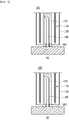
- Fig. 3 is a diagram showing a structure in which an external nozzle is coupled to the secondary battery of Fig. 1 .
- a nozzle 200 may be connected to the lower part of the second flow path 140.
- the nozzle 200 can apply a positive pressure or a negative pressure to the inside of the second flow path 140.
- the nozzle 150 when the nozzle 150 is connected to the flow paths 130 and 140 and a positive or negative pressure is applied, the fluid in the inside of the flow paths 130 and 140 may move through a movement path formed by the first flow path 130 and the second flow path 140. Thereby, cooling of the center of the jelly roll electrode assembly 110 located adjacent to the flow paths 130 and 140 can be smoothly performed, and the cooling performance can be further improved by the pressure applied from the nozzle 150.
- Figs. 4 and 5 are partial cross-sectional views of a secondary battery according to another embodiment of the present disclosure.
- a protrusion 135 may be formed in at least any one of the first flow path 130 and the second flow path 140.
- the protrusion 135 may be formed on the first flow path 130.
- the protrusion 135 may be formed on the first flow path 130 and may be protruded toward the second flow path 140.
- the protrusion 135 is formed on the first flow path 130 adjacent to the jelly roll electrode assembly 110, so that the cooling performance of the jelly roll electrode assembly 110 can be further improved.
- the position of the protrusion 135 is not limited thereto, and can be formed on both the first flow path 130 and the second flow path 14.
- the height of the protrusion 135 may be smaller than the distance between the first flow path 130 and the second flow path 140. Therefore, the first flow path 130 includes the protrusion 135, so that the movement time of the fluid flowing between the first flow path 130 and the second flow path 140 can be lengthened, and the cooling performance can also be improved.
- the protrusion 135 may include at least two protrusions.
- the at least two protrusions may be spaced apart from each other by the same distance. Thereby, in the secondary battery 100 according to the present embodiment, the degree of cooling by the fluid flowing between the first flow path 130 and the second flow path 140 may be uniform.
- the present disclosure is not limited thereto, and the at least two protrusions may be spaced apart asymmetrically or by a non-uniform distance.
- the protrusion 135 includes at least two protrusions, and the protrusions may be formed of cooling fins.
- the secondary battery 100 according to the present embodiment can further improve the cooling performance by the fluid flowing between the first flow path 130 and the second flow path 140.
- the protrusion 135 includes at least two protrusions, and the protrusions may be formed in a linear shape or a semicircular shape. More preferably, the protrusion may have gently formed edges. Thereby, in the secondary battery 100 according to the present embodiment, the fluid flowing between the first flow path 130 and the second flow path 140 can move easily without being stagnated in a specific part.
- Fig. 6 is a cross-sectional view schematically showing a cross section of a flow path included in a secondary battery according to another embodiment of the present disclosure.
- a protrusion 135 extending in the form of a screw may be formed along between the first flow path 130 and the second flow path 140. More specifically, the protrusion 135 may be extended in an oblique direction along between the first flow path 130 and the second flow path 140.
- the length of the protrusion 135 extending along between the first flow path 130 and the second flow path 140 can be maximized, so that the movement time of the fluid flowing between the first flow path 130 and the second flow path 140 can be lengthened. That is, the contact time between the fluid and the first flow path 130 relative to the amount of the injected fluid can be effectively increased, and the cooling performance can also be improved accordingly.
- a protrusion 135 is formed between the first flow path 130 and the second flow path 140, and the protrusion 135 may include at least two rectangular plate-shaped protrusions.
- each of the protrusions may be spaced apart from each other by the same distance.
- the present disclosure is not limited thereto, and each of the protrusions may be spaced apart from each other asymmetrically or by a non-uniform distance.
- the protrusion 135 includes a plate-shaped projection, so that the contact area with the fluid flowing between the first flow path 130 and the second flow path 140 can be increased, and the cooling performance can also be improved accordingly.
- the protrusion 135 is formed on the first flow path 130 adjacent to the jelly roll electrode assembly 110, so that the cooling performance of the jelly roll electrode assembly 110 can be further improved.
- a protrusion 135 is formed between the first flow path 130 and the second flow path 140, and the protrusion 135 may be extended along the first flow path 130. At this time, the protrusion 135 may be located apart from the second flow path 130.
- the protrusion 135 has a shape extending along the first flow path 130, so that the contact area with the fluid flowing between the first flow path 130 and the second flow path 140 can be maximized, and the cooling performance can also be improved accordingly.
- the protrusion 135 is formed on the first flow path 130 adjacent to the jelly roll electrode assembly 110, so that cooling performance for the jelly roll electrode assembly 110 can be further improved.
- the above-mentioned secondary battery can be applied to various devices.
- a device can be applied to a vehicle means such as an electric bicycle, an electric vehicle, or a hybrid vehicle, but the present disclosure is not limited thereto, and is applicable to various devices that can use a secondary battery.
Landscapes
- Chemical & Material Sciences (AREA)
- Chemical Kinetics & Catalysis (AREA)
- Electrochemistry (AREA)
- General Chemical & Material Sciences (AREA)
- Engineering & Computer Science (AREA)
- Manufacturing & Machinery (AREA)
- Secondary Cells (AREA)
- Sealing Battery Cases Or Jackets (AREA)
Abstract
Description
- This application claims the benefit of
Korean Patent Application No. 10-2020-0128637 filed on October 6, 2020 Korean Patent Application No. 10-2021-0131694 filed on October 5, 2021 - The present disclosure relates to a secondary battery and a device including the same, and more particularly to a secondary battery having improved cooling performance and a device including the same.
- Along with the increase of technology development and demands for mobile devices, the demand for batteries as energy sources is increasing rapidly. In particular, a secondary battery has attracted considerable attention as an energy source for power-driven devices, such as an electric bicycle, an electric vehicle, and a hybrid electric vehicle, as well as an energy source for mobile devices, such as a mobile phone, a digital camera, a laptop computer and a wearable device.
- Based on the shape of a battery case, such a secondary battery is classified into a cylindrical battery where an electrode assembly is built in a cylindrical metal can, a prismatic battery where an electrode assembly is built in a prismatic metal can, and a pouch type battery where an electrode assembly is built in a pouch type case formed of an aluminum laminate sheet. Among them, the cylindrical battery has an advantage of having a relatively large capacity and being structurally stable.
- Particularly, in the case of a large-capacity secondary battery requiring high output, as the diameter and/or size of the battery increases, the thickness increases. With the conventional external cooling method, it may be difficult to perform sufficient cooling inside the secondary battery. Further, uniform cooling inside the secondary battery is impossible. In addition, the conventional external cooling method may form an excessive temperature gradient inside the secondary battery, and thus deviations may occur in the performance and deterioration of the secondary battery, and the risk of fire due to lithium deposition or overheating may also exist. Therefore, there is a need to develop a secondary battery having improved cooling performance in consideration of the large capacity of the secondary battery.
- It is an object of the present disclosure to provide a secondary battery having improved cooling performance and a device including the same.
- The objects of the present disclosure are not limited to the aforementioned objects, and other objects which are not described herein should be clearly understood by those skilled in the art from the following detailed description and the accompanying drawings.
- According to one aspect of the present disclosure, there is provided a secondary battery secondary battery comprising: a jelly roll electrode assembly in which a cathode sheet, an anode sheet, and a separator interposed between the cathode sheet and the anode sheet are wound together; and a battery case to which the jelly roll electrode assembly is mounted, wherein the battery case is configured such that a flow path recessed toward the center of the jelly roll electrode assembly is formed in the lower part of the battery case, wherein the flow path comprises a first flow path and a second flow path located in the center of the first flow path, and wherein an upper part of the second flow path is opened toward the upper part of the first flow path.
- A protrusion may be formed in at least any one of the first flow path and the second flow path.
- The protrusion may be formed on the first flow path.
- The protrusion may include at least two protrusions.
- The protrusion may be formed of a cooling fin.
- The at least two protrusions may be spaced apart from each other by the same distance.
- The protrusions may be formed in a linear shape or a semicircular shape.
- A diameter of the first flow path may be smaller than a diameter of a center of the jelly roll electrode assembly.
- A height of the first flow path and the second flow path may be smaller than a height of the jelly roll electrode assembly.
- A nozzle may be connected to the lower part of the second flow path, and a positive or negative pressure may be applied from the nozzle to the inside of the second flow path.
- At least two connection parts may be located between the first flow path and the second flow path.
- The connection part may be extended from a lower part to an upper part of the first flow path or the second flow path.
- According to another aspect of the present disclosure, there is provided a device comprising the above-mentioned secondary battery.
- According to embodiments, the secondary battery of the present disclosure and a device including the same can improve the cooling performance.
- The effects of the present disclosure are not limited to the effects mentioned above and additional other effects not described above will be clearly understood from the detailed description and the appended drawings by those skilled in the art.
-
-
Fig. 1 is a partial cross-sectional view of a secondary battery according to an embodiment of the present disclosure; -
Fig. 2 is an enlarged view of the lower part of the flow path included in the secondary battery ofFig. 1 ; -
Fig. 3 is a diagram showing a structure in which an external nozzle is coupled to the secondary battery ofFig. 1 ; -
Figs. 4 and5 are partial cross-sectional views of a secondary battery according to another embodiment of the present disclosure; and -
Fig. 6 is a cross-sectional view schematically showing a cross section of a flow path included in a secondary battery according to another embodiment of the present disclosure. - Hereinafter, various embodiments of the present disclosure will be described in detail with reference to the accompanying drawings so that those skilled in the art can easily carry out them. The present disclosure may be modified in various different ways, and is not limited to the embodiments set forth herein.
- Portions that are irrelevant to the description will be omitted to clearly describe the present disclosure, and like reference numerals designate like elements throughout the specification.
- Further, in the drawings, the size and thickness of each element are arbitrarily illustrated for convenience of description, and the present disclosure is not necessarily limited to those illustrated in the drawings. In the drawings, the thickness of layers, regions, etc. are exaggerated for clarity. In the drawings, for convenience of description, the thicknesses of some layers and regions are exaggerated.
- Further, throughout the specification, when a portion is referred to as "including" a certain component, it means that the portion can further include other components, without excluding the other components, unless otherwise stated.
- Further, throughout the specification, when referred to as "planar", it means when a target portion is viewed from the upper side, and when referred to as "cross-sectional", it means when a target portion is viewed from the side of a cross section cut vertically.
- Now, the secondary battery according to an embodiment of the present disclosure will be described. However, the secondary battery herein is not limited to a cylindrical battery, and secondary batteries having various shapes may be described with identical or similar contents.
-
Fig. 1 is a partial cross-sectional view of a secondary battery according to an embodiment of the present disclosure.Fig. 2 is an enlarged view of the lower part of the flow path included in the secondary battery ofFig. 1 . - Referring to
Fig. 1 , asecondary battery 100 according to an embodiment of the present disclosure includes a jellyroll electrode assembly 110 in which a cathode sheet, an anode sheet, and a separator interposed between the cathode sheet and the anode sheet are wound together, and abattery case 120 to which the jellyroll electrode assembly 110 is mounted. Here, thebattery case 120 is configured such thatflow paths roll electrode assembly 110 are formed in the lower part of thebattery case 120. - Thereby, the
secondary battery 100 according to the present embodiment is configured such that theflow paths battery case 120 and thus, the fluid flowing into and moving to theflow paths roll electrode assembly 110. Thereby, thesecondary battery 100 according to the present embodiment can improve the cooling performance. - The
flow paths first flow path 130 and asecond flow path 140 located at the center of thefirst flow path 130. Here, the upper part of thesecond flow path 140 is opened toward the upper part of thefirst flow path 130. Thereby, the fluid flowing into or flowing out to thefirst flow path 130 from thesecond flow path 140 may move in all directions toward the upper part of thefirst flow path 130. - Further, the
first flow path 130 and thesecond flow path 140 allow the fluid to move through their respective upper parts. In one example, the fluid flowing into thesecond flow path 140 moves to the upper part of thesecond flow path 140 and flows into the upper part of thefirst flow path 130. The fluid flowing into the upper part of thefirst flow path 130 may move toward the lower part of thefirst flow path 130. On the contrary, the fluid flowing into thefirst flow path 130 moves to the upper part of thefirst flow path 130 and flows into the upper part of thesecond flow path 140. The fluid flowing into the upper part of thesecond flow path 140 may move toward the lower part of thefirst flow path 130. - Thereby, the
flow paths first flow path 130 and thesecond flow path 140, and the fluid flowing into theflow paths first flow path 130 and thesecond flow path 140, so that the movement path of the fluid can be formed long. Further, the long-formed fluid movement path can increase the time during which the fluid flows into theflow paths roll electrode assembly 110 can be improved. - In addition, the
flow paths first flow path 130 and thesecond flow path 140, respectively, so that a movement path formed by thefirst flow path 130 and thesecond flow path 140 may be formed longer. Further, cooling can be easily performed not only at the center of the jellyroll electrode assembly 110 adjacent to the outer surface of the battery case, but also at the upper end of the center of the jellyroll electrode assembly 110. - Referring to
Figs. 1 and2 , the diameters of thefirst flow path 130 and thesecond flow path 140 may be smaller than the diameter of the center of the jellyroll electrode assembly 110. In particular, the diameter of thefirst flow path 130 is smaller than the diameter of the center of the jellyroll electrode assembly 110, wherein the diameter of thesecond flow path 140 may be smaller than a diameter of thefirst flow path 130. Further, the height of thefirst flow path 130 and thesecond flow path 140 may be smaller than the height of the jellyroll electrode assembly 110. In particular, the height of thefirst flow path 130 is smaller than the height of the jellyroll electrode assembly 110, wherein the height of thesecond flow path 140 may be smaller than the height of thefirst flow path 130. - Referring to
Figs. 1 and2 , thesecondary battery 100 according to the present embodiment may be configured such that at least twoconnection parts 150 are located between thefirst flow path 130 and thesecond flow path 140. Also, theconnection parts 150 may be extended from a lower part to an upper part of thefirst flow path 130 or thesecond flow path 140. - Thereby, the
connection part 150 can fix thesecond flow path 140 to thefirst flow path 130 without interfering with the fluid flowing into or moving to thefirst flow path 130 and thesecond flow path 140. - As an example, the
connection part 150 can be formed of a material such as a cooling fin. However, the material of theconnection part 150 is not limited to the cooling fin, and any member having high thermal conductivity can be included in the present embodiment. - Therefore, the
connection part 150 can increase the movement time of the fluid moving along theconnection part 150 in addition to the effect of fixing thefirst flow path 130 and thesecond flow path 140 to each other, and thus the cooling performance can also be further improved. -
Fig. 3 is a diagram showing a structure in which an external nozzle is coupled to the secondary battery ofFig. 1 . Referring toFig. 3 , in thesecondary battery 100 according to the present embodiment, anozzle 200 may be connected to the lower part of thesecond flow path 140. Here, thenozzle 200 can apply a positive pressure or a negative pressure to the inside of thesecond flow path 140. - Referring to
Fig. 3(a) , when thenozzle 200 applies a negative pressure to the inside of thesecond flow path 140, the fluid in the inside of thesecond flow path 140 moves to the lower part of thesecond flow path 140 by thenozzle 200, and the fluid in the upper part of thefirst flow path 130 fills the upper part of thesecond flow path 140. Thereby, the fluid in the lower part of thefirst flow path 130 also moves to the upper part of thefirst flow path 130, and the lower part of thefirst flow path 130 allows the external fluid to move to the inside of the first flow path. - Similarly, referring to
Fig. 3(b) , when thenozzle 200 applies a positive pressure to the inside of thesecond flow path 140, the fluid in the inside of thesecond flow path 140 moves to the upper part of thesecond flow path 140 by thenozzle 200, and the fluid in the inside of thefirst flow path 130 moves to the lower part of thefirst flow path 140. Thereby, the fluid in the lower part of thefirst flow path 130 moves to the outside. - Therefore, in the
secondary battery 100 according to the present embodiment, when thenozzle 150 is connected to theflow paths flow paths first flow path 130 and thesecond flow path 140. Thereby, cooling of the center of the jellyroll electrode assembly 110 located adjacent to theflow paths nozzle 150. -
Figs. 4 and5 are partial cross-sectional views of a secondary battery according to another embodiment of the present disclosure. - Referring to
Figs. 4 and5 , aprotrusion 135 may be formed in at least any one of thefirst flow path 130 and thesecond flow path 140. - As an example, the
protrusion 135 may be formed on thefirst flow path 130. Here, theprotrusion 135 may be formed on thefirst flow path 130 and may be protruded toward thesecond flow path 140. Thus, theprotrusion 135 is formed on thefirst flow path 130 adjacent to the jellyroll electrode assembly 110, so that the cooling performance of the jellyroll electrode assembly 110 can be further improved. - However, the position of the
protrusion 135 is not limited thereto, and can be formed on both thefirst flow path 130 and the second flow path 14. - More specifically, the height of the
protrusion 135 may be smaller than the distance between thefirst flow path 130 and thesecond flow path 140. Therefore, thefirst flow path 130 includes theprotrusion 135, so that the movement time of the fluid flowing between thefirst flow path 130 and thesecond flow path 140 can be lengthened, and the cooling performance can also be improved. - Further, the
protrusion 135 may include at least two protrusions. The at least two protrusions may be spaced apart from each other by the same distance. Thereby, in thesecondary battery 100 according to the present embodiment, the degree of cooling by the fluid flowing between thefirst flow path 130 and thesecond flow path 140 may be uniform. However, the present disclosure is not limited thereto, and the at least two protrusions may be spaced apart asymmetrically or by a non-uniform distance. - Further, the
protrusion 135 includes at least two protrusions, and the protrusions may be formed of cooling fins. Thereby, thesecondary battery 100 according to the present embodiment can further improve the cooling performance by the fluid flowing between thefirst flow path 130 and thesecond flow path 140. - Further, referring to
Figs. 4 and5 , theprotrusion 135 includes at least two protrusions, and the protrusions may be formed in a linear shape or a semicircular shape. More preferably, the protrusion may have gently formed edges. Thereby, in thesecondary battery 100 according to the present embodiment, the fluid flowing between thefirst flow path 130 and thesecond flow path 140 can move easily without being stagnated in a specific part. -
Fig. 6 is a cross-sectional view schematically showing a cross section of a flow path included in a secondary battery according to another embodiment of the present disclosure. - Referring to
Fig. 6(a) , in the secondary battery according to the present embodiment, aprotrusion 135 extending in the form of a screw may be formed along between thefirst flow path 130 and thesecond flow path 140. More specifically, theprotrusion 135 may be extended in an oblique direction along between thefirst flow path 130 and thesecond flow path 140. - Thereby, the length of the
protrusion 135 extending along between thefirst flow path 130 and thesecond flow path 140 can be maximized, so that the movement time of the fluid flowing between thefirst flow path 130 and thesecond flow path 140 can be lengthened. That is, the contact time between the fluid and thefirst flow path 130 relative to the amount of the injected fluid can be effectively increased, and the cooling performance can also be improved accordingly. - Referring to
Fig. 6(b) , in the secondary battery according to the present embodiment, aprotrusion 135 is formed between thefirst flow path 130 and thesecond flow path 140, and theprotrusion 135 may include at least two rectangular plate-shaped protrusions. At this time, similarly toFigs. 4 and5 , each of the protrusions may be spaced apart from each other by the same distance. However, the present disclosure is not limited thereto, and each of the protrusions may be spaced apart from each other asymmetrically or by a non-uniform distance. - Thereby, the
protrusion 135 includes a plate-shaped projection, so that the contact area with the fluid flowing between thefirst flow path 130 and thesecond flow path 140 can be increased, and the cooling performance can also be improved accordingly. In addition, theprotrusion 135 is formed on thefirst flow path 130 adjacent to the jellyroll electrode assembly 110, so that the cooling performance of the jellyroll electrode assembly 110 can be further improved. - Referring to
Fig. 6(c) , in the secondary battery according to the present embodiment, aprotrusion 135 is formed between thefirst flow path 130 and thesecond flow path 140, and theprotrusion 135 may be extended along thefirst flow path 130. At this time, theprotrusion 135 may be located apart from thesecond flow path 130. - Thereby, the
protrusion 135 has a shape extending along thefirst flow path 130, so that the contact area with the fluid flowing between thefirst flow path 130 and thesecond flow path 140 can be maximized, and the cooling performance can also be improved accordingly. In addition, theprotrusion 135 is formed on thefirst flow path 130 adjacent to the jellyroll electrode assembly 110, so that cooling performance for the jellyroll electrode assembly 110 can be further improved. - The above-mentioned secondary battery can be applied to various devices. Such a device can be applied to a vehicle means such as an electric bicycle, an electric vehicle, or a hybrid vehicle, but the present disclosure is not limited thereto, and is applicable to various devices that can use a secondary battery.
- Although preferred embodiments of the present disclosure have been described in detail above, the scope of the present disclosure is not limited thereto, and various modifications and improvements can be made by those skilled in the art using the basic concepts of the present disclosure defined in the appended claims, which also falls under the scope of the present disclosure.
-
- 100: secondary battery
- 110: jelly roll electrode assembly
- 120: battery case
- 130: first flow path
- 140: second flow path
- 150: connection part
- 200: nozzle
Claims (13)
- A secondary battery comprising:a jelly roll electrode assembly in which a cathode sheet, an anode sheet, and a separator interposed between the cathode sheet and the anode sheet are wound together; anda battery case to which the jelly roll electrode assembly is mounted,wherein the battery case is configured such that a flow path recessed toward the center of the jelly roll electrode assembly is formed in the lower part of the battery case,wherein the flow path comprises a first flow path and a second flow path located in the center of the first flow path, andwherein an upper part of the second flow path is opened toward the upper part of the first flow path.
- The secondary battery of claim 1, wherein:
a protrusion is formed in at least any one of the first flow path and the second flow path. - The secondary battery of claim 2, wherein:
the protrusion is formed on the first flow path. - The secondary battery of claim 3, wherein:
the protrusion comprises at least two protrusions. - The secondary battery of claim 4, wherein:
the protrusion is formed of a cooling fin. - The secondary battery of claim 4, wherein:
the at least two protrusions are spaced apart from each other by the same distance. - The secondary battery of claim 4, wherein:
the protrusions are formed in a linear shape or a semicircular shape. - The secondary battery of claim 1, wherein:
a diameter of the first flow path is smaller than a diameter of a center of the jelly roll electrode assembly. - The secondary battery of claim 8, wherein:
a height of the first flow path and the second flow path is smaller than a height of the jelly roll electrode assembly. - The secondary battery of claim 1, wherein:a nozzle is connected to the lower part of the second flow path, anda positive or negative pressure is applied from the nozzle to the inside of the second flow path.
- The secondary battery of claim 1, wherein:
at least two connection parts are located between the first flow path and the second flow path. - The secondary battery of claim 11, wherein:
the connection part is extended from a lower part to an upper part of the first flow path or the second flow path. - A device comprising the secondary battery as set forth in claim 1.
Applications Claiming Priority (3)
| Application Number | Priority Date | Filing Date | Title |
|---|---|---|---|
| KR20200128637 | 2020-10-06 | ||
| KR1020210131694A KR20220045911A (en) | 2020-10-06 | 2021-10-05 | Secondary battery and device including the same |
| PCT/KR2021/013666 WO2022075730A1 (en) | 2020-10-06 | 2021-10-06 | Secondary battery and device including same |
Publications (3)
| Publication Number | Publication Date |
|---|---|
| EP4109631A1 true EP4109631A1 (en) | 2022-12-28 |
| EP4109631A4 EP4109631A4 (en) | 2023-10-18 |
| EP4109631B1 EP4109631B1 (en) | 2025-11-26 |
Family
ID=81126274
Family Applications (1)
| Application Number | Title | Priority Date | Filing Date |
|---|---|---|---|
| EP21877981.7A Active EP4109631B1 (en) | 2020-10-06 | 2021-10-06 | Secondary battery and device including the same |
Country Status (7)
| Country | Link |
|---|---|
| US (1) | US12500319B2 (en) |
| EP (1) | EP4109631B1 (en) |
| JP (1) | JP7404617B2 (en) |
| CN (1) | CN115244762A (en) |
| ES (1) | ES3058904T3 (en) |
| PL (1) | PL4109631T3 (en) |
| WO (1) | WO2022075730A1 (en) |
Cited By (1)
| Publication number | Priority date | Publication date | Assignee | Title |
|---|---|---|---|---|
| EP4571937A1 (en) * | 2023-12-12 | 2025-06-18 | Customcells Holding GmbH | Battery cell with active cooling, intermediate piece, battery cell system and method for manufacturing a battery cell |
Families Citing this family (1)
| Publication number | Priority date | Publication date | Assignee | Title |
|---|---|---|---|---|
| US20240380025A1 (en) * | 2023-05-12 | 2024-11-14 | GM Global Technology Operations LLC | Rechargeable energy storage system including energy storage cells having an internal cooling structure |
Family Cites Families (13)
| Publication number | Priority date | Publication date | Assignee | Title |
|---|---|---|---|---|
| JP2001313078A (en) * | 2000-04-27 | 2001-11-09 | Shin Kobe Electric Mach Co Ltd | Sealed non-aqueous secondary battery and battery pack |
| KR101191664B1 (en) * | 2010-06-24 | 2012-10-17 | 에스비리모티브 주식회사 | Battery module |
| KR20130003390U (en) * | 2010-10-01 | 2013-06-07 | 그라프텍 인터내셔널 홀딩스 인코포레이티드 | Thermal management structures for battery packs |
| JP2012174344A (en) | 2011-02-17 | 2012-09-10 | Hitachi Ltd | Battery and manufacturing method therefor |
| KR101315672B1 (en) | 2012-07-06 | 2013-10-08 | (주)오렌지파워 | Electrode assembly, battery having the same and method of fabricating battery |
| GB2532724B (en) * | 2014-11-24 | 2017-11-01 | Jaguar Land Rover Ltd | Rechargeable battery and cooling system therefor |
| KR102067643B1 (en) * | 2015-07-06 | 2020-01-17 | 주식회사 엘지화학 | Battery Cell Having Coolant Flow Conduit |
| CN205016641U (en) * | 2015-09-24 | 2016-02-03 | 青勇 | Battery case , battery and battery module |
| CN205016640U (en) * | 2015-09-24 | 2016-02-03 | 青勇 | Battery case , battery and battery module |
| KR102072762B1 (en) | 2015-12-14 | 2020-02-03 | 주식회사 엘지화학 | Can Type Secondary Battery and Secondary Battery Module including the same |
| FR3075478B1 (en) * | 2017-12-14 | 2019-12-13 | Commissariat A L'energie Atomique Et Aux Energies Alternatives | SUB-ASSEMBLY INCLUDING A HOLLOW CHUCK AND A PART OF A HOLLOW CROSS-FORMING TERMINAL FOR A METAL-ION ELECTROCHEMICAL ACCUMULATOR, ASSOCIATED ACCUMULATOR |
| KR102028330B1 (en) * | 2017-12-20 | 2019-10-04 | 주식회사 성우하이텍 | Secondary battery module |
| DE102019001520B3 (en) * | 2019-03-04 | 2020-02-06 | Friedrich Grimm | ACCUMULATOR CELL AS A TUBE CELL AND AS A HEAT EXCHANGER, ELECTRIC VEHICLE WITH A TUBE CELL |
-
2021
- 2021-10-06 CN CN202180020433.1A patent/CN115244762A/en active Pending
- 2021-10-06 WO PCT/KR2021/013666 patent/WO2022075730A1/en not_active Ceased
- 2021-10-06 ES ES21877981T patent/ES3058904T3/en active Active
- 2021-10-06 JP JP2022552320A patent/JP7404617B2/en active Active
- 2021-10-06 EP EP21877981.7A patent/EP4109631B1/en active Active
- 2021-10-06 US US17/913,347 patent/US12500319B2/en active Active
- 2021-10-06 PL PL21877981.7T patent/PL4109631T3/en unknown
Cited By (1)
| Publication number | Priority date | Publication date | Assignee | Title |
|---|---|---|---|---|
| EP4571937A1 (en) * | 2023-12-12 | 2025-06-18 | Customcells Holding GmbH | Battery cell with active cooling, intermediate piece, battery cell system and method for manufacturing a battery cell |
Also Published As
| Publication number | Publication date |
|---|---|
| ES3058904T3 (en) | 2026-03-13 |
| EP4109631A4 (en) | 2023-10-18 |
| JP2023521942A (en) | 2023-05-26 |
| EP4109631B1 (en) | 2025-11-26 |
| WO2022075730A1 (en) | 2022-04-14 |
| US20230155264A1 (en) | 2023-05-18 |
| CN115244762A (en) | 2022-10-25 |
| PL4109631T3 (en) | 2026-03-16 |
| US12500319B2 (en) | 2025-12-16 |
| JP7404617B2 (en) | 2023-12-26 |
Similar Documents
| Publication | Publication Date | Title |
|---|---|---|
| US11935997B2 (en) | Pouch exterior for secondary battery, pouch-type secondary battery using the pouch exterior, and method of manufacturing the pouch-type secondary battery | |
| JP7027641B2 (en) | A cooling jacket with a non-uniform flow path for cooling the surface of the battery cell and a battery module containing it. | |
| JP5526227B2 (en) | Cell cartridge having elastic pressing member, and cell module including cell cartridge | |
| KR101233318B1 (en) | Battery module | |
| CN106328844B (en) | Rechargeable Battery Module | |
| KR101784743B1 (en) | Rechargeable battery | |
| EP3852185A1 (en) | Power supply device | |
| KR102025861B1 (en) | Cooling Apparatus for Battery Cell | |
| JP7442920B2 (en) | Battery module and battery pack containing it | |
| US10396336B2 (en) | Secondary battery | |
| US20210203020A1 (en) | Battery Module, and Battery Pack Including the Same | |
| EP4199191B1 (en) | Battery module and battery pack comprising same | |
| US12500319B2 (en) | Secondary battery and device including the same | |
| JP2022551880A (en) | Battery module and battery pack containing same | |
| JP2023554628A (en) | Battery module and battery pack containing it | |
| JP2023537017A (en) | Battery module and battery pack containing same | |
| KR20220076835A (en) | Secondary battery and device including the same | |
| US12519162B2 (en) | Battery cell and method of manufacturing the same | |
| KR102663793B1 (en) | Battery module and method of manufacturing the same | |
| KR102188064B1 (en) | Secondary battery module and method for fabricating the same | |
| KR20220045911A (en) | Secondary battery and device including the same | |
| JP5812956B2 (en) | Constituent body of prismatic battery, its assembled battery, and cooling device | |
| KR20230084757A (en) | Cooling fin, battery module and battery pack including the same | |
| US20250300272A1 (en) | Battery module with improved cooling structure and battery pack including the same | |
| US20240154206A1 (en) | Cooling fin, battery module, battery pack and device including the same |
Legal Events
| Date | Code | Title | Description |
|---|---|---|---|
| STAA | Information on the status of an ep patent application or granted ep patent |
Free format text: STATUS: THE INTERNATIONAL PUBLICATION HAS BEEN MADE |
|
| PUAI | Public reference made under article 153(3) epc to a published international application that has entered the european phase |
Free format text: ORIGINAL CODE: 0009012 |
|
| STAA | Information on the status of an ep patent application or granted ep patent |
Free format text: STATUS: REQUEST FOR EXAMINATION WAS MADE |
|
| 17P | Request for examination filed |
Effective date: 20220922 |
|
| AK | Designated contracting states |
Kind code of ref document: A1 Designated state(s): AL AT BE BG CH CY CZ DE DK EE ES FI FR GB GR HR HU IE IS IT LI LT LU LV MC MK MT NL NO PL PT RO RS SE SI SK SM TR |
|
| A4 | Supplementary search report drawn up and despatched |
Effective date: 20230915 |
|
| RIC1 | Information provided on ipc code assigned before grant |
Ipc: H01M 50/107 20210101ALI20230911BHEP Ipc: H01M 50/102 20210101ALI20230911BHEP Ipc: H01M 10/6554 20140101ALI20230911BHEP Ipc: H01M 10/654 20140101ALI20230911BHEP Ipc: H01M 10/625 20140101ALI20230911BHEP Ipc: H01M 50/10 20210101ALI20230911BHEP Ipc: H01M 10/04 20060101ALI20230911BHEP Ipc: H01M 10/613 20140101ALI20230911BHEP Ipc: H01M 10/6551 20140101ALI20230911BHEP Ipc: H01M 10/6556 20140101ALI20230911BHEP Ipc: H01M 10/643 20140101AFI20230911BHEP |
|
| DAV | Request for validation of the european patent (deleted) | ||
| DAX | Request for extension of the european patent (deleted) | ||
| STAA | Information on the status of an ep patent application or granted ep patent |
Free format text: STATUS: EXAMINATION IS IN PROGRESS |
|
| 17Q | First examination report despatched |
Effective date: 20240604 |
|
| RIC1 | Information provided on ipc code assigned before grant |
Ipc: H01M 50/107 20210101ALI20240524BHEP Ipc: H01M 50/102 20210101ALI20240524BHEP Ipc: H01M 10/6554 20140101ALI20240524BHEP Ipc: H01M 10/654 20140101ALI20240524BHEP Ipc: H01M 10/625 20140101ALI20240524BHEP Ipc: H01M 50/10 20210101ALI20240524BHEP Ipc: H01M 10/04 20060101ALI20240524BHEP Ipc: H01M 10/613 20140101ALI20240524BHEP Ipc: H01M 10/6551 20140101ALI20240524BHEP Ipc: H01M 10/6556 20140101ALI20240524BHEP Ipc: H01M 10/643 20140101AFI20240524BHEP |
|
| GRAP | Despatch of communication of intention to grant a patent |
Free format text: ORIGINAL CODE: EPIDOSNIGR1 |
|
| STAA | Information on the status of an ep patent application or granted ep patent |
Free format text: STATUS: GRANT OF PATENT IS INTENDED |
|
| INTG | Intention to grant announced |
Effective date: 20250623 |
|
| P01 | Opt-out of the competence of the unified patent court (upc) registered |
Free format text: CASE NUMBER: APP_31564/2025 Effective date: 20250701 |
|
| GRAS | Grant fee paid |
Free format text: ORIGINAL CODE: EPIDOSNIGR3 |
|
| GRAA | (expected) grant |
Free format text: ORIGINAL CODE: 0009210 |
|
| STAA | Information on the status of an ep patent application or granted ep patent |
Free format text: STATUS: THE PATENT HAS BEEN GRANTED |
|
| AK | Designated contracting states |
Kind code of ref document: B1 Designated state(s): AL AT BE BG CH CY CZ DE DK EE ES FI FR GB GR HR HU IE IS IT LI LT LU LV MC MK MT NL NO PL PT RO RS SE SI SK SM TR |
|
| REG | Reference to a national code |
Ref country code: CH Ref legal event code: F10 Free format text: ST27 STATUS EVENT CODE: U-0-0-F10-F00 (AS PROVIDED BY THE NATIONAL OFFICE) Effective date: 20251126 Ref country code: GB Ref legal event code: FG4D |
|
| REG | Reference to a national code |
Ref country code: IE Ref legal event code: FG4D |
|
| REG | Reference to a national code |
Ref country code: DE Ref legal event code: R096 Ref document number: 602021043325 Country of ref document: DE |
|
| REG | Reference to a national code |
Ref country code: SE Ref legal event code: TRGR |
|
| REG | Reference to a national code |
Ref country code: ES Ref legal event code: FG2A Ref document number: 3058904 Country of ref document: ES Kind code of ref document: T3 Effective date: 20260313 |
|
| REG | Reference to a national code |
Ref country code: NL Ref legal event code: MP Effective date: 20251126 |
|
| REG | Reference to a national code |
Ref country code: LT Ref legal event code: MG9D |
|
| PG25 | Lapsed in a contracting state [announced via postgrant information from national office to epo] |
Ref country code: NO Free format text: LAPSE BECAUSE OF FAILURE TO SUBMIT A TRANSLATION OF THE DESCRIPTION OR TO PAY THE FEE WITHIN THE PRESCRIBED TIME-LIMIT Effective date: 20260226 |
|
| PG25 | Lapsed in a contracting state [announced via postgrant information from national office to epo] |
Ref country code: HR Free format text: LAPSE BECAUSE OF FAILURE TO SUBMIT A TRANSLATION OF THE DESCRIPTION OR TO PAY THE FEE WITHIN THE PRESCRIBED TIME-LIMIT Effective date: 20251126 Ref country code: AT Free format text: LAPSE BECAUSE OF FAILURE TO SUBMIT A TRANSLATION OF THE DESCRIPTION OR TO PAY THE FEE WITHIN THE PRESCRIBED TIME-LIMIT Effective date: 20251126 Ref country code: FI Free format text: LAPSE BECAUSE OF FAILURE TO SUBMIT A TRANSLATION OF THE DESCRIPTION OR TO PAY THE FEE WITHIN THE PRESCRIBED TIME-LIMIT Effective date: 20251126 |
|
| REG | Reference to a national code |
Ref country code: AT Ref legal event code: MK05 Ref document number: 1862029 Country of ref document: AT Kind code of ref document: T Effective date: 20251126 |
|
| PG25 | Lapsed in a contracting state [announced via postgrant information from national office to epo] |
Ref country code: NL Free format text: LAPSE BECAUSE OF FAILURE TO SUBMIT A TRANSLATION OF THE DESCRIPTION OR TO PAY THE FEE WITHIN THE PRESCRIBED TIME-LIMIT Effective date: 20251126 |
|
| PG25 | Lapsed in a contracting state [announced via postgrant information from national office to epo] |
Ref country code: RS Free format text: LAPSE BECAUSE OF FAILURE TO SUBMIT A TRANSLATION OF THE DESCRIPTION OR TO PAY THE FEE WITHIN THE PRESCRIBED TIME-LIMIT Effective date: 20260226 |
|
| PG25 | Lapsed in a contracting state [announced via postgrant information from national office to epo] |
Ref country code: IS Free format text: LAPSE BECAUSE OF FAILURE TO SUBMIT A TRANSLATION OF THE DESCRIPTION OR TO PAY THE FEE WITHIN THE PRESCRIBED TIME-LIMIT Effective date: 20260326 |
|
| PG25 | Lapsed in a contracting state [announced via postgrant information from national office to epo] |
Ref country code: PT Free format text: LAPSE BECAUSE OF FAILURE TO SUBMIT A TRANSLATION OF THE DESCRIPTION OR TO PAY THE FEE WITHIN THE PRESCRIBED TIME-LIMIT Effective date: 20260326 |
|
| PG25 | Lapsed in a contracting state [announced via postgrant information from national office to epo] |
Ref country code: LV Free format text: LAPSE BECAUSE OF FAILURE TO SUBMIT A TRANSLATION OF THE DESCRIPTION OR TO PAY THE FEE WITHIN THE PRESCRIBED TIME-LIMIT Effective date: 20251126 |
|
| PG25 | Lapsed in a contracting state [announced via postgrant information from national office to epo] |
Ref country code: BG Free format text: LAPSE BECAUSE OF FAILURE TO SUBMIT A TRANSLATION OF THE DESCRIPTION OR TO PAY THE FEE WITHIN THE PRESCRIBED TIME-LIMIT Effective date: 20251126 |