EP4109622A1 - Wound battery - Google Patents
Wound battery Download PDFInfo
- Publication number
- EP4109622A1 EP4109622A1 EP21850342.3A EP21850342A EP4109622A1 EP 4109622 A1 EP4109622 A1 EP 4109622A1 EP 21850342 A EP21850342 A EP 21850342A EP 4109622 A1 EP4109622 A1 EP 4109622A1
- Authority
- EP
- European Patent Office
- Prior art keywords
- wound battery
- positive
- layer
- battery
- negative
- Prior art date
- Legal status (The legal status is an assumption and is not a legal conclusion. Google has not performed a legal analysis and makes no representation as to the accuracy of the status listed.)
- Pending
Links
Images


Classifications
-
- H—ELECTRICITY
- H01—ELECTRIC ELEMENTS
- H01M—PROCESSES OR MEANS, e.g. BATTERIES, FOR THE DIRECT CONVERSION OF CHEMICAL ENERGY INTO ELECTRICAL ENERGY
- H01M10/00—Secondary cells; Manufacture thereof
- H01M10/05—Accumulators with non-aqueous electrolyte
- H01M10/058—Construction or manufacture
- H01M10/0587—Construction or manufacture of accumulators having only wound construction elements, i.e. wound positive electrodes, wound negative electrodes and wound separators
-
- H—ELECTRICITY
- H01—ELECTRIC ELEMENTS
- H01M—PROCESSES OR MEANS, e.g. BATTERIES, FOR THE DIRECT CONVERSION OF CHEMICAL ENERGY INTO ELECTRICAL ENERGY
- H01M10/00—Secondary cells; Manufacture thereof
- H01M10/04—Construction or manufacture in general
- H01M10/0413—Large-sized flat cells or batteries for motive or stationary systems with plate-like electrodes
- H01M10/0418—Large-sized flat cells or batteries for motive or stationary systems with plate-like electrodes with bipolar electrodes
-
- H—ELECTRICITY
- H01—ELECTRIC ELEMENTS
- H01M—PROCESSES OR MEANS, e.g. BATTERIES, FOR THE DIRECT CONVERSION OF CHEMICAL ENERGY INTO ELECTRICAL ENERGY
- H01M10/00—Secondary cells; Manufacture thereof
- H01M10/04—Construction or manufacture in general
- H01M10/0431—Cells with wound or folded electrodes
-
- H—ELECTRICITY
- H01—ELECTRIC ELEMENTS
- H01M—PROCESSES OR MEANS, e.g. BATTERIES, FOR THE DIRECT CONVERSION OF CHEMICAL ENERGY INTO ELECTRICAL ENERGY
- H01M10/00—Secondary cells; Manufacture thereof
- H01M10/05—Accumulators with non-aqueous electrolyte
- H01M10/052—Li-accumulators
- H01M10/0525—Rocking-chair batteries, i.e. batteries with lithium insertion or intercalation in both electrodes; Lithium-ion batteries
-
- H—ELECTRICITY
- H01—ELECTRIC ELEMENTS
- H01M—PROCESSES OR MEANS, e.g. BATTERIES, FOR THE DIRECT CONVERSION OF CHEMICAL ENERGY INTO ELECTRICAL ENERGY
- H01M4/00—Electrodes
- H01M4/02—Electrodes composed of, or comprising, active material
- H01M4/36—Selection of substances as active materials, active masses, active liquids
- H01M4/58—Selection of substances as active materials, active masses, active liquids of inorganic compounds other than oxides or hydroxides, e.g. sulfides, selenides, tellurides, halogenides or LiCoFy; of polyanionic structures, e.g. phosphates, silicates or borates
-
- H—ELECTRICITY
- H01—ELECTRIC ELEMENTS
- H01M—PROCESSES OR MEANS, e.g. BATTERIES, FOR THE DIRECT CONVERSION OF CHEMICAL ENERGY INTO ELECTRICAL ENERGY
- H01M4/00—Electrodes
- H01M4/02—Electrodes composed of, or comprising, active material
- H01M4/36—Selection of substances as active materials, active masses, active liquids
- H01M4/58—Selection of substances as active materials, active masses, active liquids of inorganic compounds other than oxides or hydroxides, e.g. sulfides, selenides, tellurides, halogenides or LiCoFy; of polyanionic structures, e.g. phosphates, silicates or borates
- H01M4/583—Carbonaceous material, e.g. graphite-intercalation compounds or CFx
- H01M4/587—Carbonaceous material, e.g. graphite-intercalation compounds or CFx for inserting or intercalating light metals
-
- H—ELECTRICITY
- H01—ELECTRIC ELEMENTS
- H01M—PROCESSES OR MEANS, e.g. BATTERIES, FOR THE DIRECT CONVERSION OF CHEMICAL ENERGY INTO ELECTRICAL ENERGY
- H01M4/00—Electrodes
- H01M4/02—Electrodes composed of, or comprising, active material
- H01M4/64—Carriers or collectors
- H01M4/66—Selection of materials
- H01M4/665—Composites
- H01M4/667—Composites in the form of layers, e.g. coatings
-
- H—ELECTRICITY
- H01—ELECTRIC ELEMENTS
- H01M—PROCESSES OR MEANS, e.g. BATTERIES, FOR THE DIRECT CONVERSION OF CHEMICAL ENERGY INTO ELECTRICAL ENERGY
- H01M4/00—Electrodes
- H01M4/02—Electrodes composed of, or comprising, active material
- H01M4/64—Carriers or collectors
- H01M4/66—Selection of materials
- H01M4/668—Composites of electroconductive material and synthetic resins
-
- H—ELECTRICITY
- H01—ELECTRIC ELEMENTS
- H01M—PROCESSES OR MEANS, e.g. BATTERIES, FOR THE DIRECT CONVERSION OF CHEMICAL ENERGY INTO ELECTRICAL ENERGY
- H01M50/00—Constructional details or processes of manufacture of the non-active parts of electrochemical cells other than fuel cells, e.g. hybrid cells
- H01M50/10—Primary casings; Jackets or wrappings
- H01M50/131—Primary casings; Jackets or wrappings characterised by physical properties, e.g. gas permeability, size or heat resistance
- H01M50/136—Flexibility or foldability
-
- H—ELECTRICITY
- H01—ELECTRIC ELEMENTS
- H01M—PROCESSES OR MEANS, e.g. BATTERIES, FOR THE DIRECT CONVERSION OF CHEMICAL ENERGY INTO ELECTRICAL ENERGY
- H01M50/00—Constructional details or processes of manufacture of the non-active parts of electrochemical cells other than fuel cells, e.g. hybrid cells
- H01M50/40—Separators; Membranes; Diaphragms; Spacing elements inside cells
- H01M50/409—Separators, membranes or diaphragms characterised by the material
- H01M50/411—Organic material
-
- Y—GENERAL TAGGING OF NEW TECHNOLOGICAL DEVELOPMENTS; GENERAL TAGGING OF CROSS-SECTIONAL TECHNOLOGIES SPANNING OVER SEVERAL SECTIONS OF THE IPC; TECHNICAL SUBJECTS COVERED BY FORMER USPC CROSS-REFERENCE ART COLLECTIONS [XRACs] AND DIGESTS
- Y02—TECHNOLOGIES OR APPLICATIONS FOR MITIGATION OR ADAPTATION AGAINST CLIMATE CHANGE
- Y02E—REDUCTION OF GREENHOUSE GAS [GHG] EMISSIONS, RELATED TO ENERGY GENERATION, TRANSMISSION OR DISTRIBUTION
- Y02E60/00—Enabling technologies; Technologies with a potential or indirect contribution to GHG emissions mitigation
- Y02E60/10—Energy storage using batteries
-
- Y—GENERAL TAGGING OF NEW TECHNOLOGICAL DEVELOPMENTS; GENERAL TAGGING OF CROSS-SECTIONAL TECHNOLOGIES SPANNING OVER SEVERAL SECTIONS OF THE IPC; TECHNICAL SUBJECTS COVERED BY FORMER USPC CROSS-REFERENCE ART COLLECTIONS [XRACs] AND DIGESTS
- Y02—TECHNOLOGIES OR APPLICATIONS FOR MITIGATION OR ADAPTATION AGAINST CLIMATE CHANGE
- Y02P—CLIMATE CHANGE MITIGATION TECHNOLOGIES IN THE PRODUCTION OR PROCESSING OF GOODS
- Y02P70/00—Climate change mitigation technologies in the production process for final industrial or consumer products
- Y02P70/50—Manufacturing or production processes characterised by the final manufactured product
Definitions
- This disclosure relates to the field of batteries, and in particular to a wound battery.
- a wound battery is formed by winding a battery sheet.
- the battery sheet usually includes a separator, and a positive electrode sheet and a negative electrode sheet which are distributed on two sides of the separator.
- an existing wound battery has a relatively large thickness, but space is relatively limited in a usage scenario, such that an energy density is difficult to be further improved.
- a new type of wound battery is provided in the present disclosure to at least improve, or even solve, the above problem of a relatively large thickness of the wound battery and limited increase in energy density due to the relatively large thickness.
- a wound battery formed by winding a battery sheet is provided in implementations of the present disclosure.
- the wound battery can include a separator and a flexible battery sheet with an integrated structure.
- the battery sheet can include a current collector, a positive active layer, and a negative active layer.
- the current collector can have an insulating layer as a substrate, and a positive metal layer and a negative metal layer which are formed on surfaces of two sides of the insulating layer, the positive active layer is formed on a surface of the positive metal layer, and the negative active layer is formed on a surface of the negative metal layer.
- the separator can be laminated on and cover a surface of the positive active layer and/or a surface of the negative active layer, and configured to prevent the positive active layer from directly contacting the negative active layer.
- a positive electrode sheet and a negative electrode sheet are independently fabricated and then a separator is utilized to isolate the two for winding.
- winding tightness of the two is difficult to be improved and alignment and cooperation between layers is difficult to be controlled, such that the existing wound battery has a relatively thick thickness, and therefore is limited by installation space and improvement of an energy density of the existing wound battery is limited.
- the battery sheet with the integrated structure exists in the wound battery as a whole, rather than battery sheets in the existing wound battery being laminated and placed and in contact with each other by an extrusion force.
- the layers are not substantially connected directly or indirectly, but only in laminated contact with each other. Therefore, the layers independently exist in the existing wound battery respectively.
- any two adjacent layers of the battery sheet are substantially in direct contact and connection, such that the battery sheet macroscopically appears as "one layer" in the wound battery.
- the wound battery can be conveniently curled and bent, and a thickness can be significantly reduced, which is beneficial to improving a winding density and improve an energy density.
- the separator extends to an innermost circle of the wound battery (an innermost ring layer among rings formed in the wound battery), and forms an inner circle section or the innermost circle layer.
- the separator may be laminated on and cover the surface of the positive active layer and/or the negative active layer of the innermost circle of the flexible battery sheet.
- the inner circle section (can also be known as an "innermost-circle-layer separator") is double-layer.
- the inner circle section is single-layer.
- the positive metal layer has a first positive exposed section located in a region of the innermost circle and the negative metal layer has a first negative exposed section located in the region of the innermost circle and corresponding to the first positive exposed section.
- the positive metal layer has a second exposed section located in a region of the outermost circle and the negative metal layer has a second negative exposed section located in the region of the outermost circle and corresponding to the second positive exposed section.
- the separator extends to the surface of the positive active layer or the surface of the negative active layer.
- the separator can be laminated on and cover the surface of the positive active layer or the surface of the negative active layer of the flexible battery sheet of the outermost circle.
- the positive active layer may be made of LiFeSO 4 .
- the negative active layer may be made of graphite.
- the positive metal layer may be made of aluminum.
- the negative metal layer may be made of copper.
- Signs 900-existing wound battery; 91-positive electrode sheet; 911-positive active material layer; 912-postive current collector; 92-negative electrode sheet; 921-negative active material layer; 922-negative current collector; 93-separator; 300-wound battery; 100-battery sheet; 101-insulating layer; 102-positive metal layer; 103-nagetive metal layer; 104-positive active layer; 105-negative active layer; 200-current collector; 201-separator.
- wound batteries are widely used in various terminal devices such as electronic devices (e.g., watches, mobile phones, etc.). At present, these devices tend to be highly integrated and miniaturized, therefore, a volume of a wound battery is required to be further reduced. On the other hand, in view of long-term operation of the above electronic devices, an energy density of the wound battery is desired to be sufficiently high to avoid frequent charging.
- electrode materials for example, chooses to use active materials which can provide higher energy densities, such as various ternary materials.
- active materials which can provide higher energy densities, such as various ternary materials.
- electrode materials are difficult to be developed.
- some materials can provide high energy densities, other problems may also be accompanied, for example, short service life, unfriendly environment, difficult fabrication, etc.
- the inventor finds a new path and chooses to improve a structure of a wound battery, so as to avoid a great difficulty in improving active materials.
- a solution proposed by the inventor has indeed improved the aforementioned problems to a certain extent.
- a wound battery with a new type of structure is provided by the inventor.
- the battery can provide a larger winding density, such that under a condition of an identical volume, the battery can provide more power supply space (more bearing space for active materials lead to more carried active materials).
- the wound battery of the present disclosure does not adopt a solution of separating an independently fabricated positive electrode sheet and an independently fabricated negative electrode sheet by a separator and then winding them with an additional separator.
- the wound battery of the present disclosure is fabricated by combining current collectors of the positive electrode sheet and the negative electrode sheet.
- an insulating material is used as a substrate, and then a positive current collector and a negative current collector are fabricated on two sides of the insulating material, such that a current collector with an integrated structure is formed.
- a positive active material and a negative active material are attached to two sides of the current collector respectively (a battery sheet with the integrated structure is formed, and the battery sheet can be made thinner and easier to be curled with a high density), and then a separator is used for winding.
- the wound battery since each electrode sheet is not independently fabricated, an integrated structure is formed.
- the wound battery can be determined to have a two-layer structure, which is a separator layer and an internal energy supply layer respectively.
- the existing wound battery is formed in the form of four layers of winding.
- the thickness of the wound battery of the present disclosure can be effectively reduced, and the high requirement for alignment accuracy is reduced, such that the wound battery can be fabricated with the higher winding density, the higher energy density can be obtained, and accurate alignment of the positive electrode and the negative electrode can be easily realized in use.
- FIG. 1, FIG. 2, and FIG. 3 a structure of an existing wound battery 900 as an improvement basis is provided by the inventor, and has a positive electrode sheet 91, a negative electrode sheet 92, and two separators 93.
- the positive electrode sheet 91 includes a positive current collector 912 and a positive active material layer 911 which is used for a positive electrode and attached to a surface of the positive current collector 912. In addition, as can be seen from FIG. 1 , the positive active material layer 911 wraps the positive current collector 912 inside.
- the negative electrode sheet 92 includes a negative current collector 922 and a negative active material layer 921 which is used for a negative electrode and attached to a surface of the negative current collector 922.
- the negative active material layer 921 wraps the negative current collector 922 inside.
- the wound battery 900 has a four-layer structure, and the positive electrode sheet 91 and the negative electrode sheet 92 are separated by a separator 93. Specifically, when the wound battery 900 is fabricated, a separator 93, the negative electrode sheet 92, a separator 93, and the positive electrode sheet 91 are laminated in sequence. After each lamination is completed, the whole is wound.
- a new wound battery 300 (see FIG. 5 ) is provided by the inventor, and is formed by winding a flexible battery sheet 100 as illustrated in FIG. 4 .
- the wound battery 300 may include the battery sheet 100 and a separator 201.
- the battery sheet 100 may include a current collector 200, a positive active layer 104, and a negative active layer 105. Reference of a winding mode of the battery sheet 100 can be made to FIG. 6 , the positive active layer 104 is in an inner circle layer, and the negative active layer 105 is in an outer circle layer.
- the current collector 200 may be integrated (an integrated structure) and flexible.
- the integrated structure of the current collector 200 is realized by, for example, taking an insulating layer 101 as a substrate and respectively forming a positive metal layer 102 and a negative metal layer 103 on two opposite surfaces of the insulating layer 101.
- conductive metal layers may be formed on two surfaces (such as an upper surface and a lower surface in the figure) in the thickness direction of a film-like insulating layer 101 by selecting a thin film material made of plastic, resin, rubber, etc., and by evaporation deposition, etc.
- the insulating layer 101 can have ideal flexibility by selection of material, and deposited metal layers have small and uniform thicknesses. Therefore, a flexible characteristic of the current collector 200 is ensured, while the existing positive current collector and the existing negative current collector are also integrated together in a mode of electrical insulation/electrical isolation, and a subsequent tedious operation of aligning the positive electrode and the negative electrode is avoided.
- the battery sheet with the integrated structure is adopted in the present disclosure, the battery sheet can be fabricated to have a relatively thin thickness and a specification can be more easily determined, thereby reducing the thickness and facilitating an alignment operation during winding.
- the insulating layer 101 located in the middle may be made of biaxially oriented polypropylene (BOPP) film.
- the insulating layer 101 may be made of a material such as Polyethylene Terephthalate (PET), Polyimide (PI), etc.
- PET Polyethylene Terephthalate
- PI Polyimide
- the positive metal layer 102 may be made of aluminum and the negative metal layer 103 may be made of copper.
- the insulating layer can be properly selected according to different choices to further reduce the thickness and weight of the wound battery (thinner and lighter), thereby improving the energy density.
- the positive active layer 104 and the negative active layer 105 can be correspondingly coated on the positive metal layer 102 and the negative metal layer 103 by fabricating corresponding viscous slurries, thereby correspondingly forming the flexible battery sheet 100 with the integrated structure.
- the positive active layer 104 may be made of LiFeSO 4 and the negative active material may be made of graphite.
- the current collector 200 with the integrated structure formed by the positive active layer 104, the negative active layer 105, and the current collector 200 can be obtained.
- the separator 201 may be made of, for example, woven film, nonwoven film (nonwoven cloth), microporous film, composite film, separator paper, calendered film, etc. Obviously, if just the above current collector 200 is wound, the positive electrode will be in direct contact with the negative electrode (substantially the positive active layer 104 is in contact with the negative active layer 105). Therefore, the separator 201 can be used as an insulating material to isolate a positive active material layer from a negative material layer, to avoid a problem of short circuit.
- a surface of the positive active layer 104 in the current collector 200 may be covered by the separator 201 (a first case, as illustrated in FIG. 8 ), or a surface of the negative active layer 105 in the current collector 200 may be covered by the separator 201 (a second case, as illustrated in FIG. 7 ), or surfaces of the positive active layer 104 and the negative active layer 105 each are covered by separators 201 (a third case, as illustrated in FIG. 9 ).
- separator 201 may be further adjusted.
- the separator 201 extends to the surface of the positive active layer 104 or the surface of the negative active layer 105.
- the separator may be laminated on and cover the surface of the positive active layer or the negative active layer of the outermost circle of flexible battery sheet.
- a length of the separator 201 is controlled, such that in the wound battery 300 formed by winding, the separator 201 extends to an innermost circle of the wound battery 300 and forms an inner circle section.
- the separator may be laminated on and cover the surface of the positive active layer or the negative active layer of the innermost circle of the flexible battery sheet.
- the “innermost circle” may be an innermost ring layer among the ring layers formed by winding of the battery sheet, for example, it may be understood as a “first wound circle” which is between an initial wound end of the flexible battery sheet and a second folding portion formed during winding, and a folding portion is a transition section where an extension direction changes. Accordingly, the “outermost circle” may be an outermost ring layer among the ring layers formed by winding of the battery sheet, for example, it may be understood as a "last wound circle” which is between an ending wound end of the flexible battery sheet and a penultimate folding portion formed during winding.
- the inner circle section may be double-layer (a solution illustrated in FIG. 5 ), or the inner circle section may be single-layer.
- the innermost circle of the wound battery 300 may also not be provided with the separator 201, which is based on the consideration that the innermost circle layer of the wound battery 300 is only formed by winding an active material layer.
- the active material layer may be the positive active material layer or the negative active material layer, which is different according to winding modes.
- the "winding mode" means that the negative active layer 105 is placed in the inner layer for winding, or the positive active layer 104 is placed in the inner layer for winding.
- the separator 201 when the innermost circle of the wound battery 300 has the inner circle section, the separator 201 generally has a length identical to or slightly shorter than the current collector 200, for example, half of the length of the innermost circle. When the innermost circle of the wound battery 300 has no inner circle section, the separator 201 usually has a length shorter than the current collector 200.
- an improved wound battery 300 provided by the inventor in the implementations of the present disclosure can be obtained by combining the above current collector 200 with the integrated structure and the separator 201 and then winding.
- the wound battery 300 has a two-layer structure (the above first case and the above second case) or a three-layer structure (the above third case).
- the wound battery 300 in the implementations of the present disclosure has a more compact structure, and fewer layers laminated by independent structural layers. Therefore, a winding speed is faster, and a winding effect is greater.
- the energy density of the wound battery 300 can also be improved, and easy and accurate alignment of the positive electrode and the negative electrode can also be achieved (compared with assembly alignment of an independent positive electrode and an independent negative electrode in the aforementioned wound battery 900).
- a protective structure may be introduced on the basis of the above wound battery 300 to facilitate controlling occurrence of danger in extreme cases. For example, when a battery is severely impacted or squeezed, short circuit may occur inside the battery, and the short circuit will lead to accumulation of heat. When the heat is unable to be effectively and timely dissipated, the heat may be out of control, thereby resulting in fire, explosion, etc. Therefore, in order to overcome or alleviate this problem, the current collector 200 in the implementations of the present disclosure is properly adjusted.
- active material layers formed on the surfaces of the positive metal layer 102 and the negative metal layer 103 of the current collector 200 are controlled to enable a part of the positive metal layer 102 and a part of the negative metal layer 103 to be exposed, which is also known as enabling the part of the positive metal layer 102 and the part of the negative metal layer 103 to be vacant, that is, no active materials are disposed at such partial regions.
- a first exposed arrangement solution in the region of the innermost circle of the wound battery 300, such as an initial wound section of the battery sheet, also known as a head section (as illustrated in FIG. 10 ), the positive metal layer 102 has a first positive exposed section located at the region, and the negative metal layer 103 has a first negative exposed section located at the region and corresponding to the first positive exposed section.
- a second exposed arrangement solution in the region of the outermost circle of the wound battery 300, such as an ending wound section of the battery sheet, also known as a terminal section (as illustrated in FIG. 10 ), the positive metal layer 102 has a second negative exposed section located at the region and corresponding to the second positive exposed section.
- the above first exposed arrangement solution and the above second exposed arrangement solution are implemented simultaneously, as illustrated in FIG. 10 .
- the positive metal layer 102 and the negative metal layer 103 have sections at which no corresponding active materials are disposed, and both positions are corresponding to each other and isolated by the insulating layer 101, thereby forming a laminated structure of exposed aluminum-insulating layer-exposed copper.
- sections at which the active materials are disposed will be short-circuited first and can shunt short-circuit current, such that this part can disperse a thermal effect of short circuit and avoid excessive "accumulation" of heat, thereby solving a problem of ignition and explosion caused by excessive heating.
- orientation or positional relations indicated by terms such as “inside”, “outside”, etc. are orientation or positional relations based on the accompanying drawings, or orientation or positional relations in which the application product is placed conventionally in use, or only for facilitating description of the present disclosure and simplifying the description, rather than indicating or implying that the referred devices or elements must be in a particular orientation, and be constructed and operated in the particular orientation, and therefore they should not be construed as position limiting the present disclosure.
- terms such as “first”, “second”, and “third” are used only for distinguishing the description, and should not be construed as indicating or implying relativity importance.
- the wound battery is provided in the present disclosure, the thickness of which can be effectively reduced, and high requirements for alignment accuracy are reduced, such that the wound battery can be fabricated with the higher winding density to obtain the higher energy density, thereby improving or even solving problems of a large wound battery thickness and limited increase in energy density.
Landscapes
- Chemical & Material Sciences (AREA)
- Chemical Kinetics & Catalysis (AREA)
- Electrochemistry (AREA)
- General Chemical & Material Sciences (AREA)
- Engineering & Computer Science (AREA)
- Manufacturing & Machinery (AREA)
- Materials Engineering (AREA)
- Inorganic Chemistry (AREA)
- Composite Materials (AREA)
- Secondary Cells (AREA)
- Primary Cells (AREA)
- Battery Electrode And Active Subsutance (AREA)
Abstract
Description
- This disclosure claims priority to
Chinese Patent Application No. 2020215275563, filed July 28, 2020 - This disclosure relates to the field of batteries, and in particular to a wound battery.
- A wound battery is formed by winding a battery sheet. At present, in the wound battery, the battery sheet usually includes a separator, and a positive electrode sheet and a negative electrode sheet which are distributed on two sides of the separator. Generally, an existing wound battery has a relatively large thickness, but space is relatively limited in a usage scenario, such that an energy density is difficult to be further improved.
- A new type of wound battery is provided in the present disclosure to at least improve, or even solve, the above problem of a relatively large thickness of the wound battery and limited increase in energy density due to the relatively large thickness.
- A wound battery formed by winding a battery sheet is provided in implementations of the present disclosure.
- The wound battery can include a separator and a flexible battery sheet with an integrated structure. The battery sheet can include a current collector, a positive active layer, and a negative active layer. The current collector can have an insulating layer as a substrate, and a positive metal layer and a negative metal layer which are formed on surfaces of two sides of the insulating layer, the positive active layer is formed on a surface of the positive metal layer, and the negative active layer is formed on a surface of the negative metal layer. The separator can be laminated on and cover a surface of the positive active layer and/or a surface of the negative active layer, and configured to prevent the positive active layer from directly contacting the negative active layer.
- In an existing wound battery, a positive electrode sheet and a negative electrode sheet are independently fabricated and then a separator is utilized to isolate the two for winding. Thus, winding tightness of the two is difficult to be improved and alignment and cooperation between layers is difficult to be controlled, such that the existing wound battery has a relatively thick thickness, and therefore is limited by installation space and improvement of an energy density of the existing wound battery is limited.
- However, in the present disclosure, in the wound battery, a one-piece (integrated structure) flexible battery sheet is adopted, and active materials are fabricated on metal layers at the two sides of the insulating layer respectively. In other words, the battery sheet with the integrated structure exists in the wound battery as a whole, rather than battery sheets in the existing wound battery being laminated and placed and in contact with each other by an extrusion force.
- In other words, in the existing wound battery, the layers are not substantially connected directly or indirectly, but only in laminated contact with each other. Therefore, the layers independently exist in the existing wound battery respectively. However, in the present disclosure, any two adjacent layers of the battery sheet are substantially in direct contact and connection, such that the battery sheet macroscopically appears as "one layer" in the wound battery.
- Therefore, the wound battery can be conveniently curled and bent, and a thickness can be significantly reduced, which is beneficial to improving a winding density and improve an energy density.
- Optionally, the separator extends to an innermost circle of the wound battery (an innermost ring layer among rings formed in the wound battery), and forms an inner circle section or the innermost circle layer. In other words, on the flexible battery sheet forming the innermost circle of the wound battery, the separator may be laminated on and cover the surface of the positive active layer and/or the negative active layer of the innermost circle of the flexible battery sheet.
- It should be noted that "circle" or "ring" referred to in the present disclosure does not mean that it must be closed. As can be easily understood by those skilled in the art, during winding, a single wound circle which starts at a point or a position and ends near the point or the position and is substantially in ring shape, can be known as a "circle" or a "ring" of the wound battery or the battery sheet.
- Optionally, the inner circle section (can also be known as an "innermost-circle-layer separator") is double-layer.
- Optionally, the inner circle section is single-layer.
- Optionally, in the innermost circle of the wound battery, the positive metal layer has a first positive exposed section located in a region of the innermost circle and the negative metal layer has a first negative exposed section located in the region of the innermost circle and corresponding to the first positive exposed section.
- Optionally, in an outermost circle of the wound battery, the positive metal layer has a second exposed section located in a region of the outermost circle and the negative metal layer has a second negative exposed section located in the region of the outermost circle and corresponding to the second positive exposed section.
- Optionally, in the outermost circle of the wound battery (an outermost ring layer among rings formed by the wound battery), the separator extends to the surface of the positive active layer or the surface of the negative active layer. In other words, on the flexible battery sheet forming the outermost circle of the wound battery, the separator can be laminated on and cover the surface of the positive active layer or the surface of the negative active layer of the flexible battery sheet of the outermost circle.
- Optionally, the positive active layer may be made of LiFeSO4.
- Optionally, the negative active layer may be made of graphite.
- Optionally, the positive metal layer may be made of aluminum.
- Optionally, the negative metal layer may be made of copper.
- In order to explain technical solutions in implementations of the present disclosure more clearly, the following will give a brief introduction to accompanying drawings which are needed to be used in description of the implementations or the related art. It should be understood that followings drawings only illustrate some implementations of the present disclosure and thus should not be considered as limitation to the scope. For those skilled in the art, other accompanying drawings can be obtained according to these accompanying drawings without creative efforts.
-
FIG. 1 is a schematic structural diagram of a positive electrode sheet in an existing wound battery. -
FIG. 2 is a schematic structural diagram of a negative electrode sheet in an existing wound battery. -
FIG. 3 is a schematic structural diagram of the existing wound battery fabricated based on the above positive electrode sheet inFIG. 1 and the above negative electrode sheet inFIG. 2 . -
FIG. 4 is a schematic structural diagram of an electrode sheet provided in implementations of the present disclosure. -
FIG. 5 is a schematic structural diagram of a wound battery based on the electrode sheet ofFIG. 4 in implementations of the present disclosure. -
FIG. 6 illustrates a schematic structural diagram of a winding mode of the electrode sheet ofFIG. 4 . -
FIG. 7 illustrates a first schematic structural diagram of cooperation of a separator and the electrode sheet based on the winding mode ofFIG. 4 (a negative active layer is covered by the separator). -
FIG. 8 illustrates a second schematic structural diagram of cooperation of a separator and the electrode sheet based on the winding mode ofFIG. 4 (a positive active layer is covered by the separator). -
FIG. 9 illustrates a third schematic structural diagram of cooperation of a separator and the electrode sheet based on the winding mode ofFIG. 4 (a negative active layer and a negative active layer each are covered by separators). -
FIG. 10 is a schematic structural diagram of arrangement of exposed section based on a cooperation mode of the electrode sheet and the separator ofFIG. 9 . - Signs: 900-existing wound battery; 91-positive electrode sheet; 911-positive active material layer; 912-postive current collector; 92-negative electrode sheet; 921-negative active material layer; 922-negative current collector; 93-separator; 300-wound battery; 100-battery sheet; 101-insulating layer; 102-positive metal layer; 103-nagetive metal layer; 104-positive active layer; 105-negative active layer; 200-current collector; 201-separator.
- As an important application area of lithium-ion batteries, wound batteries are widely used in various terminal devices such as electronic devices (e.g., watches, mobile phones, etc.). At present, these devices tend to be highly integrated and miniaturized, therefore, a volume of a wound battery is required to be further reduced. On the other hand, in view of long-term operation of the above electronic devices, an energy density of the wound battery is desired to be sufficiently high to avoid frequent charging.
- Based on the above present situation, higher requirements are substantially put forward to manufacturers of wound batteries, that is, a higher energy density is needed in a relatively small volume.
- Therefore, at present, the industry usually chooses to improve electrode materials, for example, chooses to use active materials which can provide higher energy densities, such as various ternary materials. However, a present situation is that electrode materials are difficult to be developed. In addition, although some materials can provide high energy densities, other problems may also be accompanied, for example, short service life, unfriendly environment, difficult fabrication, etc.
- In view of this, the inventor finds a new path and chooses to improve a structure of a wound battery, so as to avoid a great difficulty in improving active materials. In addition, through practical verification, a solution proposed by the inventor has indeed improved the aforementioned problems to a certain extent.
- Specifically, in implementations, a wound battery with a new type of structure is provided by the inventor. The battery can provide a larger winding density, such that under a condition of an identical volume, the battery can provide more power supply space (more bearing space for active materials lead to more carried active materials).
- In addition, in the wound battery, apart from an effect that the energy density is improved being obtained, improved accurate alignment of a positive electrode and a negative electrode is also unexpectedly shown.
- In the implementations, unlike the existing wound battery, the wound battery of the present disclosure does not adopt a solution of separating an independently fabricated positive electrode sheet and an independently fabricated negative electrode sheet by a separator and then winding them with an additional separator.
- Instead, the wound battery of the present disclosure is fabricated by combining current collectors of the positive electrode sheet and the negative electrode sheet. In other words, an insulating material is used as a substrate, and then a positive current collector and a negative current collector are fabricated on two sides of the insulating material, such that a current collector with an integrated structure is formed. Then, on the basis of the current collector, a positive active material and a negative active material are attached to two sides of the current collector respectively (a battery sheet with the integrated structure is formed, and the battery sheet can be made thinner and easier to be curled with a high density), and then a separator is used for winding.
- In the above-described wound battery of the present disclosure, since each electrode sheet is not independently fabricated, an integrated structure is formed. In terms of structure, the wound battery can be determined to have a two-layer structure, which is a separator layer and an internal energy supply layer respectively. In contrast, the existing wound battery is formed in the form of four layers of winding.
- Therefore, the thickness of the wound battery of the present disclosure can be effectively reduced, and the high requirement for alignment accuracy is reduced, such that the wound battery can be fabricated with the higher winding density, the higher energy density can be obtained, and accurate alignment of the positive electrode and the negative electrode can be easily realized in use.
- The wound battery in the implementations of the present disclosure will be described below with reference to the accompanying drawings.
- Reference can be made to
FIG. 1, FIG. 2, and FIG. 3 . In order to facilitate understanding of those skilled in the art, a structure of an existingwound battery 900 as an improvement basis is provided by the inventor, and has apositive electrode sheet 91, anegative electrode sheet 92, and twoseparators 93. - The
positive electrode sheet 91 includes a positivecurrent collector 912 and a positiveactive material layer 911 which is used for a positive electrode and attached to a surface of the positivecurrent collector 912. In addition, as can be seen fromFIG. 1 , the positiveactive material layer 911 wraps the positivecurrent collector 912 inside. - The
negative electrode sheet 92 includes a negativecurrent collector 922 and a negativeactive material layer 921 which is used for a negative electrode and attached to a surface of the negativecurrent collector 922. In addition, as can be seen fromFIG. 1 , the negativeactive material layer 921 wraps the negativecurrent collector 922 inside. - As can be clearly seen from
FIG. 3 , thewound battery 900 has a four-layer structure, and thepositive electrode sheet 91 and thenegative electrode sheet 92 are separated by aseparator 93. Specifically, when thewound battery 900 is fabricated, aseparator 93, thenegative electrode sheet 92, aseparator 93, and thepositive electrode sheet 91 are laminated in sequence. After each lamination is completed, the whole is wound. - It can be seen from the structure of the
above wound battery 900 and fabrication process thereof, since each layer (totally four layers) is fabricated independently, then stacked and wound, tightness of winding is difficult to be guaranteed. In addition, full alignment is also needed. Therefore, on one hand, an energy density is relatively low under a condition of a certain volume, and at the same time, an alignment problem may lead to a possible safety problem. - In view of the above solution, in the implementations of the present disclosure, a new wound battery 300 (see
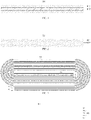
FIG. 5 ) is provided by the inventor, and is formed by winding aflexible battery sheet 100 as illustrated inFIG. 4 . Thewound battery 300 may include thebattery sheet 100 and aseparator 201. Thebattery sheet 100 may include acurrent collector 200, a positiveactive layer 104, and a negativeactive layer 105. Reference of a winding mode of thebattery sheet 100 can be made toFIG. 6 , the positiveactive layer 104 is in an inner circle layer, and the negativeactive layer 105 is in an outer circle layer. - The
current collector 200 may be integrated (an integrated structure) and flexible. The integrated structure of thecurrent collector 200 is realized by, for example, taking an insulatinglayer 101 as a substrate and respectively forming apositive metal layer 102 and anegative metal layer 103 on two opposite surfaces of the insulatinglayer 101. In some implementations, conductive metal layers may be formed on two surfaces (such as an upper surface and a lower surface in the figure) in the thickness direction of a film-like insulatinglayer 101 by selecting a thin film material made of plastic, resin, rubber, etc., and by evaporation deposition, etc. In such a structure, the insulatinglayer 101 can have ideal flexibility by selection of material, and deposited metal layers have small and uniform thicknesses. Therefore, a flexible characteristic of thecurrent collector 200 is ensured, while the existing positive current collector and the existing negative current collector are also integrated together in a mode of electrical insulation/electrical isolation, and a subsequent tedious operation of aligning the positive electrode and the negative electrode is avoided. - Different from the related art in which each layer is arranged by simple lamination, since the battery sheet with the integrated structure is adopted in the present disclosure, the battery sheet can be fabricated to have a relatively thin thickness and a specification can be more easily determined, thereby reducing the thickness and facilitating an alignment operation during winding.
- Exemplarily, in a flexible
current collector 200 with an integrated structure, the insulatinglayer 101 located in the middle (between thepositive metal layer 102 and the negative metal layer 103), for example, may be made of biaxially oriented polypropylene (BOPP) film. Alternatively, the insulatinglayer 101 may be made of a material such as Polyethylene Terephthalate (PET), Polyimide (PI), etc. Thepositive metal layer 102 may be made of aluminum and thenegative metal layer 103 may be made of copper. The insulating layer can be properly selected according to different choices to further reduce the thickness and weight of the wound battery (thinner and lighter), thereby improving the energy density. - The positive
active layer 104 and the negativeactive layer 105 can be correspondingly coated on thepositive metal layer 102 and thenegative metal layer 103 by fabricating corresponding viscous slurries, thereby correspondingly forming theflexible battery sheet 100 with the integrated structure. Exemplarily, the positiveactive layer 104 may be made of LiFeSO4 and the negative active material may be made of graphite. - Therefore, through the above process, the
current collector 200 with the integrated structure formed by the positiveactive layer 104, the negativeactive layer 105, and thecurrent collector 200 can be obtained. - The
separator 201 may be made of, for example, woven film, nonwoven film (nonwoven cloth), microporous film, composite film, separator paper, calendered film, etc. Obviously, if just the abovecurrent collector 200 is wound, the positive electrode will be in direct contact with the negative electrode (substantially the positiveactive layer 104 is in contact with the negative active layer 105). Therefore, theseparator 201 can be used as an insulating material to isolate a positive active material layer from a negative material layer, to avoid a problem of short circuit. - It should be noted that a surface of the positive
active layer 104 in thecurrent collector 200 may be covered by the separator 201 (a first case, as illustrated inFIG. 8 ), or a surface of the negativeactive layer 105 in thecurrent collector 200 may be covered by the separator 201 (a second case, as illustrated inFIG. 7 ), or surfaces of the positiveactive layer 104 and the negativeactive layer 105 each are covered by separators 201 (a third case, as illustrated inFIG. 9 ). - In addition, as an alternative solution, arrangement of the
separator 201 may be further adjusted. Exemplarily, at an outermost circle of thewound battery 300, theseparator 201 extends to the surface of the positiveactive layer 104 or the surface of the negativeactive layer 105. For example, on the flexible battery sheet forming the outermost circle of the wound battery, the separator may be laminated on and cover the surface of the positive active layer or the negative active layer of the outermost circle of flexible battery sheet. - Alternatively, for example, a length of the
separator 201 is controlled, such that in thewound battery 300 formed by winding, theseparator 201 extends to an innermost circle of thewound battery 300 and forms an inner circle section. For example, on the flexible battery sheet forming the innermost circle of the wound battery, the separator may be laminated on and cover the surface of the positive active layer or the negative active layer of the innermost circle of the flexible battery sheet. - The "innermost circle" may be an innermost ring layer among the ring layers formed by winding of the battery sheet, for example, it may be understood as a "first wound circle" which is between an initial wound end of the flexible battery sheet and a second folding portion formed during winding, and a folding portion is a transition section where an extension direction changes. Accordingly, the "outermost circle" may be an outermost ring layer among the ring layers formed by winding of the battery sheet, for example, it may be understood as a "last wound circle" which is between an ending wound end of the flexible battery sheet and a penultimate folding portion formed during winding.
- Alternatively, the inner circle section may be double-layer (a solution illustrated in
FIG. 5 ), or the inner circle section may be single-layer. - In other implementations, the innermost circle of the
wound battery 300 may also not be provided with theseparator 201, which is based on the consideration that the innermost circle layer of thewound battery 300 is only formed by winding an active material layer. The active material layer may be the positive active material layer or the negative active material layer, which is different according to winding modes. The "winding mode" means that the negativeactive layer 105 is placed in the inner layer for winding, or the positiveactive layer 104 is placed in the inner layer for winding. - In addition, corresponding to the above, when the innermost circle of the
wound battery 300 has the inner circle section, theseparator 201 generally has a length identical to or slightly shorter than thecurrent collector 200, for example, half of the length of the innermost circle. When the innermost circle of thewound battery 300 has no inner circle section, theseparator 201 usually has a length shorter than thecurrent collector 200. - On this basis, an
improved wound battery 300 provided by the inventor in the implementations of the present disclosure can be obtained by combining the abovecurrent collector 200 with the integrated structure and theseparator 201 and then winding. In addition, in terms of structure, thewound battery 300 has a two-layer structure (the above first case and the above second case) or a three-layer structure (the above third case). Compared with the aforementioned four-layer structure of thewound battery 900, thewound battery 300 in the implementations of the present disclosure has a more compact structure, and fewer layers laminated by independent structural layers. Therefore, a winding speed is faster, and a winding effect is greater. In addition, the energy density of thewound battery 300 can also be improved, and easy and accurate alignment of the positive electrode and the negative electrode can also be achieved (compared with assembly alignment of an independent positive electrode and an independent negative electrode in the aforementioned wound battery 900). - Alternatively, as an improvement, a protective structure may be introduced on the basis of the
above wound battery 300 to facilitate controlling occurrence of danger in extreme cases. For example, when a battery is severely impacted or squeezed, short circuit may occur inside the battery, and the short circuit will lead to accumulation of heat. When the heat is unable to be effectively and timely dissipated, the heat may be out of control, thereby resulting in fire, explosion, etc. Therefore, in order to overcome or alleviate this problem, thecurrent collector 200 in the implementations of the present disclosure is properly adjusted. For example, active material layers formed on the surfaces of thepositive metal layer 102 and thenegative metal layer 103 of thecurrent collector 200 are controlled to enable a part of thepositive metal layer 102 and a part of thenegative metal layer 103 to be exposed, which is also known as enabling the part of thepositive metal layer 102 and the part of thenegative metal layer 103 to be vacant, that is, no active materials are disposed at such partial regions. - For example, in a region of the innermost circle of the
wound battery 300, no active materials are disposed at both thepositive metal layer 102 and thenegative metal layer 103 corresponding to thepositive metal layer 102. For example, a first exposed arrangement solution: in the region of the innermost circle of thewound battery 300, such as an initial wound section of the battery sheet, also known as a head section (as illustrated inFIG. 10 ), thepositive metal layer 102 has a first positive exposed section located at the region, and thenegative metal layer 103 has a first negative exposed section located at the region and corresponding to the first positive exposed section. Alternatively, a second exposed arrangement solution: in the region of the outermost circle of thewound battery 300, such as an ending wound section of the battery sheet, also known as a terminal section (as illustrated inFIG. 10 ), thepositive metal layer 102 has a second negative exposed section located at the region and corresponding to the second positive exposed section. - Alternatively, in the structure of the
wound battery 300, the above first exposed arrangement solution and the above second exposed arrangement solution are implemented simultaneously, as illustrated inFIG. 10 . - Due to the above exposed solution of the
current collector 200, thepositive metal layer 102 and thenegative metal layer 103 have sections at which no corresponding active materials are disposed, and both positions are corresponding to each other and isolated by the insulatinglayer 101, thereby forming a laminated structure of exposed aluminum-insulating layer-exposed copper. In this structure, when the wound battery is excessively stimulated by the outside (enough to cause short circuit), compared with sections at which the active materials are disposed, sections at which no active materials are disposed will be short-circuited first and can shunt short-circuit current, such that this part can disperse a thermal effect of short circuit and avoid excessive "accumulation" of heat, thereby solving a problem of ignition and explosion caused by excessive heating. - In order to make the objects, technical solutions and advantages of the implementations of the present disclosure clearer, the technical solutions of the implementations of the present disclosure will be described below clearly and completely with reference to the accompanying drawings in the implementations of the present disclosure. Obviously, the implementations to be described are some, but not all of the implementations of the present disclosure. Generally, the components of the implementations of the present disclosure, as described and illustrated in the accompanying drawings herein, may be arranged and designed in a wide variety of different configurations. Therefore, the following detailed description of the implementations of the present disclosure, as provided in the accompanying drawings, is not intended to limit the protection scope of the present disclosure as claimed, but is merely representative of selected implementations of the present disclosure. Based on the implementations of the present disclosure, all the other implementations obtained by those of ordinary skill in the art without inventive efforts would fall within the protection scope of the present disclosure.
- It should be noted that similar signs and letters indicate similar items in the following accompanying drawings, and therefore, once an item is defined in an accompanying drawing, it is not necessary to further define or explain it in the subsequent accompanying drawings.
- In the description of the implementations of the present disclosure, it should be noted that orientation or positional relations indicated by terms such as "inside", "outside", etc., are orientation or positional relations based on the accompanying drawings, or orientation or positional relations in which the application product is placed conventionally in use, or only for facilitating description of the present disclosure and simplifying the description, rather than indicating or implying that the referred devices or elements must be in a particular orientation, and be constructed and operated in the particular orientation, and therefore they should not be construed as position limiting the present disclosure. In addition, terms such as "first", "second", and "third" are used only for distinguishing the description, and should not be construed as indicating or implying relativity importance.
- In the description of the present disclosure, it should be further noted that unless otherwise expressly specified or defined, terms such as "provide", "mount", "couple", and "connect" should be understood broadly, and for example, a fixed connection, or a detachable connection, or an integrated connection; may be a mechanical connection or an electric connection; and may be a direct connection, or an indirect connection via an intermediate medium, or may be an internal communication between two elements. The specific meanings of the above terms in the present disclosure could be understood by those of ordinary skill in the art according to specific situations.
- The foregoing is only a preferred implementation of the present disclosure and is not intended to limit the disclosure which may be subject to various modifications and variations to those skilled in the art. Any modifications, equivalents, modifications, etc. made within the spirit and principles of this disclosure shall be within the scope of protection of this disclosure.
- To sum up, the wound battery is provided in the present disclosure, the thickness of which can be effectively reduced, and high requirements for alignment accuracy are reduced, such that the wound battery can be fabricated with the higher winding density to obtain the higher energy density, thereby improving or even solving problems of a large wound battery thickness and limited increase in energy density.
Claims (18)
- A wound battery mainly formed by winding a battery sheet, comprising:a flexible battery sheet with an integrated structure, wherein the battery sheet comprises a current collector, a positive active layer, and a negative active layer, the current collector has an insulating layer as a substrate, and a positive metal layer and a negative metal layer which are formed on surfaces of two sides of the insulating layer, the positive active layer is formed on a surface of the positive metal layer, and the negative active layer is formed on a surface of the negative metal layer; andan insulating separator laminated on and covering a surface of the positive active layer and/or a surface of the negative active layer, and configured to prevent the positive active layer from directly contacting the negative active layer.
- The wound battery of claim 1, wherein the separator extends to an innermost circle of the wound battery and forms an inner circle section.
- The wound battery of claim 2, wherein the inner circle section is double-layer.
- The wound battery of claim 2, wherein the inner circle section is single-layer.
- The wound battery of claim 1, wherein an innermost circle of the wound battery is not provided with the separator.
- The wound battery of any of claims 1 to 4, wherein the separator has a length identical to or slightly shorter than the current collector.
- The wound battery of any of claims 1 to 6, wherein active material layers formed on surfaces of the positive metal layer and the negative metal layer of the current collector are adjusted to enable a part of the positive metal layer and a part of the negative metal layer to be exposed, that is, no active material layer is disposed.
- The wound battery of claim 7, wherein in an innermost circle of the wound battery, the positive metal layer has a first positive exposed section located in a region of the innermost circle and the negative metal layer has a first negative exposed section located in the region of the innermost circle and corresponding to the first positive exposed section.
- The wound battery of claim 8, wherein the region of the innermost circle comprises an initial wound section of the flexible battery sheet.
- The wound battery of claims 7, 8, or 9, wherein in an outermost circle of the wound battery, the positive metal layer has a second positive exposed section located in a region of the outermost circle and the negative metal layer has a second negative exposed section located in the region of the outermost circle and corresponding to the second positive exposed section.
- The wound battery of claim 10, wherein the region of the outermost circle comprises an ending wound section of the flexible battery sheet.
- The wound battery of any of claims 1 to 11, wherein the separator extends to the surface of the positive active layer and the surface of the negative active layer in an outermost circle of the wound battery.
- The wound battery of any of claims 1 to 12, wherein the positive active layer is made of LiFeSO4.
- The wound battery of any of claims 1 to 13, wherein the negative active layer is made of graphite.
- The wound battery of any of claims 1 to 14, wherein the positive metal layer is made of aluminum.
- The wound battery of any of claims 1 to 15, wherein the negative metal layer is made of copper.
- The wound battery of any of claims 1 to 16, wherein the insulating layer is made of a material selected from a group comprising: plastic, which preferably is biaxially oriented polypropylene (BOPP) film, polyethylene terephthalate (PET), and polyimide (PI); resin; and/or rubber.
- The wound battery of any of claims 1 to 17, wherein the positive metal layer and the negative metal layer which have relatively small and uniform thicknesses are formed on two surfaces of the insulating layer in a thickness direction of the insulating layer by evaporation deposition respectively.
Applications Claiming Priority (2)
| Application Number | Priority Date | Filing Date | Title |
|---|---|---|---|
| CN202021527556.3U CN212659582U (en) | 2020-07-28 | 2020-07-28 | Winding battery |
| PCT/CN2021/108725 WO2022022527A1 (en) | 2020-07-28 | 2021-07-27 | Wound battery |
Publications (2)
| Publication Number | Publication Date |
|---|---|
| EP4109622A1 true EP4109622A1 (en) | 2022-12-28 |
| EP4109622A4 EP4109622A4 (en) | 2024-05-15 |
Family
ID=74770448
Family Applications (1)
| Application Number | Title | Priority Date | Filing Date |
|---|---|---|---|
| EP21850342.3A Pending EP4109622A4 (en) | 2020-07-28 | 2021-07-27 | Wound battery |
Country Status (4)
| Country | Link |
|---|---|
| US (1) | US12482865B2 (en) |
| EP (1) | EP4109622A4 (en) |
| CN (1) | CN212659582U (en) |
| WO (1) | WO2022022527A1 (en) |
Families Citing this family (1)
| Publication number | Priority date | Publication date | Assignee | Title |
|---|---|---|---|---|
| CN212659582U (en) * | 2020-07-28 | 2021-03-05 | 深圳市海鸿新能源技术有限公司 | Winding battery |
Family Cites Families (7)
| Publication number | Priority date | Publication date | Assignee | Title |
|---|---|---|---|---|
| CN100527492C (en) * | 2005-12-30 | 2009-08-12 | 比亚迪股份有限公司 | Collector, lithium secondary battery comprising the collector and method for preparation the same |
| CN103003992B (en) * | 2010-03-11 | 2015-05-20 | 丰田自动车株式会社 | Current collector and manufacturing method thereof, battery and manufacturing method thereof |
| CN106898825B (en) * | 2017-05-03 | 2019-02-05 | 江苏强劲新能源科技有限公司 | A kind of preparation method of bipolarity Zinc ion battery |
| CN107240721B (en) * | 2017-05-27 | 2020-01-31 | 深圳市雄韬电源科技股份有限公司 | Bipolar electrode, lithium ion battery and manufacturing method of lithium ion battery |
| CN111740066B (en) * | 2019-03-25 | 2023-05-12 | 宁德新能源科技有限公司 | Pole piece and electrode assembly with same |
| CN111180737B (en) * | 2019-05-31 | 2021-08-03 | 宁德时代新能源科技股份有限公司 | Lithium-ion secondary battery, cell and negative electrode |
| CN212659582U (en) * | 2020-07-28 | 2021-03-05 | 深圳市海鸿新能源技术有限公司 | Winding battery |
-
2020
- 2020-07-28 CN CN202021527556.3U patent/CN212659582U/en active Active
-
2021
- 2021-07-27 WO PCT/CN2021/108725 patent/WO2022022527A1/en not_active Ceased
- 2021-07-27 EP EP21850342.3A patent/EP4109622A4/en active Pending
-
2022
- 2022-09-22 US US17/950,482 patent/US12482865B2/en active Active
Also Published As
| Publication number | Publication date |
|---|---|
| US12482865B2 (en) | 2025-11-25 |
| WO2022022527A1 (en) | 2022-02-03 |
| CN212659582U (en) | 2021-03-05 |
| US20230013882A1 (en) | 2023-01-19 |
| EP4109622A4 (en) | 2024-05-15 |
Similar Documents
| Publication | Publication Date | Title |
|---|---|---|
| CN113330631B (en) | Electrode assembly, electrochemical device and electronic device | |
| EP3048656B1 (en) | Rechargeable battery | |
| EP0851523A1 (en) | Lithium ion battery | |
| US8021781B2 (en) | Jelly-roll type electrode assembly and secondary battery employing the same | |
| CN114902462B (en) | Secondary battery | |
| WO2021131879A1 (en) | Secondary battery | |
| US20060068275A1 (en) | Pouch-type lithium secondary battery and fabrication method thereof | |
| JP2005222884A (en) | Electrode laminated battery | |
| US20230246308A1 (en) | Electrochemical apparatus and electronic device | |
| US12482865B2 (en) | Wound battery and energy storage device | |
| CN107210453A (en) | The design of solid state battery | |
| KR20210150924A (en) | High-energy density Pouch type secondary batter and manufacturing method of the same | |
| EP4550494A1 (en) | Electrode assembly and rechargeable battery with the same | |
| KR102837703B1 (en) | Elctrode assembly and electrochemical device comprising the same | |
| JP2019106388A (en) | Power storage element, and manufacturing method of power storage element | |
| KR20240056394A (en) | Elctrode assembly and electrochemical device comprising the same | |
| WO2017208509A1 (en) | Power storage device and method for producing same | |
| US20250372728A1 (en) | Electrode assembly and method for manufacturing same | |
| CN121306939B (en) | Battery cell, energy storage device and electric equipment | |
| KR102837704B1 (en) | Elctrode assembly and electrochemical device comprising the same | |
| JP7726826B2 (en) | Battery Module | |
| JP7813633B2 (en) | Cylindrical Cells and Battery Modules | |
| CN114188501B (en) | Electrochemical devices and electronic devices | |
| US20260128350A1 (en) | Electrode assembly and secondary battery including the same | |
| US20240162525A1 (en) | Electrode assembly, secondary battery, battery pack, and electrical apparatus |
Legal Events
| Date | Code | Title | Description |
|---|---|---|---|
| STAA | Information on the status of an ep patent application or granted ep patent |
Free format text: STATUS: THE INTERNATIONAL PUBLICATION HAS BEEN MADE |
|
| PUAI | Public reference made under article 153(3) epc to a published international application that has entered the european phase |
Free format text: ORIGINAL CODE: 0009012 |
|
| STAA | Information on the status of an ep patent application or granted ep patent |
Free format text: STATUS: REQUEST FOR EXAMINATION WAS MADE |
|
| 17P | Request for examination filed |
Effective date: 20220920 |
|
| AK | Designated contracting states |
Kind code of ref document: A1 Designated state(s): AL AT BE BG CH CY CZ DE DK EE ES FI FR GB GR HR HU IE IS IT LI LT LU LV MC MK MT NL NO PL PT RO RS SE SI SK SM TR |
|
| DAV | Request for validation of the european patent (deleted) | ||
| DAX | Request for extension of the european patent (deleted) | ||
| A4 | Supplementary search report drawn up and despatched |
Effective date: 20240416 |
|
| RIC1 | Information provided on ipc code assigned before grant |
Ipc: H01M 10/0587 20100101ALI20240410BHEP Ipc: H01M 4/587 20100101ALI20240410BHEP Ipc: H01M 4/58 20100101ALI20240410BHEP Ipc: H01M 10/04 20060101ALI20240410BHEP Ipc: H01M 4/66 20060101ALI20240410BHEP Ipc: H01M 10/0525 20100101ALI20240410BHEP Ipc: H01M 10/0583 20100101AFI20240410BHEP |