EP4109425A1 - Paper-sheet handling device - Google Patents
Paper-sheet handling device Download PDFInfo
- Publication number
- EP4109425A1 EP4109425A1 EP20919509.8A EP20919509A EP4109425A1 EP 4109425 A1 EP4109425 A1 EP 4109425A1 EP 20919509 A EP20919509 A EP 20919509A EP 4109425 A1 EP4109425 A1 EP 4109425A1
- Authority
- EP
- European Patent Office
- Prior art keywords
- take
- section
- banknote
- facing
- space
- Prior art date
- Legal status (The legal status is an assumption and is not a legal conclusion. Google has not performed a legal analysis and makes no representation as to the accuracy of the status listed.)
- Granted
Links
Images




Classifications
-
- G—PHYSICS
- G07—CHECKING-DEVICES
- G07D—HANDLING OF COINS OR VALUABLE PAPERS, e.g. TESTING, SORTING BY DENOMINATIONS, COUNTING, DISPENSING, CHANGING OR DEPOSITING
- G07D11/00—Devices accepting coins; Devices accepting, dispensing, sorting or counting valuable papers
- G07D11/10—Mechanical details
- G07D11/14—Inlet or outlet ports
-
- G—PHYSICS
- G07—CHECKING-DEVICES
- G07D—HANDLING OF COINS OR VALUABLE PAPERS, e.g. TESTING, SORTING BY DENOMINATIONS, COUNTING, DISPENSING, CHANGING OR DEPOSITING
- G07D11/00—Devices accepting coins; Devices accepting, dispensing, sorting or counting valuable papers
- G07D11/10—Mechanical details
- G07D11/12—Containers for valuable papers
- G07D11/13—Containers for valuable papers with internal means for handling valuable papers
-
- G—PHYSICS
- G07—CHECKING-DEVICES
- G07D—HANDLING OF COINS OR VALUABLE PAPERS, e.g. TESTING, SORTING BY DENOMINATIONS, COUNTING, DISPENSING, CHANGING OR DEPOSITING
- G07D2211/00—Paper-money handling devices
Definitions
- the present invention relates to a paper sheet handling apparatus.
- a banknote insertion/withdrawal apparatus has also been proposed that is provided with a banknote press for pressing banknotes to be withdrawn that have been stored in a storage unit, and a pushing member for pushing lower portions of the banknotes to be withdrawn when the banknote press is separated from the banknotes to be withdrawn (see, for example, patent document 2).
- an automatic transaction apparatus such as an automated teller machine (ATM) includes a banknote insertion/withdrawal unit for inserting a banknote to be deposited and taking out a banknote to be withdrawn.
- ATM automated teller machine
- Such a banknote insertion/withdrawal unit may include a pusher that is movably disposed between a stage and a roof, forms an insertion space between the pusher and the stage, and forms a take-out space between the pusher and the roof.
- the pusher desirably assumes a tapered shape that becomes thinner toward an insertion/take-out port such that the insertion space and the take-out space become wider toward the insertion/take-out port so as to prevent the inserting of a hand from being interfered with when a banknote is inserted into the insertion space or when a banknote is taken out from the take-out space.
- the pusher assuming the tapered shape within the insertion/take-out space causes the pusher to have an increased thickness on the inner side of the banknote insertion/withdrawal unit because the pusher assumes the tapered shape.
- the insertion amount and the take-out amount of banknotes may decrease, or the insertion/take-out space may be large-sized.
- An object of the present invention is to provide a paper sheet handling apparatus that can allow a paper sheet to be easily inserted or taken out, and increase the insertion amount and the take-out amount of paper sheets with a simple configuration.
- a disclosed paper sheet handling apparatus includes: first and second facing sections that are disposed to face each other across an insertion/take-out space into which a paper sheet is inserted through an insertion/take-out port and from which a paper sheet is taken out through the insertion/take-out port; and a partition section that is disposed between the first and second facing sections so as to be capable of moving in a facing direction in which the first and second facing sections face each other, forms, within the insertion/take-out space, an insertion space between the partition section and the first facing section into which a paper sheet is inserted through the insertion/take-out port, and forms, within the insertion/take-out space, a take-out space between the partition section and the second facing section from which a paper sheet is taken out through the insertion/take-out port, wherein the partition section includes a movable member provided at a leading end portion of the partition section on an insertion/take-out port side and capable of moving toward each of the first facing section and the second facing section.
- a disclosed paper sheet handling apparatus can allow a paper sheet to be easily inserted or taken out, and increase the insertion amount and the take-out amount of paper sheets with a simple configuration.
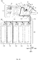
- FIG. 1 is a left side view illustrating the internal configuration of the automatic transaction apparatus 100.
- the up-down direction, the front-rear direction, and the left-right direction indicated in FIG. 1 and FIGS. 2A-4B are merely examples, with the customer side of the automatic transaction apparatus 100 as the front direction.
- the up-down direction may be a vertical direction
- the front-rear direction and the left-right direction may be horizontal directions.
- the automatic transaction apparatus 100 depicted in FIG. 1 is, for example, an ATM, a bill recycle unit (BRU), a cash dispenser (CD), or a teller cash recycler (TCR) and includes a body unit 110, an intermediate conveyance section 120, and a storage unit 130.
- the body unit 110 and the storage unit 130 may be disposed within different spaces with a partition (not illustrated) therebetween, and the intermediate conveyance section 120 may convey a banknote B (see FIG. 2A ) through the partition.
- the banknote B is an example of a paper sheet.
- the body unit 110 includes a banknote insertion/withdrawal unit 1, conveyance sections 111 and 113, a validation unit 112, a temporary retention section 114, and a reject unit 115.
- the banknote insertion/withdrawal unit 1 includes a stage 10, a roof 20, a pusher 30, a take-in conveyance section 40, a discharge conveyance section 50, a front face panel 60, a shutter 70, and a first contact section 80 (see FIG. 3B ). Note that the banknote insertion/withdrawal unit 1 alone can also be considered to be an example of a paper sheet handling apparatus.
- the stage 10, the roof 20, the pusher 30, and the first contact section 80 will be described hereinafter by referring to FIGS. 3A-3C , 4A , and 4B .
- the take-in conveyance section 40 conveys a banknote B inserted between the stage 10 and the pusher 30 so as to take the same into the automatic transaction apparatus 100.
- the discharge conveyance section 50 discharges a banknote B to the space between the roof 20 and the pusher 30.
- the front face panel 60 is disposed on an upper front face of the automatic transaction apparatus 100 so as to be inclined in the vertical direction and the horizontal direction, such that portions of the front face panel 60 at a higher position are located at a more rearward position.
- the front face panel 60 is provided with an insertion/take-out port 61.
- FIG. 1 depicts, by using a solid line, the shutter 70 with an open state attained, and depicts, by using a dotted line, the shutter 70 with a closed state attained.
- the conveyance section 111 transports a banknote B from the banknote insertion/withdrawal unit 1 to the validation unit 112, and transports a banknote B from the validation unit 112 to the intermediate conveyance section 120, or vice versa.
- the validation unit 112 determines a banknote B for, for example, authenticity, dirt, and/or corner folding.
- the conveyance section 113 transports a banknote B from the validation unit 112 to the temporary retention section 114, or vice versa, and transports a banknote B from the validation unit 112 to the banknote insertion/withdrawal unit 1.
- the temporary retention section 114 temporarily stores a banknote B inserted into the banknote insertion/withdrawal unit 1 and determined as being normal by the validation unit 112.
- the reject unit 115 stores banknotes B not to be returned, among banknotes B determined as being abnormal by the validation unit 112.
- the intermediate conveyance section 120 transports a banknote B from the body unit 110 to the storage unit 130, or vice versa.
- the storage unit 130 is disposed below the body unit 110 and includes a plurality of banknote storage cassettes 131, 132, 133, 134, and 135 and a storage conveyance section 136.
- the plurality of banknote storage cassettes 131-135 may each store banknotes B of a different denomination.
- the banknote storage cassettes 131-135 can send out stored banknotes B.
- banknotes B stored in the banknote storage cassettes 131-135 are used for withdrawal.
- the storage conveyance section 136 conveys a banknote B from the intermediate conveyance section 120 to each of the banknote storage cassettes 131-135, or vice versa.
- FIGS. 2A-2C are explanatory diagrams for illustrating transporting routes R1-R4 for banknotes B within the automatic transaction apparatus 100.
- a banknote B inserted into the banknote insertion/withdrawal unit 1 is transported to the validation unit 112 by the take-in conveyance section 40 and the conveyance section 111.
- a banknote B determined as being normal by the validation unit 112 is conveyed to the temporary retention section 114 by the conveyance section 113.
- a banknote B determined as being abnormal by the validation unit 112 (e.g., false banknote) is returned to the banknote insertion/withdrawal unit 1 by the conveyance section 113 and the discharge conveyance section 50.
- banknotes B temporarily stored in the temporary retention section 114 are conveyed to the banknote storage cassettes 131-135 by the conveyance section 113, the validation unit 112, the conveyance section 111, the intermediate conveyance section 120, and the storage conveyance section 136.
- banknotes B stored in the banknote storage cassettes 131-135 are sent out, at the time of withdrawal, to the banknote insertion/withdrawal unit 1 by the storage conveyance section 136, the intermediate conveyance section 120, the conveyance section 111, the validation unit 112, the conveyance section 113, and the discharge conveyance section 50.
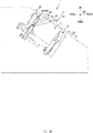
- FIGS. 3A-3C are explanatory diagrams for illustrating the money inserting operation performed by the banknote insertion/withdrawal unit 1.
- FIGS. 4A and 4B are explanatory diagrams for illustrating the banknote withdrawing operation performed by the banknote insertion/withdrawal unit 1.
- the stage 10 and the roof 20 are disposed to face each other across an insertion/take-out space S.
- a banknote B is inserted through the insertion/take-out port 61 of the front face panel 60, which is indicated by a two-dot dash line in FIGS. 3A-4B , into the insertion/take-out space S.
- a banknote B is also taken out from the insertion/take-out space S through the insertion/take-out port 61.
- the stage 10 and the roof 20 are disposed to be inclined in the vertical direction and the horizontal direction so as to be parallel to an insertion/take-out direction D2 in which a banknote B is inserted or taken out, such that portions of the stage 10 and the roof 20 at a more frontward position are located at a higher position.
- a facing direction D1 in which the stage 10 and the roof 20 face each other is orthogonal to the insertion/take-out direction D2, and inclined in the vertical direction and the horizontal direction such that portions at a more rearward position are located at a higher position.
- the stage 10 and the roof 20 can move in the facing direction D1.
- the stage 10 is an example of the first facing section
- the roof 20 is an example of the second facing section.
- the pusher 30 is an example of the partition section disposed between the stage 10 and the roof 20 so as to be capable of moving in the facing direction D1 in which the stage 10 and the roof 20 face each other.
- the pusher 30 forms, within the insertion/take-out space S, an insertion space S1 between the pusher 30 and the stage 10 into which a banknote B is inserted through the insertion/take-out port 61.
- the pusher 30 forms a take-out space S2 between the pusher 30 and the roof 20 from which a banknote B is taken out through the insertion/take-out port 61.
- the pusher 30 includes a movable member 31 provided at a leading end portion of the pusher 30 on the insertion/take-out port 61 side and capable of moving toward each of the stage 10 (see FIG. 4B ) and the roof 20 (see FIG. 3B ).
- the movable member 31 may be provided only at a portion of the pusher 30 in the vicinity of the center in a left-right direction intersecting the facing direction D1 and the insertion/take-out direction D2.
- the movable member 31 is supported to be capable of turning about a turn shaft 32.
- the movable member 31 may be biased by an elastic body such as a torsion spring so as to be kept positioned parallel to the stage 10 and the roof 20.
- a press-reception projection 31a protruding downward (toward the stage 10) is provided on a portion of the movable member 31 on the opposite side of the turn shaft 32 from the insertion/take-out port 61.
- the first contact section 80 is a projection provided rearward of the insertion/take-out port 61 and protruding downward from the back side of the front face panel 60.
- the pusher 30 is located at an initial position P0 and stays close to the roof 20.
- the pusher 30 is located at an insertion position P1 and forms the insertion space S1 between the pusher 30 and the stage 10.
- the movable member 31 contacts the first contact section 80 and is pressed against the elastic force of the above-described elastic body, thereby moving to tilt toward the roof 20.
- the insertion space S1 (the space between the pusher 30 and the stage 10) becomes wider toward the insertion/take-out port 61, so that a customer can easily insert a banknote B.
- the movable member 31 may move to tilt toward the roof 20 by means of, for example, a driving force of a driving means (not illustrated).
- the pusher 30 moves toward the stage 10 and reaches a take-in position P2 at which the pusher 30 and the stage 10 sandwich the banknote B.
- the stage 10 and the pusher 30 may move forward and thus move obliquely downward, i.e., move toward the take-in conveyance section 40 depicted in FIG. 1 , and the banknote B may be transported toward the conveyance section 111 by the take-in conveyance section 40, with, for example, a pick roller of the take-in conveyance section 40 protruding through an opening (not illustrated) provided in the stage 10.
- banknotes B At the time of withdrawal of banknotes B, as indicated in FIG. 4A , as many banknotes B as are scheduled to be sent out are transported to the space between the roof 20 and the pusher 30, which is located at a send-out position P3, by the discharge conveyance section 50 depicted in FIG. 1 .
- the pusher 30 moves toward the stage 10 together with the roof 20.
- the pusher 30 is located at a take-out position P4 and forms the take-out space S2 between the pusher 30 and the roof 20.
- the press-reception projection 31a contacts the stage 10 and is pressed against the elastic force of the above-described elastic body, thereby causing the movable member 31 to move to tilt toward the stage 10.
- the take-out space S2 (the space between the pusher 30 and the roof 20) becomes wider toward the insertion/take-out port 61, so that a customer can easily take out the banknote B.
- the stage 10 functions as an example of a second contact section that contacts the movable member 31 so as to move the movable member 31 toward the stage 10.
- the movable member 31 may move to tilt toward the stage 10 by means of, for example, a driving force of the driving means (not illustrated).
- the movable member 31 may also contact a second contact section other than the stage 10, so as to move to tilt toward the stage 10.
- a portion of the movable member 31 other than the press-reception projection 31a may contact the stage 10 (second contact section).
- a supporting section 90 that is disposed to face the insertion/take-out port 61 and supports the banknote B moves toward the insertion/take-out port 61. Then, the customer takes out the banknote B.
- the automatic transaction apparatus 100 i.e., an example of the paper sheet handling apparatus, includes: the stage 10, i.e., an example of the first facing section; the roof 20, i.e., an example of the second facing section; and the pusher 30, i.e., an example of the partition section.
- the stage 10 and the roof 20 are disposed to face each other across the insertion/take-out space S into which a banknote B, i.e., an example of a paper sheet, is inserted through the insertion/take-out port 61 and from which a banknote B is taken out through the insertion/take-out port 61.
- the pusher 30 is disposed between the stage 10 and the roof 20 so as to be capable of moving in the facing direction D1 in which the stage 10 and the roof 20 face each other.
- the pusher 30 forms, within the insertion/take-out space S, the insertion space S1 between the pusher 30 and the stage 10 into which a banknote B is inserted through the insertion/take-out port 61, and forms, within the insertion/take-out space S, the take-out space S2 between the pusher 30 and the roof 20 from which a banknote B is taken out through the insertion/take-out port 61.
- the pusher 30 includes the movable member 31 provided at a leading end portion of the pusher 30 on the insertion/take-out port 61 side and capable of moving toward each of the stage 10 and the roof 20.
- the movable member 31 can move toward the roof 20 so as to make the insertion space S1 between the stage 10 and the pusher 30 wider toward the insertion/take-out port 61, so that a customer can easily insert a banknote B.
- the movable member 31 can also move toward the stage 10 so as to make the take-out space S2 between the roof 20 and the pusher 30 wider toward the insertion/take-out port 61, so that a customer can easily take out a banknote B.
- the pusher 30 may have a tapered shape such that the thickness thereof in the facing direction D1 decreases toward the insertion/take-out port 61 (comparative example).
- the insertion amount and the take-out amount of banknotes B decrease, or the insertion/take-out space S is large-sized.
- the insertion space S1 and the take-out space S2 can be made wider toward the insertion/take-out port 61 without the pusher 30 having a tapered shape.
- the present embodiment can allow a banknote B (paper sheet) to be easily inserted or taken out, and increase the insertion amount and the take-out amount of banknotes B with the simple configuration.
- the movable member 31 moves toward the roof 20, with the pusher 30 being located at the insertion position P1 at which the pusher 30 forms the insertion space S1 between the pusher 30 and the stage 10; and, at the time of taking out a banknote B, the movable member 31 moves toward the stage 10, with the pusher 30 being located at the take-out position P4 at which the pusher 30 forms the take-out space S2 between the pusher 30 and the roof 20.
- the movable member 31 can make the insertion space S1 wider toward the insertion/take-out port 61 by moving toward the roof 20.
- the movable member 31 can make the take-out space S2 wider toward the insertion/take-out port 61 by moving toward the stage 10.
- a banknote B can be easily inserted or taken out.
- the automatic transaction apparatus 100 includes: the first contact section 80 that contacts the movable member 31 so as to move the movable member 31 toward the roof 20 when the pusher 30 is located at the insertion position P1; and the stage 10, i.e., an example of the second contact section, that contacts the movable member 31 so as to move the movable member 31 toward the stage 10 when the pusher 30 is located at the take-out position P4.
- the disposing of the driving means for moving the movable member 31 can be omitted.
- the configuration of the banknote insertion/withdrawal unit 1 can be made simpler.
Landscapes
- Physics & Mathematics (AREA)
- General Physics & Mathematics (AREA)
- Pile Receivers (AREA)
- Sheets, Magazines, And Separation Thereof (AREA)
Abstract
Description
- The present invention relates to a paper sheet handling apparatus.
- An automatic transaction apparatus provided with a banknote press for pressing an upper portion of a banknote inserted through a banknote insertion port has been proposed (see, for example, patent document 1).
- A banknote insertion/withdrawal apparatus has also been proposed that is provided with a banknote press for pressing banknotes to be withdrawn that have been stored in a storage unit, and a pushing member for pushing lower portions of the banknotes to be withdrawn when the banknote press is separated from the banknotes to be withdrawn (see, for example, patent document 2).
-
- Patent Document 1:
Japanese Laid-open Patent Publication No. 2009-181372 - Patent Document 2:
Japanese Laid-open Patent Publication No. 2006-53811 - In the meantime, an automatic transaction apparatus such as an automated teller machine (ATM) includes a banknote insertion/withdrawal unit for inserting a banknote to be deposited and taking out a banknote to be withdrawn. Such a banknote insertion/withdrawal unit may include a pusher that is movably disposed between a stage and a roof, forms an insertion space between the pusher and the stage, and forms a take-out space between the pusher and the roof.
- In the banknote insertion/withdrawal unit, the pusher desirably assumes a tapered shape that becomes thinner toward an insertion/take-out port such that the insertion space and the take-out space become wider toward the insertion/take-out port so as to prevent the inserting of a hand from being interfered with when a banknote is inserted into the insertion space or when a banknote is taken out from the take-out space.
- However, disposing the pusher assuming the tapered shape within the insertion/take-out space causes the pusher to have an increased thickness on the inner side of the banknote insertion/withdrawal unit because the pusher assumes the tapered shape. Thus, the insertion amount and the take-out amount of banknotes may decrease, or the insertion/take-out space may be large-sized.
- An object of the present invention is to provide a paper sheet handling apparatus that can allow a paper sheet to be easily inserted or taken out, and increase the insertion amount and the take-out amount of paper sheets with a simple configuration.
- A disclosed paper sheet handling apparatus includes: first and second facing sections that are disposed to face each other across an insertion/take-out space into which a paper sheet is inserted through an insertion/take-out port and from which a paper sheet is taken out through the insertion/take-out port; and a partition section that is disposed between the first and second facing sections so as to be capable of moving in a facing direction in which the first and second facing sections face each other, forms, within the insertion/take-out space, an insertion space between the partition section and the first facing section into which a paper sheet is inserted through the insertion/take-out port, and forms, within the insertion/take-out space, a take-out space between the partition section and the second facing section from which a paper sheet is taken out through the insertion/take-out port, wherein the partition section includes a movable member provided at a leading end portion of the partition section on an insertion/take-out port side and capable of moving toward each of the first facing section and the second facing section.
- A disclosed paper sheet handling apparatus can allow a paper sheet to be easily inserted or taken out, and increase the insertion amount and the take-out amount of paper sheets with a simple configuration.
-
-
FIG. 1 is a left side view illustrating the internal configuration of an automatic transaction apparatus in an embodiment; -
FIG. 2A is an explanatory diagram for illustrating transporting routes for banknotes within an automatic transaction apparatus in an embodiment (example 1); -
FIG. 2B is an explanatory diagram for illustrating a transporting route for banknotes within an automatic transaction apparatus in an embodiment (example 2); -
FIG. 2C is an explanatory diagram for illustrating a transporting route for banknotes within an automatic transaction apparatus in an embodiment (example 3); -
FIG. 3A is an explanatory diagram for illustrating a money inserting operation performed by a banknote insertion/withdrawal unit in an embodiment (example 1); -
FIG. 3B is an explanatory diagram for illustrating a money inserting operation performed by a banknote insertion/withdrawal unit in an embodiment (example 2); -
FIG. 3C is an explanatory diagram for illustrating a money inserting operation performed by a banknote insertion/withdrawal unit in an embodiment (example 3); -
FIG. 4A is an explanatory diagram for illustrating a money withdrawing operation performed by a banknote insertion/withdrawal unit in an embodiment (example 1); and -
FIG. 4B is an explanatory diagram for illustrating a money withdrawing operation performed by a banknote insertion/withdrawal unit in an embodiment (example 2). - With reference to the drawings, the following describes a paper sheet handling apparatus in accordance with an embodiment of the present invention by taking an
automatic transaction apparatus 100 as an example. -
FIG. 1 is a left side view illustrating the internal configuration of theautomatic transaction apparatus 100. - The up-down direction, the front-rear direction, and the left-right direction indicated in
FIG. 1 andFIGS. 2A-4B (described hereinafter) are merely examples, with the customer side of theautomatic transaction apparatus 100 as the front direction. For example, the up-down direction may be a vertical direction, and the front-rear direction and the left-right direction may be horizontal directions. - The
automatic transaction apparatus 100 depicted inFIG. 1 is, for example, an ATM, a bill recycle unit (BRU), a cash dispenser (CD), or a teller cash recycler (TCR) and includes abody unit 110, anintermediate conveyance section 120, and astorage unit 130. As an example, thebody unit 110 and thestorage unit 130 may be disposed within different spaces with a partition (not illustrated) therebetween, and theintermediate conveyance section 120 may convey a banknote B (seeFIG. 2A ) through the partition. Note that the banknote B is an example of a paper sheet. - The
body unit 110 includes a banknote insertion/withdrawal unit 1,conveyance sections validation unit 112, atemporary retention section 114, and areject unit 115. - The banknote insertion/
withdrawal unit 1 includes astage 10, aroof 20, apusher 30, a take-inconveyance section 40, adischarge conveyance section 50, afront face panel 60, ashutter 70, and a first contact section 80 (seeFIG. 3B ). Note that the banknote insertion/withdrawal unit 1 alone can also be considered to be an example of a paper sheet handling apparatus. - The
stage 10, theroof 20, thepusher 30, and thefirst contact section 80 will be described hereinafter by referring toFIGS. 3A-3C ,4A , and4B . - The take-in
conveyance section 40 conveys a banknote B inserted between thestage 10 and thepusher 30 so as to take the same into theautomatic transaction apparatus 100. - The
discharge conveyance section 50 discharges a banknote B to the space between theroof 20 and thepusher 30. - The
front face panel 60 is disposed on an upper front face of theautomatic transaction apparatus 100 so as to be inclined in the vertical direction and the horizontal direction, such that portions of thefront face panel 60 at a higher position are located at a more rearward position. Thefront face panel 60 is provided with an insertion/take-out port 61. - The
shutter 70 blocks the insertion/take-outport 61 in an openable manner.FIG. 1 depicts, by using a solid line, theshutter 70 with an open state attained, and depicts, by using a dotted line, theshutter 70 with a closed state attained. - The
conveyance section 111 transports a banknote B from the banknote insertion/withdrawal unit 1 to thevalidation unit 112, and transports a banknote B from thevalidation unit 112 to theintermediate conveyance section 120, or vice versa. - The
validation unit 112 determines a banknote B for, for example, authenticity, dirt, and/or corner folding. - The
conveyance section 113 transports a banknote B from thevalidation unit 112 to thetemporary retention section 114, or vice versa, and transports a banknote B from thevalidation unit 112 to the banknote insertion/withdrawal unit 1. - The
temporary retention section 114 temporarily stores a banknote B inserted into the banknote insertion/withdrawal unit 1 and determined as being normal by thevalidation unit 112. - The
reject unit 115 stores banknotes B not to be returned, among banknotes B determined as being abnormal by thevalidation unit 112. - The
intermediate conveyance section 120 transports a banknote B from thebody unit 110 to thestorage unit 130, or vice versa. - The
storage unit 130 is disposed below thebody unit 110 and includes a plurality ofbanknote storage cassettes storage conveyance section 136. - For example, the plurality of banknote storage cassettes 131-135 may each store banknotes B of a different denomination. The banknote storage cassettes 131-135 can send out stored banknotes B. Thus, banknotes B stored in the banknote storage cassettes 131-135 are used for withdrawal.
- The
storage conveyance section 136 conveys a banknote B from theintermediate conveyance section 120 to each of the banknote storage cassettes 131-135, or vice versa. -
FIGS. 2A-2C are explanatory diagrams for illustrating transporting routes R1-R4 for banknotes B within theautomatic transaction apparatus 100. - First, as indicated by the transporting route R1, which is indicated by a thick solid arrow in
FIG. 2A , a banknote B inserted into the banknote insertion/withdrawal unit 1 is transported to thevalidation unit 112 by the take-inconveyance section 40 and theconveyance section 111. A banknote B determined as being normal by thevalidation unit 112 is conveyed to thetemporary retention section 114 by theconveyance section 113. - Meanwhile, as indicated by the transporting route R2, which is indicated by a thick dotted arrow in
FIG. 2A , a banknote B determined as being abnormal by the validation unit 112 (e.g., false banknote) is returned to the banknote insertion/withdrawal unit 1 by theconveyance section 113 and thedischarge conveyance section 50. - As indicated by the transporting route R3, which is indicated by a thick solid arrow in
FIG. 2B , banknotes B temporarily stored in thetemporary retention section 114 are conveyed to the banknote storage cassettes 131-135 by theconveyance section 113, thevalidation unit 112, theconveyance section 111, theintermediate conveyance section 120, and thestorage conveyance section 136. - As indicated by the transporting route R4, which is indicated by a thick solid arrow in
FIG. 2C , banknotes B stored in the banknote storage cassettes 131-135 are sent out, at the time of withdrawal, to the banknote insertion/withdrawal unit 1 by thestorage conveyance section 136, theintermediate conveyance section 120, theconveyance section 111, thevalidation unit 112, theconveyance section 113, and thedischarge conveyance section 50. - Next, descriptions are given of a money inserting operation and a money withdrawing operation performed by the banknote insertion/
withdrawal unit 1. -
FIGS. 3A-3C are explanatory diagrams for illustrating the money inserting operation performed by the banknote insertion/withdrawal unit 1. -
FIGS. 4A and4B are explanatory diagrams for illustrating the banknote withdrawing operation performed by the banknote insertion/withdrawal unit 1. - First, descriptions are given of the configurations of the
stage 10, theroof 20, thepusher 30, and thefirst contact section 80. - As depicted in
FIG. 3A , thestage 10 and theroof 20 are disposed to face each other across an insertion/take-out space S. A banknote B is inserted through the insertion/take-outport 61 of thefront face panel 60, which is indicated by a two-dot dash line inFIGS. 3A-4B , into the insertion/take-out space S. A banknote B is also taken out from the insertion/take-out space S through the insertion/take-outport 61. - The
stage 10 and theroof 20 are disposed to be inclined in the vertical direction and the horizontal direction so as to be parallel to an insertion/take-out direction D2 in which a banknote B is inserted or taken out, such that portions of thestage 10 and theroof 20 at a more frontward position are located at a higher position. Thus, a facing direction D1 in which thestage 10 and theroof 20 face each other is orthogonal to the insertion/take-out direction D2, and inclined in the vertical direction and the horizontal direction such that portions at a more rearward position are located at a higher position. - The
stage 10 and theroof 20 can move in the facing direction D1. Note that thestage 10 is an example of the first facing section, and theroof 20 is an example of the second facing section. - The
pusher 30 is an example of the partition section disposed between thestage 10 and theroof 20 so as to be capable of moving in the facing direction D1 in which thestage 10 and theroof 20 face each other. As depicted inFIG. 3B , thepusher 30 forms, within the insertion/take-out space S, an insertion space S1 between thepusher 30 and thestage 10 into which a banknote B is inserted through the insertion/take-outport 61. As depicted inFIG. 4B , thepusher 30 forms a take-out space S2 between thepusher 30 and theroof 20 from which a banknote B is taken out through the insertion/take-outport 61. - The
pusher 30 includes amovable member 31 provided at a leading end portion of thepusher 30 on the insertion/take-outport 61 side and capable of moving toward each of the stage 10 (seeFIG. 4B ) and the roof 20 (seeFIG. 3B ). For example, themovable member 31 may be provided only at a portion of thepusher 30 in the vicinity of the center in a left-right direction intersecting the facing direction D1 and the insertion/take-out direction D2. - The
movable member 31 is supported to be capable of turning about aturn shaft 32. Themovable member 31 may be biased by an elastic body such as a torsion spring so as to be kept positioned parallel to thestage 10 and theroof 20. A press-reception projection 31a protruding downward (toward the stage 10) is provided on a portion of themovable member 31 on the opposite side of theturn shaft 32 from the insertion/take-outport 61. - As depicted in
FIG. 3B , thefirst contact section 80 is a projection provided rearward of the insertion/take-outport 61 and protruding downward from the back side of thefront face panel 60. - Next, descriptions are given of the flows of the money inserting operation and the banknote withdrawing operation performed by the banknote insertion/
withdrawal unit 1. - Before a banknote B is inserted, as depicted in
FIG. 3A , thepusher 30 is located at an initial position P0 and stays close to theroof 20. - At the time of insertion of a banknote B, as depicted in
FIG. 3B , thepusher 30 is located at an insertion position P1 and forms the insertion space S1 between thepusher 30 and thestage 10. When thepusher 30 is located at the insertion position P1, themovable member 31 contacts thefirst contact section 80 and is pressed against the elastic force of the above-described elastic body, thereby moving to tilt toward theroof 20. Accordingly, the insertion space S1 (the space between thepusher 30 and the stage 10) becomes wider toward the insertion/take-outport 61, so that a customer can easily insert a banknote B. It should be noted that themovable member 31 may move to tilt toward theroof 20 by means of, for example, a driving force of a driving means (not illustrated). - After insertion of a banknote B is completed, as depicted in
FIG. 3C , thepusher 30 moves toward thestage 10 and reaches a take-in position P2 at which thepusher 30 and thestage 10 sandwich the banknote B. Afterward, for example, thestage 10 and thepusher 30 may move forward and thus move obliquely downward, i.e., move toward the take-inconveyance section 40 depicted inFIG. 1 , and the banknote B may be transported toward theconveyance section 111 by the take-inconveyance section 40, with, for example, a pick roller of the take-inconveyance section 40 protruding through an opening (not illustrated) provided in thestage 10. - At the time of withdrawal of banknotes B, as indicated in
FIG. 4A , as many banknotes B as are scheduled to be sent out are transported to the space between theroof 20 and thepusher 30, which is located at a send-out position P3, by thedischarge conveyance section 50 depicted inFIG. 1 . - As depicted in
FIG. 4B , thepusher 30 moves toward thestage 10 together with theroof 20. At the time of taking out a banknote B, thepusher 30 is located at a take-out position P4 and forms the take-out space S2 between thepusher 30 and theroof 20. When thepusher 30 is located at the take-out position P4, the press-reception projection 31a contacts thestage 10 and is pressed against the elastic force of the above-described elastic body, thereby causing themovable member 31 to move to tilt toward thestage 10. Accordingly, the take-out space S2 (the space between thepusher 30 and the roof 20) becomes wider toward the insertion/take-outport 61, so that a customer can easily take out the banknote B. In this case, thestage 10 functions as an example of a second contact section that contacts themovable member 31 so as to move themovable member 31 toward thestage 10. - It should be noted that, as described above, the
movable member 31 may move to tilt toward thestage 10 by means of, for example, a driving force of the driving means (not illustrated). Themovable member 31 may also contact a second contact section other than thestage 10, so as to move to tilt toward thestage 10. A portion of themovable member 31 other than the press-reception projection 31a may contact the stage 10 (second contact section). - Afterward, a supporting
section 90 that is disposed to face the insertion/take-outport 61 and supports the banknote B moves toward the insertion/take-outport 61. Then, the customer takes out the banknote B. - In the present embodiment, which has been described so far, the
automatic transaction apparatus 100, i.e., an example of the paper sheet handling apparatus, includes: thestage 10, i.e., an example of the first facing section; theroof 20, i.e., an example of the second facing section; and thepusher 30, i.e., an example of the partition section. Thestage 10 and theroof 20 are disposed to face each other across the insertion/take-out space S into which a banknote B, i.e., an example of a paper sheet, is inserted through the insertion/take-outport 61 and from which a banknote B is taken out through the insertion/take-outport 61. Thepusher 30 is disposed between thestage 10 and theroof 20 so as to be capable of moving in the facing direction D1 in which thestage 10 and theroof 20 face each other. Thepusher 30 forms, within the insertion/take-out space S, the insertion space S1 between thepusher 30 and thestage 10 into which a banknote B is inserted through the insertion/take-outport 61, and forms, within the insertion/take-out space S, the take-out space S2 between thepusher 30 and theroof 20 from which a banknote B is taken out through the insertion/take-outport 61. Thepusher 30 includes themovable member 31 provided at a leading end portion of thepusher 30 on the insertion/take-outport 61 side and capable of moving toward each of thestage 10 and theroof 20. - Accordingly, the
movable member 31 can move toward theroof 20 so as to make the insertion space S1 between thestage 10 and thepusher 30 wider toward the insertion/take-outport 61, so that a customer can easily insert a banknote B. Themovable member 31 can also move toward thestage 10 so as to make the take-out space S2 between theroof 20 and thepusher 30 wider toward the insertion/take-outport 61, so that a customer can easily take out a banknote B. - In the meantime, in order to allow the insertion space S1 and the take-out space S2 to be wider toward the insertion/take-out
port 61, thepusher 30 may have a tapered shape such that the thickness thereof in the facing direction D1 decreases toward the insertion/take-out port 61 (comparative example). In the comparative example, due to thepusher 30 being thick, the insertion amount and the take-out amount of banknotes B decrease, or the insertion/take-out space S is large-sized. In the present embodiment, by contrast, since themovable member 31 moves toward each of thestage 10 and theroof 20 as described above, the insertion space S1 and the take-out space S2 can be made wider toward the insertion/take-outport 61 without thepusher 30 having a tapered shape. - Accordingly, the present embodiment can allow a banknote B (paper sheet) to be easily inserted or taken out, and increase the insertion amount and the take-out amount of banknotes B with the simple configuration.
- In the present embodiment, at the time of insertion of a banknote B, the
movable member 31 moves toward theroof 20, with thepusher 30 being located at the insertion position P1 at which thepusher 30 forms the insertion space S1 between thepusher 30 and thestage 10; and, at the time of taking out a banknote B, themovable member 31 moves toward thestage 10, with thepusher 30 being located at the take-out position P4 at which thepusher 30 forms the take-out space S2 between thepusher 30 and theroof 20. - Accordingly, when the
pusher 30 is located at the insertion position P1, themovable member 31 can make the insertion space S1 wider toward the insertion/take-outport 61 by moving toward theroof 20. When thepusher 30 is located at the take-out position P4, themovable member 31 can make the take-out space S2 wider toward the insertion/take-outport 61 by moving toward thestage 10. Hence, a banknote B can be easily inserted or taken out. - In the present embodiment, the
automatic transaction apparatus 100 includes: thefirst contact section 80 that contacts themovable member 31 so as to move themovable member 31 toward theroof 20 when thepusher 30 is located at the insertion position P1; and thestage 10, i.e., an example of the second contact section, that contacts themovable member 31 so as to move themovable member 31 toward thestage 10 when thepusher 30 is located at the take-out position P4. - Accordingly, the disposing of the driving means for moving the
movable member 31 can be omitted. Hence, the configuration of the banknote insertion/withdrawal unit 1 can be made simpler. - The present invention is not simply limited to the embodiments described above. Components of the embodiments may be embodied in a varied manner. For example, a plurality of components disclosed with reference to the embodiments may be combined, as appropriate, to achieve various inventions. Accordingly, various variations and applications of the invention can be provided without departing from the gist of the invention.
-
- 1: Banknote insertion/withdrawal unit
- 10: Stage
- 20: Roof
- 30: Pusher
- 31: Movable member
- 31a: Press-reception projection
- 32: Turn shaft
- 40: Take-in conveyance section
- 50: Discharge conveyance section
- 60: Front face panel
- 61: Insertion/take-out port
- 70: Shutter
- 80: First contact section
- 90: Supporting section
- 100: Automatic transaction apparatus
- 110: Body unit
- 111: Conveyance section
- 112: Validation unit
- 113: Conveyance section
- 114: Temporary retention section
- 115: Reject unit
- 120: Intermediate conveyance section
- 130: Storage unit
- 131-135: Banknote storage cassette
- 136: Storage conveyance section
- B: Bill
- D1: Facing direction
- D2: Insertion/take-out direction
- P0: Initial position
- P1: Insertion position
- P2: Take-in position
- P3: Send-out position
- P4: Take-out position
- R1-R4: Transporting route
- S: Insertion/take-out space
- S1: Insertion space
- S2: Take-out space
Claims (3)
- A paper sheet handling apparatus comprising:first and second facing sections that are disposed to face each other across an insertion/take-out space into which a paper sheet is inserted through an insertion/take-out port and from which a paper sheet is taken out through the insertion/take-out port; anda partition section that is disposed between the first and second facing sections so as to be capable of moving in a facing direction in which the first and second facing sections face each other, forms, within the insertion/take-out space, an insertion space between the partition section and the first facing section into which a paper sheet is inserted through the insertion/take-out port, and forms, within the insertion/take-out space, a take-out space between the partition section and the second facing section from which a paper sheet is taken out through the insertion/take-out port, whereinthe partition section includes a movable member provided at a leading end portion of the partition section on an insertion/take-out port side and capable of moving toward each of the first facing section and the second facing section.
- The paper sheet handling apparatus of claim 1, wherein
at a time of insertion of a paper sheet, the movable member moves toward the second facing section, with the partition section being located at an insertion position at which the partition section forms the insertion space between the partition section and the first facing section, and at a time of taking out a paper sheet, the movable member moves toward the first facing section, with the partition section being located at a take-out position at which the partition section forms the take-out space between the partition section and the second facing section. - The paper sheet handling apparatus of claim 2, comprising:a first contact section that contacts the movable member so as to move the movable member toward the second facing section when the partition section is located at the insertion position; anda second contact section that contacts the movable member so as to move the movable member toward the first facing section when the partition section is located at the take-out position.
Applications Claiming Priority (1)
| Application Number | Priority Date | Filing Date | Title |
|---|---|---|---|
| PCT/JP2020/007241 WO2021166257A1 (en) | 2020-02-21 | 2020-02-21 | Paper-sheet handling device |
Publications (3)
| Publication Number | Publication Date |
|---|---|
| EP4109425A1 true EP4109425A1 (en) | 2022-12-28 |
| EP4109425A4 EP4109425A4 (en) | 2023-11-22 |
| EP4109425B1 EP4109425B1 (en) | 2026-03-25 |
Family
ID=77391775
Family Applications (1)
| Application Number | Title | Priority Date | Filing Date |
|---|---|---|---|
| EP20919509.8A Active EP4109425B1 (en) | 2020-02-21 | 2020-02-21 | Paper-sheet handling device |
Country Status (5)
| Country | Link |
|---|---|
| US (1) | US12462632B2 (en) |
| EP (1) | EP4109425B1 (en) |
| JP (1) | JP7253107B2 (en) |
| CN (1) | CN115136215B (en) |
| WO (1) | WO2021166257A1 (en) |
Families Citing this family (1)
| Publication number | Priority date | Publication date | Assignee | Title |
|---|---|---|---|---|
| JP7392198B2 (en) * | 2021-02-22 | 2023-12-05 | 富士通フロンテック株式会社 | Paper sheet handling equipment |
Family Cites Families (6)
| Publication number | Priority date | Publication date | Assignee | Title |
|---|---|---|---|---|
| JP4641761B2 (en) | 2004-08-13 | 2011-03-02 | 沖電気工業株式会社 | Banknote deposit and withdrawal device |
| JP5176568B2 (en) | 2008-01-31 | 2013-04-03 | 沖電気工業株式会社 | Paper sheet processing equipment |
| JP5274355B2 (en) * | 2009-04-23 | 2013-08-28 | 日立オムロンターミナルソリューションズ株式会社 | Paper sheet handling equipment |
| KR101094499B1 (en) * | 2010-08-03 | 2011-12-20 | 엘지엔시스(주) | Financial Automation Equipment |
| JP6072631B2 (en) * | 2013-07-08 | 2017-02-01 | 日立オムロンターミナルソリューションズ株式会社 | Paper sheet handling equipment |
| JP6466072B2 (en) * | 2014-03-06 | 2019-02-06 | グローリー株式会社 | Paper sheet feeding device and paper sheet processing machine |
-
2020
- 2020-02-21 JP JP2022501586A patent/JP7253107B2/en active Active
- 2020-02-21 WO PCT/JP2020/007241 patent/WO2021166257A1/en not_active Ceased
- 2020-02-21 EP EP20919509.8A patent/EP4109425B1/en active Active
- 2020-02-21 CN CN202080097151.7A patent/CN115136215B/en active Active
-
2022
- 2022-08-16 US US17/820,061 patent/US12462632B2/en active Active
Also Published As
| Publication number | Publication date |
|---|---|
| US12462632B2 (en) | 2025-11-04 |
| US20220392293A1 (en) | 2022-12-08 |
| CN115136215B (en) | 2024-10-01 |
| EP4109425B1 (en) | 2026-03-25 |
| EP4109425A4 (en) | 2023-11-22 |
| JPWO2021166257A1 (en) | 2021-08-26 |
| WO2021166257A1 (en) | 2021-08-26 |
| JP7253107B2 (en) | 2023-04-05 |
| CN115136215A (en) | 2022-09-30 |
Similar Documents
| Publication | Publication Date | Title |
|---|---|---|
| KR101089655B1 (en) | Paper sheet handling device | |
| JP5500190B2 (en) | Media transaction equipment | |
| EP2224404A1 (en) | Paper sheet handling machine | |
| JP5553134B2 (en) | Media transaction equipment | |
| US12462632B2 (en) | Paper sheet handling apparatus | |
| CN107111910B (en) | Paper storage, automatic cash transaction device | |
| US12536858B2 (en) | Paper sheet handling apparatus | |
| JPWO2010032281A1 (en) | Banknote deposit processing unit, and insertion / return unit that can be attached to and detached from the banknote deposit processing unit | |
| US20230368598A1 (en) | Paper sheet handling apparatus | |
| EP3745366B1 (en) | Paper sheet processing device | |
| WO2014061594A1 (en) | Paper sheet handling device with transport unit | |
| JP6417927B2 (en) | Media processing device | |
| EP4109426A1 (en) | Paper sheet handling device | |
| KR20170113996A (en) | Paper money processing device | |
| JP6079472B2 (en) | Automatic transaction equipment | |
| JP7593076B2 (en) | Media storage device and media processing device | |
| EP4296206A1 (en) | Paper sheet handling device | |
| WO2017221523A1 (en) | Medium processing device and medium transaction device | |
| JP2018200507A (en) | Medium take-in device and medium processor | |
| JP2010195521A (en) | Paper sheet handling device | |
| KR20170112342A (en) | A cassette for various kinds of banknotes having a movable bill stopper and the stacking method thereof | |
| JP2018112943A (en) | Paper sheet accumulation device and paper sheet processing apparatus | |
| JP2018185583A (en) | Medium storage and medium transaction device |
Legal Events
| Date | Code | Title | Description |
|---|---|---|---|
| STAA | Information on the status of an ep patent application or granted ep patent |
Free format text: STATUS: THE INTERNATIONAL PUBLICATION HAS BEEN MADE |
|
| PUAI | Public reference made under article 153(3) epc to a published international application that has entered the european phase |
Free format text: ORIGINAL CODE: 0009012 |
|
| STAA | Information on the status of an ep patent application or granted ep patent |
Free format text: STATUS: REQUEST FOR EXAMINATION WAS MADE |
|
| 17P | Request for examination filed |
Effective date: 20220906 |
|
| AK | Designated contracting states |
Kind code of ref document: A1 Designated state(s): AL AT BE BG CH CY CZ DE DK EE ES FI FR GB GR HR HU IE IS IT LI LT LU LV MC MK MT NL NO PL PT RO RS SE SI SK SM TR |
|
| DAV | Request for validation of the european patent (deleted) | ||
| DAX | Request for extension of the european patent (deleted) | ||
| A4 | Supplementary search report drawn up and despatched |
Effective date: 20231020 |
|
| RIC1 | Information provided on ipc code assigned before grant |
Ipc: G07D 11/14 20190101AFI20231016BHEP |
|
| RAP1 | Party data changed (applicant data changed or rights of an application transferred) |
Owner name: FUJITSU FRONTECH LIMITED Owner name: FUJITSU FRONTECH SYSTEMS LIMITED |
|
| GRAP | Despatch of communication of intention to grant a patent |
Free format text: ORIGINAL CODE: EPIDOSNIGR1 |
|
| STAA | Information on the status of an ep patent application or granted ep patent |
Free format text: STATUS: GRANT OF PATENT IS INTENDED |
|
| INTG | Intention to grant announced |
Effective date: 20251020 |
|
| GRAS | Grant fee paid |
Free format text: ORIGINAL CODE: EPIDOSNIGR3 |
|
| GRAA | (expected) grant |
Free format text: ORIGINAL CODE: 0009210 |
|
| STAA | Information on the status of an ep patent application or granted ep patent |
Free format text: STATUS: THE PATENT HAS BEEN GRANTED |
|
| AK | Designated contracting states |
Kind code of ref document: B1 Designated state(s): AL AT BE BG CH CY CZ DE DK EE ES FI FR GB GR HR HU IE IS IT LI LT LU LV MC MK MT NL NO PL PT RO RS SE SI SK SM TR |
|
| REG | Reference to a national code |
Ref country code: CH Ref legal event code: F10 Free format text: ST27 STATUS EVENT CODE: U-0-0-F10-F00 (AS PROVIDED BY THE NATIONAL OFFICE) Effective date: 20260325 Ref country code: GB Ref legal event code: FG4D |
|
| REG | Reference to a national code |
Ref country code: DE Ref legal event code: R096 Ref document number: 602020069388 Country of ref document: DE |
|
| REG | Reference to a national code |
Ref country code: IE Ref legal event code: FG4D |