EP4109052A1 - Sensor module and method for manufacturing sensor module - Google Patents
Sensor module and method for manufacturing sensor module Download PDFInfo
- Publication number
- EP4109052A1 EP4109052A1 EP21756209.9A EP21756209A EP4109052A1 EP 4109052 A1 EP4109052 A1 EP 4109052A1 EP 21756209 A EP21756209 A EP 21756209A EP 4109052 A1 EP4109052 A1 EP 4109052A1
- Authority
- EP
- European Patent Office
- Prior art keywords
- casing
- bracket
- sensor module
- welding
- laser light
- Prior art date
- Legal status (The legal status is an assumption and is not a legal conclusion. Google has not performed a legal analysis and makes no representation as to the accuracy of the status listed.)
- Granted
Links
Images




Classifications
-
- G—PHYSICS
- G01—MEASURING; TESTING
- G01D—MEASURING NOT SPECIALLY ADAPTED FOR A SPECIFIC VARIABLE; ARRANGEMENTS FOR MEASURING TWO OR MORE VARIABLES NOT COVERED IN A SINGLE OTHER SUBCLASS; TARIFF METERING APPARATUS; MEASURING OR TESTING NOT OTHERWISE PROVIDED FOR
- G01D11/00—Component parts of measuring arrangements not specially adapted for a specific variable
- G01D11/30—Supports specially adapted for an instrument; Supports specially adapted for a set of instruments
-
- G—PHYSICS
- G01—MEASURING; TESTING
- G01D—MEASURING NOT SPECIALLY ADAPTED FOR A SPECIFIC VARIABLE; ARRANGEMENTS FOR MEASURING TWO OR MORE VARIABLES NOT COVERED IN A SINGLE OTHER SUBCLASS; TARIFF METERING APPARATUS; MEASURING OR TESTING NOT OTHERWISE PROVIDED FOR
- G01D11/00—Component parts of measuring arrangements not specially adapted for a specific variable
- G01D11/24—Housings ; Casings for instruments
- G01D11/245—Housings for sensors
-
- G—PHYSICS
- G01—MEASURING; TESTING
- G01S—RADIO DIRECTION-FINDING; RADIO NAVIGATION; DETERMINING DISTANCE OR VELOCITY BY USE OF RADIO WAVES; LOCATING OR PRESENCE-DETECTING BY USE OF THE REFLECTION OR RERADIATION OF RADIO WAVES; ANALOGOUS ARRANGEMENTS USING OTHER WAVES
- G01S7/00—Details of systems according to groups G01S13/00, G01S15/00, G01S17/00
- G01S7/48—Details of systems according to groups G01S13/00, G01S15/00, G01S17/00 of systems according to group G01S17/00
- G01S7/481—Constructional features, e.g. arrangements of optical elements
-
- G—PHYSICS
- G01—MEASURING; TESTING
- G01S—RADIO DIRECTION-FINDING; RADIO NAVIGATION; DETERMINING DISTANCE OR VELOCITY BY USE OF RADIO WAVES; LOCATING OR PRESENCE-DETECTING BY USE OF THE REFLECTION OR RERADIATION OF RADIO WAVES; ANALOGOUS ARRANGEMENTS USING OTHER WAVES
- G01S7/00—Details of systems according to groups G01S13/00, G01S15/00, G01S17/00
- G01S7/48—Details of systems according to groups G01S13/00, G01S15/00, G01S17/00 of systems according to group G01S17/00
- G01S7/481—Constructional features, e.g. arrangements of optical elements
- G01S7/4811—Constructional features, e.g. arrangements of optical elements common to transmitter and receiver
- G01S7/4813—Housing arrangements
-
- G—PHYSICS
- G03—PHOTOGRAPHY; CINEMATOGRAPHY; ANALOGOUS TECHNIQUES USING WAVES OTHER THAN OPTICAL WAVES; ELECTROGRAPHY; HOLOGRAPHY
- G03B—APPARATUS OR ARRANGEMENTS FOR TAKING PHOTOGRAPHS OR FOR PROJECTING OR VIEWING THEM; APPARATUS OR ARRANGEMENTS EMPLOYING ANALOGOUS TECHNIQUES USING WAVES OTHER THAN OPTICAL WAVES; ACCESSORIES THEREFOR
- G03B17/00—Details of cameras or camera bodies; Accessories therefor
- G03B17/02—Bodies
- G03B17/12—Bodies with means for supporting objectives, supplementary lenses, filters, masks, or turrets
-
- H—ELECTRICITY
- H04—ELECTRIC COMMUNICATION TECHNIQUE
- H04N—PICTORIAL COMMUNICATION, e.g. TELEVISION
- H04N23/00—Cameras or camera modules comprising electronic image sensors; Control thereof
- H04N23/50—Constructional details
- H04N23/51—Housings
-
- H—ELECTRICITY
- H04—ELECTRIC COMMUNICATION TECHNIQUE
- H04N—PICTORIAL COMMUNICATION, e.g. TELEVISION
- H04N23/00—Cameras or camera modules comprising electronic image sensors; Control thereof
- H04N23/50—Constructional details
- H04N23/54—Mounting of pick-up tubes, electronic image sensors, deviation or focusing coils
Definitions
- the present technology relates to a sensor module mounted on, for example, a vehicle, and a method for producing the sensor module.
- a conventional camera unit used by being mounted on a vehicle is fastened by screwing to be fixed to a bracket attached to a vehicle body (for example, Patent Literature 1). Further, packing is put between the camera unit and the bracket in order to prevent water from entering a vehicle, depending on the model of vehicle or the model of camera unit.
- Patent Literature 1 Japanese Patent Application Laid-open No. 2018-202976
- a sensor module includes a sensor element, a first casing, a bracket, and a second casing.
- the first casing includes an opening end and accommodates therein the sensor element.
- the bracket fixes the first casing to an attachment target.
- the second casing includes a first surface that includes a first welding portion welded to the opening end, and a second surface that includes a second welding portion welded to the bracket, the second casing being fixed between the first casing and the bracket.
- the second casing is welded to the first casing and the bracket. This results in there being no need to provide a space for a screw hollow and to perform attachment with a screw for packing. This makes it possible to improve a degree of freedom in design, to facilitate the operation, and to reduce costs by reducing the number of components.
- the first welding portion may be annularly provided along a portion, in a peripheral edge of the second casing, that is situated on the first surface, and the second welding portion may be annularly provided on a portion, in the peripheral edge, that is situated on the second surface on a side of an outer periphery of the first welding portion.
- the second casing may further include a first convex surface portion that protrudes toward the bracket from the second surface to form the second welding portion.
- the second casing may further include a plurality of second convex surface portions each provided on the second surface on a side of an inner periphery of the first convex surface portion, the plurality of second convex surface portions being capable of being brought into contact with the bracket.
- the first convex surface portion may be annularly formed around the second surface.
- the first convex surface portion may be formed at a plurality of positions around the second surface.
- the first casing and the bracket may be made of a resin material that has absorptive properties with respect to laser light of a specified wavelength
- the second casing may be made of a resin material that has transmissive properties with respect to the laser light.
- the first casing and the bracket may be made of a resin material that has transmissive properties with respect to laser light of a specified wavelength
- the second casing may be made of a resin material that has absorptive properties with respect to the laser light.
- the sensor element may be a solid-state imaging device.
- the sensor element may be a ranging sensor.
- a method for producing a sensor module includes accommodating a sensor element in a first casing; joining a first surface of a second casing to an opening end of the first casing using laser welding; and joining a bracket to a second surface of the second casing using the laser welding.
- Fig. 1 is a side view of a sensor module according to an embodiment of the present technology.
- a sensor module 100 of the present embodiment is a camera module used by being mounted on a vehicle.
- a right-and-left direction, a front-rear direction (an optical-axis direction), and a height direction of the sensor module 100 are respectively set to be a Z direction, a Y direction, and an X direction.
- a setting of the direction is not limitative.
- the sensor module 100 includes a camera unit 110 and a bracket 120.
- the camera unit 110 is arranged outside of a vehicle body (an attachment target) (not illustrated), and internally includes an image-capturing component that captures an image of a region situated ahead of a vehicle, an image of a region situated behind the vehicle, or a region on a lateral side of the vehicle depending on an attachment position.
- a camera attached to a front portion (for example, a radiator grill) of a vehicle body captures an image of an environment ahead of the vehicle.
- the camera attached to a rear portion (for example, above a license plate) of the vehicle body captures an image of an environment behind the vehicle.
- the camera attached to a side portion of the vehicle captures an image of an environment in a lateral direction of the vehicle.
- a side portion of the vehicle for example, an upper portion of a pillar (an A-pillar, a B-pillar, or a pillar (a C-pillar, a D-pillar) situated in the rear of the vehicle, or a sideview mirror) captures an image of an environment in a lateral direction of the vehicle.
- the bracket 120 is a fixation member used to fix the camera unit 110 to a vehicle body.
- the bracket 120 includes a support surface 121 that supports the camera unit 110. As will be described later, the camera unit 110 is joined to the support surface 121 of the bracket 120 using laser welding.
- Fig. 2 is an exploded perspective view of the camera unit 110
- (A) and (B) of Fig. 3 are overall perspective views of the camera unit 110
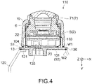
- Fig. 4 is a cross-sectional side view of the camera unit 110
- Fig. 5 is a cross-sectional side view of a primary portion of the camera unit 110.
- the camera unit 110 includes a front case (a first casing) 10, an O-ring 6, an image-capturing component 4, and a rear case 13 (a second casing) in this order in a positive Y-axis direction.
- the image-capturing component 4 includes a lens assembly 7, a shield case 8 used for electromagnetic shielding, a dustproof sheet 9, a board unit 5, a heat dissipating sheet 11, and a spacer cushion 12 in this order in the positive Y-axis direction.
- the board unit 5 includes a front board 2, a spacer board 1, and a rear board 3 in this order in the positive Y-axis direction.
- the front case 10 includes a front surface portion 101 that is formed substantially orthogonal to the front-rear direction (the Y direction), and a lateral surface portion 102 that extends toward the rear case 13 from a peripheral edge of the front surface portion 101.
- the front case 10 accommodates therein the image-capturing component 4.
- the front surface portion 101 is substantially rectangular as viewed from the Y direction.
- the front case 10 is hollow, and includes a space portion that is a region surrounded by the front surface portion 101 and the lateral surface portion 102.
- the front case 10 includes a rectangular opening end 104 in a Z-X plane.
- the opening end 104 and the front surface portion 101 may be formed into any shape, such as a circle or a triangle, in the Z-X plane.
- the rear case 13 is fixed between the front case 10 and the bracket 120.
- the rear case 13 is a shield case used for electromagnetic shielding, and includes a rear surface portion 131 that is arranged substantially orthogonal to the front-rear direction (the Y direction), and a lateral surface portion 132 that extends toward the front case 10 from a peripheral edge of the rear surface portion 131.
- the rear case 13 has a shape similar to a shape of the front surface portion 101, and, in the present embodiment, the rear surface portion 131 is substantially rectangular as viewed from the Y direction.
- a peripheral edge 136 of the rear case 13 is formed to have a larger area than the opening end 104 such that the peripheral edge 136 extends outward on the side of an outer periphery of the opening end 104 of the front case 10 (refer to (B) of Fig. 3 ).
- the rear case 13 is hollow, and includes a space portion that is a region surrounded by the rear surface portion 131 and the lateral surface portion 132.
- the front case 10 and the rear case 13 are typically connected to each other using laser welding, which will be described in detail later. This results in forming an internal space that includes the space portion of the front case 10 and the space portion of the rear case 13.
- the image-capturing component 4 is arranged in the internal space.
- a through-hole 103 is formed in a middle portion of the front surface portion 101 of the front case 10, and a lens portion 71 of the lens assembly 7 is inserted into the through-hole 103 to assemble the lens assembly 7 to the front case 10.
- the image-capturing component 4 is arranged such that an optical axis O for image-capturing passes through substantially the center of the lens assembly 7.
- the front board 2 and the rear board 3 are electrically connected to each other using a B-to-B connection (a connection using a connector) or a flexible connection.
- the spacer board 1 is arranged between the front board 2 and the rear board 3 by, for example, a snap-fit or bonding.
- a solid-state imaging device 22 such as a complementary metal-oxide semiconductor (CMOS) image sensor or a charge coupled device (CCD) image sensor is mounted on the front board 2 as a sensor element.
- CMOS complementary metal-oxide semiconductor
- CCD charge coupled device
- Peripheral circuits such as a drive circuit that drives the solid-state imaging device 22, and a signal processing circuit that processes an output signal from the solid-state imaging device 22 are mounted on each of the front board 2 and the rear board 3.
- a connector 135 is provided to the rear surface portion 131 of the rear case 13.
- the connector 135 is electrically connected to the board unit 5 through a flexible printed circuit (FPC) 23. This results in supplying power from a vehicle body to the image-capturing component 4, or in outputting an image signal from the image-capturing component 4 to the vehicle body.
- FPC flexible printed circuit
- the O-ring 6 is arranged inside the front case 10 all around an inner peripheral surface of the front case 10.
- the O-ring 6 serves to form a seal between the front case 10 and the image-capturing component 4 (the lens assembly 7). This prevents, for example, raindrops from entering the casing through the through-hole 103 of the front case 10.
- Any elastic material such as rubber or plastic may be used as a material of the O-ring 6.
- the rear case 13 is joined to the front case 10 and the bracket 120 using laser welding.
- the front case 10 and the bracket 120 are made of a resin material that has absorptive properties with respect to laser light of a specified wavelength.
- the rear case 13 is made of a resin material that has transmissive properties with respect to the laser light.
- a general-purpose resin such as an acrylonitrile-styrene (AS) resin or an acrylonitrile-butadiene-styrene (ABS) resin, a polycarbonate (PC) resin, a mixture resin of ABS and PC, a polyamide (PA) resin, or a polybutylene terephthalate (PBT) resin is used as a resin material that has absorptive properties or transmissive properties with respect to laser light.
- AS acrylonitrile-styrene
- ABS acrylonitrile-butadiene-styrene
- PC polycarbonate
- PA polyamide
- PBT polybutylene terephthalate
- the absorptive properties or the transmissive properties with respect to laser light can be adjusted by, for example, an amount of a laser-absorptive material that is mixed with a resin.
- a laser-absorptive material for example, carbon black can be used as the laser-absorptive material.
- the adjustment of an amount of the laser-absorptive material added makes it possible to adjust the laser-light absorptance (or the laser-light transmittance) discretionarily. Note that it is favorable that the same type of matrix resin be used for a resin material having absorptive properties with respect to laser light and a resin material having transmissive properties with respect to the laser light. This results in increasing an affinity between resins situated at a joining portion and in enhancing the weld strength.
- a change in a thickness of a resin makes it possible to adjust the transmittance.
- the thickness of a resin is made larger (when a resin is made thicker), this makes it possible to further decrease the transmittance of the resin.
- the thickness of a resin is made smaller (when a resin is made thinner), this makes it possible to further increase the transmittance of the resin.
- red laser light or infrared laser light of a wavelength of from 800 nm to 1100 nm is used as laser light used for welding.
- the transmittance of the resin material with respect to the laser light is greater than or equal to 30%, and favorably greater than or equal to 40%.
- the rear case 13 includes a first surface S1 that faces the opening end 104 of the front case 10, and a second surface S2 that faces the support surface 121 of the bracket 120.
- the support surface 121 is formed into a rectangularly annular, planar shape that faces a portion, in the peripheral edge of the rear case 13, that corresponds to the second surface S2 (refer to Fig. 4 ).
- the first surface S1 of the rear case 13 includes a protrusion 133 that is closely fitted into the opening end 104 of the front case 10.
- the first surface S1 further includes a first welding portion W1 that is welded to the opening end 104 of the front case 10.
- the first welding portion W1 is a melt-and-mixture portion of a resin material of the front case 10 and a resin material of the rear case 13 (indicated by a black circle on the first surface S1 in Fig. 4 ).
- the first welding portion W1 is annularly provided along the entirety of a portion, in the peripheral edge 136 of the rear case 13, that corresponds to the first surface S1 and faces the opening end 104.
- the second surface S2 of the rear case 13 corresponds to the rear surface portion 131 of the rear case 13.
- the second surface S2 includes a second welding portion W2 that is welded to the support surface 121 of the bracket 120.
- the second welding portion W2 is a melt-and-mixture portion of a resin material of the bracket 120 and a resin material of the rear case 13 (indicated by a black circle on the second surface S2 in Fig. 4 ).
- the second welding portion W2 is formed on a protrusion 137 (a first convex surface portion) that protrudes toward the support surface 121 of the bracket 120 from the second surface S2 of the rear case 13.
- the protrusion 137 is rectangularly annularly formed along the periphery (the peripheral edge 136) of the rear case 13, and a protrusion end surface of the protrusion 137 is a planar surface parallel to the support surface 121.
- the second welding portion W2 is annularly formed on the protrusion 137 by the protrusion 137 being welded to the support surface 121 using laser welding.
- Fig. 6 is a schematic plan view of the camera unit 110 that illustrates a relationship between the first welding portion W1 and the second welding portion W2.
- the first welding portion W1 and the second welding portion W2 are rectangularly annularly formed, with an optical axis of the camera unit 110 passing through the centers of the first welding portion W1 and the second welding portion W2, as illustrated in the figure.
- the first welding portion W1 and the second welding portion W2 are not formed in the same location as viewed from a direction of the optical axis, and the second welding portion W2 is formed on the side of an outer periphery of the first welding portion W1.
- first welding portion W1 and the second welding portion W2 are each annually continuously formed, sealing properties of the joining portion between the front case 10 and the rear case 13 and of the joining portion between the rear case 13 and the bracket 120 are improved, and this results in ensuring waterproof properties and dustproof properties.
- a method for producing a sensor module according to the present embodiment includes accommodating the camera unit 4 including a sensor element (the solid-state imaging device 22) in the front case 10, joining the first surface S1 of the rear case 13 to the opening end 104 of the front case 10 using laser welding, and joining the bracket 120 to the second surface S2 of the rear case 13 using laser welding.
- FIG. 7 are schematic process diagrams used to describe the method for producing the sensor module 100.
- the image-capturing component 4 obtained by sequentially assembling the shield case 8, the dustproof sheet 9, the board unit 5, the heat dissipating sheet 11, and the spacer cushion 12 to the lens assembly 7 in a Y-axis direction is accommodated in the front case 10 through the seal ring 6. Then, as illustrated in (A) of Fig. 7 , the front case 10 and the rear case 13 are assembled to each other in the Y-axis direction such that the opening end 104 of the front case 10 and the first surface S1 of the rear case 13 face each other.
- laser light L used for welding is irradiated onto the second surface S2 of the rear case 13 in a state in which the rear case 13 is pressed against the front case 10 under a specified load, as illustrated in (B) of Fig. 7 .
- An irradiation direction is a direction of an arrow of the laser light L in (A) of Fig. 7 .
- the laser light L is transmitted through a resin layer of the rear case 13 to be irradiated onto a portion, in the front case 10, that corresponds to the opening end 104, and is rectangularly annularly scanned over the second surface S2 of the rear case 13 along the opening end 104.
- the laser light L may be pulsed light or continuous light.
- the front case 10 is made of a resin material that has absorptive properties with respect to the laser light L
- the rear case 13 is made of a resin material that has transmissive properties with respect to the laser light L.
- the laser light L is transmitted through the rear case 13 to be irradiated onto the opening end 104 of the front case 10.
- a region, in the opening end 104, that is irradiated with the laser light L generates heat due to absorption of the laser light L to be partially melted.
- the first surface S1 being included in the rear case 13 and facing the opening end 104 is also partially melted due to heat transfer from a melted portion of the opening end 104.
- the melted portion of the front case 10 and a melted portion of the rear case 13 are cooled to be solidified, and the first welding portion W1 welded to the opening end 104 of the front case 10 is formed on the first surface S1 of the rear case 13. This results in producing the camera unit 110 obtained by the front case 10 and the rear case 13 being integrally joined to each other.
- the camera unit 110 is turned upside down, and the camera unit 110 and the bracket 120 are assembled to each other in the Y-axis direction such that the second surface S2 of the rear case 13 faces the support surface 121 of the bracket 120.
- the laser light L used for welding is irradiated onto the first surface S1 of the rear case 13 of the camera unit 110 in a state in which the rear case 13 is pressed against the bracket 120 under a specified load.
- An irradiation direction is a direction of an arrow of the laser light L in (B) of Fig. 7 .
- the laser light L is transmitted through the resin layer of the rear case 13 to be irradiated onto a portion, in the rear case 13, that corresponds to the protrusion 137 (refer to (A) of Fig. 3 and Fig. 5 ), and is rectangularly annularly scanned over the first surface S1 of the rear case 13 along the protrusion 137.
- the laser light L may be pulsed light or continuous light.
- the bracket 120 is made of a resin material that has absorptive properties with respect to the laser light L, as in the case of the front case 10.
- the laser light L is transmitted through the rear case 13 to be irradiated onto the support surface 121 of the bracket 120.
- a region, in the support surface 121, that is irradiated with the laser light L generates heat due to absorption of the laser light L to be partially melted.
- the protrusion 137 being included in the rear case 13 and facing the support surface 121 is also partially melted due to heat transfer from a melted portion of the support surface 121.
- the rear case 13 is welded to the front case 10 and the bracket 120 by laser welding.
- the present embodiment there is no need to provide a space for a screw hollow and to perform attachment with a screw for packing, compared to when a rear case and a front case are joined to each other using a screw.
- This makes it possible to improve a degree of freedom in design, to facilitate the operation, and to reduce costs by reducing the number of screw components.
- the sensor module 100 can be made smaller in size since there is no need for a space for a screw hollow.
- a high-functionality large component (LSI) can be implemented since the internal space of the sensor module 100 is made larger. This makes it possible to raise the functionality of the sensor module 100.
- LSI high-functionality large component
- the rear case 13 is formed to have a larger area than the opening end 104 of the front case 10, and the second welding portion W2 is provided on the side of the outer periphery of the first welding portion W1. Consequently, even after the first welding portion W1 is formed (after the front case 10 and the rear case 13 are welded to each other), the laser light L can be irradiated onto the peripheral edge 136 that is included in the rear case 13 and on which the second welding portion W2 is formed. This results in being able to stably form the second welding portion W2.
- FIG. 8 are perspective views illustrating other examples of a configuration of the camera unit 110 as viewed from the side of the rear case 13.
- Camera units 110A and 110B respectively illustrated in (A) and (B) of Fig. 8 each have the second welding portion W2 different from the second welding portion W2 of the embodiment described above. Note that an illustration of the bracket 120 is omitted.
- the second welding portion W2 is formed in an elevated portion 138 (the first convex surface portion) that is further formed on the protrusion 137 on the second surface S2 of the rear case 13.
- the elevated portion 138 is a convex surface of a specified height, the convex surface protruding toward the bracket 120 from a surface of the protrusion 137 and being welded to the bracket 120.
- the elevated portion 138 is provided at a plurality of positions around the second surface S (the peripheral edge 136).
- the elevated portion 138 is formed at positions (two positions), on the second surface S2, that are situated diagonal to each other. However, the elevated portion 138 may be formed at three or more positions situated at corners of the second surface S2.
- the elevated portion 138 is formed on the protrusion 137 in the illustrated example. However, the protrusion 137 may be omitted. In this case, the elevated portion 138 is directly formed on the second surface S2.
- the welding portion W2 is locally formed at a position at which the elevated portion 138 is formed.
- Such a configuration can be applied to, for example, a camera module in which there is no need for hermetic sealing between the camera unit 110A and the bracket 120.
- This example makes it possible to, for example, simplify the configuration of a joining portion between the camera unit 110A and the bracket 120 and to facilitate the joining operation.
- hermetic sealing of the camera unit can be enhanced by using packing.
- the camera unit 110A more hermetically sealed by using packing can be used as a camera module in which there is a need for hermetic sealing.
- the second welding portion W2 is formed in four wing portions 139 (the first convex surface portions) formed at the four corners of the second surface S2 of the rear case 13.
- the rear case 13 is formed to have substantially the same size (area) as the opening end 104 of the front case 10, and a plurality of wing portions 139 is formed such that each of the plurality of wing portions 139 protrudes outward on the side of an outer periphery of the second surface S2 from a corresponding one of the four corners of the second surface S2.
- Each of the plurality of wing portions 139 is a convex surface of a specified height, the convex surface protruding toward the bracket 120 from the second surface S2 and being welded to the bracket 120.
- the second welding portion W2 is formed on a surface (an end surface) of the wing portion 139 that is situated on the side of the bracket 120.
- the rear case 13 includes a plurality of convex portions 140 (second convex surface portions).
- Each of the plurality of convex portions 140 is provided on the second surface S2 on the side of an inner periphery of the wing portion 139.
- Each of the plurality of convex portions 140 is formed to protrude toward the bracket 120 to a lesser extent than the wing portion 139.
- the plurality of convex portions 140 serves as a stopper that defines a relative position between the rear case 13 and the bracket when the wing portion 139 and the bracket 120 are welded to each other.
- the rear case 13 is pressed against the bracket 120 under a specified load when the rear case 13 is welded to the bracket 120.
- the wing portion 139 is melted due to irradiation of the laser light L.
- a distance between the L rear case 13 (the second surface S2) and the bracket 120 (the support surface 121) is gradually shortened during the irradiation of the laser light.
- the convex portion 140 protruding to a lesser extent than the wing portion 139 is provided at a specified position on the second surface S2, this makes it possible to limit an approaching distance between the rear case 13 and the bracket 120 to an amount of protrusion of the convex portion 140 due to the convex portion 140 being brought into contact with the bracket 120 (the support surface 121).
- a position at which the convex portion 140 is formed, the number of the convex portions 140, a shape of the convex portion 140, and the like are not particularly limited, and can be set discretionarily.
- Effects similar to those described above can also be provided by the camera unit 110A having the configuration above.
- a specified relative distance between the camera unit 110B and the bracket 120 can be stably ensured.
- variations in optical axis can be reduced after the assembly of the sensor module.
- the front case 10 and the bracket 120 are made of a resin material that has absorptive properties with respect to the laser light L
- the rear case 13 is made of a resin material that has transmissive properties with respect to the laser light L
- the front case 10, the bracket 120, and the rear case 13 are not limited thereto.
- the front case 10 and the bracket 120 may be made of a resin material that has transmissive properties with respect to the laser light L
- the rear case 13 may be made of a resin material that has absorptive properties with respect to the laser light L.
- a flange 104F that extends outward is formed at the opening end of the front case 10, and the laser light L is irradiated onto the flange 104F to form the first welding portion W1 between the flange 104F and a portion, in the peripheral edge of the rear case 13, that corresponds to the first surface S1, for example, as schematically illustrated in Fig. 9 .
- the laser light L is irradiated onto a portion, in the bracket 120, that is situated opposite to the support surface 121 to form the second welding portion W2 between a portion, in the peripheral edge of the rear case 13, that corresponds to the second surface S2 and the support surface 121 of the bracket 120.
- the second welding portion W2 is formed on the side of an inner periphery of the first welding portion W1.
- the second welding portion W2 may be formed on the side of an outer periphery of the first welding portion W1.
- the technology according to the present disclosure can be applied to various products.
- the technology according to the present disclosure may be provided as a sensor module that is mounted on one of the types of mobile bodies such as vehicle, electric vehicle, hybrid electric vehicle, motorcycle, bicycle, personal mobility, airplane, drone, ship, robot, construction machinery, and agricultural machinery (tractor).
- a camera module has been described as an example of the sensor module 100 in the embodiments described above.
- the present technology is not limited thereto.
- the present technology can also be adopted for a sensor module that includes, as a sensor element, a ranging sensor such as light detection and ranging (LiDAR) or a time-of-flight (ToF) sensor.
- a ranging sensor such as light detection and ranging (LiDAR) or a time-of-flight (ToF) sensor.
- the front case 10 and the rear case 13 are welded to each other by laser welding, and the rear case 13 and the bracket 120 are welded to each other by laser welding.
- the present technology can also be applied when another welding method such as ultrasonic welding is used.
Landscapes
- Engineering & Computer Science (AREA)
- Physics & Mathematics (AREA)
- General Physics & Mathematics (AREA)
- Multimedia (AREA)
- Signal Processing (AREA)
- Computer Networks & Wireless Communication (AREA)
- Radar, Positioning & Navigation (AREA)
- Remote Sensing (AREA)
- Studio Devices (AREA)
- Lining Or Joining Of Plastics Or The Like (AREA)
Abstract
Description
- The present technology relates to a sensor module mounted on, for example, a vehicle, and a method for producing the sensor module.
- A conventional camera unit used by being mounted on a vehicle is fastened by screwing to be fixed to a bracket attached to a vehicle body (for example, Patent Literature 1). Further, packing is put between the camera unit and the bracket in order to prevent water from entering a vehicle, depending on the model of vehicle or the model of camera unit.
- Patent Literature 1:
Japanese Patent Application Laid-open No. 2018-202976 - In the case of the conventional camera unit described above, there is a need to provide a space for a screw hollow and to perform attachment with a screw for packing. It is desirable that no space for a screw hollow be provided to increase a degree of freedom in design, fastening with a screw for packing not be performed to facilitate the operation (to improve the productivity), and production costs be reduced.
- In view of the circumstances described above, it is an object of the present technology to provide a sensor module and a method for producing the sensor module, the sensor module making it possible to improve a degree of freedom in design, to facilitate the operation, and to reduce costs by reducing the number of components.
- In order to achieve the object described above, a sensor module according to an embodiment of the present technology includes a sensor element, a first casing, a bracket, and a second casing. The first casing includes an opening end and accommodates therein the sensor element. The bracket fixes the first casing to an attachment target. The second casing includes a first surface that includes a first welding portion welded to the opening end, and a second surface that includes a second welding portion welded to the bracket, the second casing being fixed between the first casing and the bracket.
- In the sensor module, the second casing is welded to the first casing and the bracket. This results in there being no need to provide a space for a screw hollow and to perform attachment with a screw for packing. This makes it possible to improve a degree of freedom in design, to facilitate the operation, and to reduce costs by reducing the number of components.
- The first welding portion may be annularly provided along a portion, in a peripheral edge of the second casing, that is situated on the first surface, and the second welding portion may be annularly provided on a portion, in the peripheral edge, that is situated on the second surface on a side of an outer periphery of the first welding portion.
- The second casing may further include a first convex surface portion that protrudes toward the bracket from the second surface to form the second welding portion.
- The second casing may further include a plurality of second convex surface portions each provided on the second surface on a side of an inner periphery of the first convex surface portion, the plurality of second convex surface portions being capable of being brought into contact with the bracket.
- The first convex surface portion may be annularly formed around the second surface. Alternatively, the first convex surface portion may be formed at a plurality of positions around the second surface.
- The first casing and the bracket may be made of a resin material that has absorptive properties with respect to laser light of a specified wavelength, and the second casing may be made of a resin material that has transmissive properties with respect to the laser light.
- The first casing and the bracket may be made of a resin material that has transmissive properties with respect to laser light of a specified wavelength, and the second casing may be made of a resin material that has absorptive properties with respect to the laser light.
- The sensor element may be a solid-state imaging device.
- The sensor element may be a ranging sensor.
- A method for producing a sensor module according to an embodiment of the present technology includes accommodating a sensor element in a first casing; joining a first surface of a second casing to an opening end of the first casing using laser welding; and joining a bracket to a second surface of the second casing using the laser welding.
-
- [
Fig. 1] Fig. 1 is a side view of a sensor module according to an embodiment of the present technology. - [
Fig. 2] Fig. 2 is an exploded perspective view of a camera unit in the sensor module. - [
Fig. 3] Fig. 3 is a set of overall perspective views of the camera unit. - [
Fig. 4] Fig. 4 is a cross-sectional side view of the camera unit. - [
Fig. 5] Fig. 5 is a cross-sectional view of a primary portion of the camera unit. - [
Fig. 6] Fig. 6 is a schematic plan view of the camera unit that illustrates a relationship between a first welding portion and a second welding portion. - [
Fig. 7] Fig. 7 is a set of schematic process diagrams used to describe a method for producing the sensor module. - [
Fig. 8] Fig. 8 is a set of perspective views illustrating other examples of a configuration of the camera unit. - [
Fig. 9] Fig. 9 schematically illustrates a modification of a configuration of the sensor module. Mode(s) for Carrying Out the Invention - Embodiments according to the present technology will now be described below with reference to the drawings.
-
Fig. 1 is a side view of a sensor module according to an embodiment of the present technology. Asensor module 100 of the present embodiment is a camera module used by being mounted on a vehicle. - In the following description, a right-and-left direction, a front-rear direction (an optical-axis direction), and a height direction of the
sensor module 100 are respectively set to be a Z direction, a Y direction, and an X direction. Of course, such a setting of the direction is not limitative. - The
sensor module 100 includes acamera unit 110 and abracket 120. For example, thecamera unit 110 is arranged outside of a vehicle body (an attachment target) (not illustrated), and internally includes an image-capturing component that captures an image of a region situated ahead of a vehicle, an image of a region situated behind the vehicle, or a region on a lateral side of the vehicle depending on an attachment position. For example, a camera attached to a front portion (for example, a radiator grill) of a vehicle body captures an image of an environment ahead of the vehicle. Further, the camera attached to a rear portion (for example, above a license plate) of the vehicle body captures an image of an environment behind the vehicle. Furthermore, the camera attached to a side portion of the vehicle (for example, an upper portion of a pillar (an A-pillar, a B-pillar, or a pillar (a C-pillar, a D-pillar) situated in the rear of the vehicle, or a sideview mirror) captures an image of an environment in a lateral direction of the vehicle. - The
bracket 120 is a fixation member used to fix thecamera unit 110 to a vehicle body. Thebracket 120 includes asupport surface 121 that supports thecamera unit 110. As will be described later, thecamera unit 110 is joined to thesupport surface 121 of thebracket 120 using laser welding. -
Fig. 2 is an exploded perspective view of thecamera unit 110, (A) and (B) ofFig. 3 are overall perspective views of thecamera unit 110,Fig. 4 is a cross-sectional side view of thecamera unit 110, andFig. 5 is a cross-sectional side view of a primary portion of thecamera unit 110. - The
camera unit 110 includes a front case (a first casing) 10, an O-ring 6, an image-capturingcomponent 4, and a rear case 13 (a second casing) in this order in a positive Y-axis direction. - The image-
capturing component 4 includes alens assembly 7, ashield case 8 used for electromagnetic shielding, adustproof sheet 9, aboard unit 5, aheat dissipating sheet 11, and aspacer cushion 12 in this order in the positive Y-axis direction. Theboard unit 5 includes afront board 2, aspacer board 1, and arear board 3 in this order in the positive Y-axis direction. - The
front case 10 includes afront surface portion 101 that is formed substantially orthogonal to the front-rear direction (the Y direction), and alateral surface portion 102 that extends toward therear case 13 from a peripheral edge of thefront surface portion 101. Thefront case 10 accommodates therein the image-capturingcomponent 4. - In the present embodiment, the
front surface portion 101 is substantially rectangular as viewed from the Y direction. Thefront case 10 is hollow, and includes a space portion that is a region surrounded by thefront surface portion 101 and thelateral surface portion 102. At an end of thelateral surface portion 102 that is situated on the side of therear case 13, thefront case 10 includes arectangular opening end 104 in a Z-X plane. Theopening end 104 and thefront surface portion 101 may be formed into any shape, such as a circle or a triangle, in the Z-X plane. - The
rear case 13 is fixed between thefront case 10 and thebracket 120. Therear case 13 is a shield case used for electromagnetic shielding, and includes arear surface portion 131 that is arranged substantially orthogonal to the front-rear direction (the Y direction), and alateral surface portion 132 that extends toward thefront case 10 from a peripheral edge of therear surface portion 131. Therear case 13 has a shape similar to a shape of thefront surface portion 101, and, in the present embodiment, therear surface portion 131 is substantially rectangular as viewed from the Y direction. Aperipheral edge 136 of therear case 13 is formed to have a larger area than the openingend 104 such that theperipheral edge 136 extends outward on the side of an outer periphery of the openingend 104 of the front case 10 (refer to (B) ofFig. 3 ). Therear case 13 is hollow, and includes a space portion that is a region surrounded by therear surface portion 131 and thelateral surface portion 132. - The
front case 10 and therear case 13 are typically connected to each other using laser welding, which will be described in detail later. This results in forming an internal space that includes the space portion of thefront case 10 and the space portion of therear case 13. The image-capturingcomponent 4 is arranged in the internal space. - As illustrated in
Fig. 2 , a through-hole 103 is formed in a middle portion of thefront surface portion 101 of thefront case 10, and alens portion 71 of thelens assembly 7 is inserted into the through-hole 103 to assemble thelens assembly 7 to thefront case 10. The image-capturingcomponent 4 is arranged such that an optical axis O for image-capturing passes through substantially the center of thelens assembly 7. - The
front board 2 and therear board 3 are electrically connected to each other using a B-to-B connection (a connection using a connector) or a flexible connection. Upon making this connection, thespacer board 1 is arranged between thefront board 2 and therear board 3 by, for example, a snap-fit or bonding. A solid-state imaging device 22 such as a complementary metal-oxide semiconductor (CMOS) image sensor or a charge coupled device (CCD) image sensor is mounted on thefront board 2 as a sensor element. The solid-state imaging device 22 captures an image of subject light through thelens assembly 7. Peripheral circuits such as a drive circuit that drives the solid-state imaging device 22, and a signal processing circuit that processes an output signal from the solid-state imaging device 22 are mounted on each of thefront board 2 and therear board 3. - A
connector 135 is provided to therear surface portion 131 of therear case 13. For example, theconnector 135 is electrically connected to theboard unit 5 through a flexible printed circuit (FPC) 23. This results in supplying power from a vehicle body to the image-capturingcomponent 4, or in outputting an image signal from the image-capturingcomponent 4 to the vehicle body. - The O-
ring 6 is arranged inside thefront case 10 all around an inner peripheral surface of thefront case 10. The O-ring 6 serves to form a seal between thefront case 10 and the image-capturing component 4 (the lens assembly 7). This prevents, for example, raindrops from entering the casing through the through-hole 103 of thefront case 10. Any elastic material such as rubber or plastic may be used as a material of the O-ring 6. - In the present embodiment, the
rear case 13 is joined to thefront case 10 and thebracket 120 using laser welding. In order to weld therear case 13 to thefront case 10 and thebracket 120 using laser welding, thefront case 10 and thebracket 120 are made of a resin material that has absorptive properties with respect to laser light of a specified wavelength. Further, therear case 13 is made of a resin material that has transmissive properties with respect to the laser light. - For example, a general-purpose resin such as an acrylonitrile-styrene (AS) resin or an acrylonitrile-butadiene-styrene (ABS) resin, a polycarbonate (PC) resin, a mixture resin of ABS and PC, a polyamide (PA) resin, or a polybutylene terephthalate (PBT) resin is used as a resin material that has absorptive properties or transmissive properties with respect to laser light.
- The absorptive properties or the transmissive properties with respect to laser light can be adjusted by, for example, an amount of a laser-absorptive material that is mixed with a resin. For example, carbon black can be used as the laser-absorptive material. The adjustment of an amount of the laser-absorptive material added makes it possible to adjust the laser-light absorptance (or the laser-light transmittance) discretionarily. Note that it is favorable that the same type of matrix resin be used for a resin material having absorptive properties with respect to laser light and a resin material having transmissive properties with respect to the laser light. This results in increasing an affinity between resins situated at a joining portion and in enhancing the weld strength. Further, a change in a thickness of a resin makes it possible to adjust the transmittance. When the thickness of a resin is made larger (when a resin is made thicker), this makes it possible to further decrease the transmittance of the resin. Further, when the thickness of a resin is made smaller (when a resin is made thinner), this makes it possible to further increase the transmittance of the resin.
- In the present embodiment, for example, red laser light or infrared laser light of a wavelength of from 800 nm to 1100 nm is used as laser light used for welding. With respect to a resin material having transmissive properties with respect to laser light, the transmittance of the resin material with respect to the laser light is greater than or equal to 30%, and favorably greater than or equal to 40%.
- As illustrated in
Fig. 4 , therear case 13 includes a first surface S1 that faces the openingend 104 of thefront case 10, and a second surface S2 that faces thesupport surface 121 of thebracket 120. Thesupport surface 121 is formed into a rectangularly annular, planar shape that faces a portion, in the peripheral edge of therear case 13, that corresponds to the second surface S2 (refer toFig. 4 ). - The first surface S1 of the
rear case 13 includes aprotrusion 133 that is closely fitted into the openingend 104 of thefront case 10. The first surface S1 further includes a first welding portion W1 that is welded to the openingend 104 of thefront case 10. The first welding portion W1 is a melt-and-mixture portion of a resin material of thefront case 10 and a resin material of the rear case 13 (indicated by a black circle on the first surface S1 inFig. 4 ). The first welding portion W1 is annularly provided along the entirety of a portion, in theperipheral edge 136 of therear case 13, that corresponds to the first surface S1 and faces the openingend 104. - The second surface S2 of the
rear case 13 corresponds to therear surface portion 131 of therear case 13. The second surface S2 includes a second welding portion W2 that is welded to thesupport surface 121 of thebracket 120. The second welding portion W2 is a melt-and-mixture portion of a resin material of thebracket 120 and a resin material of the rear case 13 (indicated by a black circle on the second surface S2 inFig. 4 ). As illustrated in (A) ofFig. 3 andFig. 5 , the second welding portion W2 is formed on a protrusion 137 (a first convex surface portion) that protrudes toward thesupport surface 121 of thebracket 120 from the second surface S2 of therear case 13. Theprotrusion 137 is rectangularly annularly formed along the periphery (the peripheral edge 136) of therear case 13, and a protrusion end surface of theprotrusion 137 is a planar surface parallel to thesupport surface 121. The second welding portion W2 is annularly formed on theprotrusion 137 by theprotrusion 137 being welded to thesupport surface 121 using laser welding. -
Fig. 6 is a schematic plan view of thecamera unit 110 that illustrates a relationship between the first welding portion W1 and the second welding portion W2. In the Z-X plane, the first welding portion W1 and the second welding portion W2 are rectangularly annularly formed, with an optical axis of thecamera unit 110 passing through the centers of the first welding portion W1 and the second welding portion W2, as illustrated in the figure. The first welding portion W1 and the second welding portion W2 are not formed in the same location as viewed from a direction of the optical axis, and the second welding portion W2 is formed on the side of an outer periphery of the first welding portion W1. Since the first welding portion W1 and the second welding portion W2 are each annually continuously formed, sealing properties of the joining portion between thefront case 10 and therear case 13 and of the joining portion between therear case 13 and thebracket 120 are improved, and this results in ensuring waterproof properties and dustproof properties. - Next, a method for producing the
sensor module 100 having the configuration described above is described. - A method for producing a sensor module according to the present embodiment includes accommodating the
camera unit 4 including a sensor element (the solid-state imaging device 22) in thefront case 10, joining the first surface S1 of therear case 13 to the openingend 104 of thefront case 10 using laser welding, and joining thebracket 120 to the second surface S2 of therear case 13 using laser welding. - (A) and (B) of
Fig. 7 are schematic process diagrams used to describe the method for producing thesensor module 100. - First, as illustrated in
Fig. 2 , the image-capturingcomponent 4 obtained by sequentially assembling theshield case 8, thedustproof sheet 9, theboard unit 5, theheat dissipating sheet 11, and thespacer cushion 12 to thelens assembly 7 in a Y-axis direction is accommodated in thefront case 10 through theseal ring 6. Then, as illustrated in (A) ofFig. 7 , thefront case 10 and therear case 13 are assembled to each other in the Y-axis direction such that the openingend 104 of thefront case 10 and the first surface S1 of therear case 13 face each other. - Thereafter, laser light L used for welding is irradiated onto the second surface S2 of the
rear case 13 in a state in which therear case 13 is pressed against thefront case 10 under a specified load, as illustrated in (B) ofFig. 7 . An irradiation direction is a direction of an arrow of the laser light L in (A) ofFig. 7 . Here, the laser light L is transmitted through a resin layer of therear case 13 to be irradiated onto a portion, in thefront case 10, that corresponds to the openingend 104, and is rectangularly annularly scanned over the second surface S2 of therear case 13 along the openingend 104. The laser light L may be pulsed light or continuous light. - In the present embodiment, the
front case 10 is made of a resin material that has absorptive properties with respect to the laser light L, and therear case 13 is made of a resin material that has transmissive properties with respect to the laser light L. Thus, the laser light L is transmitted through therear case 13 to be irradiated onto the openingend 104 of thefront case 10. A region, in the openingend 104, that is irradiated with the laser light L generates heat due to absorption of the laser light L to be partially melted. On the other hand, the first surface S1 being included in therear case 13 and facing the openingend 104 is also partially melted due to heat transfer from a melted portion of the openingend 104. Thereafter, the melted portion of thefront case 10 and a melted portion of therear case 13 are cooled to be solidified, and the first welding portion W1 welded to the openingend 104 of thefront case 10 is formed on the first surface S1 of therear case 13. This results in producing thecamera unit 110 obtained by thefront case 10 and therear case 13 being integrally joined to each other. - Next, as illustrated in (B) of
Fig. 7 , thecamera unit 110 is turned upside down, and thecamera unit 110 and thebracket 120 are assembled to each other in the Y-axis direction such that the second surface S2 of therear case 13 faces thesupport surface 121 of thebracket 120. Thereafter, the laser light L used for welding is irradiated onto the first surface S1 of therear case 13 of thecamera unit 110 in a state in which therear case 13 is pressed against thebracket 120 under a specified load. An irradiation direction is a direction of an arrow of the laser light L in (B) ofFig. 7 . Here, the laser light L is transmitted through the resin layer of therear case 13 to be irradiated onto a portion, in therear case 13, that corresponds to the protrusion 137 (refer to (A) ofFig. 3 andFig. 5 ), and is rectangularly annularly scanned over the first surface S1 of therear case 13 along theprotrusion 137. The laser light L may be pulsed light or continuous light. - In the present embodiment, the
bracket 120 is made of a resin material that has absorptive properties with respect to the laser light L, as in the case of thefront case 10. Thus, the laser light L is transmitted through therear case 13 to be irradiated onto thesupport surface 121 of thebracket 120. A region, in thesupport surface 121, that is irradiated with the laser light L generates heat due to absorption of the laser light L to be partially melted. On the other hand, theprotrusion 137 being included in therear case 13 and facing thesupport surface 121 is also partially melted due to heat transfer from a melted portion of thesupport surface 121. Thereafter, the melted portion of thebracket 120 and a melted portion of therear case 13 are cooled to be solidified, and the second welding portion W2 welded to thesupport surface 121 of thebracket 120 is formed on the second surface S2 of therear case 13. This results in producing thesensor module 100 obtained by thecamera unit 110 and thebracket 120 being integrally joined to each other. - As described above, the
rear case 13 is welded to thefront case 10 and thebracket 120 by laser welding. Thus, according to the present embodiment, there is no need to provide a space for a screw hollow and to perform attachment with a screw for packing, compared to when a rear case and a front case are joined to each other using a screw. This makes it possible to improve a degree of freedom in design, to facilitate the operation, and to reduce costs by reducing the number of screw components. Further, thesensor module 100 can be made smaller in size since there is no need for a space for a screw hollow. Furthermore, a high-functionality large component (LSI) can be implemented since the internal space of thesensor module 100 is made larger. This makes it possible to raise the functionality of thesensor module 100. - Further, according to the present embodiment, the
rear case 13 is formed to have a larger area than the openingend 104 of thefront case 10, and the second welding portion W2 is provided on the side of the outer periphery of the first welding portion W1. Consequently, even after the first welding portion W1 is formed (after thefront case 10 and therear case 13 are welded to each other), the laser light L can be irradiated onto theperipheral edge 136 that is included in therear case 13 and on which the second welding portion W2 is formed. This results in being able to stably form the second welding portion W2. - (A) and (B) of
Fig. 8 are perspective views illustrating other examples of a configuration of thecamera unit 110 as viewed from the side of therear case 13.Camera units Fig. 8 each have the second welding portion W2 different from the second welding portion W2 of the embodiment described above. Note that an illustration of thebracket 120 is omitted. - In the
camera unit 110A illustrated in (A) ofFig. 8 , the second welding portion W2 is formed in an elevated portion 138 (the first convex surface portion) that is further formed on theprotrusion 137 on the second surface S2 of therear case 13. Theelevated portion 138 is a convex surface of a specified height, the convex surface protruding toward thebracket 120 from a surface of theprotrusion 137 and being welded to thebracket 120. Theelevated portion 138 is provided at a plurality of positions around the second surface S (the peripheral edge 136). Theelevated portion 138 is formed at positions (two positions), on the second surface S2, that are situated diagonal to each other. However, theelevated portion 138 may be formed at three or more positions situated at corners of the second surface S2. Further, theelevated portion 138 is formed on theprotrusion 137 in the illustrated example. However, theprotrusion 137 may be omitted. In this case, theelevated portion 138 is directly formed on the second surface S2. - In the
camera unit 110A having the configuration described above, the welding portion W2 is locally formed at a position at which theelevated portion 138 is formed. Such a configuration can be applied to, for example, a camera module in which there is no need for hermetic sealing between thecamera unit 110A and thebracket 120. This example makes it possible to, for example, simplify the configuration of a joining portion between thecamera unit 110A and thebracket 120 and to facilitate the joining operation. Of course, even in a structure in which the welding portion W2 is locally formed at a position at which theelevated portion 138 is formed, hermetic sealing of the camera unit can be enhanced by using packing. Thecamera unit 110A more hermetically sealed by using packing can be used as a camera module in which there is a need for hermetic sealing. - On the other hand, in the
camera unit 110B illustrated in (B) ofFig. 8 , the second welding portion W2 is formed in four wing portions 139 (the first convex surface portions) formed at the four corners of the second surface S2 of therear case 13. In this example, therear case 13 is formed to have substantially the same size (area) as the openingend 104 of thefront case 10, and a plurality ofwing portions 139 is formed such that each of the plurality ofwing portions 139 protrudes outward on the side of an outer periphery of the second surface S2 from a corresponding one of the four corners of the second surface S2. Each of the plurality ofwing portions 139 is a convex surface of a specified height, the convex surface protruding toward thebracket 120 from the second surface S2 and being welded to thebracket 120. The second welding portion W2 is formed on a surface (an end surface) of thewing portion 139 that is situated on the side of thebracket 120. - Further, in the
camera unit 110B, therear case 13 includes a plurality of convex portions 140 (second convex surface portions). Each of the plurality ofconvex portions 140 is provided on the second surface S2 on the side of an inner periphery of thewing portion 139. Each of the plurality ofconvex portions 140 is formed to protrude toward thebracket 120 to a lesser extent than thewing portion 139. The plurality ofconvex portions 140 serves as a stopper that defines a relative position between therear case 13 and the bracket when thewing portion 139 and thebracket 120 are welded to each other. - In other words, the
rear case 13 is pressed against thebracket 120 under a specified load when therear case 13 is welded to thebracket 120. Here, thewing portion 139 is melted due to irradiation of the laser light L. Thus, a distance between the L rear case 13 (the second surface S2) and the bracket 120 (the support surface 121) is gradually shortened during the irradiation of the laser light. Thus, when theconvex portion 140 protruding to a lesser extent than thewing portion 139 is provided at a specified position on the second surface S2, this makes it possible to limit an approaching distance between therear case 13 and thebracket 120 to an amount of protrusion of theconvex portion 140 due to theconvex portion 140 being brought into contact with the bracket 120 (the support surface 121). A position at which theconvex portion 140 is formed, the number of theconvex portions 140, a shape of theconvex portion 140, and the like are not particularly limited, and can be set discretionarily. - Effects similar to those described above can also be provided by the
camera unit 110A having the configuration above. In particular, in this example, a specified relative distance between thecamera unit 110B and thebracket 120 can be stably ensured. Thus, for example, variations in optical axis can be reduced after the assembly of the sensor module. - In the embodiments described above, the
front case 10 and thebracket 120 are made of a resin material that has absorptive properties with respect to the laser light L, and therear case 13 is made of a resin material that has transmissive properties with respect to the laser light L. However, thefront case 10, thebracket 120, and therear case 13 are not limited thereto. For example, thefront case 10 and thebracket 120 may be made of a resin material that has transmissive properties with respect to the laser light L, and therear case 13 may be made of a resin material that has absorptive properties with respect to the laser light L. - In this case, a
flange 104F that extends outward is formed at the opening end of thefront case 10, and the laser light L is irradiated onto theflange 104F to form the first welding portion W1 between theflange 104F and a portion, in the peripheral edge of therear case 13, that corresponds to the first surface S1, for example, as schematically illustrated inFig. 9 . Further, the laser light L is irradiated onto a portion, in thebracket 120, that is situated opposite to thesupport surface 121 to form the second welding portion W2 between a portion, in the peripheral edge of therear case 13, that corresponds to the second surface S2 and thesupport surface 121 of thebracket 120. In this example, the second welding portion W2 is formed on the side of an inner periphery of the first welding portion W1. However, the second welding portion W2 may be formed on the side of an outer periphery of the first welding portion W1. - The technology according to the present disclosure can be applied to various products. For example, the technology according to the present disclosure may be provided as a sensor module that is mounted on one of the types of mobile bodies such as vehicle, electric vehicle, hybrid electric vehicle, motorcycle, bicycle, personal mobility, airplane, drone, ship, robot, construction machinery, and agricultural machinery (tractor).
- Further, a camera module has been described as an example of the
sensor module 100 in the embodiments described above. However, the present technology is not limited thereto. For example, the present technology can also be adopted for a sensor module that includes, as a sensor element, a ranging sensor such as light detection and ranging (LiDAR) or a time-of-flight (ToF) sensor. - Furthermore, in the embodiments described above, the
front case 10 and therear case 13 are welded to each other by laser welding, and therear case 13 and thebracket 120 are welded to each other by laser welding. However, the present technology can also be applied when another welding method such as ultrasonic welding is used. - The respective configurations of the sensor module, the front case, the rear case, the packing, and the like described with reference to the respective figures are merely embodiments, and any modifications may be made thereto without departing from the spirit of the present technology. In other words, any other configurations for purpose of practicing the present technology may be adopted.
- Note that the present technology may also take the following configurations.
- (1) A sensor module, including:
- a sensor element;
- a first casing that includes an opening end and accommodates therein the sensor element;
- a bracket that fixes the first casing to an attachment target; and
- a second casing that includes a first surface that includes a first welding portion welded to the opening end, and a second surface that includes a second welding portion welded to the bracket, the second casing being fixed between the first casing and the bracket.
- (2) The sensor module according to (1), in which
- the first welding portion is annularly provided along a portion, in a peripheral edge of the second casing, that is situated on the first surface, and
- the second welding portion is annularly provided on a portion, in the peripheral edge, that is situated on the second surface on a side of an outer periphery of the first welding portion.
- (3) The sensor module according to (1) or (2), in which
the second casing further includes a first convex surface portion that protrudes toward the bracket from the second surface to form the second welding portion. - (4) The sensor module according to (3), in which
the second casing further includes a plurality of second convex surface portions each provided on the second surface on a side of an inner periphery of the first convex surface portion, the plurality of second convex surface portions being capable of being brought into contact with the bracket. - (5) The sensor module according to (3), in which
the first convex surface portion is annularly formed around the second surface. - (6) The sensor module according to (3), in which
the first convex surface portion is formed at a plurality of positions around the second surface. - (7) The sensor module according to any one of (1) to (6), in which
- the first casing and the bracket are made of a resin material that has absorptive properties with respect to laser light of a specified wavelength, and
- the second casing is made of a resin material that has transmissive properties with respect to the laser light.
- (8) The sensor module according to any one of (1) to (6), in which
- the first casing and the bracket are made of a resin material that has transmissive properties with respect to laser light of a specified wavelength, and
- the second casing is made of a resin material that has absorptive properties with respect to the laser light.
- (9) The sensor module according to any one of (1) to (8), in which
the sensor element is a solid-state imaging device. - (10) The sensor module according to any one of (1) to (9), in which
the sensor element is a ranging sensor. - (11) A method for producing a sensor module, including:
- accommodating a sensor element in a first casing;
- joining a first surface of a second casing to an opening end of the first casing using laser welding; and
- joining a bracket to a second surface of the second casing using the laser welding.
-
- 10
- front case (first casing)
- 22
- solid-state imaging device (sensor element)
- 13
- rear case (second casing)
- 104
- opening end
- 100
- sensor module
- 110
- camera unit
- 120
- bracket
- 137
- protrusion (first convex surface portion)
- 138
- elevated portion (first convex surface portion)
- 139
- wing portion (first convex surface portion)
- 140
- convex portion (second convex surface portion)
- L
- laser light
- S1
- first surface
- S2
- second surface
- W1
- first welding portion
- W2
- second welding portion
Claims (11)
- A sensor module, comprising:a sensor element;a first casing that includes an opening end and accommodates therein the sensor element;a bracket that fixes the first casing to an attachment target; anda second casing that includes a first surface that includes a first welding portion welded to the opening end, and a second surface that includes a second welding portion welded to the bracket, the second casing being fixed between the first casing and the bracket.
- The sensor module according to claim 1, whereinthe first welding portion is annularly provided along a portion, in a peripheral edge of the second casing, that is situated on the first surface, andthe second welding portion is annularly provided on a portion, in the peripheral edge, that is situated on the second surface on a side of an outer periphery of the first welding portion.
- The sensor module according to claim 1, wherein
the second casing further includes a first convex surface portion that protrudes toward the bracket from the second surface to form the second welding portion. - The sensor module according to claim 3, wherein
the second casing further includes a plurality of second convex surface portions each provided on the second surface on a side of an inner periphery of the first convex surface portion, the plurality of second convex surface portions being capable of being brought into contact with the bracket. - The sensor module according to claim 3, wherein
the first convex surface portion is annularly formed around the second surface. - The sensor module according to claim 3, wherein
the first convex surface portion is formed at a plurality of positions around the second surface. - The sensor module according to claim 1, whereinthe first casing and the bracket are made of a resin material that has absorptive properties with respect to laser light of a specified wavelength, andthe second casing is made of a resin material that has transmissive properties with respect to the laser light.
- The sensor module according to claim 1, whereinthe first casing and the bracket are made of a resin material that has transmissive properties with respect to laser light of a specified wavelength, andthe second casing is made of a resin material that has absorptive properties with respect to the laser light.
- The sensor module according to claim 1, wherein
the sensor element is a solid-state imaging device. - The sensor module according to claim 1, wherein
the sensor element is a ranging sensor. - A method for producing a sensor module, comprising:accommodating a sensor element in a first casing;joining a first surface of a second casing to an opening end of the first casing using laser welding; andjoining a bracket to a second surface of the second casing using the laser welding.
Applications Claiming Priority (2)
| Application Number | Priority Date | Filing Date | Title |
|---|---|---|---|
| JP2020024244 | 2020-02-17 | ||
| PCT/JP2021/004946 WO2021166761A1 (en) | 2020-02-17 | 2021-02-10 | Sensor module and method for manufacturing sensor module |
Publications (3)
| Publication Number | Publication Date |
|---|---|
| EP4109052A1 true EP4109052A1 (en) | 2022-12-28 |
| EP4109052A4 EP4109052A4 (en) | 2023-08-23 |
| EP4109052B1 EP4109052B1 (en) | 2025-05-21 |
Family
ID=77391378
Family Applications (1)
| Application Number | Title | Priority Date | Filing Date |
|---|---|---|---|
| EP21756209.9A Active EP4109052B1 (en) | 2020-02-17 | 2021-02-10 | Sensor module and method for manufacturing sensor module |
Country Status (6)
| Country | Link |
|---|---|
| US (1) | US12143699B2 (en) |
| EP (1) | EP4109052B1 (en) |
| JP (1) | JP7597786B2 (en) |
| KR (1) | KR20220140495A (en) |
| CN (1) | CN115066595A (en) |
| WO (1) | WO2021166761A1 (en) |
Families Citing this family (2)
| Publication number | Priority date | Publication date | Assignee | Title |
|---|---|---|---|---|
| US12495198B2 (en) * | 2023-01-09 | 2025-12-09 | Samsung Electro-Mechanics Co., Ltd. | Camera module |
| JP2025070210A (en) * | 2023-10-19 | 2025-05-02 | パナソニックオートモーティブシステムズ株式会社 | In-vehicle cameras |
Family Cites Families (25)
| Publication number | Priority date | Publication date | Assignee | Title |
|---|---|---|---|---|
| JP2593373B2 (en) | 1991-09-18 | 1997-03-26 | 本田技研工業株式会社 | Accelerometer mounting bracket |
| ES2149637T3 (en) * | 1999-01-28 | 2000-11-01 | Leister Process Tech | LASER ASSEMBLY PROCEDURE AND DEVICE TO JOIN DIFFERENT PLASTIC OR PLASTIC PIECES WITH OTHER MATERIALS. |
| JP2003225946A (en) * | 2002-02-01 | 2003-08-12 | Denso Corp | Laser bonding method and laser bonding apparatus |
| AU2003290791A1 (en) | 2002-11-14 | 2004-06-15 | Donnelly Corporation | Imaging system for vehicle |
| US20090244361A1 (en) * | 2005-10-28 | 2009-10-01 | Magna Electronics Inc. | Camera module for vehicle vision system |
| JP4780723B2 (en) | 2007-04-13 | 2011-09-28 | 株式会社小糸製作所 | Vehicle lamp |
| JP2011201237A (en) | 2010-03-26 | 2011-10-13 | Yamatake Corp | Housing assembly structure and housing assembling method |
| JP5617561B2 (en) * | 2010-11-25 | 2014-11-05 | 株式会社リコー | Imaging device |
| JP2013252667A (en) | 2012-06-07 | 2013-12-19 | Omron Corp | Resin part, photoelectronic sensor and method for manufacturing resin part |
| KR101376882B1 (en) | 2012-11-15 | 2014-03-20 | 삼성전기주식회사 | Camera for car |
| JP6039514B2 (en) * | 2013-07-29 | 2016-12-07 | 日本航空電子工業株式会社 | Electronic module |
| DE102014212296A1 (en) | 2014-06-26 | 2015-12-31 | Conti Temic Microelectronic Gmbh | Sensor module and method for manufacturing a sensor module |
| CN104243786A (en) * | 2014-09-30 | 2014-12-24 | 苏州智华汽车电子有限公司 | Vehicular camera and manufacturing method thereof |
| JP2017200087A (en) * | 2016-04-28 | 2017-11-02 | ミツミ電機株式会社 | The camera module |
| DE102016208549A1 (en) * | 2016-05-18 | 2017-11-23 | Robert Bosch Gmbh | Camera module for a vehicle |
| WO2018047491A1 (en) * | 2016-09-06 | 2018-03-15 | ソニーセミコンダクタソリューションズ株式会社 | Electronic device, camera apparatus, and shield chassis |
| US10264219B2 (en) * | 2016-10-03 | 2019-04-16 | Magna Electronics Inc. | Vehicle camera with compliant coaxial connector |
| CN109792483B (en) | 2016-10-06 | 2022-03-01 | Lg伊诺特有限公司 | Camera module and camera module manufacturing method |
| JP6797754B2 (en) | 2017-06-01 | 2020-12-09 | 株式会社デンソーテン | Camera unit |
| US10926714B2 (en) * | 2017-11-10 | 2021-02-23 | Magna Electronics Inc. | Vehicle camera with EMI shielding |
| JP6962161B2 (en) * | 2017-12-06 | 2021-11-05 | トヨタ自動車株式会社 | Sensor mounting structure |
| KR102543522B1 (en) * | 2018-02-07 | 2023-06-15 | 현대모비스 주식회사 | Camera module package and method for manufacturing the camera module package |
| CN109474778B (en) | 2018-12-25 | 2024-01-05 | 苏州智华汽车电子有限公司 | A car camera with plastic laser front shell penetration welding |
| FR3094933B1 (en) * | 2019-04-12 | 2024-05-10 | Safety Tech | Camera module configured to cooperate with a mounting bracket |
| EP3798715A1 (en) * | 2019-09-30 | 2021-03-31 | Valeo Systèmes d'Essuyage | Sensor module for a vehicle including at least one sensor |
-
2021
- 2021-02-10 WO PCT/JP2021/004946 patent/WO2021166761A1/en not_active Ceased
- 2021-02-10 EP EP21756209.9A patent/EP4109052B1/en active Active
- 2021-02-10 KR KR1020227026083A patent/KR20220140495A/en active Pending
- 2021-02-10 US US17/798,053 patent/US12143699B2/en active Active
- 2021-02-10 CN CN202180013806.2A patent/CN115066595A/en active Pending
- 2021-02-10 JP JP2022501833A patent/JP7597786B2/en active Active
Also Published As
| Publication number | Publication date |
|---|---|
| CN115066595A (en) | 2022-09-16 |
| US12143699B2 (en) | 2024-11-12 |
| US20230116237A1 (en) | 2023-04-13 |
| JP7597786B2 (en) | 2024-12-10 |
| EP4109052A4 (en) | 2023-08-23 |
| EP4109052B1 (en) | 2025-05-21 |
| JPWO2021166761A1 (en) | 2021-08-26 |
| WO2021166761A1 (en) | 2021-08-26 |
| KR20220140495A (en) | 2022-10-18 |
Similar Documents
| Publication | Publication Date | Title |
|---|---|---|
| US12501126B2 (en) | Sensor module | |
| US12432434B2 (en) | Sensor module and case unit | |
| US12077104B2 (en) | Camera module | |
| US12177987B2 (en) | Sensor module | |
| EP4109052B1 (en) | Sensor module and method for manufacturing sensor module | |
| US12052482B2 (en) | Camera module | |
| US12422284B2 (en) | Sensor module | |
| CN110719386A (en) | Camera module | |
| US20250150693A1 (en) | Imaging module and assembly method | |
| US12563282B2 (en) | Vehicular camera | |
| US20250193503A1 (en) | Vehicular camera | |
| EP3678360B1 (en) | Image capturing apparatus, mobile body, and production method | |
| WO2023032295A1 (en) | Sensor module and method for manufacturing sensor module | |
| WO2025204252A1 (en) | Imaging device | |
| EP4436194A1 (en) | Camera module | |
| KR20250169822A (en) | Camera module and apparatus for manufacturing camera module | |
| KR20240149243A (en) | Camera module | |
| KR102726703B1 (en) | Camera | |
| KR20250165116A (en) | Camera module |
Legal Events
| Date | Code | Title | Description |
|---|---|---|---|
| STAA | Information on the status of an ep patent application or granted ep patent |
Free format text: STATUS: THE INTERNATIONAL PUBLICATION HAS BEEN MADE |
|
| PUAI | Public reference made under article 153(3) epc to a published international application that has entered the european phase |
Free format text: ORIGINAL CODE: 0009012 |
|
| STAA | Information on the status of an ep patent application or granted ep patent |
Free format text: STATUS: REQUEST FOR EXAMINATION WAS MADE |
|
| 17P | Request for examination filed |
Effective date: 20220725 |
|
| AK | Designated contracting states |
Kind code of ref document: A1 Designated state(s): AL AT BE BG CH CY CZ DE DK EE ES FI FR GB GR HR HU IE IS IT LI LT LU LV MC MK MT NL NO PL PT RO RS SE SI SK SM TR |
|
| DAV | Request for validation of the european patent (deleted) | ||
| DAX | Request for extension of the european patent (deleted) | ||
| A4 | Supplementary search report drawn up and despatched |
Effective date: 20230720 |
|
| RIC1 | Information provided on ipc code assigned before grant |
Ipc: G03B 17/12 20210101ALI20230714BHEP Ipc: H04N 23/54 20230101ALI20230714BHEP Ipc: H04N 23/51 20230101ALI20230714BHEP Ipc: G01S 7/481 20060101ALI20230714BHEP Ipc: G01D 11/30 20060101AFI20230714BHEP |
|
| GRAP | Despatch of communication of intention to grant a patent |
Free format text: ORIGINAL CODE: EPIDOSNIGR1 |
|
| STAA | Information on the status of an ep patent application or granted ep patent |
Free format text: STATUS: GRANT OF PATENT IS INTENDED |
|
| RIC1 | Information provided on ipc code assigned before grant |
Ipc: G03B 17/12 20210101ALI20241206BHEP Ipc: H04N 23/54 20230101ALI20241206BHEP Ipc: H04N 23/51 20230101ALI20241206BHEP Ipc: G01S 7/481 20060101ALI20241206BHEP Ipc: G01D 11/30 20060101AFI20241206BHEP |
|
| INTG | Intention to grant announced |
Effective date: 20241218 |
|
| GRAS | Grant fee paid |
Free format text: ORIGINAL CODE: EPIDOSNIGR3 |
|
| GRAA | (expected) grant |
Free format text: ORIGINAL CODE: 0009210 |
|
| STAA | Information on the status of an ep patent application or granted ep patent |
Free format text: STATUS: THE PATENT HAS BEEN GRANTED |
|
| P01 | Opt-out of the competence of the unified patent court (upc) registered |
Free format text: CASE NUMBER: APP_13580/2025 Effective date: 20250319 |
|
| AK | Designated contracting states |
Kind code of ref document: B1 Designated state(s): AL AT BE BG CH CY CZ DE DK EE ES FI FR GB GR HR HU IE IS IT LI LT LU LV MC MK MT NL NO PL PT RO RS SE SI SK SM TR |
|
| REG | Reference to a national code |
Ref country code: GB Ref legal event code: FG4D |
|
| REG | Reference to a national code |
Ref country code: CH Ref legal event code: EP |
|
| REG | Reference to a national code |
Ref country code: DE Ref legal event code: R096 Ref document number: 602021031157 Country of ref document: DE |
|
| REG | Reference to a national code |
Ref country code: IE Ref legal event code: FG4D |
|
| REG | Reference to a national code |
Ref country code: NL Ref legal event code: FP |
|
| PG25 | Lapsed in a contracting state [announced via postgrant information from national office to epo] |
Ref country code: PT Free format text: LAPSE BECAUSE OF FAILURE TO SUBMIT A TRANSLATION OF THE DESCRIPTION OR TO PAY THE FEE WITHIN THE PRESCRIBED TIME-LIMIT Effective date: 20250922 Ref country code: FI Free format text: LAPSE BECAUSE OF FAILURE TO SUBMIT A TRANSLATION OF THE DESCRIPTION OR TO PAY THE FEE WITHIN THE PRESCRIBED TIME-LIMIT Effective date: 20250521 Ref country code: ES Free format text: LAPSE BECAUSE OF FAILURE TO SUBMIT A TRANSLATION OF THE DESCRIPTION OR TO PAY THE FEE WITHIN THE PRESCRIBED TIME-LIMIT Effective date: 20250521 |
|
| REG | Reference to a national code |
Ref country code: LT Ref legal event code: MG9D |
|
| PG25 | Lapsed in a contracting state [announced via postgrant information from national office to epo] |
Ref country code: GR Free format text: LAPSE BECAUSE OF FAILURE TO SUBMIT A TRANSLATION OF THE DESCRIPTION OR TO PAY THE FEE WITHIN THE PRESCRIBED TIME-LIMIT Effective date: 20250822 Ref country code: NO Free format text: LAPSE BECAUSE OF FAILURE TO SUBMIT A TRANSLATION OF THE DESCRIPTION OR TO PAY THE FEE WITHIN THE PRESCRIBED TIME-LIMIT Effective date: 20250821 |
|
| PG25 | Lapsed in a contracting state [announced via postgrant information from national office to epo] |
Ref country code: PL Free format text: LAPSE BECAUSE OF FAILURE TO SUBMIT A TRANSLATION OF THE DESCRIPTION OR TO PAY THE FEE WITHIN THE PRESCRIBED TIME-LIMIT Effective date: 20250521 |
|
| PG25 | Lapsed in a contracting state [announced via postgrant information from national office to epo] |
Ref country code: BG Free format text: LAPSE BECAUSE OF FAILURE TO SUBMIT A TRANSLATION OF THE DESCRIPTION OR TO PAY THE FEE WITHIN THE PRESCRIBED TIME-LIMIT Effective date: 20250521 |
|
| PG25 | Lapsed in a contracting state [announced via postgrant information from national office to epo] |
Ref country code: HR Free format text: LAPSE BECAUSE OF FAILURE TO SUBMIT A TRANSLATION OF THE DESCRIPTION OR TO PAY THE FEE WITHIN THE PRESCRIBED TIME-LIMIT Effective date: 20250521 |
|
| PG25 | Lapsed in a contracting state [announced via postgrant information from national office to epo] |
Ref country code: RS Free format text: LAPSE BECAUSE OF FAILURE TO SUBMIT A TRANSLATION OF THE DESCRIPTION OR TO PAY THE FEE WITHIN THE PRESCRIBED TIME-LIMIT Effective date: 20250821 |
|
| PG25 | Lapsed in a contracting state [announced via postgrant information from national office to epo] |
Ref country code: IS Free format text: LAPSE BECAUSE OF FAILURE TO SUBMIT A TRANSLATION OF THE DESCRIPTION OR TO PAY THE FEE WITHIN THE PRESCRIBED TIME-LIMIT Effective date: 20250921 |
|
| PG25 | Lapsed in a contracting state [announced via postgrant information from national office to epo] |
Ref country code: LV Free format text: LAPSE BECAUSE OF FAILURE TO SUBMIT A TRANSLATION OF THE DESCRIPTION OR TO PAY THE FEE WITHIN THE PRESCRIBED TIME-LIMIT Effective date: 20250521 |
|
| REG | Reference to a national code |
Ref country code: AT Ref legal event code: MK05 Ref document number: 1797088 Country of ref document: AT Kind code of ref document: T Effective date: 20250521 |
|
| PG25 | Lapsed in a contracting state [announced via postgrant information from national office to epo] |
Ref country code: DK Free format text: LAPSE BECAUSE OF FAILURE TO SUBMIT A TRANSLATION OF THE DESCRIPTION OR TO PAY THE FEE WITHIN THE PRESCRIBED TIME-LIMIT Effective date: 20250521 Ref country code: SM Free format text: LAPSE BECAUSE OF FAILURE TO SUBMIT A TRANSLATION OF THE DESCRIPTION OR TO PAY THE FEE WITHIN THE PRESCRIBED TIME-LIMIT Effective date: 20250521 Ref country code: AT Free format text: LAPSE BECAUSE OF FAILURE TO SUBMIT A TRANSLATION OF THE DESCRIPTION OR TO PAY THE FEE WITHIN THE PRESCRIBED TIME-LIMIT Effective date: 20250521 |
|
| PG25 | Lapsed in a contracting state [announced via postgrant information from national office to epo] |
Ref country code: CZ Free format text: LAPSE BECAUSE OF FAILURE TO SUBMIT A TRANSLATION OF THE DESCRIPTION OR TO PAY THE FEE WITHIN THE PRESCRIBED TIME-LIMIT Effective date: 20250521 |
|
| PG25 | Lapsed in a contracting state [announced via postgrant information from national office to epo] |
Ref country code: EE Free format text: LAPSE BECAUSE OF FAILURE TO SUBMIT A TRANSLATION OF THE DESCRIPTION OR TO PAY THE FEE WITHIN THE PRESCRIBED TIME-LIMIT Effective date: 20250521 |
|
| PG25 | Lapsed in a contracting state [announced via postgrant information from national office to epo] |
Ref country code: SK Free format text: LAPSE BECAUSE OF FAILURE TO SUBMIT A TRANSLATION OF THE DESCRIPTION OR TO PAY THE FEE WITHIN THE PRESCRIBED TIME-LIMIT Effective date: 20250521 |
|
| PG25 | Lapsed in a contracting state [announced via postgrant information from national office to epo] |
Ref country code: IT Free format text: LAPSE BECAUSE OF FAILURE TO SUBMIT A TRANSLATION OF THE DESCRIPTION OR TO PAY THE FEE WITHIN THE PRESCRIBED TIME-LIMIT Effective date: 20250521 |
|
| PGFP | Annual fee paid to national office [announced via postgrant information from national office to epo] |
Ref country code: NL Payment date: 20260121 Year of fee payment: 6 |
|
| REG | Reference to a national code |
Ref country code: DE Ref legal event code: R097 Ref document number: 602021031157 Country of ref document: DE |
|
| PLBE | No opposition filed within time limit |
Free format text: ORIGINAL CODE: 0009261 |
|
| STAA | Information on the status of an ep patent application or granted ep patent |
Free format text: STATUS: NO OPPOSITION FILED WITHIN TIME LIMIT |
|
| REG | Reference to a national code |
Ref country code: CH Ref legal event code: L10 Free format text: ST27 STATUS EVENT CODE: U-0-0-L10-L00 (AS PROVIDED BY THE NATIONAL OFFICE) Effective date: 20260402 |
|
| PGFP | Annual fee paid to national office [announced via postgrant information from national office to epo] |
Ref country code: GB Payment date: 20260121 Year of fee payment: 6 |
|
| PGFP | Annual fee paid to national office [announced via postgrant information from national office to epo] |
Ref country code: DE Payment date: 20260121 Year of fee payment: 6 |
|
| PGFP | Annual fee paid to national office [announced via postgrant information from national office to epo] |
Ref country code: FR Payment date: 20260121 Year of fee payment: 6 |
|
| 26N | No opposition filed |
Effective date: 20260224 |