EP4109050A1 - Optical sensing system - Google Patents
Optical sensing system Download PDFInfo
- Publication number
- EP4109050A1 EP4109050A1 EP22180854.6A EP22180854A EP4109050A1 EP 4109050 A1 EP4109050 A1 EP 4109050A1 EP 22180854 A EP22180854 A EP 22180854A EP 4109050 A1 EP4109050 A1 EP 4109050A1
- Authority
- EP
- European Patent Office
- Prior art keywords
- optical
- light source
- light
- sensors
- interrogator
- Prior art date
- Legal status (The legal status is an assumption and is not a legal conclusion. Google has not performed a legal analysis and makes no representation as to the accuracy of the status listed.)
- Granted
Links
Images

Classifications
-
- G—PHYSICS
- G01—MEASURING; TESTING
- G01B—MEASURING LENGTH, THICKNESS OR SIMILAR LINEAR DIMENSIONS; MEASURING ANGLES; MEASURING AREAS; MEASURING IRREGULARITIES OF SURFACES OR CONTOURS
- G01B11/00—Measuring arrangements characterised by the use of optical techniques
- G01B11/16—Measuring arrangements characterised by the use of optical techniques for measuring the deformation in a solid, e.g. optical strain gauge
- G01B11/165—Measuring arrangements characterised by the use of optical techniques for measuring the deformation in a solid, e.g. optical strain gauge by means of a grating deformed by the object
-
- G—PHYSICS
- G01—MEASURING; TESTING
- G01D—MEASURING NOT SPECIALLY ADAPTED FOR A SPECIFIC VARIABLE; ARRANGEMENTS FOR MEASURING TWO OR MORE VARIABLES NOT COVERED IN A SINGLE OTHER SUBCLASS; TARIFF METERING APPARATUS; MEASURING OR TESTING NOT OTHERWISE PROVIDED FOR
- G01D5/00—Mechanical means for transferring the output of a sensing member; Means for converting the output of a sensing member to another variable where the form or nature of the sensing member does not constrain the means for converting; Transducers not specially adapted for a specific variable
- G01D5/26—Mechanical means for transferring the output of a sensing member; Means for converting the output of a sensing member to another variable where the form or nature of the sensing member does not constrain the means for converting; Transducers not specially adapted for a specific variable characterised by optical transfer means, i.e. using infrared, visible, or ultraviolet light
- G01D5/32—Mechanical means for transferring the output of a sensing member; Means for converting the output of a sensing member to another variable where the form or nature of the sensing member does not constrain the means for converting; Transducers not specially adapted for a specific variable characterised by optical transfer means, i.e. using infrared, visible, or ultraviolet light with attenuation or whole or partial obturation of beams of light
- G01D5/34—Mechanical means for transferring the output of a sensing member; Means for converting the output of a sensing member to another variable where the form or nature of the sensing member does not constrain the means for converting; Transducers not specially adapted for a specific variable characterised by optical transfer means, i.e. using infrared, visible, or ultraviolet light with attenuation or whole or partial obturation of beams of light the beams of light being detected by photocells
- G01D5/353—Mechanical means for transferring the output of a sensing member; Means for converting the output of a sensing member to another variable where the form or nature of the sensing member does not constrain the means for converting; Transducers not specially adapted for a specific variable characterised by optical transfer means, i.e. using infrared, visible, or ultraviolet light with attenuation or whole or partial obturation of beams of light the beams of light being detected by photocells influencing the transmission properties of an optical fibre
- G01D5/35338—Mechanical means for transferring the output of a sensing member; Means for converting the output of a sensing member to another variable where the form or nature of the sensing member does not constrain the means for converting; Transducers not specially adapted for a specific variable characterised by optical transfer means, i.e. using infrared, visible, or ultraviolet light with attenuation or whole or partial obturation of beams of light the beams of light being detected by photocells influencing the transmission properties of an optical fibre using other arrangements than interferometer arrangements
- G01D5/35354—Sensor working in reflection
-
- G—PHYSICS
- G01—MEASURING; TESTING
- G01D—MEASURING NOT SPECIALLY ADAPTED FOR A SPECIFIC VARIABLE; ARRANGEMENTS FOR MEASURING TWO OR MORE VARIABLES NOT COVERED IN A SINGLE OTHER SUBCLASS; TARIFF METERING APPARATUS; MEASURING OR TESTING NOT OTHERWISE PROVIDED FOR
- G01D5/00—Mechanical means for transferring the output of a sensing member; Means for converting the output of a sensing member to another variable where the form or nature of the sensing member does not constrain the means for converting; Transducers not specially adapted for a specific variable
- G01D5/26—Mechanical means for transferring the output of a sensing member; Means for converting the output of a sensing member to another variable where the form or nature of the sensing member does not constrain the means for converting; Transducers not specially adapted for a specific variable characterised by optical transfer means, i.e. using infrared, visible, or ultraviolet light
- G01D5/32—Mechanical means for transferring the output of a sensing member; Means for converting the output of a sensing member to another variable where the form or nature of the sensing member does not constrain the means for converting; Transducers not specially adapted for a specific variable characterised by optical transfer means, i.e. using infrared, visible, or ultraviolet light with attenuation or whole or partial obturation of beams of light
- G01D5/34—Mechanical means for transferring the output of a sensing member; Means for converting the output of a sensing member to another variable where the form or nature of the sensing member does not constrain the means for converting; Transducers not specially adapted for a specific variable characterised by optical transfer means, i.e. using infrared, visible, or ultraviolet light with attenuation or whole or partial obturation of beams of light the beams of light being detected by photocells
- G01D5/353—Mechanical means for transferring the output of a sensing member; Means for converting the output of a sensing member to another variable where the form or nature of the sensing member does not constrain the means for converting; Transducers not specially adapted for a specific variable characterised by optical transfer means, i.e. using infrared, visible, or ultraviolet light with attenuation or whole or partial obturation of beams of light the beams of light being detected by photocells influencing the transmission properties of an optical fibre
- G01D5/35306—Mechanical means for transferring the output of a sensing member; Means for converting the output of a sensing member to another variable where the form or nature of the sensing member does not constrain the means for converting; Transducers not specially adapted for a specific variable characterised by optical transfer means, i.e. using infrared, visible, or ultraviolet light with attenuation or whole or partial obturation of beams of light the beams of light being detected by photocells influencing the transmission properties of an optical fibre using an interferometer arrangement
- G01D5/35309—Mechanical means for transferring the output of a sensing member; Means for converting the output of a sensing member to another variable where the form or nature of the sensing member does not constrain the means for converting; Transducers not specially adapted for a specific variable characterised by optical transfer means, i.e. using infrared, visible, or ultraviolet light with attenuation or whole or partial obturation of beams of light the beams of light being detected by photocells influencing the transmission properties of an optical fibre using an interferometer arrangement using multiple waves interferometer
- G01D5/35316—Mechanical means for transferring the output of a sensing member; Means for converting the output of a sensing member to another variable where the form or nature of the sensing member does not constrain the means for converting; Transducers not specially adapted for a specific variable characterised by optical transfer means, i.e. using infrared, visible, or ultraviolet light with attenuation or whole or partial obturation of beams of light the beams of light being detected by photocells influencing the transmission properties of an optical fibre using an interferometer arrangement using multiple waves interferometer using a Bragg gratings
-
- G—PHYSICS
- G01—MEASURING; TESTING
- G01D—MEASURING NOT SPECIALLY ADAPTED FOR A SPECIFIC VARIABLE; ARRANGEMENTS FOR MEASURING TWO OR MORE VARIABLES NOT COVERED IN A SINGLE OTHER SUBCLASS; TARIFF METERING APPARATUS; MEASURING OR TESTING NOT OTHERWISE PROVIDED FOR
- G01D5/00—Mechanical means for transferring the output of a sensing member; Means for converting the output of a sensing member to another variable where the form or nature of the sensing member does not constrain the means for converting; Transducers not specially adapted for a specific variable
- G01D5/26—Mechanical means for transferring the output of a sensing member; Means for converting the output of a sensing member to another variable where the form or nature of the sensing member does not constrain the means for converting; Transducers not specially adapted for a specific variable characterised by optical transfer means, i.e. using infrared, visible, or ultraviolet light
- G01D5/32—Mechanical means for transferring the output of a sensing member; Means for converting the output of a sensing member to another variable where the form or nature of the sensing member does not constrain the means for converting; Transducers not specially adapted for a specific variable characterised by optical transfer means, i.e. using infrared, visible, or ultraviolet light with attenuation or whole or partial obturation of beams of light
- G01D5/34—Mechanical means for transferring the output of a sensing member; Means for converting the output of a sensing member to another variable where the form or nature of the sensing member does not constrain the means for converting; Transducers not specially adapted for a specific variable characterised by optical transfer means, i.e. using infrared, visible, or ultraviolet light with attenuation or whole or partial obturation of beams of light the beams of light being detected by photocells
- G01D5/353—Mechanical means for transferring the output of a sensing member; Means for converting the output of a sensing member to another variable where the form or nature of the sensing member does not constrain the means for converting; Transducers not specially adapted for a specific variable characterised by optical transfer means, i.e. using infrared, visible, or ultraviolet light with attenuation or whole or partial obturation of beams of light the beams of light being detected by photocells influencing the transmission properties of an optical fibre
- G01D5/35338—Mechanical means for transferring the output of a sensing member; Means for converting the output of a sensing member to another variable where the form or nature of the sensing member does not constrain the means for converting; Transducers not specially adapted for a specific variable characterised by optical transfer means, i.e. using infrared, visible, or ultraviolet light with attenuation or whole or partial obturation of beams of light the beams of light being detected by photocells influencing the transmission properties of an optical fibre using other arrangements than interferometer arrangements
- G01D5/35341—Sensor working in transmission
-
- G—PHYSICS
- G01—MEASURING; TESTING
- G01K—MEASURING TEMPERATURE; MEASURING QUANTITY OF HEAT; THERMALLY-SENSITIVE ELEMENTS NOT OTHERWISE PROVIDED FOR
- G01K11/00—Measuring temperature based upon physical or chemical changes not covered by groups G01K3/00, G01K5/00, G01K7/00 or G01K9/00
- G01K11/32—Measuring temperature based upon physical or chemical changes not covered by groups G01K3/00, G01K5/00, G01K7/00 or G01K9/00 using changes in transmittance, scattering or luminescence in optical fibres
- G01K11/3206—Measuring temperature based upon physical or chemical changes not covered by groups G01K3/00, G01K5/00, G01K7/00 or G01K9/00 using changes in transmittance, scattering or luminescence in optical fibres at discrete locations in the fibre, e.g. using Bragg scattering
-
- G—PHYSICS
- G01—MEASURING; TESTING
- G01L—MEASURING FORCE, STRESS, TORQUE, WORK, MECHANICAL POWER, MECHANICAL EFFICIENCY, OR FLUID PRESSURE
- G01L1/00—Measuring force or stress, in general
- G01L1/24—Measuring force or stress, in general by measuring variations of optical properties of material when it is stressed, e.g. by photoelastic stress analysis using infrared, visible light, ultraviolet
- G01L1/242—Measuring force or stress, in general by measuring variations of optical properties of material when it is stressed, e.g. by photoelastic stress analysis using infrared, visible light, ultraviolet the material being an optical fibre
-
- G—PHYSICS
- G01—MEASURING; TESTING
- G01L—MEASURING FORCE, STRESS, TORQUE, WORK, MECHANICAL POWER, MECHANICAL EFFICIENCY, OR FLUID PRESSURE
- G01L1/00—Measuring force or stress, in general
- G01L1/24—Measuring force or stress, in general by measuring variations of optical properties of material when it is stressed, e.g. by photoelastic stress analysis using infrared, visible light, ultraviolet
- G01L1/242—Measuring force or stress, in general by measuring variations of optical properties of material when it is stressed, e.g. by photoelastic stress analysis using infrared, visible light, ultraviolet the material being an optical fibre
- G01L1/246—Measuring force or stress, in general by measuring variations of optical properties of material when it is stressed, e.g. by photoelastic stress analysis using infrared, visible light, ultraviolet the material being an optical fibre using integrated gratings, e.g. Bragg gratings
-
- G—PHYSICS
- G01—MEASURING; TESTING
- G01M—TESTING STATIC OR DYNAMIC BALANCE OF MACHINES OR STRUCTURES; TESTING OF STRUCTURES OR APPARATUS, NOT OTHERWISE PROVIDED FOR
- G01M11/00—Testing of optical apparatus; Testing structures by optical methods not otherwise provided for
- G01M11/30—Testing of optical devices, constituted by fibre optics or optical waveguides
- G01M11/39—Testing of optical devices, constituted by fibre optics or optical waveguides in which light is projected from both sides of the fiber or waveguide end-face
-
- G—PHYSICS
- G01—MEASURING; TESTING
- G01D—MEASURING NOT SPECIALLY ADAPTED FOR A SPECIFIC VARIABLE; ARRANGEMENTS FOR MEASURING TWO OR MORE VARIABLES NOT COVERED IN A SINGLE OTHER SUBCLASS; TARIFF METERING APPARATUS; MEASURING OR TESTING NOT OTHERWISE PROVIDED FOR
- G01D3/00—Indicating or recording apparatus with provision for the special purposes referred to in the subgroups
- G01D3/08—Indicating or recording apparatus with provision for the special purposes referred to in the subgroups with provision for safeguarding the apparatus, e.g. against abnormal operation, against breakdown
-
- G—PHYSICS
- G02—OPTICS
- G02B—OPTICAL ELEMENTS, SYSTEMS OR APPARATUS
- G02B6/00—Light guides; Structural details of arrangements comprising light guides and other optical elements, e.g. couplings
- G02B6/10—Light guides; Structural details of arrangements comprising light guides and other optical elements, e.g. couplings of the optical waveguide type
- G02B6/12—Light guides; Structural details of arrangements comprising light guides and other optical elements, e.g. couplings of the optical waveguide type of the integrated circuit kind
- G02B2006/12083—Constructional arrangements
- G02B2006/12085—Integrated
-
- G—PHYSICS
- G02—OPTICS
- G02B—OPTICAL ELEMENTS, SYSTEMS OR APPARATUS
- G02B6/00—Light guides; Structural details of arrangements comprising light guides and other optical elements, e.g. couplings
- G02B6/10—Light guides; Structural details of arrangements comprising light guides and other optical elements, e.g. couplings of the optical waveguide type
- G02B6/12—Light guides; Structural details of arrangements comprising light guides and other optical elements, e.g. couplings of the optical waveguide type of the integrated circuit kind
- G02B2006/12133—Functions
- G02B2006/12138—Sensor
-
- G—PHYSICS
- G02—OPTICS
- G02B—OPTICAL ELEMENTS, SYSTEMS OR APPARATUS
- G02B6/00—Light guides; Structural details of arrangements comprising light guides and other optical elements, e.g. couplings
- G02B6/10—Light guides; Structural details of arrangements comprising light guides and other optical elements, e.g. couplings of the optical waveguide type
- G02B6/12—Light guides; Structural details of arrangements comprising light guides and other optical elements, e.g. couplings of the optical waveguide type of the integrated circuit kind
- G02B6/12007—Light guides; Structural details of arrangements comprising light guides and other optical elements, e.g. couplings of the optical waveguide type of the integrated circuit kind forming wavelength selective elements, e.g. multiplexer, demultiplexer
- G02B6/12009—Light guides; Structural details of arrangements comprising light guides and other optical elements, e.g. couplings of the optical waveguide type of the integrated circuit kind forming wavelength selective elements, e.g. multiplexer, demultiplexer comprising arrayed waveguide grating [AWG] devices, i.e. with a phased array of waveguides
Definitions
- the present invention relates to an optical sensing system for sensing strain or temperature, and to vehicles, such as aircraft, comprising the same.
- An aircraft may comprise fibre Bragg sensors for sensing strain in order to determine load and torque of safety critical applications.
- a first aspect of the present invention provides an optical sensing system comprising: an optical fibre comprising one or more optical sensors; a light source placed at a first end of the optical fibre, wherein the light source is configured to direct light towards the one or more optical sensors; a first interrogator placed at the first end of the optical fibre; and a second interrogator placed at a second, opposite end of the optical fibre, wherein the first interrogator is configured to receive reflected light from the one or more optical sensors, and the second interrogator is configured to receive transmitted light from the one or more optical sensors.
- the one or more optical sensors are configured to sense changes in strain or temperature along the optical fibre.
- the first and second interrogators are configured to analyse the light received from the one or more optical sensors to determine changes in strain or temperature along the optical fibre.
- the optical sensing system comprises a comparing unit configured to compare the strains or temperatures determined by the first and second interrogators.
- the optical sensing system comprises a further light source placed at the second end of the optical fibre and configured to direct light towards the one or more optical sensors, optionally in the event of a failure of the light source.
- the one or more optical sensors are fibre Bragg grating sensors.
- the optical fibre comprises at least two optical sensors configured to operate at two different frequency ranges.
- the first and second interrogators are identical interrogators, each being configured to operate in a different operational mode.
- the optical fibre is embedded or attached to a safety critical system of an aircraft.
- a second aspect of the present invention provides a method for sensing a strain or temperature, the method comprising: directing light towards one or more optical sensors, the one or more optical sensors being comprised in an optical fibre; receiving transmitted light from the one or more optical sensors at a first interrogator, the first interrogator being placed at one end of the optical fibre; and receiving reflected light from the one or more optical sensors at a second interrogator, the second interrogator being placed at the another end of the optical fibre.
- the one or more optical sensors are configured to sense changes in strain or temperature along the optical fibre.
- the method comprises analysing the light received from the one or more optical sensors by each of the first and second interrogators and determining changes in strain or temperature along the optical fibre.
- the method comprises comparing the strains or temperatures determined by each of the first and second interrogators.
- the method comprises providing a light source at one end of the optical fibre and a further light source at an opposite end of the optical fibre, directing light towards one or more optical sensors using the light source, and directing light towards one or more optical sensors using the further light source in the event of a failure of the light source.
- the method comprises providing a light source at one end of the optical fibre and a further light source at an opposite end of the optical fibre, directing light towards one or more optical sensors using the light source, and directing light towards one or more optical sensors using the light source or the further light source.
- the one or more optical sensors are fibre Bragg grating sensor.
- the optical fibre comprises at least two optical sensors configured to operate at two different frequency ranges.
- the first and second interrogators are identical interrogators, each being configured to operate in a different operational mode.
- the optical fibre is embedded or attached to a safety critical system of an aircraft.
- a third aspect of the present invention provides an aircraft comprising the system of the first aspect.
- the system senses changes in strain or temperature of a component of the aircraft.
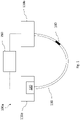
- the optical sensing system 100 comprises an optical fibre 130, a light source 120, a first interrogator 110a and a second interrogator 110b.
- the optical fibre 130 comprises an optical sensor 140.
- the optical sensor is a fibre Bragg grating (FBG) sensor comprising periodic variations in the refractive index of the core of the optical fibre 130 along a section of the length of the optical fibre 130.
- the optical sensor 140 may be a distributed sensor (for example, operating according to the principles of Rayleigh, Brillouin or Raman scattering), a long-period grating sensor, or a tilted grating sensor.
- the wavelength of a band of light reflected from the optical sensor 140 is dependent on the strain of the optical fibre 130 within which the optical sensor is located and/or the temperature to which the optical sensor is subjected.
- FBG sensors are advantageous as they are lightweight and the spacing between FBG elements may be below 1 mm.
- the FBG sensor is etched directly into the core of the optical fibre 130.
- the optical fibre 130 may comprise multiple optical sensors.
- the optical fibre 130 may comprise two optical sensors 140. Each of the two optical sensors may be configured to operate at a different frequency range.
- the optical fibre 130 may comprise multiple optical sensors forming a continuous grating. As a result, a large number of sensing points can be located in a small area.
- the optical fibre 130 may comprise a large number of optical sensors, for example, over 1000 FBG sensors.
- the optical fibre 130 may comprise a small number of optical sensors, for example, 10 FBG sensors.
- the optical fibre 130 may be embedded or attached to a structure, such as a safety critical system of an aircraft.
- the optical sensor 140 is sensitive to changes in strain and/or temperature of the structure. The strain and/or temperature of the structure are determined by analysing optical characteristics of the optical sensor 140.
- the optical characteristics of the optical sensor 140 change.
- the optical sensor 140 is an FBG sensor
- the spacing of the grating of the FBG sensor changes. Therefore, the emission wavelength of the FBG sensor changes. For example, if a compression is applied to the FBG sensor, the spacing of the grating is reduced, engendering a blue shift in wavelength. In contrast, if a tension is applied to the FBG sensor, the spacing of the grating is increased, engendering a red shift in wavelength.
- the optical characteristics of the optical sensor 140 may also change. In particular, changes in temperature may cause the refractive indices of the optical sensor to change. In some cases, changes in the temperature of the optical fibre 130 may additionally or alternatively cause the optical sensor to thermally expand or contract.
- the light source 120 is placed at a first end of the optical fibre 130, and is configured to direct light towards the optical sensor 140.
- the first interrogator 110a may comprise the light source 120.
- the light source 120 may be a tuneable laser.
- the light source 120 may be a broadband light source or a broadband light source with tuneable a narrowband filter.
- the first interrogator 110a is placed at the first end of the optical fibre 130, and the second interrogator 110b is placed at a second, opposite end of the optical fibre 130.
- the first interrogator 110a is configured to receive reflected light from the optical sensor 140
- the second interrogator 110b is configured to receive transmitted light from the optical sensor 140.
- Each interrogator 110a, 110b is configured to determine strain and/or temperature at the optical sensor 140 based on the received light.
- the first interrogator 110a is configured to determine strain and/or temperature at the optical sensor 140 based on the received reflected light
- the second interrogator 110b is configured to determine strain and/or temperature at the optical sensor 140 based on the received transmitted light.
- the optical characteristics of the optical sensor 140 may be represented as optical spectra.
- the optical characteristics may represent a pattern or spacing of the grating of the FBG sensor.
- the optical sensor receives light from the light source 120 emitting a full wavelength optical spectrum. The light passes through the optical fibre 130 and reaches the optical sensor 140. A characteristic of the light is modified by the optical sensor and an optical spectrum is obtained. The characteristic of the light may be, for example, a spectrum of wavelengths.
- the strain and/or temperature determined by the interrogators 110a, 110b may be used to determine the behaviour or properties of the structure to which the optical fibre 130 is attached. For example, the strain may be used to determine load or torque of safety critical applications of the structure.
- each interrogator 110a, 110b comprises at least one light measurer, and is configured to determine a strain and/or temperature of the structure, to which the optical fibre 130 is attached, based on the optical light received at the light measurer from the optical sensor 140.
- the light measurer may be, for example, a wavelength meter, a photodetector, or a photodiode, such as an avalanche photodiode or a PIN diode.
- the interrogator 110a may comprise a primary optical splitter, a plurality of secondary optical splitters, the light source 120, a processor, a plurality of light measurers, and an analogue to digital converter.
- the processor is communicatively connected to the light measurers.
- the light source 120 may be arranged to output light into the primary optical splitter.
- the primary optical splitter splits the light received from the light source 120 into two portions, and these two portions are fed into the first and second secondary optical splitters, respectively.
- the portion of light received from the primary optical splitter is sent through optical sensor 140.
- the reflected light from optical sensor 140 passes back through the first secondary optical splitter to the first light measurer, and the reflected light from the optical sensor 140 passes back through the second secondary optical splitter to the second light measurer.
- the, or each of the, light measurer(s) may be a wavelength meter configured to measure the wavelength of the light reflected from the optical sensor 140.
- the processor processes the wavelength(s) measured by light measurers, and converts the measured wavelengths (for example via a calibration) into a mechanical force or thermal energy applied to the sensors.
- the, or each of the, light measurer(s) may be a photodetector or a photodiode such as an avalanche photodiode or a PIN diode configured to measure the intensity of light reflected from the optical sensor 140.
- the analogue to digital converter is arranged to convert the analogue photodiode signals into digital signals, which are then provided to the processor.
- the processor is arranged to control the tuneable laser to emit light successively at different wavelengths, and at the same time monitor light intensity signals received from the photodiodes.
- the processor can thus determine for which emitted wavelength the highest intensity of reflected light is detected, and thereby determine the wavelength of light most reflected by the optical sensor at that point in time.
- the processor may then convert the determined wavelengths (for example via a calibration) into a mechanical force or thermal energy applied to the sensors.
- the first and second interrogators 110a, 110b may be identical interrogators, each being configured to operate in a different operational mode.
- the first interrogator 110a is configured to operate in a mode in which the reflected light is detected and analysed
- the second interrogator 110b is configured to operate in a mode in which the transmitted light is detected and analysed.
- the second interrogator 110b may comprise a further light source which is turned off.
- the light source of the first interrogator 110a and the further light source of the second interrogator 110b may be operate alternately. In this configuration, one of the interrogators continues to detect reflected light, and the other of the interrogators detects transmitted light.
- Each of the interrogators 110a, 100b then alternates between reflected light and transmitted light according to which of the light sources in turned on.
- the light source 120 and the further light source may be identical. Additionally or alternatively, the further light source may be used to replace the light source 140 in the event of a failure of the light source 120. That way, if the optical sensing system 100 is part of a safety critical application of an aircraft, it is possible to avoid common mode failure as, in case of a failure of one of the light sources, the other light source can be used as a backup light source.
- the other one of the first interrogator 110a or the second interrogator 110b can continue to measure strain and/or temperature of the optical fibre 130, therefore preventing common mode failure of safety critical applications.
- having one of the two interrogators 110a, 110b analysing the reflected light and the other interrogator detecting the transmitted light prevents common mode failure.
- having the first and second interrogators 100a, 110b operating in two different modes provides a simple way to obtain two different measurements.
- the optical sensing system 100 may comprise a comparing unit 150 configured to compare the strain or temperature results determined by the first and second interrogators 110a, 110b.
- the first and second interrogators 110a, 110b may be connected to a comparing unit 150, which may be, for example a computer, which receives the results of analysis of each of the first and second interrogators 110a, 110b.
- the comparing unit may be restarted. Additionally or alternatively, the first and second interrogators 110a, 110b may be restarted.
- the system 100 may record or indicate a fault or failure.
- each of the first and second interrogators 110a, 110b may be connected to a further comparing unit, which again compares the results of analysis of each of the first and second interrogators 110a, 100b.
- the provision of a pair of comparing units provides a level of redundancy, should one of the comparing units fail.
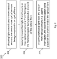
- FIG. 2 there is shown a flow diagram of a method 200 for sensing strain or temperature according to an example.
- the method may be implemented by the optical sensing system 100 described above.
- the method 200 comprises, at a first block 202, directing light towards one or more optical sensors 140, the one or more optical sensors 140 being comprised in an optical fibre 130.
- Each of the optical sensors may be an FBG sensor. Additionally or alternatively, different optical sensors may have different optical characteristics. For example, different optical sensors may operate at a different frequency ranges (i.e. have different frequency responses).
- the optical fibre 130 may be embedded in or attached to a safety critical system, such as a landing gear, braking system, an engine control system, in order to sense the strain applied on the optical fibre 130 by the safety critical system or the temperature of the safety critical system.
- Light may be directed from a light source 120 towards the optical sensors 140.
- light may be directed from two light sources towards the optical sensors 140, each light source operating alternately for a predetermined time.
- a light source may be placed at one end of the optical fibre 130 and a further light source at an opposite end of the optical fibre 130.
- the light may be directed towards the optical sensors 140 using the light source placed at the one end of the optical fibre 130, and directing light towards the one optical sensors using the further light source in the event of a failure of the light source. Therefore, one of the two light sources may be used as a backup light source.
- the method 200 also comprises, at a second block 204, receiving transmitted light from the optical sensors 140 at a first interrogator 110a, the first interrogator 110a being placed at one end of the optical fibre 130 and, at a third block 206, receiving reflected light from the optical sensors 140 at a second interrogator 110b, the second interrogator 110b being placed at the another end of the optical fibre 130.
- first and second interrogators 110a, 110b may be identical but each operating in a different mode.
- the first interrogator 110a may be operating in a mode which enables the analysis of received transmitted light
- the second interrogator 110b may be operating in a mode which enables the analysis of received reflected light.
- the first and second interrogators 110a, 110b receive transmitted and reflected light, respectively, received from the optical sensors 140.
- Each interrogator 110a, 110b analyses the received light from the optical sensors and determines strain and/or temperature applied to the optical fibre 130 based on the received light.
- the first and second interrogators 110a, 110b may analyse a spectrum of wavelength representing the characteristics of the optical sensors 140.
- the method 200 may comprise a further step of receiving, at a comparing unit, the strain or temperature results determined by each of the first and second interrogators 110a, 110b and comparing the two results. In the event of a discrepancy between the two results, the method 200 may comprise a further step of switching off or restarting one or both of the first and second interrogators 110a, 110b and/or the comparing unit.
- Figure 3 is a view of an aircraft 1000 including an optical sensing system 100 according to an example.
- the aircraft 1000 may comprise any of the optical systems 100 described above.
- the aircraft 1000 may comprise one or more optical sensing systems 100, each optical sensing system 100 having an optical fibre 130 attached to a safety critical application.
- the optical fibre 130 may be attached to the braking system, landing gear control system, engine control system, or a fuel system of the aircraft 1000.
- Each of the optical sensing systems 100 may be used to sense strain or temperature of a safety critical system of the aircraft 1000.
- one optical sensing system 100 may be used to sense the strain applied by the wing load alleviation system of the aircraft 1000.
- the optical sensing system 100 described herein provides an arrangement in which a failure condition occurs only in the event of at least two failures in the system.
- the optical sensing system 100 described herein prevents common mode failure of safety critical systems.
- other advantages include limiting the need for hardware development while ensuring safety.
- two identical interrogators may be used, each operating in a different mode.
- two identical light sources may be used, one being used to replace the other in case of failure, or each light source being used alternately.
- One of the interrogators receives reflected light, and the other of the interrogators receives transmitted light.
- each of the interrogators may alternate between receiving reflected light and receiving transmitted light.
- the optical fibre 130 may comprise optical sensors 140 that operate at different frequencies. Should one of the optical sensors fail, another of the optical sensors may then continue to function. Therefore, the present application provides a simple way to obtain the redundancy necessary for safety critical applications.
Landscapes
- Physics & Mathematics (AREA)
- General Physics & Mathematics (AREA)
- Optics & Photonics (AREA)
- Chemical & Material Sciences (AREA)
- Analytical Chemistry (AREA)
- Measuring Temperature Or Quantity Of Heat (AREA)
- Length Measuring Devices By Optical Means (AREA)
- Optical Transform (AREA)
- Engineering & Computer Science (AREA)
- Microelectronics & Electronic Packaging (AREA)
Abstract
Description
- The present invention relates to an optical sensing system for sensing strain or temperature, and to vehicles, such as aircraft, comprising the same.
- An aircraft may comprise fibre Bragg sensors for sensing strain in order to determine load and torque of safety critical applications.
- A first aspect of the present invention provides an optical sensing system comprising: an optical fibre comprising one or more optical sensors; a light source placed at a first end of the optical fibre, wherein the light source is configured to direct light towards the one or more optical sensors; a first interrogator placed at the first end of the optical fibre; and a second interrogator placed at a second, opposite end of the optical fibre, wherein the first interrogator is configured to receive reflected light from the one or more optical sensors, and the second interrogator is configured to receive transmitted light from the one or more optical sensors.
- Optionally, the one or more optical sensors are configured to sense changes in strain or temperature along the optical fibre.
- Optionally, the first and second interrogators are configured to analyse the light received from the one or more optical sensors to determine changes in strain or temperature along the optical fibre.
- Optionally, the optical sensing system comprises a comparing unit configured to compare the strains or temperatures determined by the first and second interrogators.
- Optionally, the optical sensing system comprises a further light source placed at the second end of the optical fibre and configured to direct light towards the one or more optical sensors, optionally in the event of a failure of the light source.
- Optionally, the one or more optical sensors are fibre Bragg grating sensors.
- Optionally, the optical fibre comprises at least two optical sensors configured to operate at two different frequency ranges.
- Optionally, the first and second interrogators are identical interrogators, each being configured to operate in a different operational mode.
- Optionally, the optical fibre is embedded or attached to a safety critical system of an aircraft.
- A second aspect of the present invention provides a method for sensing a strain or temperature, the method comprising: directing light towards one or more optical sensors, the one or more optical sensors being comprised in an optical fibre; receiving transmitted light from the one or more optical sensors at a first interrogator, the first interrogator being placed at one end of the optical fibre; and receiving reflected light from the one or more optical sensors at a second interrogator, the second interrogator being placed at the another end of the optical fibre.
- Optionally, the one or more optical sensors are configured to sense changes in strain or temperature along the optical fibre.
- Optionally, the method comprises analysing the light received from the one or more optical sensors by each of the first and second interrogators and determining changes in strain or temperature along the optical fibre.
- Optionally, the method comprises comparing the strains or temperatures determined by each of the first and second interrogators.
- Optionally, the method comprises providing a light source at one end of the optical fibre and a further light source at an opposite end of the optical fibre, directing light towards one or more optical sensors using the light source, and directing light towards one or more optical sensors using the further light source in the event of a failure of the light source.
- Optionally, the method comprises providing a light source at one end of the optical fibre and a further light source at an opposite end of the optical fibre, directing light towards one or more optical sensors using the light source, and directing light towards one or more optical sensors using the light source or the further light source.
- Optionally, the one or more optical sensors are fibre Bragg grating sensor.
- Optionally, the optical fibre comprises at least two optical sensors configured to operate at two different frequency ranges.
- Optionally, the first and second interrogators are identical interrogators, each being configured to operate in a different operational mode.
- Optionally, the optical fibre is embedded or attached to a safety critical system of an aircraft.
- A third aspect of the present invention provides an aircraft comprising the system of the first aspect.
- Optionally, the system senses changes in strain or temperature of a component of the aircraft.
- Embodiments of the invention will now be described, by way of example only, with reference to the accompanying drawings, in which:
-
Figure 1 shows a schematic view of an optical sensing system according to an example; -
Figure 2 is a flow diagram of a method for sensing strain or temperature according to an example; and -
Figure 3 is a view of an aircraft including an optical sensing system according to an example. - Referring to
Figure 1 , there is shown a schematic view of anoptical sensing system 100, according to an example. Theoptical sensing system 100 comprises anoptical fibre 130, alight source 120, afirst interrogator 110a and asecond interrogator 110b. - The
optical fibre 130 comprises anoptical sensor 140. In this example, the optical sensor is a fibre Bragg grating (FBG) sensor comprising periodic variations in the refractive index of the core of theoptical fibre 130 along a section of the length of theoptical fibre 130. In other examples, theoptical sensor 140 may be a distributed sensor (for example, operating according to the principles of Rayleigh, Brillouin or Raman scattering), a long-period grating sensor, or a tilted grating sensor. - The wavelength of a band of light reflected from the
optical sensor 140 is dependent on the strain of theoptical fibre 130 within which the optical sensor is located and/or the temperature to which the optical sensor is subjected. FBG sensors are advantageous as they are lightweight and the spacing between FBG elements may be below 1 mm. The FBG sensor is etched directly into the core of theoptical fibre 130. Depending on the application, theoptical fibre 130 may comprise multiple optical sensors. For example, theoptical fibre 130 may comprise twooptical sensors 140. Each of the two optical sensors may be configured to operate at a different frequency range. Alternatively, theoptical fibre 130 may comprise multiple optical sensors forming a continuous grating. As a result, a large number of sensing points can be located in a small area. Theoptical fibre 130 may comprise a large number of optical sensors, for example, over 1000 FBG sensors. Alternatively, theoptical fibre 130 may comprise a small number of optical sensors, for example, 10 FBG sensors. - The
optical fibre 130 may be embedded or attached to a structure, such as a safety critical system of an aircraft. Theoptical sensor 140 is sensitive to changes in strain and/or temperature of the structure. The strain and/or temperature of the structure are determined by analysing optical characteristics of theoptical sensor 140. - When a mechanical force is applied to the
optical fibre 130, the optical characteristics of theoptical sensor 140 change. In particular, if theoptical sensor 140 is an FBG sensor, when the mechanical force is applied, the spacing of the grating of the FBG sensor changes. Therefore, the emission wavelength of the FBG sensor changes. For example, if a compression is applied to the FBG sensor, the spacing of the grating is reduced, engendering a blue shift in wavelength. In contrast, if a tension is applied to the FBG sensor, the spacing of the grating is increased, engendering a red shift in wavelength. When the temperature of theoptical fibre 130 changes, the optical characteristics of theoptical sensor 140 may also change. In particular, changes in temperature may cause the refractive indices of the optical sensor to change. In some cases, changes in the temperature of theoptical fibre 130 may additionally or alternatively cause the optical sensor to thermally expand or contract. - The
light source 120 is placed at a first end of theoptical fibre 130, and is configured to direct light towards theoptical sensor 140. For example, thefirst interrogator 110a may comprise thelight source 120. Thelight source 120 may be a tuneable laser. In another example, thelight source 120 may be a broadband light source or a broadband light source with tuneable a narrowband filter. - The
first interrogator 110a is placed at the first end of theoptical fibre 130, and thesecond interrogator 110b is placed at a second, opposite end of theoptical fibre 130. Thefirst interrogator 110a is configured to receive reflected light from theoptical sensor 140, and thesecond interrogator 110b is configured to receive transmitted light from theoptical sensor 140. Eachinterrogator optical sensor 140 based on the received light. In particular, thefirst interrogator 110a is configured to determine strain and/or temperature at theoptical sensor 140 based on the received reflected light, and thesecond interrogator 110b is configured to determine strain and/or temperature at theoptical sensor 140 based on the received transmitted light. The optical characteristics of theoptical sensor 140 may be represented as optical spectra. For example, if theoptical sensor 140 is an FBG sensor, the optical characteristics may represent a pattern or spacing of the grating of the FBG sensor. In use, the optical sensor receives light from thelight source 120 emitting a full wavelength optical spectrum. The light passes through theoptical fibre 130 and reaches theoptical sensor 140. A characteristic of the light is modified by the optical sensor and an optical spectrum is obtained. The characteristic of the light may be, for example, a spectrum of wavelengths. The strain and/or temperature determined by theinterrogators optical fibre 130 is attached. For example, the strain may be used to determine load or torque of safety critical applications of the structure. - Broadly speaking, each
interrogator optical fibre 130 is attached, based on the optical light received at the light measurer from theoptical sensor 140. The light measurer may be, for example, a wavelength meter, a photodetector, or a photodiode, such as an avalanche photodiode or a PIN diode. - The
interrogator 110a may comprise a primary optical splitter, a plurality of secondary optical splitters, thelight source 120, a processor, a plurality of light measurers, and an analogue to digital converter. The processor is communicatively connected to the light measurers. - The
light source 120 may be arranged to output light into the primary optical splitter. The primary optical splitter splits the light received from thelight source 120 into two portions, and these two portions are fed into the first and second secondary optical splitters, respectively. From the first secondary optical splitter, the portion of light received from the primary optical splitter is sent throughoptical sensor 140. The reflected light fromoptical sensor 140 passes back through the first secondary optical splitter to the first light measurer, and the reflected light from theoptical sensor 140 passes back through the second secondary optical splitter to the second light measurer. - In embodiments in which the light source is a broadband light source, the, or each of the, light measurer(s) may be a wavelength meter configured to measure the wavelength of the light reflected from the
optical sensor 140. The processor processes the wavelength(s) measured by light measurers, and converts the measured wavelengths (for example via a calibration) into a mechanical force or thermal energy applied to the sensors. - In embodiments in which the
light source 120 is a tuneable narrow band optical source, such as a tuneable laser as in the present embodiment, the, or each of the, light measurer(s) may be a photodetector or a photodiode such as an avalanche photodiode or a PIN diode configured to measure the intensity of light reflected from theoptical sensor 140. The analogue to digital converter is arranged to convert the analogue photodiode signals into digital signals, which are then provided to the processor. In this example, the processor is arranged to control the tuneable laser to emit light successively at different wavelengths, and at the same time monitor light intensity signals received from the photodiodes. The processor can thus determine for which emitted wavelength the highest intensity of reflected light is detected, and thereby determine the wavelength of light most reflected by the optical sensor at that point in time. The processor may then convert the determined wavelengths (for example via a calibration) into a mechanical force or thermal energy applied to the sensors. - It will be appreciated that although two secondary optical splitters and two associated light measurers are described in the examples above, in other examples there may be any number of optical splitters and associated light measurers. For example, depending on the number of optical sensors required, there may be one pair of secondary optical splitters and an associated light measurer for each optical sensor. In some examples, as noted above, there may be only one light measurer and associated secondary optical splitter for all optical sensors.
- The first and
second interrogators first interrogator 110a is configured to operate in a mode in which the reflected light is detected and analysed, and, in contrast, thesecond interrogator 110b is configured to operate in a mode in which the transmitted light is detected and analysed. Thesecond interrogator 110b may comprise a further light source which is turned off. Alternatively, the light source of thefirst interrogator 110a and the further light source of thesecond interrogator 110b may be operate alternately. In this configuration, one of the interrogators continues to detect reflected light, and the other of the interrogators detects transmitted light. Each of theinterrogators 110a, 100b then alternates between reflected light and transmitted light according to which of the light sources in turned on. Thelight source 120 and the further light source may be identical. Additionally or alternatively, the further light source may be used to replace thelight source 140 in the event of a failure of thelight source 120. That way, if theoptical sensing system 100 is part of a safety critical application of an aircraft, it is possible to avoid common mode failure as, in case of a failure of one of the light sources, the other light source can be used as a backup light source. - Similarly, in the event of a failure of one of the
first interrogator 110a or thesecond interrogator 110b, the other one of thefirst interrogator 110a or thesecond interrogator 110b can continue to measure strain and/or temperature of theoptical fibre 130, therefore preventing common mode failure of safety critical applications. Additionally, as indicated above, having one of the twointerrogators second interrogators - The
optical sensing system 100 may comprise a comparingunit 150 configured to compare the strain or temperature results determined by the first andsecond interrogators second interrogators unit 150, which may be, for example a computer, which receives the results of analysis of each of the first andsecond interrogators second interrogators second interrogators system 100 may record or indicate a fault or failure. In another example, each of the first andsecond interrogators second interrogators 110a, 100b. The provision of a pair of comparing units provides a level of redundancy, should one of the comparing units fail. - Referring to
Figure 2 , there is shown a flow diagram of amethod 200 for sensing strain or temperature according to an example. The method may be implemented by theoptical sensing system 100 described above. - The
method 200 comprises, at afirst block 202, directing light towards one or moreoptical sensors 140, the one or moreoptical sensors 140 being comprised in anoptical fibre 130. Each of the optical sensors may be an FBG sensor. Additionally or alternatively, different optical sensors may have different optical characteristics. For example, different optical sensors may operate at a different frequency ranges (i.e. have different frequency responses). Theoptical fibre 130 may be embedded in or attached to a safety critical system, such as a landing gear, braking system, an engine control system, in order to sense the strain applied on theoptical fibre 130 by the safety critical system or the temperature of the safety critical system. - Light may be directed from a
light source 120 towards theoptical sensors 140. Alternatively, if the method is implemented in a safety critical application, light may be directed from two light sources towards theoptical sensors 140, each light source operating alternately for a predetermined time. For example, a light source may be placed at one end of theoptical fibre 130 and a further light source at an opposite end of theoptical fibre 130. In another example, the light may be directed towards theoptical sensors 140 using the light source placed at the one end of theoptical fibre 130, and directing light towards the one optical sensors using the further light source in the event of a failure of the light source. Therefore, one of the two light sources may be used as a backup light source. - The
method 200 also comprises, at asecond block 204, receiving transmitted light from theoptical sensors 140 at afirst interrogator 110a, thefirst interrogator 110a being placed at one end of theoptical fibre 130 and, at athird block 206, receiving reflected light from theoptical sensors 140 at asecond interrogator 110b, thesecond interrogator 110b being placed at the another end of theoptical fibre 130. - For example, the first and
second interrogators first interrogator 110a may be operating in a mode which enables the analysis of received transmitted light, thesecond interrogator 110b may be operating in a mode which enables the analysis of received reflected light. - In an example, the first and
second interrogators optical sensors 140. Eachinterrogator optical fibre 130 based on the received light. For example, the first andsecond interrogators optical sensors 140. - The
method 200 may comprise a further step of receiving, at a comparing unit, the strain or temperature results determined by each of the first andsecond interrogators method 200 may comprise a further step of switching off or restarting one or both of the first andsecond interrogators -
Figure 3 is a view of anaircraft 1000 including anoptical sensing system 100 according to an example. Theaircraft 1000 may comprise any of theoptical systems 100 described above. - The
aircraft 1000 may comprise one or moreoptical sensing systems 100, eachoptical sensing system 100 having anoptical fibre 130 attached to a safety critical application. For example, theoptical fibre 130 may be attached to the braking system, landing gear control system, engine control system, or a fuel system of theaircraft 1000. Each of theoptical sensing systems 100 may be used to sense strain or temperature of a safety critical system of theaircraft 1000. For example, oneoptical sensing system 100 may be used to sense the strain applied by the wing load alleviation system of theaircraft 1000. - The
optical sensing system 100 described herein provides an arrangement in which a failure condition occurs only in the event of at least two failures in the system. In particular, theoptical sensing system 100 described herein prevents common mode failure of safety critical systems. Additionally, other advantages include limiting the need for hardware development while ensuring safety. For example, as explained above, two identical interrogators may be used, each operating in a different mode. Similarly, two identical light sources may be used, one being used to replace the other in case of failure, or each light source being used alternately. One of the interrogators receives reflected light, and the other of the interrogators receives transmitted light. Moreover, each of the interrogators may alternate between receiving reflected light and receiving transmitted light. Accordingly, in the event that the optical fibre is damaged or cut, reflected light may continue to be received at one of the interrogators. Furthermore, theoptical fibre 130 may compriseoptical sensors 140 that operate at different frequencies. Should one of the optical sensors fail, another of the optical sensors may then continue to function. Therefore, the present application provides a simple way to obtain the redundancy necessary for safety critical applications. - While some embodiments of the present invention have been described in the context of use within an aircraft, it should be appreciated that the invention has utility in other applications, including in vehicles other than aircraft, such as spacecraft, automobiles, railway vehicles, and watercraft.
- The above embodiments are to be understood as illustrative examples of the invention. It is to be understood that any feature described in relation to any one embodiment may be used alone, or in combination with other features described, and may also be used in combination with one or more features of any other of the embodiments, or any combination of any other of the embodiments. Furthermore, equivalents and modifications not described above may also be employed without departing from the scope of the invention, which is defined in the accompanying claims.
- It is to be noted that the term "or" as used herein is to be interpreted to mean "and/or", unless expressly stated otherwise
Claims (15)
- An optical sensing system comprising:an optical fibre comprising one or more optical sensors;a light source placed at a first end of the optical fibre, wherein the light source is configured to direct light towards the one or more optical sensors;a first interrogator placed at the first end of the optical fibre; anda second interrogator placed at a second, opposite end of the optical fibre,wherein the first interrogator is configured to receive reflected light from the one or more optical sensors, and the second interrogator is configured to receive transmitted light from the one or more optical sensors.
- An optical sensing system according to claim 1, wherein the one or more optical sensors are configured to sense changes in strain or temperature along the optical fibre, the optical sensors optionally being fibre Bragg grating sensors and the optical fibre optionally comprising at least two optical sensors configured to operate at two different frequency ranges.
- An optical sensing system according to claims 1 or 2, wherein the first and second interrogators are configured to analyse the light received from the one or more optical sensors to determine changes in strain or temperature along the optical fibre.
- An optical sensing system according to claim 3, wherein the optical sensing system comprises a comparing unit configured to compare the strains or temperatures determined by the first and second interrogators.
- An optical sensing system according to any of the preceding claims, wherein the optical sensing system comprises a further light source placed at the second end of the optical fibre and configured to direct light towards the one or more optical sensors, optionally in the event of a failure of the light source.
- An optical sensing system according to any of the preceding claims, wherein the first and second interrogators are identical interrogators, each being configured to operate in a different operational mode.
- An optical sensing system according to any of the preceding claims, wherein the optical fibre is embedded or attached to a safety critical system of an aircraft.
- A method for sensing a strain or temperature, the method comprising:directing light towards one or more optical sensors, the one or more optical sensors being comprised in an optical fibre;receiving transmitted light from the one or more optical sensors at a first interrogator, the first interrogator being placed at one end of the optical fibre; andreceiving reflected light from the one or more optical sensors at a second interrogator, the second interrogator being placed at the another end of the optical fibre.
- A method according to claim 8, wherein the one or more optical sensors are configured to sense changes in strain or temperature along the optical fibre, the optical sensors optionally being fibre Bragg grating sensors and optionally at least two optical sensors are configured to operate at two different frequency ranges.
- A method according to claims 8 or 9, wherein the method comprises analysing the light received from the one or more optical sensors by each of the first and second interrogators and determining changes in strain or temperature along the optical fibre.
- A method according to any of claims 8 to 10, wherein the method comprises comparing the strains or temperatures determined by each of the first and second interrogators.
- A method according to any of claims 8 to 11, wherein the method comprises providing a light source at one end of the optical fibre and a further light source at an opposite end of the optical fibre, directing light towards one or more optical sensors using the light source, anddirecting light towards one or more optical sensors using the light source or the further light source, ordirecting light towards one or more optical sensors using the further light source in the event of a failure of the light source.
- A method according to any claims 8 to 12, wherein the first and second interrogators are identical interrogators, each being configured to operate in a different operational mode.
- A method according to any claims 8 to 13, wherein the optical fibre is embedded or attached to a safety critical system of an aircraft.
- An aircraft comprising the system according to any of claims 1 to 7.
Applications Claiming Priority (1)
| Application Number | Priority Date | Filing Date | Title |
|---|---|---|---|
| GB2109013.9A GB2608145A (en) | 2021-06-23 | 2021-06-23 | Optical sensing system |
Publications (2)
| Publication Number | Publication Date |
|---|---|
| EP4109050A1 true EP4109050A1 (en) | 2022-12-28 |
| EP4109050B1 EP4109050B1 (en) | 2024-12-11 |
Family
ID=77050416
Family Applications (1)
| Application Number | Title | Priority Date | Filing Date |
|---|---|---|---|
| EP22180854.6A Active EP4109050B1 (en) | 2021-06-23 | 2022-06-23 | Optical sensing system |
Country Status (4)
| Country | Link |
|---|---|
| US (1) | US11927496B2 (en) |
| EP (1) | EP4109050B1 (en) |
| CN (1) | CN115507763A (en) |
| GB (1) | GB2608145A (en) |
Cited By (1)
| Publication number | Priority date | Publication date | Assignee | Title |
|---|---|---|---|---|
| EP4560941A1 (en) | 2023-11-27 | 2025-05-28 | Airbus Defence and Space GmbH | Photonic transceiver module, periphery device, communication system and apparatus comprising same |
Families Citing this family (3)
| Publication number | Priority date | Publication date | Assignee | Title |
|---|---|---|---|---|
| US12351295B2 (en) * | 2022-11-21 | 2025-07-08 | Hamilton Sundstrand Corporation | Fiber optic slat flap system and control lever |
| US12560547B2 (en) * | 2023-09-22 | 2026-02-24 | Honeywell International Inc. | Fiber optic profiler for early damage warning |
| WO2026074480A1 (en) * | 2024-10-04 | 2026-04-09 | Brembo N.V. | Method and device for detecting and measuring at least one dynamic mechanical quantity and one thermal quantity, in a system or component subject to external load, such as a braking system, by means of photonic sensors incorporated into the system or component |
Citations (3)
| Publication number | Priority date | Publication date | Assignee | Title |
|---|---|---|---|---|
| WO2013109987A2 (en) * | 2012-01-20 | 2013-07-25 | The Board Of Trustees Of The Leland Stanford Junior University | System and method for measuring perturbations using a slow-light fiber bragg grating sensor |
| EP2643663B1 (en) * | 2010-11-24 | 2015-03-04 | Vestas Wind Systems A/S | Long fibre optic sensor system in a wind turbine component |
| US20160084640A1 (en) * | 2014-09-22 | 2016-03-24 | The Boeing Company | Real-time non-linear optical strain gauge system |
Family Cites Families (13)
| Publication number | Priority date | Publication date | Assignee | Title |
|---|---|---|---|---|
| US5144690A (en) | 1990-12-03 | 1992-09-01 | Corning Incorporated | Optical fiber sensor with localized sensing regions |
| GB9317576D0 (en) | 1993-08-24 | 1993-10-06 | British Aerospace | Fibre optic damage detection system |
| GB0031646D0 (en) * | 2000-12-22 | 2001-02-07 | European Community | Method and apparatus for crack and fracture detection utilizing bragg gratings |
| US6753520B2 (en) * | 2001-09-17 | 2004-06-22 | Centro De Investigacion Cientifica Y De Educacion Superior De Ensenada (Cicese) | Fiber optic sensor with transmission/reflection analyzer |
| US7030974B2 (en) * | 2003-03-03 | 2006-04-18 | Centro de Investigacion Cientifica y de Educacion Superior de Ensenada | Alarm condition distributed fiber optic sensor with storage transmission-reflection analyzer |
| US6917750B2 (en) * | 2003-05-29 | 2005-07-12 | 3M Innovative Properties Company | System and method for characterizing optical devices |
| DE102004007801A1 (en) * | 2004-02-18 | 2005-09-08 | Robert Bosch Gmbh | Motor vehicle impact or crash sensor has one or more optical wave guides built into the vehicle so that in the event of a crash the passage of light in one or more of them is interrupted and a crash is indicated |
| US7011453B1 (en) * | 2004-12-09 | 2006-03-14 | The Boeing Company | Method for determining fiber optic fault location |
| US7539361B2 (en) * | 2006-10-05 | 2009-05-26 | Harris Corporation | Fiber optic device for measuring a parameter of interest |
| US8208767B2 (en) | 2009-11-10 | 2012-06-26 | Baker Hughes Incorporated | Sensor array configuration for extending useful sensing length of a swept-wavelength interferometry based system |
| US8576392B2 (en) | 2011-02-09 | 2013-11-05 | Siemens Energy, Inc. | Multiplexed optical fiber crack sensor |
| GB201601060D0 (en) * | 2016-01-20 | 2016-03-02 | Fotech Solutions Ltd | Distributed optical fibre sensors |
| US10768055B2 (en) * | 2018-03-06 | 2020-09-08 | Kidde Technologies, Inc. | Device and method of calibrating fiber Bragg grating based fiber optic overheat systems |
-
2021
- 2021-06-23 GB GB2109013.9A patent/GB2608145A/en active Pending
-
2022
- 2022-06-21 CN CN202210702383.1A patent/CN115507763A/en active Pending
- 2022-06-22 US US17/846,812 patent/US11927496B2/en active Active
- 2022-06-23 EP EP22180854.6A patent/EP4109050B1/en active Active
Patent Citations (3)
| Publication number | Priority date | Publication date | Assignee | Title |
|---|---|---|---|---|
| EP2643663B1 (en) * | 2010-11-24 | 2015-03-04 | Vestas Wind Systems A/S | Long fibre optic sensor system in a wind turbine component |
| WO2013109987A2 (en) * | 2012-01-20 | 2013-07-25 | The Board Of Trustees Of The Leland Stanford Junior University | System and method for measuring perturbations using a slow-light fiber bragg grating sensor |
| US20160084640A1 (en) * | 2014-09-22 | 2016-03-24 | The Boeing Company | Real-time non-linear optical strain gauge system |
Cited By (1)
| Publication number | Priority date | Publication date | Assignee | Title |
|---|---|---|---|---|
| EP4560941A1 (en) | 2023-11-27 | 2025-05-28 | Airbus Defence and Space GmbH | Photonic transceiver module, periphery device, communication system and apparatus comprising same |
Also Published As
| Publication number | Publication date |
|---|---|
| US20220412827A1 (en) | 2022-12-29 |
| US11927496B2 (en) | 2024-03-12 |
| GB2608145A (en) | 2022-12-28 |
| EP4109050B1 (en) | 2024-12-11 |
| GB202109013D0 (en) | 2021-08-04 |
| CN115507763A (en) | 2022-12-23 |
Similar Documents
| Publication | Publication Date | Title |
|---|---|---|
| EP4109050B1 (en) | Optical sensing system | |
| US10260964B2 (en) | Optical fiber sensor system for detecting temperature changes in an aircraft | |
| US6335524B1 (en) | High speed demodulation systems for fiber optic grating sensors | |
| US5591965A (en) | Multiparameter sensor system using a multiple grating fiber optic birefringent fiber | |
| KR101209627B1 (en) | Optical fiber sensor system using an optical spectrometer | |
| US7119325B2 (en) | System and method for monitoring environmental effects using optical sensors | |
| EP4127621B1 (en) | Sensor assembly | |
| CN107884477B (en) | Acoustic emission detection system and detection method based on fiber bragg grating sensor | |
| US20090092352A1 (en) | Optical fiber strain sensor | |
| US6563969B2 (en) | Multiplexed fiber laser sensor system | |
| US6981406B2 (en) | Fiber optic cylinder pressure measurement system for a combustion engine | |
| EP3967996B1 (en) | Fiber optic load sensors and systems therefor | |
| US6961120B2 (en) | Strain measurement module with tunable light generator and strain measurement system using the same | |
| Sagadeev et al. | Measurement of deformation of aircraft structures made of composite materials with fiber-optic sensors | |
| Shlyagin et al. | Twin grating-based interferometric fiber sensor | |
| JP7728330B2 (en) | Physical quantity measuring device | |
| JP2025515086A (en) | Measurement method for detecting mechanical force acting on an object, and measurement device equipped with optical fiber sensor unit | |
| JP2004347575A (en) | FBG sensing device | |
| RU2685439C1 (en) | Onboard distributed control and leaks diagnostics system based on technologies of photonics | |
| RU2783171C1 (en) | Method and apparatus for polling sensor elements of fibre bragg gratings through the end of the fibre using an annular speckle pattern | |
| JP3761025B2 (en) | Optical spectrum analyzer | |
| CN120907453A (en) | Method and device for online monitoring of strain of pressure relief valve film of extra-high voltage transformer | |
| KR20180100757A (en) | System and method for long-distance monitoring using optical sensor | |
| Smith et al. | Design of a fiber Bragg based measurement system for strain and temperature monitoring | |
| JPH11183290A (en) | Optical fiber measurement system |
Legal Events
| Date | Code | Title | Description |
|---|---|---|---|
| PUAI | Public reference made under article 153(3) epc to a published international application that has entered the european phase |
Free format text: ORIGINAL CODE: 0009012 |
|
| STAA | Information on the status of an ep patent application or granted ep patent |
Free format text: STATUS: THE APPLICATION HAS BEEN PUBLISHED |
|
| AK | Designated contracting states |
Kind code of ref document: A1 Designated state(s): AL AT BE BG CH CY CZ DE DK EE ES FI FR GB GR HR HU IE IS IT LI LT LU LV MC MK MT NL NO PL PT RO RS SE SI SK SM TR |
|
| STAA | Information on the status of an ep patent application or granted ep patent |
Free format text: STATUS: REQUEST FOR EXAMINATION WAS MADE |
|
| 17P | Request for examination filed |
Effective date: 20230628 |
|
| RBV | Designated contracting states (corrected) |
Designated state(s): AL AT BE BG CH CY CZ DE DK EE ES FI FR GB GR HR HU IE IS IT LI LT LU LV MC MK MT NL NO PL PT RO RS SE SI SK SM TR |
|
| GRAP | Despatch of communication of intention to grant a patent |
Free format text: ORIGINAL CODE: EPIDOSNIGR1 |
|
| STAA | Information on the status of an ep patent application or granted ep patent |
Free format text: STATUS: GRANT OF PATENT IS INTENDED |
|
| RIC1 | Information provided on ipc code assigned before grant |
Ipc: G01D 5/353 20060101AFI20240612BHEP |
|
| INTG | Intention to grant announced |
Effective date: 20240702 |
|
| RIN1 | Information on inventor provided before grant (corrected) |
Inventor name: GADD, MATTHEW |
|
| GRAS | Grant fee paid |
Free format text: ORIGINAL CODE: EPIDOSNIGR3 |
|
| GRAA | (expected) grant |
Free format text: ORIGINAL CODE: 0009210 |
|
| STAA | Information on the status of an ep patent application or granted ep patent |
Free format text: STATUS: THE PATENT HAS BEEN GRANTED |
|
| AK | Designated contracting states |
Kind code of ref document: B1 Designated state(s): AL AT BE BG CH CY CZ DE DK EE ES FI FR GB GR HR HU IE IS IT LI LT LU LV MC MK MT NL NO PL PT RO RS SE SI SK SM TR |
|
| REG | Reference to a national code |
Ref country code: GB Ref legal event code: FG4D |
|
| REG | Reference to a national code |
Ref country code: CH Ref legal event code: EP |
|
| REG | Reference to a national code |
Ref country code: IE Ref legal event code: FG4D |
|
| REG | Reference to a national code |
Ref country code: DE Ref legal event code: R096 Ref document number: 602022008546 Country of ref document: DE |
|
| REG | Reference to a national code |
Ref country code: LT Ref legal event code: MG9D |
|
| PG25 | Lapsed in a contracting state [announced via postgrant information from national office to epo] |
Ref country code: HR Free format text: LAPSE BECAUSE OF FAILURE TO SUBMIT A TRANSLATION OF THE DESCRIPTION OR TO PAY THE FEE WITHIN THE PRESCRIBED TIME-LIMIT Effective date: 20241211 |
|
| PG25 | Lapsed in a contracting state [announced via postgrant information from national office to epo] |
Ref country code: FI Free format text: LAPSE BECAUSE OF FAILURE TO SUBMIT A TRANSLATION OF THE DESCRIPTION OR TO PAY THE FEE WITHIN THE PRESCRIBED TIME-LIMIT Effective date: 20241211 |
|
| PG25 | Lapsed in a contracting state [announced via postgrant information from national office to epo] |
Ref country code: BG Free format text: LAPSE BECAUSE OF FAILURE TO SUBMIT A TRANSLATION OF THE DESCRIPTION OR TO PAY THE FEE WITHIN THE PRESCRIBED TIME-LIMIT Effective date: 20241211 |
|
| REG | Reference to a national code |
Ref country code: NL Ref legal event code: MP Effective date: 20241211 |
|
| PG25 | Lapsed in a contracting state [announced via postgrant information from national office to epo] |
Ref country code: ES Free format text: LAPSE BECAUSE OF FAILURE TO SUBMIT A TRANSLATION OF THE DESCRIPTION OR TO PAY THE FEE WITHIN THE PRESCRIBED TIME-LIMIT Effective date: 20241211 |
|
| PG25 | Lapsed in a contracting state [announced via postgrant information from national office to epo] |
Ref country code: NO Free format text: LAPSE BECAUSE OF FAILURE TO SUBMIT A TRANSLATION OF THE DESCRIPTION OR TO PAY THE FEE WITHIN THE PRESCRIBED TIME-LIMIT Effective date: 20250311 |
|
| PG25 | Lapsed in a contracting state [announced via postgrant information from national office to epo] |
Ref country code: LV Free format text: LAPSE BECAUSE OF FAILURE TO SUBMIT A TRANSLATION OF THE DESCRIPTION OR TO PAY THE FEE WITHIN THE PRESCRIBED TIME-LIMIT Effective date: 20241211 Ref country code: GR Free format text: LAPSE BECAUSE OF FAILURE TO SUBMIT A TRANSLATION OF THE DESCRIPTION OR TO PAY THE FEE WITHIN THE PRESCRIBED TIME-LIMIT Effective date: 20250312 |
|
| PG25 | Lapsed in a contracting state [announced via postgrant information from national office to epo] |
Ref country code: RS Free format text: LAPSE BECAUSE OF FAILURE TO SUBMIT A TRANSLATION OF THE DESCRIPTION OR TO PAY THE FEE WITHIN THE PRESCRIBED TIME-LIMIT Effective date: 20250311 |
|
| PG25 | Lapsed in a contracting state [announced via postgrant information from national office to epo] |
Ref country code: NL Free format text: LAPSE BECAUSE OF FAILURE TO SUBMIT A TRANSLATION OF THE DESCRIPTION OR TO PAY THE FEE WITHIN THE PRESCRIBED TIME-LIMIT Effective date: 20241211 |
|
| REG | Reference to a national code |
Ref country code: AT Ref legal event code: MK05 Ref document number: 1750699 Country of ref document: AT Kind code of ref document: T Effective date: 20241211 |
|
| PG25 | Lapsed in a contracting state [announced via postgrant information from national office to epo] |
Ref country code: SM Free format text: LAPSE BECAUSE OF FAILURE TO SUBMIT A TRANSLATION OF THE DESCRIPTION OR TO PAY THE FEE WITHIN THE PRESCRIBED TIME-LIMIT Effective date: 20241211 |
|
| PG25 | Lapsed in a contracting state [announced via postgrant information from national office to epo] |
Ref country code: PL Free format text: LAPSE BECAUSE OF FAILURE TO SUBMIT A TRANSLATION OF THE DESCRIPTION OR TO PAY THE FEE WITHIN THE PRESCRIBED TIME-LIMIT Effective date: 20241211 |
|
| PGFP | Annual fee paid to national office [announced via postgrant information from national office to epo] |
Ref country code: DE Payment date: 20250618 Year of fee payment: 4 |
|
| PG25 | Lapsed in a contracting state [announced via postgrant information from national office to epo] |
Ref country code: IS Free format text: LAPSE BECAUSE OF FAILURE TO SUBMIT A TRANSLATION OF THE DESCRIPTION OR TO PAY THE FEE WITHIN THE PRESCRIBED TIME-LIMIT Effective date: 20250411 |
|
| PG25 | Lapsed in a contracting state [announced via postgrant information from national office to epo] |
Ref country code: PT Free format text: LAPSE BECAUSE OF FAILURE TO SUBMIT A TRANSLATION OF THE DESCRIPTION OR TO PAY THE FEE WITHIN THE PRESCRIBED TIME-LIMIT Effective date: 20250411 |
|
| PG25 | Lapsed in a contracting state [announced via postgrant information from national office to epo] |
Ref country code: EE Free format text: LAPSE BECAUSE OF FAILURE TO SUBMIT A TRANSLATION OF THE DESCRIPTION OR TO PAY THE FEE WITHIN THE PRESCRIBED TIME-LIMIT Effective date: 20241211 |
|
| PGFP | Annual fee paid to national office [announced via postgrant information from national office to epo] |
Ref country code: FR Payment date: 20250627 Year of fee payment: 4 |
|
| PG25 | Lapsed in a contracting state [announced via postgrant information from national office to epo] |
Ref country code: AT Free format text: LAPSE BECAUSE OF FAILURE TO SUBMIT A TRANSLATION OF THE DESCRIPTION OR TO PAY THE FEE WITHIN THE PRESCRIBED TIME-LIMIT Effective date: 20241211 Ref country code: RO Free format text: LAPSE BECAUSE OF FAILURE TO SUBMIT A TRANSLATION OF THE DESCRIPTION OR TO PAY THE FEE WITHIN THE PRESCRIBED TIME-LIMIT Effective date: 20241211 |
|
| PG25 | Lapsed in a contracting state [announced via postgrant information from national office to epo] |
Ref country code: SK Free format text: LAPSE BECAUSE OF FAILURE TO SUBMIT A TRANSLATION OF THE DESCRIPTION OR TO PAY THE FEE WITHIN THE PRESCRIBED TIME-LIMIT Effective date: 20241211 |
|
| PG25 | Lapsed in a contracting state [announced via postgrant information from national office to epo] |
Ref country code: CZ Free format text: LAPSE BECAUSE OF FAILURE TO SUBMIT A TRANSLATION OF THE DESCRIPTION OR TO PAY THE FEE WITHIN THE PRESCRIBED TIME-LIMIT Effective date: 20241211 |
|
| PG25 | Lapsed in a contracting state [announced via postgrant information from national office to epo] |
Ref country code: IT Free format text: LAPSE BECAUSE OF FAILURE TO SUBMIT A TRANSLATION OF THE DESCRIPTION OR TO PAY THE FEE WITHIN THE PRESCRIBED TIME-LIMIT Effective date: 20241211 |
|
| PG25 | Lapsed in a contracting state [announced via postgrant information from national office to epo] |
Ref country code: SE Free format text: LAPSE BECAUSE OF FAILURE TO SUBMIT A TRANSLATION OF THE DESCRIPTION OR TO PAY THE FEE WITHIN THE PRESCRIBED TIME-LIMIT Effective date: 20241211 |
|
| REG | Reference to a national code |
Ref country code: DE Ref legal event code: R097 Ref document number: 602022008546 Country of ref document: DE |
|
| PG25 | Lapsed in a contracting state [announced via postgrant information from national office to epo] |
Ref country code: DK Free format text: LAPSE BECAUSE OF FAILURE TO SUBMIT A TRANSLATION OF THE DESCRIPTION OR TO PAY THE FEE WITHIN THE PRESCRIBED TIME-LIMIT Effective date: 20241211 |
|
| PLBE | No opposition filed within time limit |
Free format text: ORIGINAL CODE: 0009261 |
|
| STAA | Information on the status of an ep patent application or granted ep patent |
Free format text: STATUS: NO OPPOSITION FILED WITHIN TIME LIMIT |
|
| REG | Reference to a national code |
Ref country code: CH Ref legal event code: L10 Free format text: ST27 STATUS EVENT CODE: U-0-0-L10-L00 (AS PROVIDED BY THE NATIONAL OFFICE) Effective date: 20251022 |
|
| 26N | No opposition filed |
Effective date: 20250912 |
|
| REG | Reference to a national code |
Ref country code: CH Ref legal event code: H13 Free format text: ST27 STATUS EVENT CODE: U-0-0-H10-H13 (AS PROVIDED BY THE NATIONAL OFFICE) Effective date: 20260127 |
|
| PG25 | Lapsed in a contracting state [announced via postgrant information from national office to epo] |
Ref country code: MC Free format text: LAPSE BECAUSE OF FAILURE TO SUBMIT A TRANSLATION OF THE DESCRIPTION OR TO PAY THE FEE WITHIN THE PRESCRIBED TIME-LIMIT Effective date: 20241211 |
|
| PG25 | Lapsed in a contracting state [announced via postgrant information from national office to epo] |
Ref country code: LU Free format text: LAPSE BECAUSE OF NON-PAYMENT OF DUE FEES Effective date: 20250623 |
|
| REG | Reference to a national code |
Ref country code: BE Ref legal event code: MM Effective date: 20250630 |
|
| PG25 | Lapsed in a contracting state [announced via postgrant information from national office to epo] |
Ref country code: IE Free format text: LAPSE BECAUSE OF NON-PAYMENT OF DUE FEES Effective date: 20250623 |
|
| PG25 | Lapsed in a contracting state [announced via postgrant information from national office to epo] |
Ref country code: BE Free format text: LAPSE BECAUSE OF NON-PAYMENT OF DUE FEES Effective date: 20250630 |
|
| PG25 | Lapsed in a contracting state [announced via postgrant information from national office to epo] |
Ref country code: CH Free format text: LAPSE BECAUSE OF NON-PAYMENT OF DUE FEES Effective date: 20250630 |