EP4108898A1 - Flange cooling structure for gas turbine engine - Google Patents
Flange cooling structure for gas turbine engine Download PDFInfo
- Publication number
- EP4108898A1 EP4108898A1 EP21757349.2A EP21757349A EP4108898A1 EP 4108898 A1 EP4108898 A1 EP 4108898A1 EP 21757349 A EP21757349 A EP 21757349A EP 4108898 A1 EP4108898 A1 EP 4108898A1
- Authority
- EP
- European Patent Office
- Prior art keywords
- flange
- combustor
- region
- cooling
- main body
- Prior art date
- Legal status (The legal status is an assumption and is not a legal conclusion. Google has not performed a legal analysis and makes no representation as to the accuracy of the status listed.)
- Granted
Links
Images


Classifications
-
- F—MECHANICAL ENGINEERING; LIGHTING; HEATING; WEAPONS; BLASTING
- F23—COMBUSTION APPARATUS; COMBUSTION PROCESSES
- F23R—GENERATING COMBUSTION PRODUCTS OF HIGH PRESSURE OR HIGH VELOCITY, e.g. GAS-TURBINE COMBUSTION CHAMBERS
- F23R3/00—Continuous combustion chambers using liquid or gaseous fuel
- F23R3/42—Continuous combustion chambers using liquid or gaseous fuel characterised by the arrangement or form of the flame tubes or combustion chambers
- F23R3/60—Support structures; Attaching or mounting means
-
- F—MECHANICAL ENGINEERING; LIGHTING; HEATING; WEAPONS; BLASTING
- F01—MACHINES OR ENGINES IN GENERAL; ENGINE PLANTS IN GENERAL; STEAM ENGINES
- F01D—NON-POSITIVE DISPLACEMENT MACHINES OR ENGINES, e.g. STEAM TURBINES
- F01D5/00—Blades; Blade-carrying members; Heating, heat-insulating, cooling or antivibration means on the blades or the members
- F01D5/02—Blade-carrying members, e.g. rotors
- F01D5/08—Heating, heat-insulating or cooling means
- F01D5/081—Cooling fluid being directed on the side of the rotor disc or at the roots of the blades
- F01D5/082—Cooling fluid being directed on the side of the rotor disc or at the roots of the blades on the side of the rotor disc
-
- F—MECHANICAL ENGINEERING; LIGHTING; HEATING; WEAPONS; BLASTING
- F01—MACHINES OR ENGINES IN GENERAL; ENGINE PLANTS IN GENERAL; STEAM ENGINES
- F01D—NON-POSITIVE DISPLACEMENT MACHINES OR ENGINES, e.g. STEAM TURBINES
- F01D25/00—Component parts, details, or accessories, not provided for in, or of interest apart from, other groups
- F01D25/08—Cooling; Heating; Heat-insulation
- F01D25/12—Cooling
-
- F—MECHANICAL ENGINEERING; LIGHTING; HEATING; WEAPONS; BLASTING
- F01—MACHINES OR ENGINES IN GENERAL; ENGINE PLANTS IN GENERAL; STEAM ENGINES
- F01D—NON-POSITIVE DISPLACEMENT MACHINES OR ENGINES, e.g. STEAM TURBINES
- F01D25/00—Component parts, details, or accessories, not provided for in, or of interest apart from, other groups
- F01D25/24—Casings; Casing parts, e.g. diaphragms, casing fastenings
-
- F—MECHANICAL ENGINEERING; LIGHTING; HEATING; WEAPONS; BLASTING
- F01—MACHINES OR ENGINES IN GENERAL; ENGINE PLANTS IN GENERAL; STEAM ENGINES
- F01D—NON-POSITIVE DISPLACEMENT MACHINES OR ENGINES, e.g. STEAM TURBINES
- F01D25/00—Component parts, details, or accessories, not provided for in, or of interest apart from, other groups
- F01D25/24—Casings; Casing parts, e.g. diaphragms, casing fastenings
- F01D25/243—Flange connections; Bolting arrangements
-
- F—MECHANICAL ENGINEERING; LIGHTING; HEATING; WEAPONS; BLASTING
- F01—MACHINES OR ENGINES IN GENERAL; ENGINE PLANTS IN GENERAL; STEAM ENGINES
- F01D—NON-POSITIVE DISPLACEMENT MACHINES OR ENGINES, e.g. STEAM TURBINES
- F01D9/00—Stators
- F01D9/02—Nozzles; Nozzle boxes; Stator blades; Guide conduits, e.g. individual nozzles
- F01D9/023—Transition ducts between combustor cans and first stage of the turbine in gas-turbine engines; their cooling or sealings
-
- F—MECHANICAL ENGINEERING; LIGHTING; HEATING; WEAPONS; BLASTING
- F02—COMBUSTION ENGINES; HOT-GAS OR COMBUSTION-PRODUCT ENGINE PLANTS
- F02C—GAS-TURBINE PLANTS; AIR INTAKES FOR JET-PROPULSION PLANTS; CONTROLLING FUEL SUPPLY IN AIR-BREATHING JET-PROPULSION PLANTS
- F02C7/00—Features, components parts, details or accessories, not provided for in, or of interest apart form groups F02C1/00 - F02C6/00; Air intakes for jet-propulsion plants
- F02C7/12—Cooling of plants
- F02C7/16—Cooling of plants characterised by cooling medium
- F02C7/18—Cooling of plants characterised by cooling medium the medium being gaseous, e.g. air
-
- F—MECHANICAL ENGINEERING; LIGHTING; HEATING; WEAPONS; BLASTING
- F23—COMBUSTION APPARATUS; COMBUSTION PROCESSES
- F23R—GENERATING COMBUSTION PRODUCTS OF HIGH PRESSURE OR HIGH VELOCITY, e.g. GAS-TURBINE COMBUSTION CHAMBERS
- F23R3/00—Continuous combustion chambers using liquid or gaseous fuel
- F23R3/42—Continuous combustion chambers using liquid or gaseous fuel characterised by the arrangement or form of the flame tubes or combustion chambers
-
- F—MECHANICAL ENGINEERING; LIGHTING; HEATING; WEAPONS; BLASTING
- F01—MACHINES OR ENGINES IN GENERAL; ENGINE PLANTS IN GENERAL; STEAM ENGINES
- F01D—NON-POSITIVE DISPLACEMENT MACHINES OR ENGINES, e.g. STEAM TURBINES
- F01D25/00—Component parts, details, or accessories, not provided for in, or of interest apart from, other groups
- F01D25/08—Cooling; Heating; Heat-insulation
-
- F—MECHANICAL ENGINEERING; LIGHTING; HEATING; WEAPONS; BLASTING
- F01—MACHINES OR ENGINES IN GENERAL; ENGINE PLANTS IN GENERAL; STEAM ENGINES
- F01D—NON-POSITIVE DISPLACEMENT MACHINES OR ENGINES, e.g. STEAM TURBINES
- F01D25/00—Component parts, details, or accessories, not provided for in, or of interest apart from, other groups
- F01D25/24—Casings; Casing parts, e.g. diaphragms, casing fastenings
- F01D25/246—Fastening of diaphragms or stator-rings
-
- F—MECHANICAL ENGINEERING; LIGHTING; HEATING; WEAPONS; BLASTING
- F01—MACHINES OR ENGINES IN GENERAL; ENGINE PLANTS IN GENERAL; STEAM ENGINES
- F01D—NON-POSITIVE DISPLACEMENT MACHINES OR ENGINES, e.g. STEAM TURBINES
- F01D5/00—Blades; Blade-carrying members; Heating, heat-insulating, cooling or antivibration means on the blades or the members
- F01D5/02—Blade-carrying members, e.g. rotors
- F01D5/08—Heating, heat-insulating or cooling means
- F01D5/081—Cooling fluid being directed on the side of the rotor disc or at the roots of the blades
-
- F—MECHANICAL ENGINEERING; LIGHTING; HEATING; WEAPONS; BLASTING
- F02—COMBUSTION ENGINES; HOT-GAS OR COMBUSTION-PRODUCT ENGINE PLANTS
- F02C—GAS-TURBINE PLANTS; AIR INTAKES FOR JET-PROPULSION PLANTS; CONTROLLING FUEL SUPPLY IN AIR-BREATHING JET-PROPULSION PLANTS
- F02C7/00—Features, components parts, details or accessories, not provided for in, or of interest apart form groups F02C1/00 - F02C6/00; Air intakes for jet-propulsion plants
- F02C7/12—Cooling of plants
-
- F—MECHANICAL ENGINEERING; LIGHTING; HEATING; WEAPONS; BLASTING
- F02—COMBUSTION ENGINES; HOT-GAS OR COMBUSTION-PRODUCT ENGINE PLANTS
- F02C—GAS-TURBINE PLANTS; AIR INTAKES FOR JET-PROPULSION PLANTS; CONTROLLING FUEL SUPPLY IN AIR-BREATHING JET-PROPULSION PLANTS
- F02C7/00—Features, components parts, details or accessories, not provided for in, or of interest apart form groups F02C1/00 - F02C6/00; Air intakes for jet-propulsion plants
- F02C7/32—Arrangement, mounting, or driving, of auxiliaries
-
- F—MECHANICAL ENGINEERING; LIGHTING; HEATING; WEAPONS; BLASTING
- F05—INDEXING SCHEMES RELATING TO ENGINES OR PUMPS IN VARIOUS SUBCLASSES OF CLASSES F01-F04
- F05D—INDEXING SCHEME FOR ASPECTS RELATING TO NON-POSITIVE-DISPLACEMENT MACHINES OR ENGINES, GAS-TURBINES OR JET-PROPULSION PLANTS
- F05D2220/00—Application
- F05D2220/30—Application in turbines
- F05D2220/32—Application in turbines in gas turbines
- F05D2220/321—Application in turbines in gas turbines for a special turbine stage
- F05D2220/3212—Application in turbines in gas turbines for a special turbine stage the first stage of a turbine
-
- F—MECHANICAL ENGINEERING; LIGHTING; HEATING; WEAPONS; BLASTING
- F05—INDEXING SCHEMES RELATING TO ENGINES OR PUMPS IN VARIOUS SUBCLASSES OF CLASSES F01-F04
- F05D—INDEXING SCHEME FOR ASPECTS RELATING TO NON-POSITIVE-DISPLACEMENT MACHINES OR ENGINES, GAS-TURBINES OR JET-PROPULSION PLANTS
- F05D2260/00—Function
- F05D2260/20—Heat transfer, e.g. cooling
-
- F—MECHANICAL ENGINEERING; LIGHTING; HEATING; WEAPONS; BLASTING
- F05—INDEXING SCHEMES RELATING TO ENGINES OR PUMPS IN VARIOUS SUBCLASSES OF CLASSES F01-F04
- F05D—INDEXING SCHEME FOR ASPECTS RELATING TO NON-POSITIVE-DISPLACEMENT MACHINES OR ENGINES, GAS-TURBINES OR JET-PROPULSION PLANTS
- F05D2260/00—Function
- F05D2260/30—Retaining components in desired mutual position
- F05D2260/31—Retaining bolts or nuts
-
- F—MECHANICAL ENGINEERING; LIGHTING; HEATING; WEAPONS; BLASTING
- F05—INDEXING SCHEMES RELATING TO ENGINES OR PUMPS IN VARIOUS SUBCLASSES OF CLASSES F01-F04
- F05D—INDEXING SCHEME FOR ASPECTS RELATING TO NON-POSITIVE-DISPLACEMENT MACHINES OR ENGINES, GAS-TURBINES OR JET-PROPULSION PLANTS
- F05D2260/00—Function
- F05D2260/30—Retaining components in desired mutual position
- F05D2260/39—Retaining components in desired mutual position by a V-shaped ring to join the flanges of two cylindrical sections, e.g. casing sections of a turbocharger
-
- F—MECHANICAL ENGINEERING; LIGHTING; HEATING; WEAPONS; BLASTING
- F23—COMBUSTION APPARATUS; COMBUSTION PROCESSES
- F23R—GENERATING COMBUSTION PRODUCTS OF HIGH PRESSURE OR HIGH VELOCITY, e.g. GAS-TURBINE COMBUSTION CHAMBERS
- F23R2900/00—Special features of, or arrangements for continuous combustion chambers; Combustion processes therefor
- F23R2900/03043—Convection cooled combustion chamber walls with means for guiding the cooling air flow
-
- F—MECHANICAL ENGINEERING; LIGHTING; HEATING; WEAPONS; BLASTING
- F23—COMBUSTION APPARATUS; COMBUSTION PROCESSES
- F23R—GENERATING COMBUSTION PRODUCTS OF HIGH PRESSURE OR HIGH VELOCITY, e.g. GAS-TURBINE COMBUSTION CHAMBERS
- F23R2900/00—Special features of, or arrangements for continuous combustion chambers; Combustion processes therefor
- F23R2900/03044—Impingement cooled combustion chamber walls or subassemblies
-
- F—MECHANICAL ENGINEERING; LIGHTING; HEATING; WEAPONS; BLASTING
- F23—COMBUSTION APPARATUS; COMBUSTION PROCESSES
- F23R—GENERATING COMBUSTION PRODUCTS OF HIGH PRESSURE OR HIGH VELOCITY, e.g. GAS-TURBINE COMBUSTION CHAMBERS
- F23R2900/00—Special features of, or arrangements for continuous combustion chambers; Combustion processes therefor
- F23R2900/03045—Convection cooled combustion chamber walls provided with turbolators or means for creating turbulences to increase cooling
Definitions
- the present disclosure relates to a flange cooling structure of a gas turbine engine.
- a gas turbine engine in which a compressor, a combustor, and a turbine are arranged along a rotating shaft has been known.
- cost reduction and space saving of the entire engine are extremely important, and therefore, cost reduction and space saving of each part are extremely important.
- heat-resistant materials mainly containing a nickel group, a cobalt group, and the like are high in material costs and low in machinability, manufacturing costs tend to be high. Therefore, a method of not selecting the heat-resistant materials as much as possible even for a high-temperature portion of the gas turbine engine is required.
- a turbine nozzle is fastened through flanges to or is supported through a pin by a combustor case that is a comparatively low temperature part.
- a flange fastening structure is located away from the turbine nozzle by a certain distance, or the heat-resistant material is used as the material of the combustor case.
- the occupied space of the engine increases by such extra distance.
- the material of the pin needs to be the heat-resistant material.
- the structure of the engine tends to be complex, and the engine tends to increase in size.
- a flange cooling structure of a gas turbine engine is a flange cooling structure of a gas turbine engine in which a compressor, a combustor, and a turbine are arranged along a rotating shaft.
- the flange cooling structure includes: a first member including a first main body and a first flange, the first main body defining a first space, the first flange projecting from the first main body, heat of the combustor being transferred to the first member; a second member including a second main body and a second flange, the second main body defining a second space between the first main body and the second main body, the second flange projecting from the second main body, the second member being lower in temperature than the first member during operation of the gas turbine engine; and fasteners that fasten the first flange and the second flange to each other to form a flange laminated body that divides the second space.
- the second space is lower in temperature than the first space during the operation of the gas turbine engine.
- the second space includes a first region located at one side of the flange laminated body and a second region located at the other side of the flange laminated body.
- the first region is higher in pressure than the second region during the operation of the gas turbine engine.
- One of the first flange and the second flange is a high pressure flange that faces the first region.
- the other of the first flange and the second flange is a low pressure flange that faces the second region.
- a contact surface of the high pressure flange or a contact surface of the low pressure flange includes a cooling groove that communicates with the first region and the second region.
- the degree of freedom of the selection of the material of the second member improves, and this can reduce the manufacturing cost.
- FIG. 1 is a schematic diagram showing a gas turbine engine 1 according to Embodiment 1.
- the gas turbine engine 1 includes a compressor 3, a combustor 4, and a turbine 5 which are arranged along a rotating shaft 2. Air compressed by the compressor 3 is combusted by the combustor 4, and its combustion gas rotates the turbine 5. Thus, the rotating shaft 2 is driven.
- a direction in which an axis of the rotating shaft 2 extends is referred to as an axial direction X.
- a direction orthogonal to the axial direction X is referred to as a radial direction Y.
- a direction around the rotating shaft 2 is referred to as a circumferential direction Z.
- FIG. 2 is a sectional view of major components of the gas turbine engine 1 according to Embodiment 1.
- the gas turbine engine 1 includes: a mainstream member 10 (first member) including a housing 11 of the combustor 4 and a stationary blade unit 12 of the turbine 5; and a combustor case 13 arranged outside the combustor 4.
- the housing 11 of the combustor 4 includes: a housing main body 11a (first main body) defining a combustion gas space S1 (first space); and a combustor flange 11b (first flange) projecting from the housing main body 11a.
- the housing 11 is made of, for example, superalloy mainly containing a Fe group.
- the stationary blade unit 12 includes a stationary blade unit main body 12a (first main body) and a stationary blade unit flange 12b (first flange) projecting from the stationary blade unit main body 12a.
- the stationary blade unit main body 12a includes an inner tube 12aa, an outer tube 12ac located away from the inner tube 12aa in the radial direction Y, and a turbine nozzle 12ab disposed between the inner tube 12aa and the outer tube 12ac.
- the turbine nozzle 12ab communicates with the combustion gas space S1.
- the turbine nozzle 12ab increases in temperature by the combustion gas flowing from the combustion gas space S1 during the operation of the gas turbine engine 1.
- the stationary blade unit 12 is made of a material that is higher in heat resistance than the housing 11.
- the stationary blade unit 12 is made of a material that is higher in melting point than the housing 11.
- the housing 11 is made of, for example, superalloy mainly containing a Fe group.
- the stationary blade unit 12 is made of, for example, superalloy mainly containing a Ni group or superalloy mainly containing a Co group.
- the combustor case 13 includes a case main body 13a (second main body) located away from the mainstream member 10 in the radial direction Y; and a case flange 13b (second flange) projecting from the case main body 13a.
- the combustor case 13 is lower in temperature than the mainstream member 10 during the operation of the gas turbine engine 1.
- the case flange 13b, the combustor flange 11b, and the stationary blade unit flange 12b are laminated on each other in this order and are fastened to each other by plural pairs of bolts B and nuts N (fasteners) disposed at intervals in the circumferential direction Z.
- the case flange 13b, the combustor flange 11b, and the stationary blade unit flange 12b constitute a flange laminated body 15.
- a compressed air space S2 (second space) through which the compressed air flowing from the compressor 3 flows is located outside the mainstream member 10.
- the compressed air space S2 is lower in temperature than the combustion gas space S1 during the operation of the gas turbine engine 1.
- the compressed air space S2 is divided by the flange laminated body 15 into a high pressure region S2a (first region) and a low pressure region S2b (second region).
- the compressed air space S2 includes the high pressure region S2a located at one side of the flange laminated body 15 and the low pressure region S2b located at the other side of the flange laminated body 15.
- the high pressure region S2a is defined by an inner surface of the combustor case 13, an outer surface of the housing 11, and the flange laminated body 15.
- the low pressure region S2b is defined by an outer surface of the combustor case 13, an outer surface of the stationary blade unit 12, and the flange laminated body 15.
- the compressed air of the high pressure region S2a is supplied to the combustor 4.
- the low pressure region S2b communicates with outside air.
- the high pressure region S2a is higher in pressure than the low pressure region S2b during the operation of the gas turbine engine 1.
- the case flange 13b is a high pressure flange that faces the high pressure region S2a.
- a group of the combustor flange 11b and the stationary blade unit flange 12b is a low pressure flange that faces the low pressure region S2b.
- the case flange 13b, the combustor flange 11b, and the stationary blade unit flange 12b are laminated on each other in this order from the high pressure region S2a toward the low pressure region S2b.
- the combustor flange 11b is sandwiched between the case flange 13b and the stationary blade unit flange 12b.
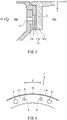
- FIG. 3 is a sectional view of another section of the flange laminated body 15 of FIG. 2 .
- FIG. 4 is a diagram showing the flange laminated body 15 when viewed from a direction indicated by an arrow IV in FIG. 3 .
- a contact surface of the combustor flange 11b which surface faces the case flange 13b includes cooling grooves G.
- the cooling grooves G are open outward in the radial direction Y of the combustor flange 11b and communicate with the low pressure space S2b.
- a length of the cooling groove G in the radial direction Y of the combustor flange 11 is longer than half a length of the combustor flange 11 in the radial direction Y
- the case flange 13b includes cooling jet holes H that are open toward the combustor flange 11b from the high pressure region S2a.
- the cooling jet holes H are communication spaces through which the high pressure region S2a communicates with the cooling grooves G.
- the cooling jet hole H is smaller in diameter than a bolt hole of the case flange 13b into which the bolt B is inserted.
- a passage axis of the cooling jet hole H is practically orthogonal to a bottom surface of the cooling groove G of the combustor flange 11b.
- the cooling jet hole H When viewed from a laminating direction (axial direction X) of the flange laminated body 15, the cooling jet hole H is arranged so as to be contained in the cooling groove G. At least one cooling jet hole G is arranged between two adjacent bolts B among the bolts B. In the example of FIG. 4 , the cooling jet holes G are arranged between two adjacent bolts B among the bolts B.
- the compressed air of the high pressure region S2a flows through the cooling jet holes H of the case flange 13b of the combustor case 13, collides with (the bottom surfaces of the cooling grooves G of) the combustor flange 11b at high pressure, and flows out from the cooling grooves G to the low pressure region S2b.
- the combustor flange 11b and the stationary blade unit flange 12b are cooled, and therefore, the increase in temperature of the case flange 13b by the heat from the high-temperature turbine nozzle 12ab is suppressed.
- the heat-resistant material does not have to be selected as the material of the combustor case 13, and an inexpensive material can be selected.
- the combustor flange 11b is sandwiched between the case flange 13b and the stationary blade unit flange 12b.
- the stationary blade unit flange 12b that increases in temperature by the heat from the turbine nozzle 12ab is separated from the case flange 13b by the combustor flange 11b. Therefore, the increase in temperature of the case flange 13b by the heat from the high-temperature turbine nozzle 12ab can be further suppressed.
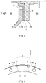
- FIG. 5 is a sectional view showing a flange laminated body 115 of Embodiment 2 and corresponding to FIG. 3 .
- FIG. 6 is a diagram showing the flange laminated body 115 when viewed from a direction indicated by an arrow VI in FIG. 5 .
- the same reference signs are used for the same components as Embodiment 1, and the repetition of the same explanation is avoided.
- cooling jet cutouts C are used instead of the cooling jet holes H ( FIG. 3 ).
- the case flange 113b includes the cooling jet cutouts C arranged at intervals in the circumferential direction Z.
- the cooling jet cutouts C are formed by locally cutting an end surface of the case flange 113 in the radial direction Y and are open toward a combustor flange 111b from the high pressure region S2a.
- the cooling jet cutout C overlaps a cooling groove G1 formed on a contact surface of the combustor flange 111b.
- a length of the cooling groove G1 in the radial direction Y of the combustor flange 11 is practically the same as a length of the combustor flange 11 in the radial direction Y but may be shorter than the length of the combustor flange 11 in the radial direction Y
- the compressed air of the high pressure region S2a flows through the cooling jet cutouts C of the case flange 113b, collides with the combustor flange 111b at high pressure, and flows out from the cooling grooves G1 to the low pressure region S2b.
- the combustor flange 111b and the stationary blade unit flange 12b are cooled, and therefore, the increase in temperature of the case flange 113b by the heat from the high-temperature turbine nozzle 12ab is suppressed. Since the other components are the same as those of Embodiment 1, explanations thereof are omitted.
- FIG. 7 is a sectional view showing a flange laminated body 215 of Embodiment 3 and corresponding to FIG. 3 .
- the same reference signs are used for the same components as Embodiment 1, and the repetition of the same explanation is avoided.
- cooling grooves G2 are located at not a combustor flange 211 but a case flange 213b.
- the cooling grooves G2 are formed on a contact surface of the case flange 213b which surface faces the combustor flange 211b.
- a contact surface of the combustor flange 211b which surface faces the case flange 213b is an entirely flat surface.
- the case flange 213b includes the cooling jet holes H that are open toward the combustor flange 211b from the high pressure region S2a.
- the cooling jet holes H are communication spaces through which the high pressure region S2a communicates with the cooling grooves G2.
- the passage axis of the cooling jet hole H is practically orthogonal to the contact surface of the combustor flange 211b.
- the compressed air of the high pressure region S2a flows through the cooling jet holes H of the case flange 213b, collides with the combustor flange 211b at high pressure, and flows out from the cooling grooves G2 to the low pressure region S2b.
- the combustor flange 211b and the stationary blade unit flange 12b are cooled, and therefore, the increase in temperature of the case flange 213b by the heat from the high-temperature turbine nozzle 12ab is suppressed.
- the contact surface of the combustor flange 211b which surface faces the case flange 213b does not have to be a flat surface, and cooling grooves may be additionally formed on the contact surface of the combustor flange 211b. Since the other components are the same as those of Embodiment 1, explanations thereof are omitted.
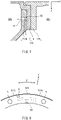
- FIG. 8 is a diagram showing a flange laminated body 315 of Embodiment 4 and corresponding to FIG. 4 .
- a cooling groove G3 formed on a contact surface of a case flange 313b or a contact surface of a combustor flange 311b extends not only in the radial direction Y of the flange laminated body 315 linearly but also in the circumferential direction Z of the flange laminated body 315.
- the cooling jet cutout C is shown, but the cooling jet hole H may be adopted.
- the present disclosure is not limited to the above-described embodiments, and modifications, additions, and eliminations may be made with respect to the configurations of the embodiments.
- some of components or methods in an embodiment may be applied to another embodiment, and some of components in an embodiment may be separated and arbitrarily extracted from the other components in the embodiment.
- the combustor flange 11b, 111b, 211b is sandwiched between the case flange 13b, 113b, 213b and the stationary blade unit flange 12b.
- the stationary blade unit flange 12b may be sandwiched between the case flange 13b, 113b, 213b and the combustor flange 11b, 111b, 211b.
Landscapes
- Engineering & Computer Science (AREA)
- Mechanical Engineering (AREA)
- General Engineering & Computer Science (AREA)
- Chemical & Material Sciences (AREA)
- Combustion & Propulsion (AREA)
- Turbine Rotor Nozzle Sealing (AREA)
Abstract
Description
- The present disclosure relates to a flange cooling structure of a gas turbine engine.
- A gas turbine engine in which a compressor, a combustor, and a turbine are arranged along a rotating shaft has been known.
-
- PTL 1:
Japanese Laid-Open Patent Application Publication No. 2012-145116 - PTL 2:
Japanese Laid-Open Patent Application Publication No. 2007-138933 - According to gas turbine engines, in some cases, cost reduction and space saving of the entire engine are extremely important, and therefore, cost reduction and space saving of each part are extremely important. Since heat-resistant materials mainly containing a nickel group, a cobalt group, and the like are high in material costs and low in machinability, manufacturing costs tend to be high. Therefore, a method of not selecting the heat-resistant materials as much as possible even for a high-temperature portion of the gas turbine engine is required.
- For example, a turbine nozzle is fastened through flanges to or is supported through a pin by a combustor case that is a comparatively low temperature part. In the case of the fastening through the flanges, to avoid the influence of heat from the turbine nozzle, a flange fastening structure is located away from the turbine nozzle by a certain distance, or the heat-resistant material is used as the material of the combustor case. In the former case, the occupied space of the engine increases by such extra distance. In the latter case, the material of the pin needs to be the heat-resistant material. In addition, the structure of the engine tends to be complex, and the engine tends to increase in size.
- A flange cooling structure of a gas turbine engine according to one aspect of the present disclosure is a flange cooling structure of a gas turbine engine in which a compressor, a combustor, and a turbine are arranged along a rotating shaft. The flange cooling structure includes: a first member including a first main body and a first flange, the first main body defining a first space, the first flange projecting from the first main body, heat of the combustor being transferred to the first member; a second member including a second main body and a second flange, the second main body defining a second space between the first main body and the second main body, the second flange projecting from the second main body, the second member being lower in temperature than the first member during operation of the gas turbine engine; and fasteners that fasten the first flange and the second flange to each other to form a flange laminated body that divides the second space. The second space is lower in temperature than the first space during the operation of the gas turbine engine. The second space includes a first region located at one side of the flange laminated body and a second region located at the other side of the flange laminated body. The first region is higher in pressure than the second region during the operation of the gas turbine engine. One of the first flange and the second flange is a high pressure flange that faces the first region. The other of the first flange and the second flange is a low pressure flange that faces the second region. A contact surface of the high pressure flange or a contact surface of the low pressure flange includes a cooling groove that communicates with the first region and the second region.
- According to the above configuration, while using the flange fastening structure for space saving and high rigidity, heat transfer from the high-temperature first member to the low-temperature second member is suppressed by air cooling at the flange contact surfaces. Therefore, the degree of freedom of the selection of the material of the second member improves, and this can reduce the manufacturing cost.
- According to one aspect of the present disclosure, the degree of freedom of the selection of the material of the second member improves, and this can reduce the manufacturing cost.
-
-
FIG. 1 is a schematic diagram of a gas turbine engine according toEmbodiment 1. -
FIG. 2 is a sectional view of major components of the gas turbine engine ofFIG. 1 . -
FIG. 3 is a sectional view of another section of a flange laminated body ofFIG. 2 . -
FIG. 4 is a diagram showing the flange laminated body when viewed from a direction indicated by an arrow IV inFIG. 3 . -
FIG. 5 is a sectional view showing the flange laminated body of Embodiment 2 and corresponding toFIG. 3 . -
FIG. 6 is a diagram showing the flange laminated body when viewed from a direction indicated by an arrow VI inFIG. 5 . -
FIG. 7 is a sectional view showing the flange laminated body ofEmbodiment 3 and corresponding toFIG. 3 . -
FIG. 8 is a diagram showing the flange laminated body ofEmbodiment 4 and corresponding toFIG. 4 . - Hereinafter, embodiments will be described with reference to the drawings.
-
FIG. 1 is a schematic diagram showing agas turbine engine 1 according toEmbodiment 1. As shown inFIG. 1 , thegas turbine engine 1 includes acompressor 3, acombustor 4, and aturbine 5 which are arranged along a rotating shaft 2. Air compressed by thecompressor 3 is combusted by thecombustor 4, and its combustion gas rotates theturbine 5. Thus, the rotating shaft 2 is driven. A direction in which an axis of the rotating shaft 2 extends is referred to as an axial direction X. A direction orthogonal to the axial direction X is referred to as a radial direction Y. A direction around the rotating shaft 2 is referred to as a circumferential direction Z. -
FIG. 2 is a sectional view of major components of thegas turbine engine 1 according toEmbodiment 1. As shown inFIG. 2 , thegas turbine engine 1 includes: a mainstream member 10 (first member) including ahousing 11 of thecombustor 4 and astationary blade unit 12 of theturbine 5; and acombustor case 13 arranged outside thecombustor 4. - The
housing 11 of thecombustor 4 includes: a housingmain body 11a (first main body) defining a combustion gas space S1 (first space); and acombustor flange 11b (first flange) projecting from the housingmain body 11a. Thehousing 11 is made of, for example, superalloy mainly containing a Fe group. - The
stationary blade unit 12 includes a stationary blade unitmain body 12a (first main body) and a stationaryblade unit flange 12b (first flange) projecting from the stationary blade unitmain body 12a. The stationary blade unitmain body 12a includes an inner tube 12aa, an outer tube 12ac located away from the inner tube 12aa in the radial direction Y, and a turbine nozzle 12ab disposed between the inner tube 12aa and the outer tube 12ac. The turbine nozzle 12ab communicates with the combustion gas space S1. The turbine nozzle 12ab increases in temperature by the combustion gas flowing from the combustion gas space S1 during the operation of thegas turbine engine 1. - The
stationary blade unit 12 is made of a material that is higher in heat resistance than thehousing 11. Thestationary blade unit 12 is made of a material that is higher in melting point than thehousing 11. Thehousing 11 is made of, for example, superalloy mainly containing a Fe group. Thestationary blade unit 12 is made of, for example, superalloy mainly containing a Ni group or superalloy mainly containing a Co group. - The
combustor case 13 includes a casemain body 13a (second main body) located away from themainstream member 10 in the radial direction Y; and acase flange 13b (second flange) projecting from the casemain body 13a. Thecombustor case 13 is lower in temperature than themainstream member 10 during the operation of thegas turbine engine 1. - The
case flange 13b, thecombustor flange 11b, and the stationaryblade unit flange 12b are laminated on each other in this order and are fastened to each other by plural pairs of bolts B and nuts N (fasteners) disposed at intervals in the circumferential direction Z. Thecase flange 13b, thecombustor flange 11b, and the stationaryblade unit flange 12b constitute a flange laminatedbody 15. - A compressed air space S2 (second space) through which the compressed air flowing from the
compressor 3 flows is located outside themainstream member 10. The compressed air space S2 is lower in temperature than the combustion gas space S1 during the operation of thegas turbine engine 1. The compressed air space S2 is divided by the flange laminatedbody 15 into a high pressure region S2a (first region) and a low pressure region S2b (second region). To be specific, the compressed air space S2 includes the high pressure region S2a located at one side of the flange laminatedbody 15 and the low pressure region S2b located at the other side of the flange laminatedbody 15. - The high pressure region S2a is defined by an inner surface of the
combustor case 13, an outer surface of thehousing 11, and the flange laminatedbody 15. The low pressure region S2b is defined by an outer surface of thecombustor case 13, an outer surface of thestationary blade unit 12, and the flange laminatedbody 15. The compressed air of the high pressure region S2a is supplied to thecombustor 4. The low pressure region S2b communicates with outside air. The high pressure region S2a is higher in pressure than the low pressure region S2b during the operation of thegas turbine engine 1. - The
case flange 13b is a high pressure flange that faces the high pressure region S2a. A group of thecombustor flange 11b and the stationaryblade unit flange 12b is a low pressure flange that faces the low pressure region S2b. Thecase flange 13b, thecombustor flange 11b, and the stationaryblade unit flange 12b are laminated on each other in this order from the high pressure region S2a toward the low pressure region S2b. To be specific, thecombustor flange 11b is sandwiched between thecase flange 13b and the stationaryblade unit flange 12b. -
FIG. 3 is a sectional view of another section of the flange laminatedbody 15 ofFIG. 2 .FIG. 4 is a diagram showing the flange laminatedbody 15 when viewed from a direction indicated by an arrow IV inFIG. 3 . As shown inFIGS. 3 and 4 , a contact surface of thecombustor flange 11b which surface faces thecase flange 13b includes cooling grooves G. The cooling grooves G are open outward in the radial direction Y of thecombustor flange 11b and communicate with the low pressure space S2b. A length of the cooling groove G in the radial direction Y of thecombustor flange 11 is longer than half a length of thecombustor flange 11 in the radial direction Y - The
case flange 13b includes cooling jet holes H that are open toward thecombustor flange 11b from the high pressure region S2a. The cooling jet holes H are communication spaces through which the high pressure region S2a communicates with the cooling grooves G. The cooling jet hole H is smaller in diameter than a bolt hole of thecase flange 13b into which the bolt B is inserted. A passage axis of the cooling jet hole H is practically orthogonal to a bottom surface of the cooling groove G of thecombustor flange 11b. - When viewed from a laminating direction (axial direction X) of the flange laminated
body 15, the cooling jet hole H is arranged so as to be contained in the cooling groove G. At least one cooling jet hole G is arranged between two adjacent bolts B among the bolts B. In the example ofFIG. 4 , the cooling jet holes G are arranged between two adjacent bolts B among the bolts B. - According to the above-described configuration, the compressed air of the high pressure region S2a flows through the cooling jet holes H of the
case flange 13b of thecombustor case 13, collides with (the bottom surfaces of the cooling grooves G of) thecombustor flange 11b at high pressure, and flows out from the cooling grooves G to the low pressure region S2b. With this, thecombustor flange 11b and the stationaryblade unit flange 12b are cooled, and therefore, the increase in temperature of thecase flange 13b by the heat from the high-temperature turbine nozzle 12ab is suppressed. To be specific, while using a flange fastening structure for space saving and high rigidity, heat transfer from the high-temperaturestationary blade unit 12 to the low-temperature combustor case 13 is suppressed by air cooling at the flange contact surfaces. Therefore, the heat-resistant material does not have to be selected as the material of thecombustor case 13, and an inexpensive material can be selected. - Moreover, the
combustor flange 11b is sandwiched between thecase flange 13b and the stationaryblade unit flange 12b. To be specific, the stationaryblade unit flange 12b that increases in temperature by the heat from the turbine nozzle 12ab is separated from thecase flange 13b by thecombustor flange 11b. Therefore, the increase in temperature of thecase flange 13b by the heat from the high-temperature turbine nozzle 12ab can be further suppressed. -
FIG. 5 is a sectional view showing a flangelaminated body 115 of Embodiment 2 and corresponding toFIG. 3 .FIG. 6 is a diagram showing the flange laminatedbody 115 when viewed from a direction indicated by an arrow VI inFIG. 5 . The same reference signs are used for the same components asEmbodiment 1, and the repetition of the same explanation is avoided. As shown inFIGS. 5 and 6 , in the flange laminatedbody 115 of Embodiment 2, cooling jet cutouts C are used instead of the cooling jet holes H (FIG. 3 ). - The
case flange 113b includes the cooling jet cutouts C arranged at intervals in the circumferential direction Z. The cooling jet cutouts C are formed by locally cutting an end surface of the case flange 113 in the radial direction Y and are open toward acombustor flange 111b from the high pressure region S2a. When viewed from the laminating direction (axial direction X) of the flange laminatedbody 15, the cooling jet cutout C overlaps a cooling groove G1 formed on a contact surface of thecombustor flange 111b. In the example ofFIG. 5 , a length of the cooling groove G1 in the radial direction Y of thecombustor flange 11 is practically the same as a length of thecombustor flange 11 in the radial direction Y but may be shorter than the length of thecombustor flange 11 in the radial direction Y - According to the above configuration, the compressed air of the high pressure region S2a flows through the cooling jet cutouts C of the
case flange 113b, collides with thecombustor flange 111b at high pressure, and flows out from the cooling grooves G1 to the low pressure region S2b. With this, thecombustor flange 111b and the stationaryblade unit flange 12b are cooled, and therefore, the increase in temperature of thecase flange 113b by the heat from the high-temperature turbine nozzle 12ab is suppressed. Since the other components are the same as those ofEmbodiment 1, explanations thereof are omitted. -
FIG. 7 is a sectional view showing a flangelaminated body 215 ofEmbodiment 3 and corresponding toFIG. 3 . The same reference signs are used for the same components asEmbodiment 1, and the repetition of the same explanation is avoided. As shown inFIG. 7 , in the flange laminatedbody 215 ofEmbodiment 3, cooling grooves G2 are located at not a combustor flange 211 but acase flange 213b. To be specific, the cooling grooves G2 are formed on a contact surface of thecase flange 213b which surface faces thecombustor flange 211b. A contact surface of thecombustor flange 211b which surface faces thecase flange 213b is an entirely flat surface. - The
case flange 213b includes the cooling jet holes H that are open toward thecombustor flange 211b from the high pressure region S2a. The cooling jet holes H are communication spaces through which the high pressure region S2a communicates with the cooling grooves G2. The passage axis of the cooling jet hole H is practically orthogonal to the contact surface of thecombustor flange 211b. - According to the above configuration, the compressed air of the high pressure region S2a flows through the cooling jet holes H of the
case flange 213b, collides with thecombustor flange 211b at high pressure, and flows out from the cooling grooves G2 to the low pressure region S2b. With this, thecombustor flange 211b and the stationaryblade unit flange 12b are cooled, and therefore, the increase in temperature of thecase flange 213b by the heat from the high-temperature turbine nozzle 12ab is suppressed. The contact surface of thecombustor flange 211b which surface faces thecase flange 213b does not have to be a flat surface, and cooling grooves may be additionally formed on the contact surface of thecombustor flange 211b. Since the other components are the same as those ofEmbodiment 1, explanations thereof are omitted. -
FIG. 8 is a diagram showing a flangelaminated body 315 ofEmbodiment 4 and corresponding toFIG. 4 . As shown inFIG. 8 , in the flange laminatedbody 315 ofEmbodiment 4, a cooling groove G3 formed on a contact surface of acase flange 313b or a contact surface of acombustor flange 311b extends not only in the radial direction Y of the flange laminatedbody 315 linearly but also in the circumferential direction Z of the flange laminatedbody 315. With this, the length of the cooling groove G3 can be increased, and therefore, the cooling effect can be improved. InFIG. 8 , the cooling jet cutout C is shown, but the cooling jet hole H may be adopted. - The present disclosure is not limited to the above-described embodiments, and modifications, additions, and eliminations may be made with respect to the configurations of the embodiments. For example, some of components or methods in an embodiment may be applied to another embodiment, and some of components in an embodiment may be separated and arbitrarily extracted from the other components in the embodiment. In the above embodiments, the
combustor flange case flange blade unit flange 12b. However, the stationaryblade unit flange 12b may be sandwiched between thecase flange combustor flange -
- 1
- gas turbine engine
- 2
- rotating shaft
- 3
- compressor
- 4
- combustor
- 5
- turbine
- 10
- mainstream member (first member)
- 11
- housing (first member) of combustor
- 11a
- housing main body (first main body)
- 11b
- combustor flange (first flange)
- 12
- stationary blade unit (first member)
- 12a
- stationary blade unit main body (first main body)
- 12aa
- inner tube
- 12ab
- turbine nozzle
- 12ac
- outer tube
- 12b
- stationary blade unit flange (first flange)
- 13
- combustor case (second member)
- 13a
- case main body (second main body)
- 13b
- case flange (second flange)
- 15
- flange laminated body
- 20
- flange cooling structure
- B
- bolt (fastener)
- C
- cooling jet cutout
- G
- cooling groove
- H
- cooling jet hole
- N
- nut (fastener)
- S1
- combustion gas space (first space)
- S2
- compressed air space (second space)
- S2a
- high pressure region (first region)
- S2b
- low pressure region (second region)
Claims (7)
- A flange cooling structure of a gas turbine engine in which a compressor, a combustor, and a turbine are arranged along a rotating shaft,
the flange cooling structure comprising:a first member including a first main body and a first flange, the first main body defining a first space, the first flange projecting from the first main body, heat of the combustor being transferred to the first member;a second member including a second main body and a second flange, the second main body defining a second space between the first main body and the second main body, the second flange projecting from the second main body, the second member being lower in temperature than the first member during operation of the gas turbine engine; andfasteners that fasten the first flange and the second flange to each other to form a flange laminated body that divides the second space, wherein:the second space is lower in temperature than the first space during the operation of the gas turbine engine;the second space includes a first region located at one side of the flange laminated body and a second region located at the other side of the flange laminated body;the first region is higher in pressure than the second region during the operation of the gas turbine engine;one of the first flange and the second flange is a high pressure flange that faces the first region;the other of the first flange and the second flange is a low pressure flange that faces the second region; anda contact surface of the high pressure flange or a contact surface of the low pressure flange includes a cooling groove that communicates with the first region and the second region. - The flange cooling structure according to claim 1, wherein the high pressure flange includes a communication space through which the first region communicates with the cooling groove.
- The flange cooling structure according to claim 2, wherein the communication space is at least one cooling jet hole or cutout that is open toward the low pressure flange from the first region.
- The flange cooling structure according to claim 3, wherein the cooling jet hole or the cutout is arranged between two adjacent fasteners among the fasteners.
- The flange cooling structure according to claim 4, wherein the at least one cooling jet hole or cutout comprises cooling jet holes or cutouts arranged between the two adjacent fasteners.
- The flange cooling structure according to any one of claims 1 to 5, wherein:the first member includes a housing of the combustor and a stationary blade unit of the turbine;the second member includes a combustor case arranged outside the combustor;the first flange includes a combustor flange of the combustor and a stationary blade unit flange of the stationary blade unit; andthe second flange includes a case flange of the combustor case.
- The flange cooling structure according to claim 6, wherein:the case flange, the combustor flange, and the stationary blade unit flange are laminated on each other in this order from the first region toward the second region;the cooling jet hole or the cutout is located at the case flange; andthe cooling groove is located on a contact surface of the case flange or a contact surface of the combustor flange.
Applications Claiming Priority (2)
| Application Number | Priority Date | Filing Date | Title |
|---|---|---|---|
| US202062978996P | 2020-02-20 | 2020-02-20 | |
| PCT/JP2021/006116 WO2021167001A1 (en) | 2020-02-20 | 2021-02-18 | Flange cooling structure for gas turbine engine |
Publications (3)
| Publication Number | Publication Date |
|---|---|
| EP4108898A1 true EP4108898A1 (en) | 2022-12-28 |
| EP4108898A4 EP4108898A4 (en) | 2024-03-13 |
| EP4108898B1 EP4108898B1 (en) | 2025-01-08 |
Family
ID=77391289
Family Applications (1)
| Application Number | Title | Priority Date | Filing Date |
|---|---|---|---|
| EP21757349.2A Active EP4108898B1 (en) | 2020-02-20 | 2021-02-18 | Flange cooling structure for gas turbine engine |
Country Status (4)
| Country | Link |
|---|---|
| US (1) | US11867079B2 (en) |
| EP (1) | EP4108898B1 (en) |
| JP (1) | JP7412529B2 (en) |
| WO (1) | WO2021167001A1 (en) |
Families Citing this family (1)
| Publication number | Priority date | Publication date | Assignee | Title |
|---|---|---|---|---|
| US11814977B1 (en) * | 2022-08-29 | 2023-11-14 | Rtx Corporation | Thermal conditioning of flange with secondary flow |
Family Cites Families (20)
| Publication number | Priority date | Publication date | Assignee | Title |
|---|---|---|---|---|
| GB1282142A (en) | 1969-03-29 | 1972-07-19 | Rolls Royce | Improvements in or relating to gas turbine engines |
| JPS59148445U (en) * | 1983-03-25 | 1984-10-04 | 株式会社日立製作所 | gas turbine casing |
| US5593277A (en) * | 1995-06-06 | 1997-01-14 | General Electric Company | Smart turbine shroud |
| US6916154B2 (en) * | 2003-04-29 | 2005-07-12 | Pratt & Whitney Canada Corp. | Diametrically energized piston ring |
| JP2006097585A (en) * | 2004-09-29 | 2006-04-13 | Mitsubishi Heavy Ind Ltd | Mounting structure for air separator and gas turbine provided with the same |
| US8517666B2 (en) | 2005-09-12 | 2013-08-27 | United Technologies Corporation | Turbine cooling air sealing |
| US7341429B2 (en) * | 2005-11-16 | 2008-03-11 | General Electric Company | Methods and apparatuses for cooling gas turbine engine rotor assemblies |
| US7870742B2 (en) | 2006-11-10 | 2011-01-18 | General Electric Company | Interstage cooled turbine engine |
| US7611324B2 (en) * | 2006-11-30 | 2009-11-03 | General Electric Company | Method and system to facilitate enhanced local cooling of turbine engines |
| FR2931873B1 (en) * | 2008-05-29 | 2010-08-20 | Snecma | A TURBINE DISK ASSEMBLY OF A GAS TURBINE ENGINE AND A BEARING BRIDGE SUPPORT CIRCUIT, COOLING CIRCUIT OF A TURBINE DISK OF SUCH AN ASSEMBLY. |
| US8459941B2 (en) * | 2009-06-15 | 2013-06-11 | General Electric Company | Mechanical joint for a gas turbine engine |
| US20130333388A1 (en) * | 2012-06-13 | 2013-12-19 | General Electric Company | Combustor liner cooling assembly for a gas turbine system |
| JP6069981B2 (en) * | 2012-09-10 | 2017-02-01 | 株式会社島津製作所 | Turbo molecular pump |
| GB201305432D0 (en) * | 2013-03-26 | 2013-05-08 | Rolls Royce Plc | A gas turbine engine cooling arrangement |
| DE102013226490A1 (en) * | 2013-12-18 | 2015-06-18 | Rolls-Royce Deutschland Ltd & Co Kg | Chilled flange connection of a gas turbine engine |
| JP2017057838A (en) * | 2015-09-18 | 2017-03-23 | 株式会社東芝 | Gas turbine cooling structure and gas turbine |
| PL416036A1 (en) * | 2016-02-04 | 2017-08-16 | General Electric Company | Flanged connection unit to be used in a turbocharged engine |
| GB201701380D0 (en) * | 2016-12-20 | 2017-03-15 | Rolls Royce Plc | A combustion chamber and a combustion chamber fuel injector seal |
| CN110573711B (en) * | 2017-09-27 | 2022-04-05 | 三菱重工发动机和增压器株式会社 | Turbine housing and supercharger with same |
| FR3084141B1 (en) * | 2018-07-19 | 2021-04-02 | Safran Aircraft Engines | SET FOR A TURBOMACHINE |
-
2021
- 2021-02-18 JP JP2022501967A patent/JP7412529B2/en active Active
- 2021-02-18 WO PCT/JP2021/006116 patent/WO2021167001A1/en not_active Ceased
- 2021-02-18 EP EP21757349.2A patent/EP4108898B1/en active Active
- 2021-02-18 US US17/800,056 patent/US11867079B2/en active Active
Also Published As
| Publication number | Publication date |
|---|---|
| WO2021167001A1 (en) | 2021-08-26 |
| EP4108898B1 (en) | 2025-01-08 |
| US20230080666A1 (en) | 2023-03-16 |
| JPWO2021167001A1 (en) | 2021-08-26 |
| JP7412529B2 (en) | 2024-01-12 |
| US11867079B2 (en) | 2024-01-09 |
| EP4108898A4 (en) | 2024-03-13 |
Similar Documents
| Publication | Publication Date | Title |
|---|---|---|
| US10138757B2 (en) | Bearing system for gas turbine engine | |
| US9200530B2 (en) | Radial position control of case supported structure | |
| US9896966B2 (en) | Tie rod for a gas turbine engine | |
| EP2177771B1 (en) | Scalable high pressure compressor variable vane actuation arm | |
| US12352440B2 (en) | Combustor assembly for a turbine engine | |
| US7882696B2 (en) | Integrated support and mixer for turbo machinery | |
| EP3032176B1 (en) | Fuel injector guide(s) for a turbine engine combustor | |
| EP2964899B1 (en) | Structure and method for providing compliance and sealing between ceramic and metallic structures | |
| US10941937B2 (en) | Combustor liner with gasket for gas turbine engine | |
| US20220268443A1 (en) | Flow control wall for heat engine | |
| US9249678B2 (en) | Transition duct for a gas turbine | |
| US10801350B2 (en) | Actively cooled engine assembly with ceramic matrix composite components | |
| US10385713B2 (en) | Seal assembly for gas turbine engines | |
| JP2001355737A (en) | Surface following brush seal | |
| US11555416B2 (en) | Rotor stack bushing with adaptive temperature metering for a gas turbine engine | |
| EP4108898B1 (en) | Flange cooling structure for gas turbine engine | |
| US7131814B2 (en) | Cooling arrangement | |
| US9366185B2 (en) | Flexible connection between a wall and a case of a turbine engine | |
| US11466591B2 (en) | Reduced radial clearance seal system | |
| EP3282101A1 (en) | Shim for gas turbine engine | |
| US10648670B2 (en) | Swirler assembly for a turbine engine | |
| EP4641091A1 (en) | Gas turbine combustor | |
| US11891898B2 (en) | Seal assemblies for turbine engines | |
| US10690345B2 (en) | Combustor assemblies for use in turbine engines and methods of assembling same | |
| US10941669B2 (en) | Diffuser case support structure |
Legal Events
| Date | Code | Title | Description |
|---|---|---|---|
| STAA | Information on the status of an ep patent application or granted ep patent |
Free format text: STATUS: THE INTERNATIONAL PUBLICATION HAS BEEN MADE |
|
| PUAI | Public reference made under article 153(3) epc to a published international application that has entered the european phase |
Free format text: ORIGINAL CODE: 0009012 |
|
| STAA | Information on the status of an ep patent application or granted ep patent |
Free format text: STATUS: REQUEST FOR EXAMINATION WAS MADE |
|
| 17P | Request for examination filed |
Effective date: 20220823 |
|
| AK | Designated contracting states |
Kind code of ref document: A1 Designated state(s): AL AT BE BG CH CY CZ DE DK EE ES FI FR GB GR HR HU IE IS IT LI LT LU LV MC MK MT NL NO PL PT RO RS SE SI SK SM TR |
|
| DAV | Request for validation of the european patent (deleted) | ||
| DAX | Request for extension of the european patent (deleted) | ||
| A4 | Supplementary search report drawn up and despatched |
Effective date: 20240209 |
|
| RIC1 | Information provided on ipc code assigned before grant |
Ipc: F23R 3/42 20060101ALI20240205BHEP Ipc: F01D 25/24 20060101ALI20240205BHEP Ipc: F02C 7/18 20060101AFI20240205BHEP |
|
| GRAP | Despatch of communication of intention to grant a patent |
Free format text: ORIGINAL CODE: EPIDOSNIGR1 |
|
| STAA | Information on the status of an ep patent application or granted ep patent |
Free format text: STATUS: GRANT OF PATENT IS INTENDED |
|
| INTG | Intention to grant announced |
Effective date: 20241004 |
|
| GRAS | Grant fee paid |
Free format text: ORIGINAL CODE: EPIDOSNIGR3 |
|
| GRAA | (expected) grant |
Free format text: ORIGINAL CODE: 0009210 |
|
| STAA | Information on the status of an ep patent application or granted ep patent |
Free format text: STATUS: THE PATENT HAS BEEN GRANTED |
|
| AK | Designated contracting states |
Kind code of ref document: B1 Designated state(s): AL AT BE BG CH CY CZ DE DK EE ES FI FR GB GR HR HU IE IS IT LI LT LU LV MC MK MT NL NO PL PT RO RS SE SI SK SM TR |
|
| REG | Reference to a national code |
Ref country code: GB Ref legal event code: FG4D |
|
| REG | Reference to a national code |
Ref country code: CH Ref legal event code: EP |
|
| REG | Reference to a national code |
Ref country code: DE Ref legal event code: R096 Ref document number: 602021024705 Country of ref document: DE |
|
| REG | Reference to a national code |
Ref country code: IE Ref legal event code: FG4D |
|
| PGFP | Annual fee paid to national office [announced via postgrant information from national office to epo] |
Ref country code: AT Payment date: 20250417 Year of fee payment: 5 |
|
| REG | Reference to a national code |
Ref country code: LT Ref legal event code: MG9D |
|
| REG | Reference to a national code |
Ref country code: NL Ref legal event code: MP Effective date: 20250108 |
|
| REG | Reference to a national code |
Ref country code: AT Ref legal event code: MK05 Ref document number: 1758460 Country of ref document: AT Kind code of ref document: T Effective date: 20250108 |
|
| PG25 | Lapsed in a contracting state [announced via postgrant information from national office to epo] |
Ref country code: NL Free format text: LAPSE BECAUSE OF FAILURE TO SUBMIT A TRANSLATION OF THE DESCRIPTION OR TO PAY THE FEE WITHIN THE PRESCRIBED TIME-LIMIT Effective date: 20250108 |
|
| PG25 | Lapsed in a contracting state [announced via postgrant information from national office to epo] |
Ref country code: RS Free format text: LAPSE BECAUSE OF FAILURE TO SUBMIT A TRANSLATION OF THE DESCRIPTION OR TO PAY THE FEE WITHIN THE PRESCRIBED TIME-LIMIT Effective date: 20250408 |
|
| PG25 | Lapsed in a contracting state [announced via postgrant information from national office to epo] |
Ref country code: FI Free format text: LAPSE BECAUSE OF FAILURE TO SUBMIT A TRANSLATION OF THE DESCRIPTION OR TO PAY THE FEE WITHIN THE PRESCRIBED TIME-LIMIT Effective date: 20250108 |
|
| PG25 | Lapsed in a contracting state [announced via postgrant information from national office to epo] |
Ref country code: PL Free format text: LAPSE BECAUSE OF FAILURE TO SUBMIT A TRANSLATION OF THE DESCRIPTION OR TO PAY THE FEE WITHIN THE PRESCRIBED TIME-LIMIT Effective date: 20250108 |
|
| PG25 | Lapsed in a contracting state [announced via postgrant information from national office to epo] |
Ref country code: ES Free format text: LAPSE BECAUSE OF FAILURE TO SUBMIT A TRANSLATION OF THE DESCRIPTION OR TO PAY THE FEE WITHIN THE PRESCRIBED TIME-LIMIT Effective date: 20250108 |
|
| PG25 | Lapsed in a contracting state [announced via postgrant information from national office to epo] |
Ref country code: NO Free format text: LAPSE BECAUSE OF FAILURE TO SUBMIT A TRANSLATION OF THE DESCRIPTION OR TO PAY THE FEE WITHIN THE PRESCRIBED TIME-LIMIT Effective date: 20250408 Ref country code: IS Free format text: LAPSE BECAUSE OF FAILURE TO SUBMIT A TRANSLATION OF THE DESCRIPTION OR TO PAY THE FEE WITHIN THE PRESCRIBED TIME-LIMIT Effective date: 20250508 |
|
| PG25 | Lapsed in a contracting state [announced via postgrant information from national office to epo] |
Ref country code: HR Free format text: LAPSE BECAUSE OF FAILURE TO SUBMIT A TRANSLATION OF THE DESCRIPTION OR TO PAY THE FEE WITHIN THE PRESCRIBED TIME-LIMIT Effective date: 20250108 |
|
| PG25 | Lapsed in a contracting state [announced via postgrant information from national office to epo] |
Ref country code: PT Free format text: LAPSE BECAUSE OF FAILURE TO SUBMIT A TRANSLATION OF THE DESCRIPTION OR TO PAY THE FEE WITHIN THE PRESCRIBED TIME-LIMIT Effective date: 20250508 Ref country code: LV Free format text: LAPSE BECAUSE OF FAILURE TO SUBMIT A TRANSLATION OF THE DESCRIPTION OR TO PAY THE FEE WITHIN THE PRESCRIBED TIME-LIMIT Effective date: 20250108 |
|
| PG25 | Lapsed in a contracting state [announced via postgrant information from national office to epo] |
Ref country code: GR Free format text: LAPSE BECAUSE OF FAILURE TO SUBMIT A TRANSLATION OF THE DESCRIPTION OR TO PAY THE FEE WITHIN THE PRESCRIBED TIME-LIMIT Effective date: 20250409 Ref country code: BG Free format text: LAPSE BECAUSE OF FAILURE TO SUBMIT A TRANSLATION OF THE DESCRIPTION OR TO PAY THE FEE WITHIN THE PRESCRIBED TIME-LIMIT Effective date: 20250108 |
|
| PG25 | Lapsed in a contracting state [announced via postgrant information from national office to epo] |
Ref country code: AT Free format text: LAPSE BECAUSE OF FAILURE TO SUBMIT A TRANSLATION OF THE DESCRIPTION OR TO PAY THE FEE WITHIN THE PRESCRIBED TIME-LIMIT Effective date: 20250108 |
|
| PG25 | Lapsed in a contracting state [announced via postgrant information from national office to epo] |
Ref country code: SE Free format text: LAPSE BECAUSE OF FAILURE TO SUBMIT A TRANSLATION OF THE DESCRIPTION OR TO PAY THE FEE WITHIN THE PRESCRIBED TIME-LIMIT Effective date: 20250108 |
|
| REG | Reference to a national code |
Ref country code: CH Ref legal event code: PL |
|
| PG25 | Lapsed in a contracting state [announced via postgrant information from national office to epo] |
Ref country code: SM Free format text: LAPSE BECAUSE OF FAILURE TO SUBMIT A TRANSLATION OF THE DESCRIPTION OR TO PAY THE FEE WITHIN THE PRESCRIBED TIME-LIMIT Effective date: 20250108 |
|
| REG | Reference to a national code |
Ref country code: DE Ref legal event code: R097 Ref document number: 602021024705 Country of ref document: DE |
|
| PG25 | Lapsed in a contracting state [announced via postgrant information from national office to epo] |
Ref country code: DK Free format text: LAPSE BECAUSE OF FAILURE TO SUBMIT A TRANSLATION OF THE DESCRIPTION OR TO PAY THE FEE WITHIN THE PRESCRIBED TIME-LIMIT Effective date: 20250108 |
|
| PG25 | Lapsed in a contracting state [announced via postgrant information from national office to epo] |
Ref country code: MC Free format text: LAPSE BECAUSE OF FAILURE TO SUBMIT A TRANSLATION OF THE DESCRIPTION OR TO PAY THE FEE WITHIN THE PRESCRIBED TIME-LIMIT Effective date: 20250108 |
|
| PG25 | Lapsed in a contracting state [announced via postgrant information from national office to epo] |
Ref country code: LU Free format text: LAPSE BECAUSE OF NON-PAYMENT OF DUE FEES Effective date: 20250218 |
|
| PG25 | Lapsed in a contracting state [announced via postgrant information from national office to epo] |
Ref country code: CH Free format text: LAPSE BECAUSE OF NON-PAYMENT OF DUE FEES Effective date: 20250228 |
|
| PG25 | Lapsed in a contracting state [announced via postgrant information from national office to epo] |
Ref country code: EE Free format text: LAPSE BECAUSE OF FAILURE TO SUBMIT A TRANSLATION OF THE DESCRIPTION OR TO PAY THE FEE WITHIN THE PRESCRIBED TIME-LIMIT Effective date: 20250108 Ref country code: CZ Free format text: LAPSE BECAUSE OF FAILURE TO SUBMIT A TRANSLATION OF THE DESCRIPTION OR TO PAY THE FEE WITHIN THE PRESCRIBED TIME-LIMIT Effective date: 20250108 |
|
| PG25 | Lapsed in a contracting state [announced via postgrant information from national office to epo] |
Ref country code: RO Free format text: LAPSE BECAUSE OF FAILURE TO SUBMIT A TRANSLATION OF THE DESCRIPTION OR TO PAY THE FEE WITHIN THE PRESCRIBED TIME-LIMIT Effective date: 20250108 |
|
| PG25 | Lapsed in a contracting state [announced via postgrant information from national office to epo] |
Ref country code: SK Free format text: LAPSE BECAUSE OF FAILURE TO SUBMIT A TRANSLATION OF THE DESCRIPTION OR TO PAY THE FEE WITHIN THE PRESCRIBED TIME-LIMIT Effective date: 20250108 |
|
| PLBE | No opposition filed within time limit |
Free format text: ORIGINAL CODE: 0009261 |
|
| STAA | Information on the status of an ep patent application or granted ep patent |
Free format text: STATUS: NO OPPOSITION FILED WITHIN TIME LIMIT |
|
| REG | Reference to a national code |
Ref country code: BE Ref legal event code: MM Effective date: 20250228 |
|
| 26N | No opposition filed |
Effective date: 20251009 |
|
| PG25 | Lapsed in a contracting state [announced via postgrant information from national office to epo] |
Ref country code: BE Free format text: LAPSE BECAUSE OF NON-PAYMENT OF DUE FEES Effective date: 20250228 |
|
| PG25 | Lapsed in a contracting state [announced via postgrant information from national office to epo] |
Ref country code: IE Free format text: LAPSE BECAUSE OF NON-PAYMENT OF DUE FEES Effective date: 20250218 |
|
| PG25 | Lapsed in a contracting state [announced via postgrant information from national office to epo] |
Ref country code: IT Free format text: LAPSE BECAUSE OF FAILURE TO SUBMIT A TRANSLATION OF THE DESCRIPTION OR TO PAY THE FEE WITHIN THE PRESCRIBED TIME-LIMIT Effective date: 20250108 |
|
| PGFP | Annual fee paid to national office [announced via postgrant information from national office to epo] |
Ref country code: GB Payment date: 20260107 Year of fee payment: 6 |
|
| PGFP | Annual fee paid to national office [announced via postgrant information from national office to epo] |
Ref country code: DE Payment date: 20260107 Year of fee payment: 6 |
|
| PGFP | Annual fee paid to national office [announced via postgrant information from national office to epo] |
Ref country code: FR Payment date: 20260107 Year of fee payment: 6 |
|
| PG25 | Lapsed in a contracting state [announced via postgrant information from national office to epo] |
Ref country code: CY Free format text: LAPSE BECAUSE OF FAILURE TO SUBMIT A TRANSLATION OF THE DESCRIPTION OR TO PAY THE FEE WITHIN THE PRESCRIBED TIME-LIMIT Effective date: 20250108 |
|
| PG25 | Lapsed in a contracting state [announced via postgrant information from national office to epo] |
Ref country code: LT Free format text: LAPSE BECAUSE OF FAILURE TO SUBMIT A TRANSLATION OF THE DESCRIPTION OR TO PAY THE FEE WITHIN THE PRESCRIBED TIME-LIMIT Effective date: 20250108 |
|
| PG25 | Lapsed in a contracting state [announced via postgrant information from national office to epo] |
Ref country code: TR Free format text: LAPSE BECAUSE OF FAILURE TO SUBMIT A TRANSLATION OF THE DESCRIPTION OR TO PAY THE FEE WITHIN THE PRESCRIBED TIME-LIMIT Effective date: 20250108 |