EP4108616A1 - Sheet stacking equipment - Google Patents
Sheet stacking equipment Download PDFInfo
- Publication number
- EP4108616A1 EP4108616A1 EP22179951.3A EP22179951A EP4108616A1 EP 4108616 A1 EP4108616 A1 EP 4108616A1 EP 22179951 A EP22179951 A EP 22179951A EP 4108616 A1 EP4108616 A1 EP 4108616A1
- Authority
- EP
- European Patent Office
- Prior art keywords
- sheets
- stack
- belts
- equipment
- stacking
- Prior art date
- Legal status (The legal status is an assumption and is not a legal conclusion. Google has not performed a legal analysis and makes no representation as to the accuracy of the status listed.)
- Granted
Links
Images





Classifications
-
- B—PERFORMING OPERATIONS; TRANSPORTING
- B65—CONVEYING; PACKING; STORING; HANDLING THIN OR FILAMENTARY MATERIAL
- B65H—HANDLING THIN OR FILAMENTARY MATERIAL, e.g. SHEETS, WEBS, CABLES
- B65H29/00—Delivering or advancing articles from machines; Advancing articles to or into piles
- B65H29/24—Delivering or advancing articles from machines; Advancing articles to or into piles by air blast or suction apparatus
- B65H29/241—Suction devices
- B65H29/242—Suction bands or belts
-
- B—PERFORMING OPERATIONS; TRANSPORTING
- B65—CONVEYING; PACKING; STORING; HANDLING THIN OR FILAMENTARY MATERIAL
- B65H—HANDLING THIN OR FILAMENTARY MATERIAL, e.g. SHEETS, WEBS, CABLES
- B65H31/00—Pile receivers
- B65H31/04—Pile receivers with movable end support arranged to recede as pile accumulates
- B65H31/08—Pile receivers with movable end support arranged to recede as pile accumulates the articles being piled one above another
- B65H31/10—Pile receivers with movable end support arranged to recede as pile accumulates the articles being piled one above another and applied at the top of the pile
-
- B—PERFORMING OPERATIONS; TRANSPORTING
- B65—CONVEYING; PACKING; STORING; HANDLING THIN OR FILAMENTARY MATERIAL
- B65H—HANDLING THIN OR FILAMENTARY MATERIAL, e.g. SHEETS, WEBS, CABLES
- B65H31/00—Pile receivers
- B65H31/04—Pile receivers with movable end support arranged to recede as pile accumulates
-
- B—PERFORMING OPERATIONS; TRANSPORTING
- B65—CONVEYING; PACKING; STORING; HANDLING THIN OR FILAMENTARY MATERIAL
- B65H—HANDLING THIN OR FILAMENTARY MATERIAL, e.g. SHEETS, WEBS, CABLES
- B65H31/00—Pile receivers
- B65H31/30—Arrangements for removing completed piles
- B65H31/3054—Arrangements for removing completed piles by moving the surface supporting the lowermost article of the pile, e.g. by using belts or rollers
-
- B—PERFORMING OPERATIONS; TRANSPORTING
- B65—CONVEYING; PACKING; STORING; HANDLING THIN OR FILAMENTARY MATERIAL
- B65H—HANDLING THIN OR FILAMENTARY MATERIAL, e.g. SHEETS, WEBS, CABLES
- B65H31/00—Pile receivers
- B65H31/34—Apparatus for squaring-up piled articles
-
- B—PERFORMING OPERATIONS; TRANSPORTING
- B65—CONVEYING; PACKING; STORING; HANDLING THIN OR FILAMENTARY MATERIAL
- B65H—HANDLING THIN OR FILAMENTARY MATERIAL, e.g. SHEETS, WEBS, CABLES
- B65H31/00—Pile receivers
- B65H31/34—Apparatus for squaring-up piled articles
- B65H31/36—Auxiliary devices for contacting each article with a front stop as it is piled
-
- B—PERFORMING OPERATIONS; TRANSPORTING
- B65—CONVEYING; PACKING; STORING; HANDLING THIN OR FILAMENTARY MATERIAL
- B65H—HANDLING THIN OR FILAMENTARY MATERIAL, e.g. SHEETS, WEBS, CABLES
- B65H33/00—Forming counted batches in delivery pile or stream of articles
- B65H33/06—Forming counted batches in delivery pile or stream of articles by displacing articles to define batches
- B65H33/08—Displacing whole batches, e.g. forming stepped piles
-
- B—PERFORMING OPERATIONS; TRANSPORTING
- B65—CONVEYING; PACKING; STORING; HANDLING THIN OR FILAMENTARY MATERIAL
- B65H—HANDLING THIN OR FILAMENTARY MATERIAL, e.g. SHEETS, WEBS, CABLES
- B65H2301/00—Handling processes for sheets or webs
- B65H2301/40—Type of handling process
- B65H2301/42—Piling, depiling, handling piles
- B65H2301/421—Forming a pile
- B65H2301/4219—Forming a pile forming a pile in which articles are offset from each other, e.g. forming stepped pile
- B65H2301/42194—Forming a pile forming a pile in which articles are offset from each other, e.g. forming stepped pile forming a pile in which articles are offset from each other in the delivery direction
-
- B—PERFORMING OPERATIONS; TRANSPORTING
- B65—CONVEYING; PACKING; STORING; HANDLING THIN OR FILAMENTARY MATERIAL
- B65H—HANDLING THIN OR FILAMENTARY MATERIAL, e.g. SHEETS, WEBS, CABLES
- B65H2406/00—Means using fluid
- B65H2406/30—Suction means
- B65H2406/32—Suction belts
- B65H2406/323—Overhead suction belt, i.e. holding material against gravity
-
- B—PERFORMING OPERATIONS; TRANSPORTING
- B65—CONVEYING; PACKING; STORING; HANDLING THIN OR FILAMENTARY MATERIAL
- B65H—HANDLING THIN OR FILAMENTARY MATERIAL, e.g. SHEETS, WEBS, CABLES
- B65H2511/00—Dimensions; Position; Numbers; Identification; Occurrences
- B65H2511/10—Size; Dimensions
- B65H2511/15—Height, e.g. of stack
-
- B—PERFORMING OPERATIONS; TRANSPORTING
- B65—CONVEYING; PACKING; STORING; HANDLING THIN OR FILAMENTARY MATERIAL
- B65H—HANDLING THIN OR FILAMENTARY MATERIAL, e.g. SHEETS, WEBS, CABLES
- B65H2553/00—Sensing or detecting means
- B65H2553/40—Sensing or detecting means using optical, e.g. photographic, elements
- B65H2553/44—Involving light guide, e.g. optical fibres
-
- B—PERFORMING OPERATIONS; TRANSPORTING
- B65—CONVEYING; PACKING; STORING; HANDLING THIN OR FILAMENTARY MATERIAL
- B65H—HANDLING THIN OR FILAMENTARY MATERIAL, e.g. SHEETS, WEBS, CABLES
- B65H2701/00—Handled material; Storage means
- B65H2701/10—Handled articles or webs
- B65H2701/11—Dimensional aspect of article or web
- B65H2701/113—Size
- B65H2701/1131—Size of sheets
- B65H2701/11312—Size of sheets large formats, i.e. above A3
-
- B—PERFORMING OPERATIONS; TRANSPORTING
- B65—CONVEYING; PACKING; STORING; HANDLING THIN OR FILAMENTARY MATERIAL
- B65H—HANDLING THIN OR FILAMENTARY MATERIAL, e.g. SHEETS, WEBS, CABLES
- B65H2801/00—Application field
- B65H2801/03—Image reproduction devices
- B65H2801/21—Industrial-size printers, e.g. rotary printing press
Definitions
- the present invention relates to an equipment for stacking paper sheets.
- the invention relates to an equipment for stacking sheets comprising a stack support for sheets in vertical stacking, input rollers for introducing and feeding sheets along a given direction, a plurality of extended transport belts with lower branches disposed above the stack support, a compensation mechanism for modifying the height of the stack and wherein the transport belts are motorized for shifting entering sheets with the lower branches and depositing the sheets on the stack support or on stacked sheets, as for the introductory portion of claim 1.
- Equipment of this type for example represented in the patent US 8,141,869 of Lasermax Roll System , are used for post-treatments of printed sheets.
- the transport belts cause the entering sheets to slide onto the last sheet of the forming stack until the arrest.
- problems arise due to the difference in smoothness existing between printed sheets and unprinted sheets. This can cause the formation of bulges, in particular in the arrest area, which prevent an orderly stacking and with risk of jamming, especially in the case of stacking equipment at high operating speed, for example of the order of 250 m/min.
- Similar problems arise in the case of the use of uncoated sheets having different characteristics from sheet to sheet and/or to be stacked together with sheets of coated paper.
- the sheet stacking equipment comprises an arrest member for the entering sheets, a pressure member for the stack being formed and a sensing device for the height of the stack being formed.
- the arrest member is designated for arresting the entering sheets;
- the pressing member is adjacent to the arrest member and operates on the last sheet of the stack in an area adjacent to the leading edge with stabilizing function, wherein the pressing member comprises a pressing cross member having a lower surface of contrast for the stack, and wherein the cross member operates on the pressing area of the last sheet of the stack with its lower surface, according to the characteristic portion of claim 1.
- the sheet stacking equipment comprises one or more ducts connected to a vacuum source, arranged transversally above the lower branches of the transport belts and with guide areas for the belt branches and a arrest member arranged downstream of the duct or ducts for arresting the entering and stacking sheets.
- the duct or ducts have openings in correspondence with the guide areas and the transport belts have longitudinal holes for ensuring a suction action on the entering sheets through said holes with traction by adherence of the sheets by the transport belts.
- the transport belts comprise a group of belts having a low coefficient of friction and a group of belts having a medium coefficient of friction, as for the characteristic portion of claim 12.
- the reference numeral 21 designates an equipment for stacking paper sheets 22 which includes a bodywork 23 and a frame with two sides 24 and 26, a front with an input gate 27 of the bodywork 23 and a respective rear with an output gate 28.
- the stacking equipment 21, through the gate 27, receives the sheets 22 horizontally from an external feeding apparatus along a feed direction "F" and, after stacking, sends a stack 29 of superimposed sheets, through the gate 28, to an external user apparatus for subsequent treatments.
- the paper sheets 22 are fed by a cutter "CM”, while the stack 29 is delivered to a conveyor belt “CB” for delivery to the user apparatus.
- the sheet stacking equipment 21 comprises an alignment section 31, a stacking and delivering section 32, respectively on the front and on the back, an electronic control unit 33, a push-button panel 34 and sensor elements, not shown, arranged along the internal path of the sheets.
- the sensor elements are functionally connected to the electronic unit 33 for counting the sheets to be stacked and for detecting some operating conditions and anomalies.
- the equipment 21 further lodges, in a lower part, a vacuum pump 36 and, optionally, a compressed air generator 37 in case an external compressed air source is not available.
- the equipment 21 is controlled by the feeding apparatus "CM", and the operating controls are carried out, for example, by means of a touch screen "CD" of the cutter "CM".
- the alignment section 31 is disposed in an upper part of the bodywork 23 and has a front projecting part defining the input gate 27 and with a horizontal receiving surface for the sheets 22.
- a series of alignment rollers 38 mounted on a frame 39, operate above the receiving surface to align, according to predetermined rules, the edges of the sheets 22, and of side by side sheets.
- the aligned sheets 22 are then delivered, coplanar with the receiving surface, by a pair of delivery rollers 40 along the fed direction "F" toward the stacking and delivering section 32, with adequate spacing between sheet and sheet.
- the frame 39 is hinged on the side 26 of the equipment and has the possibility of opening for an easy access to the receiving surface.
- the alignment section 31 is functionally of a known type and, for simplicity, the operational description thereof is omitted here.
- the stacking and delivering section 32 is constituted by a transport and storage group 41 adjacent to the alignment section 31 and an accumulation and delivery group 42 disposed below the group 41.
- the transport and storage group 41 comprises input rollers 43 downstream of the delivery rollers 40 and transport belts 44 for receiving and positioning the entering sheets above the stack 29.
- the accumulation and delivery group 42 includes a stack support 46 for receiving the sheets in stacking and a compensation mechanism 47 for vertically moving the stack support 46.
- the input rollers 43 are in mutual engagement on a horizontal geometric introduction plane "IP", coplanar with the receiving surface of the alignment section 31.
- the input rollers 43 are driven through belts and pulleys by an introduction motor 48 controlled by the electronic unit 33 to advance in the feed direction "F" the sheets 22 emerging from the delivery rollers 40.
- the transport belts 44 are of the flat type, of an extended shape and present respective lower horizontal branches 49, positioned in parallel above the stack support 46 and which define with their outer surface a transport surface "TS".
- the belts 44 are motorized for dragging the entering sheets with the lower branches 49 and depositing the sheets on the stack support 46 or on a last sheet of the stack 29 being formed, as will be described below.
- the sheet stacking equipment 21 comprises in the transport and storage group 41 a functional block 50 which includes an arrest member 51 for the entering sheets 22, a pressing member 52 for the stack 29 being formed, arranged upstream of the arrest member, and a sensing device 53 for the last sheet of the stack.
- the functional block 50 ( Figs. 1 , 3 and 5 ) comprises a transversal support plate 54, substantially vertical, on which the arrest member 51, the pressing member 52 and the sensing device 53 are transversally mounted.
- the plate 54 is provided at the sides with two slides 54r and 541 which are coupled, in a sliding manner and possibility of locking, with two lateral guides 56r and 561 fixed on the frame of the equipment 21.
- the arrest member 51 can be positioned according to the length of the sheets 22 to be stacked at a convenient distance from the input rollers 43, greater than the length of the sheets 22.
- the arrest member 51 defines a vertical alignment plane "AP" of the stack 29 and it is designated for arresting the moving sheets 22 to be stacked.
- the sheets 22 advance by the combined action of the input rollers 43 and the transport belts 44.
- the pressing member 52 operates on the last sheet of the stack 29 with stabilizing function.
- the sensing device 53 is interlocked with the compensation mechanism 47 to ensure optimal conditions for stacking regardless of the number of stacked sheets. This, for example and in a conventional manner, by maintaining constant the height, indicated "H", between the introduction plane "IP” and the last sheet of the stack 29 or between the introduction plane "IP” and the surface of the stack support 46 in absence of sheets.
- the input rollers 43 comprise in particular a driving roller 56 and a contrast roller 57, which are arranged in a tangential condition above and below the plane "IP".
- the transport belts 44 are stretched between the driving roller 56, a rear roller 58, upper deflection rollers 59 and 60, respectively front and rear, and a lower front deflection roller 61.
- the deflection rollers 59 and 60 form the upper branches, indicated by 63, of the transport belts 44, while the deflection roller 61 and the rear roller 58 form the lower branches 49 with the transport surface "TS".
- the branches 63 and the branches 49 are spaced apart so as to house mechanisms of the transport and storage group 41 including the pressing member 52 and the arrest member 51.
- the deflection rollers 59 and 61 are arranged downstream of the driving roller 56, while the deflection roller 60 is arranged upstream of the rear roller 58 and downstream of the arrest member 51.
- the lower branches 49 of the transport belts 44 are arranged at a distance in height from the plane "IP" lower than the height "H", so as to leave a space “G” between the transport surface "TS” of the branches 49 and the stack support 46 or between the transport surface "TS” and the last sheet of the stack 29.
- the space “G” is, for example, included between 0.2 and 0.8mm, such as to allow an easy passage of the sheets 22 to be stacked.
- the compensation mechanism 47 regulates the height of the support 46 between a series of operating positions in which the height "H” is kept substantially constant. Consequently, also the space “G” between the transport surface "TS” and the last sheet of the stack 29 or the surface of the stack support, in absence of sheets is maintained constant.
- the driving roller 56 defines, in a transversal direction, engagement seats for the transport belts 44, which are alternated with support seats for driving rings 64 of friction dragging for the sheets 22, and in which the engagement seats are for example made of elastomeric material.
- the contrast roller 57 is also made of elastomeric material.
- the driving roller 56 is driven in rotation trough pulleys and belts by the introduction motor 48 for a dragging speed of the transport belts 44 slightly higher than the feeding speed of the sheets 22 emerging from the delivery rollers 40.
- the lower deflection roller 61 constitutes an insertion roller for the entering sheets 22 and defines in a transversal direction guide seats for the transport belts 44 alternated with support seats for elastomeric rings 67 of friction dragging for the sheets 22.
- the deflection roller 61 determines belt portions 68 of the transport belts 44 included between the driving roller 56 and the roller 61 itself, inclined downwards, for guiding the leading edges of the sheets 22 emerging from the input rollers 43.
- Flexible detachment lugs 69 are interposed between the belt portions 68 and the end portions, in slight interference with the path of the sheets 22, for facilitating the separation of the trailing edges of the sheets 22, jointly with the leaving of the sheets from the input rollers 43.
- the pressing member 52 ( Figs. 3 , 5 and 5b ) comprises a pressing crossbar 71 on which a pneumatic actuator 72 operates.
- the crossbar 71 is contiguous to the arrest member 51 and extends in cross-section upstream of the member 51.
- the crossbar 71 is slidably mounted vertically on the support plate 54 and has a front slanted edge and a lower surface 73 for contrasting the stack 29 and with longitudinal notches 74 for guiding the transport belts 44.
- the notches 74 have a depth slightly less than the thickness of the belts 44, so as to make a section of the belts protrude from the surface 73.
- the pressing crossbar 71 therefore presses on the portion of the stack 29 being formed contiguous to the plane "AP", in a pressure area adjacent to the leading edge of the sheets. This occurs through the sections of the transport belts 44 projecting from the longitudinal notches 74 and, in a direct manner, through the lower surface 73 of the crossbar 71.
- the pressing crossbar 71 is connected laterally to the support plate 54 by means of compensation springs 76 and is slidably guided by vertical guides 75 coaxial with the springs 76 up to end stops. At the center, the crossbar 71 is connected to the pneumatic actuator 72 by means of a ball joint 78.
- the action exerted by the pressing member 52 is adjustable according to the operating conditions of the equipment 21, while the springs 76 are adjusted so as to compensate for the weight of the movable parts.
- the actuator 72 is connected to the compressed air generator 37 by means of a pressure regulator, not shown, which can be set on the basis of one or more of the parameters relating to: the dragging speed of the sheets, the thickness, the weight and the finishing of the sheets used, and the current height of the stack being formed. This in response of an algorithm performed by the electronic control unit 33, on the basis on experimental data under various conditions of use.
- the actuator for the pressing crossbar 71 may be of an electromechanical type with the possibility of varying the operating pressure and manually setting said operating pressure on the basis of other considerations.
- the sheet stacking equipment 21 may optionally be configured to form the stack 29 with overlapping sheets of regular blocks 79r and staggered blocks 79o.
- the regular blocks 79r are aligned according to the alignment plane "AP”, while the staggered blocks 79o are aligned on a plane "OP" which is offset at the front with respect to the plane "AP”.
- the transport and storage group 41 comprises an offset arrest member 81, which is also mounted on the functional block 50, upstream of the arrest member 51, and which can be actuated as an alternative to the actuation of the member 51.
- the arrest member 51 is formed by a cross bar 80 with a plurality of arrest lugs 82 (see FIG. Fig. 5a ) in a lower part, fixed behind the support plate 54.
- the arrest lugs 82 are aligned transversally and project from the lower branches 49 of the transport belts 44 to define the alignment plane "AP" of the stack 29.
- the offset arrest member 81 comprises a vertical plate 85 with a plurality of offset lugs 83 projecting downwardly and also aligned transversally.
- the plate 85 is slidably mounted behind the plate 54 between the bar 80 and the plate 54 and is vertically shiftable by means of a pneumatic actuator 84 from a high, inactive position to a lowered, operative position. In the lowered position, the offset lugs 83 project from the lower branches 49 and define the offset alignment plane "OP" for the blocks 79o of the stack 29.
- the crossbar 71 of the pressing member 52 defines a row of transversal notches 86 and a row of transversal windows 87.
- the arrest lugs 82 are freely housed in the transversal notches 86, while the offset lugs 83 are slidably guided by the transversal windows 87.
- the sensing device 53 can be of any type and detects the height of the stack 29 by sensing the position of the pressing member 52 so as to minimize possible errors due to wrinkles and deformations of the last sheet of the stack.
- the device 53 comprises a laser illuminator/detector 88 mounted through a bracket (not shown) on the support plate 54 and a target area 89 formed on an upper surface of the pressing crossbar 71.
- the transport belts 44 have holes 91 distributed regularly along a longitudinal axis, while the transport and storage group 41 comprises one or more ducts 92 arranged transversally above the lower branches 49 of the belts 44.
- the ducts 92 each define, in a lower surface 93, longitudinal notches 94 (see FIG. Fig. 5b ) for guiding the belts 44.
- the duct or ducts 92 are connected, via flexible hoses and a manifold 95, to the vacuum pump 36 and have suction openings 96 at the guide notches 94. This is to cause a suction action on the sheets 22 through the holes 91 of the transport belts 44 with dragging by adherence of the entering sheets 22 by the belts 44 up to their arrest against the lugs 82 or 83 and following sliding of the belts after the arrest of the sheets.
- the equipment 21 is designated for stacking sheets of considerable longitudinal extension and includes three ducts 92-1, 92-2 and 92-3: the duct 92-1 is arranged downstream of the deflection roller 61, the duct 92-3 is arranged upstream and at short distance from the pressing member 52, while the duct 92-2 is in an intermediate position between the ducts 92-1 and 92-3. It is also clear that the equipment 21 can provide a greater or lesser number of ducts 92 or a single duct depending on the lengths of the sheets to be stacked.
- the duct or ducts 92 are mounted on slides which can slide along the lateral guides 56r and 56i and can also be positioned at different distances from the input rollers 43 depending on the length of the sheets 22.
- the sheets 22 For effective jamming-free shifting, the sheets 22 must adhere to the transport belts 44 sufficiently for dragging, but must be able to be easily detached at the time of stacking. Moreover, before the detachment and when the sheets have been arrested by the lugs 82 or 83, the sliding of the belts must not cause ripples or jams. The friction coefficient of the belts 44 is therefore an important parameter for a reliable stacking of the sheets 22.
- the problems of wrinkles or other deformations of the sheets and jamming are serious if the equipment 21 should handle sheets of very different characteristics as for weight, rigidity and smoothness, variable for example from a tissue paper to a coated paper.
- the use of transport belts with a friction coefficient selected for reference papers of a given type may cause drawbacks when the equipment 21 handles sheets of types very different from those of the reference papers.
- the stacking equipment 21, in the transport and storage group 41 employs 12 transport belts 44, of which eight belts with a low friction coefficient (grip 0.2 on steel) are alternated with four belts with a medium friction coefficient (grip 0.4 on steel).
- the equipment 21 can reliably and at high speed (250 m/mn) stacking sheets of paper with a weight of 40 to 300 g/m 2 and finishes including coating.
- the stack support 46 ( Figs. 3 , 3b and 7 ) comprises a frame 97 of rectangular outline, a pair of transversal shafts 98 and 99, a plurality of support and delivery blocks 100, driving rings 101 of the shaft 99 and a delivery motor 102.
- the frame 97 extends below the transport and storage group 41 and rotatably supports the shafts 98 and 99 in respective front and rear sections.
- the support and delivery blocks 100 have a longitudinally extended parallelepiped shape, and are carried side by side by the frame 97 transversally spaced from one another by the driving rings 101.
- the delivery motor 102 is mounted on a lower part of the frame 97 and drives the transversal shaft 99 through respective pulleys and belts.
- the support and delivery blocks 100 each comprise a spar 103, a pair of pulleys 104 and 105 keyed on the shafts 98 and 99, sides 106r and 1061 for the spar 103 and the pulleys 104, an extended delivery belt 107 with upper and lower branches stretched between the pulleys 104 and 105 and rollers 108-1, 108-2 and 108-3 of guide for the belt 107.
- the pulleys 104 and 105 of each block 100 and the driving rings 101 present upper sectors in a condition of tangency with an upper surface of the longitudinal members 103.
- the pulleys 104 and the delivery belts 107 are toothed for a positive driving by the motor 102.
- the upper branches of the belts 107 rest with internal teeth on a upper surface of the spar 103, while the lower branches are deflected upwards by the rollers 108-1, 108-2 and 108-3.
- the set of the upper branches of the delivery belts 107 defines a bearing surface "BS" for the stack 29 being formed, with contrast on the part of the spars 103.
- the delivery belts 107 are driven by the motor 102 in the direction "F", with sliding of the internal teeth on the upper surfaces of the spars in some operating conditions of the equipment 21.
- the stack support 46 has the possibility of vertical displacement by means of vertical guides 109 between a reference position "RP" ( Figure 3 ) and a delivery position “DP” ( Figure 9 ).
- the reference position “RP” is the highest of the stack support 46, for a sheet-free condition in which the bearing surface "BS" of the delivery belts 104 is spaced by the space “G” from the conveying surface "TS".
- the delivery position “DP” is the lowest of the stack support 46 and wherein the surface "BS" is substantially coplanar with a lower edge of the output gate 28 and with the conveyor belt "CB".
- a panel 110 is mounted vertically downward on a rear portion of the frame 97.
- the output gate 28 is shielded by the panel 110 when the stack support 46 is in the reference position "RP" and is free for the passage of the stack when the support 46 is in the delivery position "DP".
- the compensation mechanism 47 lowers the stack support 46 below the reference position "RP" to keep the space “G” constant.
- the mechanism 47 also moves the stack support between the position reached upon completion of the stack 29 and the delivery position "DP". In this "DP" position, the belts 107 are moved by the delivery motor 102 to forward the stack 29, through the output gate 28 toward the conveyor belt "CB" for the subsequent treatments.
- the compensation mechanism 47 comprises a pair of ball screws with grooved shafts 111 and 112 and respective nut screws 113 and 114.
- the nut screws 113 and 114 are fixed to the sides of the frame 97, while the grooved shafts 111 and 112 are rotatably supported, with a lower end, on a transversal plate 116 and are driven in rotation, throughf belts and pulleys by a compensation motor 117 also controlled by the electronic unit 33.
- the operation of the sheet stacking equipment 21 is as follows: Depending on the longitudinal dimensions of the sheets 22 to be stacked, the operator positions the functional block 50 and the duct or ducts 92 at programmed distances from the input rollers 43. By means of the touch screen "CD" ( Figure 1 ), data are also set on the number of sheets 22 to be stacked, the number of sheets of blocks to be staggered in the case of offset stacking, and on the characteristics of the sheet. With these settings, the electronic unit 33 also regulates the pressure in the actuator 72 to optimize the operating parameters.
- the stack support 46 ( Figure 3 ) is empty and in the reference position "RP", height “H” from the plane “IP” and distance “G” between the bearing surface "BS” and the conveying surface “TS” of the branches 49 of the transport belts 44.
- the arrest lugs 82 are interposed in the spaces between the support and delivery blocks 100 and the crossbar 71 of the pressing member 52 presses on the delivery belts 107 at the pressure determined by the electronic unit 33.
- the output gate 28 is shielded by the panel 110.
- the electronic unit 33 Upon receipt of the first sheet 22 from the delivery rollers 40, the electronic unit 33 activates the introduction motor 48, rotating the input rollers 43 with movement of the transport belts 44 at a driving speed slightly higher than the feeding speed of the sheets 22. Moreover, limited to this first sheet, the unit 33 also activates the delivery motor 105, moving the upper branches of the delivery belts 107 in the feed direction "F" with a speed slightly higher than the speed of the sheets 22 emerging from the input rollers 43.
- the input rollers 43 advance the sheet on the introduction plane "IP" in the direction “F” and along the inclined belt portions 68.
- the sheet is flexed and accompanied downwards until its leading edge meets the delivery belts 107 which are in movement. This due to the positive thrust action by the rollers 43, also facilitated by the driving rings 64, the inclined portions 68 and the deflection roller 61 with the driving rings 67.
- the sheet After the contact with the delivery belts 107, the sheet is flexed and accompanied horizontally again by the action of the input rollers 43 and with the contribution of the deflection roller 61, the branches 49 of the transport belts 44 and now also by the upper branches of the belts 107.
- the first sheet 22 continues its travel by resting on the delivery belts 107, until its leading edge surpasses the position of the duct 92-1. Here, the sheet is lifted against the lower branches 49 of the transport belts 44. This owing to the suction action of the conduit 92-1 through the openings 96 of the guide notches 94 and through the holes 91 of the belts 44. The sheet 22 continues to advance with passage and suction of successive parts of the sheet at the openings 96, through following holes 91 of the belts 44, by the combined positive driving action of the input rollers 43 and owing to the friction dragging of the upper branches, in motion, of the delivery belts 107.
- the equipment 21 also includes the ducts 92-2 and 92-3, after the lifting of the sheet 22 by the duct 92-1, the adhesion to the transport belts 44 is improved by the suction of the ducts 92-2 and 92-3, when the sheet passes in front of these ducts 92-2 and 92-3.
- the sheet 22 After leaving the trailing edge of the sheet from the input rollers 43, the sheet 22 continues to be dragged by friction by the sole transport belts 44 ensured by the suction action of the duct or ducts 92 and causing the sheet to enter completely into the transport and storage group 41. The sheet now tends to resume a flat configuration and to rest with the trailing edge on the delivery belts 107, facilitated by the detachment lugs 69.
- the first sheet 22 meets with its leading edge the pressing member 52, with downward deviation caused by the slanted edge of the pressing crossbar 71.
- the actuator 72 further pushes the sheet 22 against the delivery belts 107 with the set pressure.
- the sheet is finally arrested when it meets the lugs 82 of the arrest member 51, with the belts 44 sliding in motion with respect to the sheet.
- the electronic unit 33 arrests the delivery motor 102 and consequently the belts 107 but keeps the introduction motor 48 activated and therefore the input rollers 43, the driving roller 56 and the belts 44 in motion, waiting for a following sheet 22 for stacking.
- the space "G" intended for the passage of a new sheet to be stacked is kept constant at its optimum value.
- a new sheet 22 entering the input rollers 43 is also flexed and accompanied downwards by the driving roller 56 and the inclined belt portions 68, but its leading edge now meets the preceding sheet. Due to the thrust action of the input rollers 43 and the facilitation of the roller 56 with the rings 64, the inclined portions 68 and the insertion roller 61 with the rings 67, the new sheet is flexed and accompanied horizontally and inserting itself between the lower branches 49 of the transport belts 44 and the parts of a preceding sheet still adhering to the branches 49.
- the new sheet 22 continues its travel above the preceding sheet, until its leading edge reaches the duct 92-1, putting itself in contact with the lower surface 93.
- the part of the preceding sheet, no longer retained by the suction of the duct 92-1 falls on the surface "BS" of the support 46, while the new sheet adheres to the lower branches 49 of the transport belts 44 and is dragged by it.
- the new sheet then continues to advance for the passage and suction of successive parts in front of the duct 92-1 and the ducts 92-2 and 92-3, while the preceding sheet progressively rests on the upper branches of the delivery belts 107, as the first sheet of the stack 29.
- the new sheet 22 also continues its movement by the transport belts 44 alone for the adhesion ensured by the duct or ducts 92 after the leaving of its trailing edge from the input rollers 43.
- the new sheet tends to resume a flat configuration and to rest with the trailing edge on the preceding sheet, facilitated by the detachment lugs 69.
- the new sheet 22 is deflected downwards by the pressing crossbar 71 of the pressing member 52 and pressed against the underlying sheet by the actuator 72.
- the sheet is finally stopped when its leading edge contacts the arrest lugs 82, with sliding of the sheet with the transport belts 44 in motion.
- Full introduction of the new sheet 22 into the transport and storage group 41 causes the compensation motor 117 to start again upon control of the electronic unit 33 and feedback by the sensing device 53 and further loweringof the stack support 46 by the amount corresponding to the thickness of the sheet so as to keep the space "G" constant.
- the electronic unit 33 activates the offset actuator 84.
- the offset lugs 83 are lowered through the windows 87 of the pressing crossbar 71 placing the ends below the lower branches 49, whereby determining the offset alignment plane "OP" for the staggered blocks 79o.
- the pressing member 52 exerts its action on a pressure area of the sheets adjacent to the pressing member. This prevents the impact of an entering sheet against the arrest lugs 82 or against the offset lugs 83 and the thrust of the transport belts 44 from causing the leading edge to be lifted and the sheet to curl, resulting in overlapping and jamming upon arrival of the subsequent sheets.
- the detection of the position of the sheet previously stacked by means of the target area 89 of the pressing crossbar 71 as information for maintaining the best height "H" prevents wrinkles or deformations on the stacked sheet from giving rise to errors in the position of the support 46 and space values "G" different from the optimal one, with other risks of jams for the new sheet to be stacked.
- the electronic unit 33 Upon reaching the number of sheets 22 or the number of blocks 79r and 79o to be stacked, the electronic unit 33 again activates the compensation motor 117, moving the stack support 46 from the last stacking position to the delivery position "DP", without any servo to the sensing device 53.
- the bearing surface "BS" of the delivery belts 107 ( Fig. 8 ) is now coplanar with the conveyor belt "CB” and the panel 110 is below the output gate 28, completely discovering it.
- the electronic unit 33 now activates the delivery motor 102, moving the upper branches of the delivery belts 107 in the "F” direction, and consequently dragging the stack 29 with the sheets stacked on the conveyor belt "CB" for delivery to the user equipment.
- the electronic unit 33 Upon completion of the delivery of the stack 29, the electronic unit 33 arrests the motor 102 and activates the compensation motor 117, with rotation of the splined shafts 111 and 112 in the opposite direction to the lowering direction, lifting the stack support 46 up to the reference position "RP" of Figure 3 for the start of a new stacking.
Landscapes
- Engineering & Computer Science (AREA)
- Mechanical Engineering (AREA)
- Pile Receivers (AREA)
- Delivering By Means Of Belts And Rollers (AREA)
- Sheets, Magazines, And Separation Thereof (AREA)
- Inert Electrodes (AREA)
Abstract
Description
- The present invention relates to an equipment for stacking paper sheets.
- More specifically, the invention relates to an equipment for stacking sheets comprising a stack support for sheets in vertical stacking, input rollers for introducing and feeding sheets along a given direction, a plurality of extended transport belts with lower branches disposed above the stack support, a compensation mechanism for modifying the height of the stack and wherein the transport belts are motorized for shifting entering sheets with the lower branches and depositing the sheets on the stack support or on stacked sheets, as for the introductory portion of claim 1.
- Equipment of this type, for example represented in the patent
US 8,141,869 of Lasermax Roll System , are used for post-treatments of printed sheets. - Typically, the transport belts cause the entering sheets to slide onto the last sheet of the forming stack until the arrest. For sheets of large size and of a particular nature, such as coated paper sheets to be superimposed on each other, problems arise due to the difference in smoothness existing between printed sheets and unprinted sheets. This can cause the formation of bulges, in particular in the arrest area, which prevent an orderly stacking and with risk of jamming, especially in the case of stacking equipment at high operating speed, for example of the order of 250 m/min. Similar problems arise in the case of the use of uncoated sheets having different characteristics from sheet to sheet and/or to be stacked together with sheets of coated paper.
- It is an object of the invention to provide a stacking equipment which can be used reliably, at high speed, with sheets of large dimensions and different characteristics of rigidity and smoothness.
- According to this object, the sheet stacking equipment comprises an arrest member for the entering sheets, a pressure member for the stack being formed and a sensing device for the height of the stack being formed. The arrest member is designated for arresting the entering sheets; the pressing member is adjacent to the arrest member and operates on the last sheet of the stack in an area adjacent to the leading edge with stabilizing function, wherein the pressing member comprises a pressing cross member having a lower surface of contrast for the stack, and wherein the cross member operates on the pressing area of the last sheet of the stack with its lower surface, according to the characteristic portion of claim 1.
- According to another characteristic, the sheet stacking equipment comprises one or more ducts connected to a vacuum source, arranged transversally above the lower branches of the transport belts and with guide areas for the belt branches and a arrest member arranged downstream of the duct or ducts for arresting the entering and stacking sheets. The duct or ducts have openings in correspondence with the guide areas and the transport belts have longitudinal holes for ensuring a suction action on the entering sheets through said holes with traction by adherence of the sheets by the transport belts. In particular, the transport belts comprise a group of belts having a low coefficient of friction and a group of belts having a medium coefficient of friction, as for the characteristic portion of claim 12.
- The characteristics of the invention will become clear from the following description, given purely by way of non-limiting example, with reference to the appended drawings in which:
-
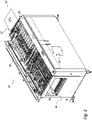
Figure 1 represents a schematic perspective view, conventionally from the front, of a sheet stacking equipment according to the invention; -
Fig. 2 shows a schematic perspective view, conventionally from the rear, of the equipment ofFig. 1 ; -
Fig. 3 represents a partial side section of the equipment ofFig. 1 ; -
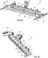
Figs. 3a and 3b show some parts ofFig. 3 , on an enlarged scale; -
Fig. 4 represents a schematic perspective view of some components of the stacking equipment ofFig. 1 ; -
Fig. 5 represents a schematic perspective view of other components of the equipment ofFig. 1 ; -
Fig. 5a shows another schematic perspective view of the components ofFig. 5 ; -
Fig. 5b shows a further schematic perspective view of the components ofFig. 5 ; -
Fig. 6 represents a schematic perspective view of other components of the equipment ofFig. 1 ; -
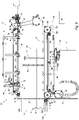
Figures 6a and 6b show some parts ofFigure 6 , on an enlarged scale; -
Figure 7 shows a schematic perspective view of parts of the equipment ofFigure 1 ; -
Figure 8 shows the parts ofFigure 3 in another operating condition; and -
Figure 9 shows the parts ofFigure 3 in a further operating condition. - With reference to
Figures 1 ,2 and3 , thereference numeral 21 designates an equipment forstacking paper sheets 22 which includes abodywork 23 and a frame with twosides input gate 27 of thebodywork 23 and a respective rear with anoutput gate 28. - The
stacking equipment 21, through thegate 27, receives thesheets 22 horizontally from an external feeding apparatus along a feed direction "F" and, after stacking, sends astack 29 of superimposed sheets, through thegate 28, to an external user apparatus for subsequent treatments. - According to a typical application, the
paper sheets 22 are fed by a cutter "CM", while thestack 29 is delivered to a conveyor belt "CB" for delivery to the user apparatus. - The
sheet stacking equipment 21 comprises analignment section 31, a stacking and deliveringsection 32, respectively on the front and on the back, anelectronic control unit 33, a push-button panel 34 and sensor elements, not shown, arranged along the internal path of the sheets. The sensor elements are functionally connected to theelectronic unit 33 for counting the sheets to be stacked and for detecting some operating conditions and anomalies. Theequipment 21 further lodges, in a lower part, avacuum pump 36 and, optionally, acompressed air generator 37 in case an external compressed air source is not available. - The
equipment 21 is controlled by the feeding apparatus "CM", and the operating controls are carried out, for example, by means of a touch screen "CD" of the cutter "CM". - The
alignment section 31 is disposed in an upper part of thebodywork 23 and has a front projecting part defining theinput gate 27 and with a horizontal receiving surface for thesheets 22. A series ofalignment rollers 38, mounted on aframe 39, operate above the receiving surface to align, according to predetermined rules, the edges of thesheets 22, and of side by side sheets. The alignedsheets 22 are then delivered, coplanar with the receiving surface, by a pair ofdelivery rollers 40 along the fed direction "F" toward the stacking and deliveringsection 32, with adequate spacing between sheet and sheet. - The
frame 39 is hinged on theside 26 of the equipment and has the possibility of opening for an easy access to the receiving surface. Thealignment section 31 is functionally of a known type and, for simplicity, the operational description thereof is omitted here. - The stacking and delivering
section 32 is constituted by a transport andstorage group 41 adjacent to thealignment section 31 and an accumulation anddelivery group 42 disposed below thegroup 41. The transport andstorage group 41 comprisesinput rollers 43 downstream of thedelivery rollers 40 andtransport belts 44 for receiving and positioning the entering sheets above thestack 29. The accumulation anddelivery group 42 includes astack support 46 for receiving the sheets in stacking and acompensation mechanism 47 for vertically moving thestack support 46. - In the transport and storage group 41 (
Figs. 3 ,3a and 3b ), theinput rollers 43 are in mutual engagement on a horizontal geometric introduction plane "IP", coplanar with the receiving surface of thealignment section 31. In particular, theinput rollers 43 are driven through belts and pulleys by anintroduction motor 48 controlled by theelectronic unit 33 to advance in the feed direction "F" thesheets 22 emerging from thedelivery rollers 40. - The
transport belts 44 are of the flat type, of an extended shape and present respective lowerhorizontal branches 49, positioned in parallel above thestack support 46 and which define with their outer surface a transport surface "TS". Thebelts 44 are motorized for dragging the entering sheets with thelower branches 49 and depositing the sheets on thestack support 46 or on a last sheet of thestack 29 being formed, as will be described below. - According to the invention, the
sheet stacking equipment 21 comprises in the transport and storage group 41 afunctional block 50 which includes anarrest member 51 for the enteringsheets 22, apressing member 52 for thestack 29 being formed, arranged upstream of the arrest member, and asensing device 53 for the last sheet of the stack. - In particular, the functional block 50 (
Figs. 1 ,3 and5 ) comprises atransversal support plate 54, substantially vertical, on which thearrest member 51, thepressing member 52 and thesensing device 53 are transversally mounted. Theplate 54 is provided at the sides with twoslides equipment 21. In this way, thearrest member 51 can be positioned according to the length of thesheets 22 to be stacked at a convenient distance from theinput rollers 43, greater than the length of thesheets 22. - The
arrest member 51 defines a vertical alignment plane "AP" of thestack 29 and it is designated for arresting the movingsheets 22 to be stacked. During the stacking process, thesheets 22 advance by the combined action of theinput rollers 43 and thetransport belts 44. Thesheets 22, however, leave therollers 43 before their leading edges come into contact with thearrest member 51, while the shifting of the sheets before the arrest is ensured only by thetransport belts 44. - The
pressing member 52 operates on the last sheet of thestack 29 with stabilizing function. In turn, thesensing device 53 is interlocked with thecompensation mechanism 47 to ensure optimal conditions for stacking regardless of the number of stacked sheets. This, for example and in a conventional manner, by maintaining constant the height, indicated "H", between the introduction plane "IP" and the last sheet of thestack 29 or between the introduction plane "IP" and the surface of thestack support 46 in absence of sheets. - The
input rollers 43 comprise in particular adriving roller 56 and acontrast roller 57, which are arranged in a tangential condition above and below the plane "IP". Thetransport belts 44 are stretched between the drivingroller 56, arear roller 58,upper deflection rollers front deflection roller 61. - The
deflection rollers transport belts 44, while thedeflection roller 61 and therear roller 58 form thelower branches 49 with the transport surface "TS". Thebranches 63 and thebranches 49 are spaced apart so as to house mechanisms of the transport andstorage group 41 including the pressingmember 52 and thearrest member 51. In detail, with respect to the feed direction "F", thedeflection rollers roller 56, while thedeflection roller 60 is arranged upstream of therear roller 58 and downstream of thearrest member 51. - In operating conditions, the
lower branches 49 of thetransport belts 44 are arranged at a distance in height from the plane "IP" lower than the height "H", so as to leave a space "G" between the transport surface "TS" of thebranches 49 and thestack support 46 or between the transport surface "TS" and the last sheet of thestack 29. The space "G" is, for example, included between 0.2 and 0.8mm, such as to allow an easy passage of thesheets 22 to be stacked. As above reported, in the accumulation anddelivery assembly 42, thecompensation mechanism 47 regulates the height of thesupport 46 between a series of operating positions in which the height "H" is kept substantially constant. Consequently, also the space "G" between the transport surface "TS" and the last sheet of thestack 29 or the surface of the stack support, in absence of sheets is maintained constant. - The driving roller 56 (see
Figs. 4 and 5 ) defines, in a transversal direction, engagement seats for thetransport belts 44, which are alternated with support seats for drivingrings 64 of friction dragging for thesheets 22, and in which the engagement seats are for example made of elastomeric material. Thecontrast roller 57 is also made of elastomeric material. - The driving
roller 56 is driven in rotation trough pulleys and belts by theintroduction motor 48 for a dragging speed of thetransport belts 44 slightly higher than the feeding speed of thesheets 22 emerging from thedelivery rollers 40. - The
lower deflection roller 61 constitutes an insertion roller for the enteringsheets 22 and defines in a transversal direction guide seats for thetransport belts 44 alternated with support seats forelastomeric rings 67 of friction dragging for thesheets 22. Thedeflection roller 61 determinesbelt portions 68 of thetransport belts 44 included between the drivingroller 56 and theroller 61 itself, inclined downwards, for guiding the leading edges of thesheets 22 emerging from theinput rollers 43. Flexible detachment lugs 69 are interposed between thebelt portions 68 and the end portions, in slight interference with the path of thesheets 22, for facilitating the separation of the trailing edges of thesheets 22, jointly with the leaving of the sheets from theinput rollers 43. - In the
functional block 50, the pressing member 52 (Figs. 3 ,5 and5b ) comprises apressing crossbar 71 on which apneumatic actuator 72 operates. Thecrossbar 71 is contiguous to thearrest member 51 and extends in cross-section upstream of themember 51. Thecrossbar 71 is slidably mounted vertically on thesupport plate 54 and has a front slanted edge and alower surface 73 for contrasting thestack 29 and withlongitudinal notches 74 for guiding thetransport belts 44. Thenotches 74 have a depth slightly less than the thickness of thebelts 44, so as to make a section of the belts protrude from thesurface 73. - The
pressing crossbar 71 therefore presses on the portion of thestack 29 being formed contiguous to the plane "AP", in a pressure area adjacent to the leading edge of the sheets. This occurs through the sections of thetransport belts 44 projecting from thelongitudinal notches 74 and, in a direct manner, through thelower surface 73 of thecrossbar 71. - In detail, the
pressing crossbar 71 is connected laterally to thesupport plate 54 by means of compensation springs 76 and is slidably guided byvertical guides 75 coaxial with thesprings 76 up to end stops. At the center, thecrossbar 71 is connected to thepneumatic actuator 72 by means of a ball joint 78. - Conveniently, the action exerted by the pressing
member 52 is adjustable according to the operating conditions of theequipment 21, while thesprings 76 are adjusted so as to compensate for the weight of the movable parts. Specifically, theactuator 72 is connected to thecompressed air generator 37 by means of a pressure regulator, not shown, which can be set on the basis of one or more of the parameters relating to: the dragging speed of the sheets, the thickness, the weight and the finishing of the sheets used, and the current height of the stack being formed. This in response of an algorithm performed by theelectronic control unit 33, on the basis on experimental data under various conditions of use. - As an alternative, the actuator for the
pressing crossbar 71 may be of an electromechanical type with the possibility of varying the operating pressure and manually setting said operating pressure on the basis of other considerations. - The
sheet stacking equipment 21 may optionally be configured to form thestack 29 with overlapping sheets ofregular blocks 79r and staggered blocks 79o. Theregular blocks 79r are aligned according to the alignment plane "AP", while the staggered blocks 79o are aligned on a plane "OP" which is offset at the front with respect to the plane "AP". To this end, the transport andstorage group 41 comprises an offsetarrest member 81, which is also mounted on thefunctional block 50, upstream of thearrest member 51, and which can be actuated as an alternative to the actuation of themember 51. - The
arrest member 51 is formed by across bar 80 with a plurality of arrest lugs 82 (see FIG.Fig. 5a ) in a lower part, fixed behind thesupport plate 54. The arrest lugs 82 are aligned transversally and project from thelower branches 49 of thetransport belts 44 to define the alignment plane "AP" of thestack 29. - The offset
arrest member 81 comprises avertical plate 85 with a plurality of offsetlugs 83 projecting downwardly and also aligned transversally. Theplate 85 is slidably mounted behind theplate 54 between thebar 80 and theplate 54 and is vertically shiftable by means of apneumatic actuator 84 from a high, inactive position to a lowered, operative position. In the lowered position, the offset lugs 83 project from thelower branches 49 and define the offset alignment plane "OP" for the blocks 79o of thestack 29. - Conveniently, the
crossbar 71 of the pressingmember 52 defines a row oftransversal notches 86 and a row oftransversal windows 87. The arrest lugs 82 are freely housed in thetransversal notches 86, while the offset lugs 83 are slidably guided by thetransversal windows 87. - The
sensing device 53 can be of any type and detects the height of thestack 29 by sensing the position of the pressingmember 52 so as to minimize possible errors due to wrinkles and deformations of the last sheet of the stack. In a preferred embodiment, thedevice 53 comprises a laser illuminator/detector 88 mounted through a bracket (not shown) on thesupport plate 54 and atarget area 89 formed on an upper surface of thepressing crossbar 71. - The
transport belts 44 haveholes 91 distributed regularly along a longitudinal axis, while the transport andstorage group 41 comprises one ormore ducts 92 arranged transversally above thelower branches 49 of thebelts 44. Theducts 92 each define, in alower surface 93, longitudinal notches 94 (see FIG.Fig. 5b ) for guiding thebelts 44. - The duct or
ducts 92 are connected, via flexible hoses and a manifold 95, to thevacuum pump 36 and havesuction openings 96 at theguide notches 94. This is to cause a suction action on thesheets 22 through theholes 91 of thetransport belts 44 with dragging by adherence of the enteringsheets 22 by thebelts 44 up to their arrest against thelugs - In the herein represented embodiment, the
equipment 21 is designated for stacking sheets of considerable longitudinal extension and includes three ducts 92-1, 92-2 and 92-3: the duct 92-1 is arranged downstream of thedeflection roller 61, the duct 92-3 is arranged upstream and at short distance from the pressingmember 52, while the duct 92-2 is in an intermediate position between the ducts 92-1 and 92-3. It is also clear that theequipment 21 can provide a greater or lesser number ofducts 92 or a single duct depending on the lengths of the sheets to be stacked. - Conveniently, the duct or
ducts 92 are mounted on slides which can slide along the lateral guides 56r and 56i and can also be positioned at different distances from theinput rollers 43 depending on the length of thesheets 22. - For effective jamming-free shifting, the
sheets 22 must adhere to thetransport belts 44 sufficiently for dragging, but must be able to be easily detached at the time of stacking. Moreover, before the detachment and when the sheets have been arrested by thelugs belts 44 is therefore an important parameter for a reliable stacking of thesheets 22. - The problems of wrinkles or other deformations of the sheets and jamming are serious if the
equipment 21 should handle sheets of very different characteristics as for weight, rigidity and smoothness, variable for example from a tissue paper to a coated paper. The use of transport belts with a friction coefficient selected for reference papers of a given type may cause drawbacks when theequipment 21 handles sheets of types very different from those of the reference papers. - Advantageously, it has been found that the above problems are solved by using together transport belts for the sheet having different friction coefficients.
- According to a feature of the invention, the stacking
equipment 21, in the transport andstorage group 41, employs 12transport belts 44, of which eight belts with a low friction coefficient (grip 0.2 on steel) are alternated with four belts with a medium friction coefficient (grip 0.4 on steel). By virtue of this solution, theequipment 21 can reliably and at high speed (250 m/mn) stacking sheets of paper with a weight of 40 to 300 g/m2 and finishes including coating. - In the accumulation and
delivery group 42, the stack support 46 (Figs. 3 ,3b and7 ) comprises aframe 97 of rectangular outline, a pair oftransversal shafts rings 101 of theshaft 99 and adelivery motor 102. - The
frame 97 extends below the transport andstorage group 41 and rotatably supports theshafts - The support and
delivery blocks 100 have a longitudinally extended parallelepiped shape, and are carried side by side by theframe 97 transversally spaced from one another by the driving rings 101. Thedelivery motor 102 is mounted on a lower part of theframe 97 and drives thetransversal shaft 99 through respective pulleys and belts. - The support and
delivery blocks 100 each comprise aspar 103, a pair ofpulleys shafts sides spar 103 and thepulleys 104, anextended delivery belt 107 with upper and lower branches stretched between thepulleys belt 107. - The
pulleys block 100 and the driving rings 101 present upper sectors in a condition of tangency with an upper surface of thelongitudinal members 103. Thepulleys 104 and thedelivery belts 107 are toothed for a positive driving by themotor 102. The upper branches of thebelts 107 rest with internal teeth on a upper surface of thespar 103, while the lower branches are deflected upwards by the rollers 108-1, 108-2 and 108-3. - The set of the upper branches of the
delivery belts 107 defines a bearing surface "BS" for thestack 29 being formed, with contrast on the part of thespars 103. Thedelivery belts 107 are driven by themotor 102 in the direction "F", with sliding of the internal teeth on the upper surfaces of the spars in some operating conditions of theequipment 21. - The
stack support 46 has the possibility of vertical displacement by means ofvertical guides 109 between a reference position "RP" (Figure 3 ) and a delivery position "DP" (Figure 9 ). The reference position "RP" is the highest of thestack support 46, for a sheet-free condition in which the bearing surface "BS" of thedelivery belts 104 is spaced by the space "G" from the conveying surface "TS". The delivery position "DP" is the lowest of thestack support 46 and wherein the surface "BS" is substantially coplanar with a lower edge of theoutput gate 28 and with the conveyor belt "CB". - Conveniently, a
panel 110 is mounted vertically downward on a rear portion of theframe 97. Theoutput gate 28 is shielded by thepanel 110 when thestack support 46 is in the reference position "RP" and is free for the passage of the stack when thesupport 46 is in the delivery position "DP". - As above reported, depending on the number of accumulated sheets, the
compensation mechanism 47 lowers thestack support 46 below the reference position "RP" to keep the space "G" constant. Themechanism 47 also moves the stack support between the position reached upon completion of thestack 29 and the delivery position "DP". In this "DP" position, thebelts 107 are moved by thedelivery motor 102 to forward thestack 29, through theoutput gate 28 toward the conveyor belt "CB" for the subsequent treatments. - The
compensation mechanism 47 comprises a pair of ball screws withgrooved shafts frame 97, while thegrooved shafts transversal plate 116 and are driven in rotation, throughf belts and pulleys by acompensation motor 117 also controlled by theelectronic unit 33. - The operation of the
sheet stacking equipment 21 is as follows:
Depending on the longitudinal dimensions of thesheets 22 to be stacked, the operator positions thefunctional block 50 and the duct orducts 92 at programmed distances from theinput rollers 43. By means of the touch screen "CD" (Figure 1 ), data are also set on the number ofsheets 22 to be stacked, the number of sheets of blocks to be staggered in the case of offset stacking, and on the characteristics of the sheet. With these settings, theelectronic unit 33 also regulates the pressure in theactuator 72 to optimize the operating parameters. - In an initial stage of stacking, the stack support 46 (
Figure 3 ) is empty and in the reference position "RP", height "H" from the plane "IP" and distance "G" between the bearing surface "BS" and the conveying surface "TS" of thebranches 49 of thetransport belts 44. The arrest lugs 82 are interposed in the spaces between the support anddelivery blocks 100 and thecrossbar 71 of the pressingmember 52 presses on thedelivery belts 107 at the pressure determined by theelectronic unit 33. Theoutput gate 28 is shielded by thepanel 110. - Upon receipt of the
first sheet 22 from thedelivery rollers 40, theelectronic unit 33 activates theintroduction motor 48, rotating theinput rollers 43 with movement of thetransport belts 44 at a driving speed slightly higher than the feeding speed of thesheets 22. Moreover, limited to this first sheet, theunit 33 also activates thedelivery motor 105, moving the upper branches of thedelivery belts 107 in the feed direction "F" with a speed slightly higher than the speed of thesheets 22 emerging from theinput rollers 43. - At the exit from the
alignment section 31, theinput rollers 43 advance the sheet on the introduction plane "IP" in the direction "F" and along theinclined belt portions 68. The sheet is flexed and accompanied downwards until its leading edge meets thedelivery belts 107 which are in movement. This due to the positive thrust action by therollers 43, also facilitated by the driving rings 64, theinclined portions 68 and thedeflection roller 61 with the driving rings 67. - After the contact with the
delivery belts 107, the sheet is flexed and accompanied horizontally again by the action of theinput rollers 43 and with the contribution of thedeflection roller 61, thebranches 49 of thetransport belts 44 and now also by the upper branches of thebelts 107. - The
first sheet 22 continues its travel by resting on thedelivery belts 107, until its leading edge surpasses the position of the duct 92-1. Here, the sheet is lifted against thelower branches 49 of thetransport belts 44. This owing to the suction action of the conduit 92-1 through theopenings 96 of theguide notches 94 and through theholes 91 of thebelts 44. Thesheet 22 continues to advance with passage and suction of successive parts of the sheet at theopenings 96, through followingholes 91 of thebelts 44, by the combined positive driving action of theinput rollers 43 and owing to the friction dragging of the upper branches, in motion, of thedelivery belts 107. - In the case where the
equipment 21 also includes the ducts 92-2 and 92-3, after the lifting of thesheet 22 by the duct 92-1, the adhesion to thetransport belts 44 is improved by the suction of the ducts 92-2 and 92-3, when the sheet passes in front of these ducts 92-2 and 92-3. - After leaving the trailing edge of the sheet from the
input rollers 43, thesheet 22 continues to be dragged by friction by thesole transport belts 44 ensured by the suction action of the duct orducts 92 and causing the sheet to enter completely into the transport andstorage group 41. The sheet now tends to resume a flat configuration and to rest with the trailing edge on thedelivery belts 107, facilitated by the detachment lugs 69. - Continuing its friction movement by the
transport belts 44, thefirst sheet 22 meets with its leading edge the pressingmember 52, with downward deviation caused by the slanted edge of thepressing crossbar 71. Through thebelts 44 and thesurface 73 of thecrossbar 71, theactuator 72 further pushes thesheet 22 against thedelivery belts 107 with the set pressure. The sheet is finally arrested when it meets thelugs 82 of thearrest member 51, with thebelts 44 sliding in motion with respect to the sheet. Theelectronic unit 33 arrests thedelivery motor 102 and consequently thebelts 107 but keeps theintroduction motor 48 activated and therefore theinput rollers 43, the drivingroller 56 and thebelts 44 in motion, waiting for a followingsheet 22 for stacking. - The complete introduction of the
first sheet 22 into the transport andstorage group 41, on command of theelectronic unit 33, causes thecompensation motor 117 to be actuated, rotating thegrooved shafts stack support 46 by an amount corresponding to the thickness of the sheet. This in response to feedback information from the laser illuminator/detector 88 on the position of thepressing crossbar 71 as detected in thetarget area 89. In this way, the space "G" intended for the passage of a new sheet to be stacked is kept constant at its optimum value. - A
new sheet 22 entering theinput rollers 43 is also flexed and accompanied downwards by the drivingroller 56 and theinclined belt portions 68, but its leading edge now meets the preceding sheet. Due to the thrust action of theinput rollers 43 and the facilitation of theroller 56 with therings 64, theinclined portions 68 and theinsertion roller 61 with therings 67, the new sheet is flexed and accompanied horizontally and inserting itself between thelower branches 49 of thetransport belts 44 and the parts of a preceding sheet still adhering to thebranches 49. - The
new sheet 22 continues its travel above the preceding sheet, until its leading edge reaches the duct 92-1, putting itself in contact with thelower surface 93. The part of the preceding sheet, no longer retained by the suction of the duct 92-1 falls on the surface "BS" of thesupport 46, while the new sheet adheres to thelower branches 49 of thetransport belts 44 and is dragged by it. The new sheet then continues to advance for the passage and suction of successive parts in front of the duct 92-1 and the ducts 92-2 and 92-3, while the preceding sheet progressively rests on the upper branches of thedelivery belts 107, as the first sheet of thestack 29. - The
new sheet 22 also continues its movement by thetransport belts 44 alone for the adhesion ensured by the duct orducts 92 after the leaving of its trailing edge from theinput rollers 43. The new sheet tends to resume a flat configuration and to rest with the trailing edge on the preceding sheet, facilitated by the detachment lugs 69. In sequence, thenew sheet 22 is deflected downwards by thepressing crossbar 71 of the pressingmember 52 and pressed against the underlying sheet by theactuator 72. The sheet is finally stopped when its leading edge contacts the arrest lugs 82, with sliding of the sheet with thetransport belts 44 in motion. - Full introduction of the
new sheet 22 into the transport andstorage group 41 causes thecompensation motor 117 to start again upon control of theelectronic unit 33 and feedback by thesensing device 53 and further loweringof thestack support 46 by the amount corresponding to the thickness of the sheet so as to keep the space "G" constant. - The following sheets are stacked sequentially as described above for the second sheet, with progressive formation of the
stack 29. - If the offset option is provided, after the setting of the number of sheets constituting each
regular block 79r has been stacked, theelectronic unit 33 activates the offsetactuator 84. The offset lugs 83 are lowered through thewindows 87 of thepressing crossbar 71 placing the ends below thelower branches 49, whereby determining the offset alignment plane "OP" for the staggered blocks 79o. - During stacking, the pressing
member 52 exerts its action on a pressure area of the sheets adjacent to the pressing member. This prevents the impact of an entering sheet against the arrest lugs 82 or against the offset lugs 83 and the thrust of thetransport belts 44 from causing the leading edge to be lifted and the sheet to curl, resulting in overlapping and jamming upon arrival of the subsequent sheets. In turn, the detection of the position of the sheet previously stacked by means of thetarget area 89 of thepressing crossbar 71, as information for maintaining the best height "H", prevents wrinkles or deformations on the stacked sheet from giving rise to errors in the position of thesupport 46 and space values "G" different from the optimal one, with other risks of jams for the new sheet to be stacked. - Upon reaching the number of
sheets 22 or the number ofblocks 79r and 79o to be stacked, theelectronic unit 33 again activates thecompensation motor 117, moving thestack support 46 from the last stacking position to the delivery position "DP", without any servo to thesensing device 53. The bearing surface "BS" of the delivery belts 107 (Fig. 8 ) is now coplanar with the conveyor belt "CB" and thepanel 110 is below theoutput gate 28, completely discovering it. - The
electronic unit 33 now activates thedelivery motor 102, moving the upper branches of thedelivery belts 107 in the "F" direction, and consequently dragging thestack 29 with the sheets stacked on the conveyor belt "CB" for delivery to the user equipment. - Upon completion of the delivery of the
stack 29, theelectronic unit 33 arrests themotor 102 and activates thecompensation motor 117, with rotation of thesplined shafts stack support 46 up to the reference position "RP" ofFigure 3 for the start of a new stacking. - Naturally, the principle of the invention remaining the same, the embodiments and details of construction of the equipment for stacking sheets may be widely varied with respect to what has been described and illustrated by way of non-limiting example, without by this departing from the ambit of the present invention.
Claims (15)
- An equipment for stacking sheets comprising a stack support for sheets in vertical stacking, input rollers for introducing and feeding sheets along a given direction, a plurality of elongated transport belts with lower branches arranged above the stack support and a compensation mechanism for modifying the height of the stack support with respect to a reference surface and wherein the transport belts are motorized for shifting entering sheets with the lower branches and depositing the sheets on the stack support or on stacked sheets, the said equipment being characterized in that it comprisesan arrest member for the entering sheets, a pressing member for a forming stack, a sensor device for the height of a last sheet of the stack and an electronic control unit, whereinthe arrest member is designated for arresting and aligning sheets in stacking against a stack alignment surface;the pressing member is contiguous to the arrest member and operates on the last sheet of the stack on a pressing area adjacent to a leading edge of said last sheet of the stack with stabilization function; whereinthe pressing member comprises a pressing cross member having a lower surface of contrast for the stack, said cross member operates on the pressing area of the last sheet of the stack with its lower surface and whereinthe compensation mechanism is servoized to the sensor device, on control by the electronic unit, for maintaining constant the height of the last sheet of the stack from the reference surface.
- Equipment according to claim 1 characterized in that said sensor device is functional to the height of the pressing cross member with respect to the reference surface includes an illuminator / detector laser and wherein the pressing cross member defines a target area for said illuminator / detector laser.
- Equipment for stacking sheets according to claim 1 or 2 characterized in that the input rollers comprise a driving roller, while the transport belts are extended between the driving roller, a rear roller and deflection rollers, and in which said deflection rollers include an insertion roller for the lower branches of the belts, the entering sheets emerging from the input rollers are deviated towards the stack support by inclined sections of the belts included between the driving roller and the insertion roller and wherein flexible detachment lugs interposed between the inclined belt sections are provided for facilitating the detachment of the entering sheets from the transport belts, jointly with the leaving of the sheets from the input rollers.
- Equipment for stacking sheets according to claim 1 or 2 or 3 characterized in that the lower surface of the pressing cross member defines longitudinal notches of guide for the transport belts and wherein the lower surface of said cross member further operates on the pressing area of the last sheet of the stack through sections of the said belts guided by the longitudinal notches.
- Equipment for stacking sheets according to one of the preceding claims, also comprising an actuator for the operation of said pressing cross member, said cross member is slidably mounted on a support structure and is connected to the support structure by means of springs of compensation for its weight, and wherein said actuator can be adjusted for modifying its action on the pressing cross member.
- Equipment for stacking sheets according to one of the preceding claims, wherein the pressing member is operated by a pneumatic actuator and wherein the electronic control unit determines the operating pressure of the said actuator on the basis of one or more of the following parameters: sheet shifting speed, thickness, weight and finish of used sheets, and current height of the stack in formation.
- Equipment for stacking sheets according to one of the preceding claims, wherein it further comprises an offset arrest member as an alternative to the arrest member for arresting the entering sheets against an offset surface of the stack, which is offset with respect to said stack alignment surface, the arrest member and the offset arrest member are formed by a plurality of arrest lugs and by a plurality of transversal offset lugs and wherein the pressing member comprises a pressing crossbar with a lower surface for contrasting the stack and housing windows for the arrest lugs and the offset lugs.
- Equipment for stacking sheets according to one of the preceding claims, wherein it comprises a functional block which includes a mounting support for the arrest member, the pressing member and the sensor device and wherein said mounting support is longitudinally shiftable so as to position the arrest member at a distance from the input rollers depending on the length of the sheets to be stacked, greater than said length.
- Equipment for stacking sheets according to one of the preceding claims, wherein said equipment further comprises one or more ducts arranged transversely above the lower branches of the transport belts and with guiding areas for said branches, the transport belts have longitudinal holes, and wherein the duct or ducts are connected to a vacuum source and have openings in correspondence with the guiding areas for a suction action, trough said holes, on the entering sheets with dragging due to adhesion of the entering sheets by the transport belts.
- Equipment for stacking sheets according to one of the preceding claims, wherein the transport belts comprise a group of belts having a low coefficient of friction and a second group of belts having a medium coefficient of friction.
- Equipment for stacking sheets according to one of the preceding claims, wherein the stack support comprises a plurality of elongated delivery belts and support members for said delivery belts, said stack support is operatively connected with the compensation mechanism, while the elongated delivery belts have respective upper branches which are guided by the stack support, wherein said stack support can be vertically moved to a delivery position, the transport belts are longitudinally driven by a delivery motor and wherein said delivery motor is operable for forwarding the stacked sheets to following treatments in the delivery position of the stack support.
- An equipment for high-speed stacking of paper sheets comprising a stack support for sheets in vertical stacking, input rollers for introducing and advancing the sheets, and a plurality of transport belts of elongated shape with lower branches arranged above the stack support, wherein the transport belts are motorized for shifting entering sheets with the lower branches along a feeding direction and depositing said sheets on the stack support or on stacked sheets, the said equipment being characterized in that it further comprisesone or more ducts arranged transversely above the lower branches of the transport belts, said duct or ducts being connected to a vacuum source and having guiding areas for said branches,an arrest member arranged downstream of the duct or ducts for arresting the entering sheets and sheets in stacking; anda compensation mechanism for maintaining constant the height of a last sheet of the stack from the lower branches of the transport belts, whereinthe transport belts have longitudinal holes, while the duct or ducts have openings in correspondence with the guiding areas for a suction action on the entering sheets through said holes with dragging due to adhesion and friction of the entering sheets by the transport belts; and whereinthe said transport belts comprise a group of belts with a low coefficient of friction and another group of belts with a medium coefficient of friction.
- Equipment for stacking sheets in accordance with claim 13 characterized in that the transport belts with the low coefficient of friction have a grip of 0.2 on steel, while the belts with the medium coefficient of friction have a grip of 0.4 on steel.
- Equipment for stacking sheets according to claim 12 or 13 characterized in that it further comprises a pressing member contiguous to the arrest member which operates on the last sheet of the stack on a pressing area adjacent to a leading edge of said last sheet with stabilization function.
- Equipment for stacking sheets according to claim 14 characterized in that it comprises a functional block which includes a support on which are mounted the arrest member, the pressing member and a sensor device for the compensation mechanism and wherein said support is longitudinally shiftable so as to position the arrest member at a distance from the input rollers depending on the length of the sheets to be stacked, greater than the said length of the sheets.
Applications Claiming Priority (1)
| Application Number | Priority Date | Filing Date | Title |
|---|---|---|---|
| IT102021000016211A IT202100016211A1 (en) | 2021-06-21 | 2021-06-21 | SHEET STACKING EQUIPMENT |
Publications (2)
| Publication Number | Publication Date |
|---|---|
| EP4108616A1 true EP4108616A1 (en) | 2022-12-28 |
| EP4108616B1 EP4108616B1 (en) | 2024-12-04 |
Family
ID=77711310
Family Applications (1)
| Application Number | Title | Priority Date | Filing Date |
|---|---|---|---|
| EP22179951.3A Active EP4108616B1 (en) | 2021-06-21 | 2022-06-20 | Sheet stacking equipment |
Country Status (3)
| Country | Link |
|---|---|
| US (1) | US12503330B2 (en) |
| EP (1) | EP4108616B1 (en) |
| IT (1) | IT202100016211A1 (en) |
Citations (7)
| Publication number | Priority date | Publication date | Assignee | Title |
|---|---|---|---|---|
| US4470591A (en) * | 1982-08-12 | 1984-09-11 | Xerox Corporation | Variable force document handling system |
| US5076754A (en) * | 1989-07-20 | 1991-12-31 | Windmoller & Holscher | Apparatus for forming stacks from consecutively conveyed, flat workpieces |
| US5671920A (en) * | 1995-06-01 | 1997-09-30 | Xerox Corporation | High speed printed sheet stacking and registration system |
| JP2008266020A (en) * | 2007-03-23 | 2008-11-06 | Fujifilm Corp | Sheet material accumulating apparatus and sheet material accumulating method |
| US8066282B2 (en) * | 2008-07-11 | 2011-11-29 | Heidelberger Druckmaschinen Ag | Apparatus for feeding and aligning sheets fed to a processing machine, in particular a printing machine |
| US8141869B2 (en) | 2007-08-20 | 2012-03-27 | Lasermax Roll Systems Ab | Arrangement for stacking sheets |
| EP2623005A1 (en) * | 2010-09-30 | 2013-08-07 | Unicharm Corporation | Device for producing and method for producing wet wipes |
Family Cites Families (4)
| Publication number | Priority date | Publication date | Assignee | Title |
|---|---|---|---|---|
| US7628396B2 (en) * | 2007-03-21 | 2009-12-08 | Xerox Corporation | High speed shingled sheet compiler |
| ITMI20150653A1 (en) * | 2015-05-08 | 2016-11-08 | Elatech Srl | DRIVE BELT |
| KR101633594B1 (en) * | 2016-04-07 | 2016-06-24 | (주)한도기공 | X-axis and y-axis mobile apparatus for autpmatically stacking rubber sheet using press roller |
| US20210039905A1 (en) * | 2019-08-06 | 2021-02-11 | Shred Holdings, LLC | Document shredding machine |
-
2021
- 2021-06-21 IT IT102021000016211A patent/IT202100016211A1/en unknown
-
2022
- 2022-06-20 EP EP22179951.3A patent/EP4108616B1/en active Active
- 2022-06-21 US US17/844,840 patent/US12503330B2/en active Active
Patent Citations (7)
| Publication number | Priority date | Publication date | Assignee | Title |
|---|---|---|---|---|
| US4470591A (en) * | 1982-08-12 | 1984-09-11 | Xerox Corporation | Variable force document handling system |
| US5076754A (en) * | 1989-07-20 | 1991-12-31 | Windmoller & Holscher | Apparatus for forming stacks from consecutively conveyed, flat workpieces |
| US5671920A (en) * | 1995-06-01 | 1997-09-30 | Xerox Corporation | High speed printed sheet stacking and registration system |
| JP2008266020A (en) * | 2007-03-23 | 2008-11-06 | Fujifilm Corp | Sheet material accumulating apparatus and sheet material accumulating method |
| US8141869B2 (en) | 2007-08-20 | 2012-03-27 | Lasermax Roll Systems Ab | Arrangement for stacking sheets |
| US8066282B2 (en) * | 2008-07-11 | 2011-11-29 | Heidelberger Druckmaschinen Ag | Apparatus for feeding and aligning sheets fed to a processing machine, in particular a printing machine |
| EP2623005A1 (en) * | 2010-09-30 | 2013-08-07 | Unicharm Corporation | Device for producing and method for producing wet wipes |
Also Published As
| Publication number | Publication date |
|---|---|
| US12503330B2 (en) | 2025-12-23 |
| EP4108616B1 (en) | 2024-12-04 |
| US20220402720A1 (en) | 2022-12-22 |
| IT202100016211A1 (en) | 2022-12-21 |
Similar Documents
| Publication | Publication Date | Title |
|---|---|---|
| US4192496A (en) | Apparatus for feeding case blank sheets | |
| US5004220A (en) | Method and apparatus for changing the direction of sheet conveyance | |
| US5279536A (en) | Handling apparatus for a continuous web of Z-fold computer paper | |
| EP2919206B1 (en) | Sheet-type medium stacking device | |
| US7717418B2 (en) | Envelope conveying and positioning apparatus and related methods | |
| EP0115208B1 (en) | Card feeder control | |
| US5499806A (en) | Collating machine | |
| US4890825A (en) | Paper sheet stacking and jogging apparatus | |
| EP0305570B1 (en) | Apparatus for preventing disorder in sheet alignment | |
| US6142288A (en) | Fanfold sheet feeder having stack positioner | |
| WO2010042779A2 (en) | System and method for rotating sheets | |
| US4010944A (en) | Blank feeding device having an adjustable and automatic positioning backstop means | |
| EP4108616A1 (en) | Sheet stacking equipment | |
| US7052009B2 (en) | Sheet deceleration apparatus and method | |
| US5851008A (en) | Paper handling apparatus | |
| JP2008169044A (en) | Apparatus and method for aligning a stack of sequentially stacked sheets | |
| US5441249A (en) | Method and device for separating lifts from a stack of sheets | |
| JPH07144778A (en) | Sheet accumulated bundle transfer method and device | |
| US20070246881A1 (en) | Device for conveying sheet-type flat items | |
| US2951575A (en) | Classifier | |
| CA2181966A1 (en) | Apparatus for delivering printed products to a further-processing location | |
| US5076558A (en) | Mechanism for facilitating document sheet settling in an improved recirculating document feeder | |
| RS54710B1 (en) | SHEET BINDING DEVICES | |
| US4465270A (en) | Apparatus for handling single sheets delivered in succession | |
| CN213864664U (en) | Pre-paper-receiving mechanism and printing production line |
Legal Events
| Date | Code | Title | Description |
|---|---|---|---|
| PUAI | Public reference made under article 153(3) epc to a published international application that has entered the european phase |
Free format text: ORIGINAL CODE: 0009012 |
|
| STAA | Information on the status of an ep patent application or granted ep patent |
Free format text: STATUS: THE APPLICATION HAS BEEN PUBLISHED |
|
| AK | Designated contracting states |
Kind code of ref document: A1 Designated state(s): AL AT BE BG CH CY CZ DE DK EE ES FI FR GB GR HR HU IE IS IT LI LT LU LV MC MK MT NL NO PL PT RO RS SE SI SK SM TR |
|
| STAA | Information on the status of an ep patent application or granted ep patent |
Free format text: STATUS: REQUEST FOR EXAMINATION WAS MADE |
|
| 17P | Request for examination filed |
Effective date: 20230619 |
|
| R17P | Request for examination filed (corrected) |
Effective date: 20230619 |
|
| RBV | Designated contracting states (corrected) |
Designated state(s): AL AT BE BG CH CY CZ DE DK EE ES FI FR GB GR HR HU IE IS IT LI LT LU LV MC MK MT NL NO PL PT RO RS SE SI SK SM TR |
|
| GRAP | Despatch of communication of intention to grant a patent |
Free format text: ORIGINAL CODE: EPIDOSNIGR1 |
|
| STAA | Information on the status of an ep patent application or granted ep patent |
Free format text: STATUS: GRANT OF PATENT IS INTENDED |
|
| INTG | Intention to grant announced |
Effective date: 20240604 |
|
| GRAS | Grant fee paid |
Free format text: ORIGINAL CODE: EPIDOSNIGR3 |
|
| GRAA | (expected) grant |
Free format text: ORIGINAL CODE: 0009210 |
|
| STAA | Information on the status of an ep patent application or granted ep patent |
Free format text: STATUS: THE PATENT HAS BEEN GRANTED |
|
| AK | Designated contracting states |
Kind code of ref document: B1 Designated state(s): AL AT BE BG CH CY CZ DE DK EE ES FI FR GB GR HR HU IE IS IT LI LT LU LV MC MK MT NL NO PL PT RO RS SE SI SK SM TR |
|
| REG | Reference to a national code |
Ref country code: CH Ref legal event code: EP |
|
| REG | Reference to a national code |
Ref country code: DE Ref legal event code: R096 Ref document number: 602022008324 Country of ref document: DE |
|
| REG | Reference to a national code |
Ref country code: IE Ref legal event code: FG4D |
|
| REG | Reference to a national code |
Ref country code: LT Ref legal event code: MG9D |
|
| REG | Reference to a national code |
Ref country code: NL Ref legal event code: MP Effective date: 20241204 |
|
| PG25 | Lapsed in a contracting state [announced via postgrant information from national office to epo] |
Ref country code: HR Free format text: LAPSE BECAUSE OF FAILURE TO SUBMIT A TRANSLATION OF THE DESCRIPTION OR TO PAY THE FEE WITHIN THE PRESCRIBED TIME-LIMIT Effective date: 20241204 |
|
| PG25 | Lapsed in a contracting state [announced via postgrant information from national office to epo] |
Ref country code: FI Free format text: LAPSE BECAUSE OF FAILURE TO SUBMIT A TRANSLATION OF THE DESCRIPTION OR TO PAY THE FEE WITHIN THE PRESCRIBED TIME-LIMIT Effective date: 20241204 |
|
| PG25 | Lapsed in a contracting state [announced via postgrant information from national office to epo] |
Ref country code: BG Free format text: LAPSE BECAUSE OF FAILURE TO SUBMIT A TRANSLATION OF THE DESCRIPTION OR TO PAY THE FEE WITHIN THE PRESCRIBED TIME-LIMIT Effective date: 20241204 |
|
| PG25 | Lapsed in a contracting state [announced via postgrant information from national office to epo] |
Ref country code: ES Free format text: LAPSE BECAUSE OF FAILURE TO SUBMIT A TRANSLATION OF THE DESCRIPTION OR TO PAY THE FEE WITHIN THE PRESCRIBED TIME-LIMIT Effective date: 20241204 |
|
| PG25 | Lapsed in a contracting state [announced via postgrant information from national office to epo] |
Ref country code: NO Free format text: LAPSE BECAUSE OF FAILURE TO SUBMIT A TRANSLATION OF THE DESCRIPTION OR TO PAY THE FEE WITHIN THE PRESCRIBED TIME-LIMIT Effective date: 20250304 |
|
| PG25 | Lapsed in a contracting state [announced via postgrant information from national office to epo] |
Ref country code: LV Free format text: LAPSE BECAUSE OF FAILURE TO SUBMIT A TRANSLATION OF THE DESCRIPTION OR TO PAY THE FEE WITHIN THE PRESCRIBED TIME-LIMIT Effective date: 20241204 Ref country code: GR Free format text: LAPSE BECAUSE OF FAILURE TO SUBMIT A TRANSLATION OF THE DESCRIPTION OR TO PAY THE FEE WITHIN THE PRESCRIBED TIME-LIMIT Effective date: 20250305 |
|
| PG25 | Lapsed in a contracting state [announced via postgrant information from national office to epo] |
Ref country code: RS Free format text: LAPSE BECAUSE OF FAILURE TO SUBMIT A TRANSLATION OF THE DESCRIPTION OR TO PAY THE FEE WITHIN THE PRESCRIBED TIME-LIMIT Effective date: 20250304 |
|
| PG25 | Lapsed in a contracting state [announced via postgrant information from national office to epo] |
Ref country code: NL Free format text: LAPSE BECAUSE OF FAILURE TO SUBMIT A TRANSLATION OF THE DESCRIPTION OR TO PAY THE FEE WITHIN THE PRESCRIBED TIME-LIMIT Effective date: 20241204 |
|
| REG | Reference to a national code |
Ref country code: AT Ref legal event code: MK05 Ref document number: 1747988 Country of ref document: AT Kind code of ref document: T Effective date: 20241204 |
|
| PG25 | Lapsed in a contracting state [announced via postgrant information from national office to epo] |
Ref country code: SM Free format text: LAPSE BECAUSE OF FAILURE TO SUBMIT A TRANSLATION OF THE DESCRIPTION OR TO PAY THE FEE WITHIN THE PRESCRIBED TIME-LIMIT Effective date: 20241204 |
|
| PG25 | Lapsed in a contracting state [announced via postgrant information from national office to epo] |
Ref country code: PL Free format text: LAPSE BECAUSE OF FAILURE TO SUBMIT A TRANSLATION OF THE DESCRIPTION OR TO PAY THE FEE WITHIN THE PRESCRIBED TIME-LIMIT Effective date: 20241204 |
|
| PGFP | Annual fee paid to national office [announced via postgrant information from national office to epo] |
Ref country code: DE Payment date: 20250627 Year of fee payment: 4 |
|
| PG25 | Lapsed in a contracting state [announced via postgrant information from national office to epo] |
Ref country code: IS Free format text: LAPSE BECAUSE OF FAILURE TO SUBMIT A TRANSLATION OF THE DESCRIPTION OR TO PAY THE FEE WITHIN THE PRESCRIBED TIME-LIMIT Effective date: 20250404 |
|
| PG25 | Lapsed in a contracting state [announced via postgrant information from national office to epo] |
Ref country code: PT Free format text: LAPSE BECAUSE OF FAILURE TO SUBMIT A TRANSLATION OF THE DESCRIPTION OR TO PAY THE FEE WITHIN THE PRESCRIBED TIME-LIMIT Effective date: 20250404 |
|
| PG25 | Lapsed in a contracting state [announced via postgrant information from national office to epo] |
Ref country code: EE Free format text: LAPSE BECAUSE OF FAILURE TO SUBMIT A TRANSLATION OF THE DESCRIPTION OR TO PAY THE FEE WITHIN THE PRESCRIBED TIME-LIMIT Effective date: 20241204 |
|
| PGFP | Annual fee paid to national office [announced via postgrant information from national office to epo] |
Ref country code: FR Payment date: 20250625 Year of fee payment: 4 |
|
| PG25 | Lapsed in a contracting state [announced via postgrant information from national office to epo] |
Ref country code: AT Free format text: LAPSE BECAUSE OF FAILURE TO SUBMIT A TRANSLATION OF THE DESCRIPTION OR TO PAY THE FEE WITHIN THE PRESCRIBED TIME-LIMIT Effective date: 20241204 Ref country code: RO Free format text: LAPSE BECAUSE OF FAILURE TO SUBMIT A TRANSLATION OF THE DESCRIPTION OR TO PAY THE FEE WITHIN THE PRESCRIBED TIME-LIMIT Effective date: 20241204 |
|
| PG25 | Lapsed in a contracting state [announced via postgrant information from national office to epo] |
Ref country code: SK Free format text: LAPSE BECAUSE OF FAILURE TO SUBMIT A TRANSLATION OF THE DESCRIPTION OR TO PAY THE FEE WITHIN THE PRESCRIBED TIME-LIMIT Effective date: 20241204 |
|
| PG25 | Lapsed in a contracting state [announced via postgrant information from national office to epo] |
Ref country code: CZ Free format text: LAPSE BECAUSE OF FAILURE TO SUBMIT A TRANSLATION OF THE DESCRIPTION OR TO PAY THE FEE WITHIN THE PRESCRIBED TIME-LIMIT Effective date: 20241204 |
|
| PG25 | Lapsed in a contracting state [announced via postgrant information from national office to epo] |
Ref country code: IT Free format text: LAPSE BECAUSE OF FAILURE TO SUBMIT A TRANSLATION OF THE DESCRIPTION OR TO PAY THE FEE WITHIN THE PRESCRIBED TIME-LIMIT Effective date: 20241204 |
|
| REG | Reference to a national code |
Ref country code: DE Ref legal event code: R097 Ref document number: 602022008324 Country of ref document: DE |
|
| PG25 | Lapsed in a contracting state [announced via postgrant information from national office to epo] |
Ref country code: SE Free format text: LAPSE BECAUSE OF FAILURE TO SUBMIT A TRANSLATION OF THE DESCRIPTION OR TO PAY THE FEE WITHIN THE PRESCRIBED TIME-LIMIT Effective date: 20241204 |
|
| PG25 | Lapsed in a contracting state [announced via postgrant information from national office to epo] |
Ref country code: DK Free format text: LAPSE BECAUSE OF FAILURE TO SUBMIT A TRANSLATION OF THE DESCRIPTION OR TO PAY THE FEE WITHIN THE PRESCRIBED TIME-LIMIT Effective date: 20241204 |
|
| PLBE | No opposition filed within time limit |
Free format text: ORIGINAL CODE: 0009261 |
|
| STAA | Information on the status of an ep patent application or granted ep patent |
Free format text: STATUS: NO OPPOSITION FILED WITHIN TIME LIMIT |
|
| PGFP | Annual fee paid to national office [announced via postgrant information from national office to epo] |
Ref country code: CH Payment date: 20250701 Year of fee payment: 4 |
|
| 26N | No opposition filed |
Effective date: 20250905 |
|
| PG25 | Lapsed in a contracting state [announced via postgrant information from national office to epo] |
Ref country code: MC Free format text: LAPSE BECAUSE OF FAILURE TO SUBMIT A TRANSLATION OF THE DESCRIPTION OR TO PAY THE FEE WITHIN THE PRESCRIBED TIME-LIMIT Effective date: 20241204 |
|
| PG25 | Lapsed in a contracting state [announced via postgrant information from national office to epo] |
Ref country code: LU Free format text: LAPSE BECAUSE OF NON-PAYMENT OF DUE FEES Effective date: 20250620 |
|
| REG | Reference to a national code |
Ref country code: BE Ref legal event code: MM Effective date: 20250630 |
|
| PG25 | Lapsed in a contracting state [announced via postgrant information from national office to epo] |
Ref country code: IE Free format text: LAPSE BECAUSE OF NON-PAYMENT OF DUE FEES Effective date: 20250620 |
|
| PG25 | Lapsed in a contracting state [announced via postgrant information from national office to epo] |
Ref country code: BE Free format text: LAPSE BECAUSE OF NON-PAYMENT OF DUE FEES Effective date: 20250630 |