EP4108597A1 - Koaxialkartusche zum aufbewahren und rückstellkraftfreien auspressen einer fliessfähigen mehrkomponentenmasse - Google Patents
Koaxialkartusche zum aufbewahren und rückstellkraftfreien auspressen einer fliessfähigen mehrkomponentenmasse Download PDFInfo
- Publication number
- EP4108597A1 EP4108597A1 EP21181303.5A EP21181303A EP4108597A1 EP 4108597 A1 EP4108597 A1 EP 4108597A1 EP 21181303 A EP21181303 A EP 21181303A EP 4108597 A1 EP4108597 A1 EP 4108597A1
- Authority
- EP
- European Patent Office
- Prior art keywords
- cartridge
- wall
- component
- chamber
- coaxial
- Prior art date
- Legal status (The legal status is an assumption and is not a legal conclusion. Google has not performed a legal analysis and makes no representation as to the accuracy of the status listed.)
- Granted
Links
Images
Classifications
-
- B—PERFORMING OPERATIONS; TRANSPORTING
- B65—CONVEYING; PACKING; STORING; HANDLING THIN OR FILAMENTARY MATERIAL
- B65D—CONTAINERS FOR STORAGE OR TRANSPORT OF ARTICLES OR MATERIALS, e.g. BAGS, BARRELS, BOTTLES, BOXES, CANS, CARTONS, CRATES, DRUMS, JARS, TANKS, HOPPERS, FORWARDING CONTAINERS; ACCESSORIES, CLOSURES, OR FITTINGS THEREFOR; PACKAGING ELEMENTS; PACKAGES
- B65D81/00—Containers, packaging elements, or packages, for contents presenting particular transport or storage problems, or adapted to be used for non-packaging purposes after removal of contents
- B65D81/32—Containers, packaging elements, or packages, for contents presenting particular transport or storage problems, or adapted to be used for non-packaging purposes after removal of contents for packaging two or more different materials which must be maintained separate prior to use in admixture
- B65D81/325—Containers having parallel or coaxial compartments, provided with a piston or a movable bottom for discharging contents
-
- B—PERFORMING OPERATIONS; TRANSPORTING
- B05—SPRAYING OR ATOMISING IN GENERAL; APPLYING FLUENT MATERIALS TO SURFACES, IN GENERAL
- B05C—APPARATUS FOR APPLYING FLUENT MATERIALS TO SURFACES, IN GENERAL
- B05C17/00—Hand tools or apparatus using hand held tools, for applying liquids or other fluent materials to, for spreading applied liquids or other fluent materials on, or for partially removing applied liquids or other fluent materials from, surfaces
- B05C17/005—Hand tools or apparatus using hand held tools, for applying liquids or other fluent materials to, for spreading applied liquids or other fluent materials on, or for partially removing applied liquids or other fluent materials from, surfaces for discharging material from a reservoir or container located in or on the hand tool through an outlet orifice by pressure without using surface contacting members like pads or brushes
- B05C17/00553—Hand tools or apparatus using hand held tools, for applying liquids or other fluent materials to, for spreading applied liquids or other fluent materials on, or for partially removing applied liquids or other fluent materials from, surfaces for discharging material from a reservoir or container located in or on the hand tool through an outlet orifice by pressure without using surface contacting members like pads or brushes with means allowing the stock of material to consist of at least two different components
- B05C17/00559—Hand tools or apparatus using hand held tools, for applying liquids or other fluent materials to, for spreading applied liquids or other fluent materials on, or for partially removing applied liquids or other fluent materials from, surfaces for discharging material from a reservoir or container located in or on the hand tool through an outlet orifice by pressure without using surface contacting members like pads or brushes with means allowing the stock of material to consist of at least two different components the different components being stored in coaxial chambers
Definitions
- the invention relates to a coaxial cartridge which is designed to receive and store a first and a second component of a flowable multi-component mass in separate coaxial chambers and to be placed in a support structure for pressing the mass out of the cartridge.
- Various cartridge concepts are known in the state of the art in order to accommodate at least two components of free-flowing masses in separate chambers, which can be dispensed by means of a dispensing device.
- a distinction is made between coaxial cartridges and cartridges or foil packs with individual cartridges or foil bags arranged next to one another for the various components of a multi-component mass.
- the multi-component mass can be, for example, a sealing or fastening mass such as mortar, adhesive and much more.
- the pressure in the outer chamber of the cartridge is relieved after an interrupted squeezing process either by the components contained therein flowing out through the cartridge outlet or by relieving the pressure on the outer piston arranged in this chamber.
- the ring-shaped outer piston will move back according to the volume of any ring gap between the support structure and the outer wall of the cartridge, in which the outer wall had been elastically deformed during the squeezing process.
- a suitable support structure which can prevent deformation of the outer wall of the cartridge during the squeezing process.
- This support structure must fit snugly against the cartridge in order to limit the possible pump volume to a minimum.
- a corresponding rigidity of the support structure must also be ensured in order to avoid pumping due to the deformation of the support structure itself.
- a coaxial cartridge for storing a free-flowing multi-component mass and for inserting it into a support structure for pressing the mass out of the cartridge.
- the multi-component mass comprises at least a first component and a second component, which are stored separately from one another in the cartridge and are only intended to be mixed with one another when they are dispensed from the cartridge.
- This can in particular be a sealing or fastening compound such as mortar, adhesive and the like.
- the cartridge comprises a hollow-cylindrical inner wall and a hollow-cylindrical outer wall arranged coaxially (ie with the same cylinder axis) around it, so that the cartridge has an inner chamber delimited radially by the inner wall for receiving the first component of the multi-component mass and one radially between the inner wall and the outer wall arranged outer chamber for receiving the second component of the multi-component mass.
- the cartridge On one of its end faces, the cartridge also has a cartridge cover that delimits the inner chamber and the outer chamber in the axial direction and has a discharge opening for the first component in the area of the inner chamber and a discharge opening for the second component in the area of the outer chamber.
- the cartridge cover can be firmly connected to the inner and outer walls of the cartridge.
- it can be designed in one piece at least with the inner wall.
- the cartridge comprises an inner piston which closes the inner chamber at the rear (i.e. towards the other end side of the cartridge) and can be moved axially therein, and an outer piston which also closes the outer chamber at the rear and can be moved axially.
- the inner wall of the cartridge is dimensionally stable, in particular thick-walled, in such a way that it radially supports both the inner piston and the outer piston and thereby guides their axial movement and maintains the cylinder shape of the cartridge.
- the outer wall of the cartridge is firmly connected to the outer bulb on the one hand and to the cartridge cover on the other hand.
- the outer wall is designed to be deformable, in particular thin-walled, in such a way that when the multi-component mass is pressed out of the cartridge due to the axial displacement of the outer piston towards the cartridge cover, it becomes largely inelastic (in other words, without restoring forces, i.e. without the creation of restoring forces ) collapses and/or plastically deforms.
- the wall thicknesses of the inner wall and the outer wall are each dependent on the circumstances of the specific application—such as the material and the dimensioning of the cartridge—to be selected appropriately for the functionality described herein.
- One idea of the invention is therefore the creation of a coaxial cartridge that has a thin-walled outer wall that can be deformed during the intended squeezing process without the generation of elastic restoring forces.
- the disruptive pumping behavior described at the outset in the outer wall of the cartridge can be significantly reduced or even completely prevented in a support structure.
- Another advantage of a thin outer wall is the associated saving in material.
- a thin outer wall of the cartridge that can be deformed without restoring force allows the outer wall to rest against the support structure even at very low pressures in the cartridge during the squeezing process, as a result of which the disruptive restoring behavior of the outer wall (pumping) is significantly reduced.
- the inner wall of the cartridge remains largely dimensionally stable and guides the inner bulb and the outer bulb.
- the mentioned thinness of the outer wall can reach up to the thickness of a foil in the best case. This will cause an immediate plastic deformation when the cartridge is pressed and thus completely prevent subsequent pumping if the squeezing process is interrupted.
- the attachment of the outer wall to the outer bulb and to the cartridge cover can be, for example, in their outer edge area. However, attachment to the outside is not mandatory.
- the outer wall, especially if it is designed as a foil, can also be attached on the inside. Injecting the film into the cover or annular piston (i.e. outer piston) is also possible and can be advantageous depending on the specific circumstances of an application.
- the hollow-cylindrical inner wall and the hollow-cylindrical outer wall each have a circular cross-section.
- this is not absolutely necessary for the functional principle presented here, so that in principle other cross-sectional shapes, such as elliptical or rectangular, can also be implemented just as well.
- At least the inner wall and/or the outer wall of the cartridge are made of plastic with correspondingly different wall thicknesses.
- the entire cartridge can be made of plastic, and its individual components can be made of the same or different types of plastic.
- other materials can also be used, such as metal for dimensionally stable components or metal foil or fabric or textile etc. for the inelastically deformable outer wall.
- the outer wall of the cartridge can be formed by a film, for example a plastic film.
- the film can be welded to the outer bulb on the one hand and to the cartridge cover on the other hand and thereby fastened thereto.
- the cartridge lid has a connecting piece on its side facing away from the inner and outer chambers, into which the dispensing openings of the inner and outer chambers open and which is used to connect a mixer for mixing the first and second components of the multi-component mass Squeezing process is formed.
- a system for storing and dispensing a flowable multi-component mass comprises on the one hand a coaxial cartridge of the type presented here and on the other hand a support structure with an at least partially cylindrical receptacle on the inside, the shape and size of which are dimensioned for inserting and holding the cartridge for squeezing the multi-component mass out of it.
- a space remains between the inside of the receptacle of the support structure and the outer wall of the cartridge inserted therein to accommodate the outer wall of the cartridge that folds together and/or plastically deforms when the multi-component mass is pressed out of the cartridge.
- the presence of this space does not promote any disruptive resilience or pumping behavior of the outer wall of the cartridge in the system presented here, because it is precisely the opposite of receiving the plastic or restoring force-free folding Outer wall of the cartridge is used during the squeezing process.
- this gap can also make it considerably easier to insert the cartridge into the support structure.
- Said intermediate space between the inside of the receptacle of the support structure and the outside of the cartridge inserted therein can in particular comprise a cylindrical annular gap and/or one or more radial and/or axial grooves of a predetermined shape and size.
- the grooves are formed in the inside of the seat of the support structure.
- the system also includes the mixer already mentioned above, which can be connected to a connection piece of the Cartridge lid and is designed for mixing the first and the second component of the multi-component mass during the squeezing process.
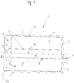
- figure 1 shows an example of a system 1 of the type presented here in a schematic longitudinal section, in which a coaxial cartridge 2 for pressing out the multi-component mass contained therein is inserted into a hollow-cylindrical receptacle of a support structure 3 .
- the coaxial cartridge 2 is made of plastic. The same can also apply to the support structure 3 .
- the cartridge 2 comprises a hollow-cylindrical inner wall 4 and a hollow-cylindrical outer wall 5 arranged around it with a common cylinder axis A, whereby an inner chamber 6 delimited radially by the inner wall 4 and an outer chamber 7 arranged radially between the inner wall 4 and the outer wall 5 are formed.
- a first component of the multi-component mass to be discharged is accommodated in the inner chamber 6
- a second component of the multi-component mass is accommodated in the outer chamber 7 .
- the cartridge 2 includes a cartridge cover 8, which in 1 right-hand end face of the cartridge 2 and thus the inner chamber 6 and the outer chamber 7 firmly closed, with one dispensing opening per chamber being formed in the cartridge cover 8 .
- the two discharge openings open into a connecting piece 9 of the cartridge cover 8, which is designed for connecting (e.g. by putting on or screwing on) a mixer (not shown) for mixing the first and the second component of the multi-component mass during the squeezing process.
- the cartridge 2 comprises an inner piston 10 which closes the rear of the inner chamber 6 and can be moved axially therein, and an outer piston 11 which closes the rear of the outer chamber 7 and can be moved axially 1 to the right, the multi-component mass can be pressed out of the cartridge 2 through the discharge openings of the cartridge cover 8.
- the inner wall 4 is thick-walled and therefore dimensionally stable so that it radially supports the inner bulb 10 and the outer bulb 11 and guides them through it, while the outer wall 5 is attached to the outer bulb 11 and the cartridge cover 8 and has such a thin wall that it extends through the movement of the outer piston 11 to the cartridge cover 8 when the mass is pressed out folds together and/or plastically deforms into the intermediate space 12 remaining between the outer wall 5 and the inside of the receptacle of the support structure 3 without any restoring force.
- the thin outer wall 5 of the cartridge 2 allows the cartridge 2 to be placed against the support structure 3 even at very low pressures and reduces the resilience of the outer wall 5 (pumping) considerably to completely due to the inelastic folding. Another advantage is the associated saving in material.
- the thin walls of the outer wall 5 can, in the best case, be as thick as a foil, as in 1 indicated schematically. This will cause an immediate plastic deformation when the cartridge 2 is pressed and thus completely avoid subsequent pumping.
- the film is connected directly to the inner piston 10 running on the inner wall 4 of the cartridge 2 and to the cartridge cover 8 by a weld in each case.
- the foil folds, for example, as in the already known foil packs within the support structure 3.
- the inner wall 4 of the cartridge 2 remains in place and guides the inner bulb 10 and the outer bulb 11.
Landscapes
- Engineering & Computer Science (AREA)
- Mechanical Engineering (AREA)
- Containers And Packaging Bodies Having A Special Means To Remove Contents (AREA)
Abstract
- eine hohlzylindrische Innenwand (4) und eine koaxial um diese angeordnete hohlzylindrische Außenwand (5), sodass die Kartusche (2) eine radial von der Innenwand (4) begrenzte Innenkammer (6) für eine erste Komponente und eine radial zwischen der Innenwand (4) und der Außenwand (5) angeordnete Außenkammer (7) für eine zweite Komponente der Mehrkomponentenmasse aufweist;
- einen Kartuschendeckel (8), der die Innen- und die Außenkammer (4, 5) an einer Stirnseite der Kartusche (2) verschließt und jeweils eine Ausbringöffnung pro Kammer aufweist; sowie
- einen die Innenkammer (4) rückseitig verschließenden und axial darin bewegbaren Innenkolben (10) und einen die Außenkammer (7) rückseitig verschließenden und axial bewegbaren Außenkolben (11);
- wobei die Innenwand (4) derart dickwandig ist, dass sie den Innen- und den Außenkolben (10, 11) radial abstützt und dadurch führt, während die Außenwand (5) am Außenkolben (11) und am Kartuschendeckel (8) befestigt ist und derart dünnwandig ist, dass sie sich durch das Bewegen des Außenkolbens (11) zum Kartuschendeckel (8) beim Auspressen der Masse rückstellkraftfrei zusammenfaltet.
Description
- Die Erfindung betrifft eine Koaxialkartusche, die zum Aufnehmen und Aufbewahren einer ersten und einer zweiten Komponente einer fließfähigen Mehrkomponentenmasse in voneinander getrennten koaxialen Kammern und zum Einlegen in eine Stützstruktur zum Auspressen der Masse aus der Kartusche ausgebildet ist.
- Im Stand der Technik sind verschiedene Kartuschenkonzepte bekannt, um mindestens zwei Komponenten an fließfähigen Massen in voneinander getrennten Kammern aufzunehmen, welche mittels eines Auspressgerätes ausgebracht werden können. Im Hinblick auf die Anordnung der Kammern wird zwischen Koaxialkartuschen sowie Kartuschen oder Foliengebinden mit nebeneinander angeordneten Einzelkartuschen oder Folienbeuteln für die verschiedenen Komponenten einer Mehrkomponentenmasse unterschieden. Bei der Mehrkomponentenmasse kann es sich beispielsweise um eine Dicht- oder Befestigungsmasse wie Mörtel, Klebstoff und vieles mehr handeln.
- Um eine hohe, gleichbleibende Mischqualität der beiden auszubringenden Massen zu gewährleisten, sind in den meisten Fällen geeignete Stützstrukturen für die Kartuschen zu verwenden, in welche die Kartuschen für den Auspressvorgang eingelegt werden. Diese Stützstrukturen nehmen beim Auspressvorgang die Drücke der Kartuschen auf und verhindern ein Ausdehnen der Kartuschen, die meist aus Kunststoff sind und daher einem hohen Druck beim Auspressvorgang ohne die Stützstruktur nachgeben würden.
- Koaxialkartuschen zeigen aufgrund eines nahezu gleich hohen Druckes in beiden Kammern und eines Überdrucks gegenüber dem außerhalb der Kartusche herrschenden Atmosphärendruck beim Auspressvorgang diese Ausdehnung in der Regel nur in der Außenwand der Kartusche. Dies kann zu Mischstörungen und entsprechend zu mangelndem Aushärteverhalten der beiden Massen führen:
Beim elastischen radialen Ausdehnen der Außenwand einer dickwandigen Kunststoffkartusche beim Auspressvorgang entstehen darin Rückstellkräfte. Diese können beim Unterbrechen des Auspressvorgangs - beispielsweise beim Übergang zum nächsten Bohrloch, wenn mehrere Bohrlöcher hintereinander mit dem Inhalt einer Kartusche befüllt werden sollen, - zu einem ungleichmäßigen Pumpverhalten in der Kartusche führen, von dem fast allein die Außenkammer betroffen ist. Dabei entlastet sich der Druck in der Außenkammer der Kartusche nach einem unterbrochenen Auspressvorgang entweder durch das Ausfließen der darin enthaltenen Komponente durch den Kartuschenauslass oder durch eine Entlastung des in dieser Kammer angeordneten Außenkolbens. Hierbei entsteht ein Kolbenversatz gegenüber der Innenkammer, was zu entsprechenden Mischstörungen beim nachfolgenden Auspressvorgang führt. Der ringförmige Außenkolben wird sich bei diesem störenden Pumpverhalten entsprechend dem Volumen eines etwaigen Ringspaltes zwischen der Stützstruktur und der Kartuschen-Außenwand zurückbewegen, in welchen sich die Außenwand beim Auspressvorgang elastisch verformt hatte. - Als Abhilfe hiergegen ist daher eine geeignete Stützstruktur zu verwenden, welche eine Deformation der Außenwand der Kartusche beim Auspressvorgang verhindern kann. Diese Stützstruktur muss dabei eng an der Kartusche anliegen, um das mögliche Pumpvolumen auf ein Minimum zu begrenzen. Auch ist dabei auf eine entsprechende Steifigkeit der Stützstruktur zu achten, um ein Pumpen aufgrund der Verformung der Stützstruktur selbst zu vermeiden. Identische Durchmesser (Innendurchmesser Stützstruktur = Außendurchmesser Kartusche) bieten dabei den größtmöglichen Schutz vor eventuellem Pumpen und damit einhergehender Mischstörung der auszubringenden Massen. Gleiche Durchmesser verhindern jedoch ein leichtes Einsetzen bzw. Entnehmen der Kartusche in/aus der Stützstruktur. Hierfür ist wiederum ein leicht größerer Innendurchmesser der Stützstruktur im Vergleich zum Außendurchmesser der Kartusche erforderlich, d. h. der oben genannte Ringspalt zwischen Kartusche und Stützstruktur, der das störende Pumpverhalten begünstigt. Gerade bei großvolumigen Kartuschen und Gebinden stellt das Pumpen eine große Herausforderung dar.
- Es ist daher Aufgabe der vorliegenden Erfindung, eine Koaxialkartusche zum Aufbewahren einer fließfähigen Mehrkomponentenmasse und zum Einlegen in eine Stützstruktur zum Auspressen der Masse aus der Kartusche sowie ein entsprechendes System aus einer Kartusche in Kombination mit einer Stützstruktur bereitzustellen, mit welchen das beschriebene störende, auf Rückstellkräften basierende Pumpverhalten der Kartusche reduziert oder sogar gänzlich verhindert werden kann.
- Diese Aufgabe wird durch eine Koaxialkartusche gemäß Anspruch 1 sowie durch ein entsprechendes System und Verfahren gemäß den nebengeordneten Ansprüchen gelöst. Weitere Ausgestaltungen sind in den abhängigen Ansprüchen angegeben. Alle in den Ansprüchen und der Beschreibung für die Kartusche genannten weiterführenden Merkmale und Wirkungen gelten dabei sinngemäß auch für das System und das Verfahren, wie auch umgekehrt.
- Gemäß einem ersten Aspekt ist eine Koaxialkartusche zum Aufbewahren einer fließfähigen Mehrkomponentenmasse und zum Einlegen in eine Stützstruktur zum Auspressen der Masse aus der Kartusche vorgesehen. Die Mehrkomponentenmasse umfasst dabei zumindest eine erste Komponente und eine zweite Komponente, die in der Kartusche getrennt voneinander aufbewahrt und erst beim Ausbringen aus der Kartusche miteinander vermischt werden sollen. Es kann sich hierbei insbesondere um eine Dicht- oder Befestigungsmasse wie Mörtel, Klebstoff und dergleichen handeln.
- Die Kartusche umfasst dabei eine hohlzylindrische Innenwand und eine koaxial (d. h. mit der gleichen Zylinderachse) um diese herum angeordnete hohlzylindrische Außenwand, sodass die Kartusche eine radial von der Innenwand begrenzte Innenkammer zum Aufnehmen der ersten Komponente der Mehrkomponentenmasse sowie eine radial zwischen der Innenwand und der Außenwand angeordnete Außenkammer zum Aufnehmen der zweiten Komponente der Mehrkomponentenmasse aufweist.
- An einer ihrer Stirnseiten weist die Kartusche ferner einen Kartuschendeckel auf, der die Innenkammer und die Außenkammer in axialer Richtung begrenzt und dabei eine Ausbringöffnung für die erste Komponente im Bereich der Innenkammer sowie eine Ausbringöffnung für die zweite Komponente im Bereich der Außenkammer aufweist. Der Kartuschendeckel kann insbesondere fest mit der Innen- und der Außenwand der Kartusche verbunden sein. Er kann hierzu beispielsweise zumindest mit der Innenwand einstückig ausgebildet sein.
- Weiterhin umfasst die Kartusche einen die Innenkammer rückseitig (d. h. zur anderen Stirnseite der Kartusche hin) verschließenden und axial darin bewegbaren Innenkolben sowie einen die Außenkammer ebenfalls rückseitig verschließenden und axial bewegbaren Außenkolben. Dabei ist die Innenwand der Kartusche derart formstabil, insbesondere dickwandig, ausgebildet, dass sie sowohl den Innenkolben als auch den Außenkolben radial abstützt und dadurch bei deren axialer Bewegung führt und die Zylinderform der Kartusche aufrechterhält.
- Die Außenwand der Kartusche ist einerseits mit dem Außenkolben und andererseits mit dem Kartuschendeckel fest verbunden. Im Gegensatz zu der Innenwand der Kartusche ist die Außenwand derart verformbar, insbesondere dünnwandig, ausgebildet, dass sie sich beim Auspressen der Mehrkomponentenmasse aus der Kartusche durch das axiale Verschieben des Außenkolbens zum Kartuschendeckel hin weitgehend unelastisch (mit anderen Worten rückstellkraftfrei, d. h. ohne Entstehung von Rückstellkräften) zusammenfaltet und/oder plastisch verformt.
- Die Wandstärken der Innenwand und der Außenwand sind dabei jeweils abhängig von den Gegebenheiten der spezifischen Anwendung - wie dem Material und der Dimensionierung der Kartusche - für die hierin beschriebene Funktionalität geeignet zu wählen.
- Eine Idee der Erfindung besteht somit in der Schaffung einer Koaxialkartusche, die eine dünnwandige Außenwand aufweist, welche sich beim bestimmungsgemäßen Auspressvorgang ohne Entstehung elastischer Rückstellkräfte verformen lässt. Dadurch lässt sich das eingangs beschriebene störende Pumpverhalten in der Außenwand der Kartusche in einer Stützstruktur erheblich reduzieren bis hin zu gänzlich verhindern. Ein weiterer Vorteil einer dünnen Außenwand ist die damit einhergehende Materialeinsparung.
- Eine dünne, rückstellkraftfrei verformbare Außenwandung der Kartusche lässt nämlich bereits bei sehr geringen Drücken in der Kartusche beim Auspressvorgang ein Anlegen der Außenwand an die Stützstruktur zu, wodurch das störende Rückstellverhalten der Außenwandung (Pumpen) erheblich reduziert ist. Die Innenwand der Kartusche bleibt dabei weitgehend formstabil stehen und führt den Innenkolben sowie den Außenkolben.
- Die genannte Dünnwandigkeit der Außenwand kann hierin im besten Fall bis hin zur Stärke einer Folie reichen. Dies wird eine sofortige plastische Verformung beim Anpressen der Kartusche verursachen und somit das nachträgliche Pumpen bei einer Unterbrechung des Auspressvorgangs gänzlich verhindern.
- Die Befestigung der Außenwand am Außenkolben und am Kartuschendeckel kann beispielsweise jeweils in deren Außenrandbereich sein. Eine Befestigung außen ist jedoch nicht zwingend. Die Außenwand, insbesondere wenn sie als Folie ausgebildet ist, kann auch innen angebracht werden. Auch ein Einspritzen der Folie in den Deckel oder Ringkolben (d. h. Außenkolben) ist möglich und kann je nach spezifischen Gegebenheiten einer Anwendung vorteilhaft sein.
- Gemäß einer Ausführungsform besitzen die hohlzylindrische Innenwand und die hohlzylindrische Außenwand jeweils einen kreisförmigen Querschnitt. Dies ist jedoch für das hierin dargelegte Funktionsprinzip nicht zwingend erforderlich, sodass grundsätzlich auch andere Querschnittsformen, wie beispielsweise elliptisch oder rechteckig, genauso gut implementierbar sind.
- Gemäß einer Ausführungsform sind zumindest die Innenwand und/oder die Außenwand der Kartusche aus Kunststoff mit entsprechend unterschiedlichen Wandstärken ausgebildet. Es kann insbesondere die gesamte Kartusche aus Kunststoff gefertigt sein, wobei deren einzelne Bestandteile aus dem gleichen oder unterschiedlichen Kunststoffarten sein können. Es können jedoch grundsätzlich auch andere Materialien, wie beispielsweise Metall für formstabile Bestandteile bzw. Metallfolie oder Gewebe oder Textil etc. für die unelastisch verformbare Außenwand, verwendet werden.
- Insbesondere kann die Außenwand der Kartusche durch eine Folie, beispielsweise eine Kunststofffolie, gebildet sein. Dabei kann die Folie einerseits am Außenkolben und andererseits am Kartuschendeckel angeschweißt und dadurch daran befestigt sein.
- Bei einer spezifischen Ausgestaltung weist der Kartuschendeckel auf seiner von der Innen- und der Außenkammer abgewandten Seite einen Anschlussstutzen auf, in den die Ausbringöffnungen der Innen- und der Außenkammer münden und der zum Anschließen eines Mischers zum Vermischen der ersten und der zweiten Komponente der Mehrkomponentenmasse beim Auspressvorgang ausgebildet ist. Dadurch können die verschiedenen Komponenten beim Auspressvorgang besonders effektiv zu der letztlich ausgebrachten Mehrkomponentenmasse vermischt werden.
- Gemäß einem weiteren Aspekt ist ein System zum Aufbewahren und Ausbringen einer fließfähigen Mehrkomponentenmasse vorgesehen. Das System umfasst zum einen eine Koaxialkartusche der hierin dargelegten Art und zum anderen eine Stützstruktur mit einer innenseitig zumindest abschnittsweise zylinderförmigen Aufnahme, deren Form und Größe zum Einlegen und Halten der Kartusche zum Auspressen der Mehrkomponentenmasse daraus bemessen sind.
- Dabei verbleibt zwischen der Innenseite der Aufnahme der Stützstruktur und der Außenwand der darin eingelegten Kartusche ein Zwischenraum zum Aufnehmen der sich beim Auspressen der Mehrkomponentenmasse aus der Kartusche zusammenfaltenden und/oder plastisch verformenden Außenwand der Kartusche. Im Gegensatz zu den herkömmlichen Koaxialkartuschen mit einer dicken, elastisch verformbaren Außenwand, wird bei dem vorliegend vorgestellten System durch das Vorhandensein dieses Zwischenraums kein störendes Rückstell- oder Pumpverhalten der Außenwand der Kartusche begünstigt, weil er gerade umgekehrt zum Aufnehmen der sich plastisch bzw. rückstellkraftfrei zusammenfaltenden Außenwand der Kartusche beim Auspressvorgang genutzt wird. Als weiterer Vorteil kann dieser Zwischenraum auch das Einlegen der Kartusche in die Stützstruktur erheblich erleichtern.
- Der genannte Zwischenraum zwischen der Innenseite der Aufnahme der Stützstruktur und der Außenseite der darin eingelegten Kartusche kann insbesondere einen zylindrischen Ringspalt und/oder eine oder mehrere radiale und/oder axiale Nuten einer vorbestimmten Form und Größe umfassen. Die Nuten sind in diesem Fall in der Innenseite der Aufnahme der Stützstruktur ausgebildet.
- Gemäß einer Ausführungsform umfasst das System ferner den weiter oben bereits erwähnten Mischer, der zum Anschließen an einem Anschlussstutzen des Kartuschendeckels und zum Vermischen der ersten und der zweiten Komponente der Mehrkomponentenmasse beim Auspressvorgang ausgebildet ist.
- Gemäß einem weiteren Aspekt ist ein Verfahren zum Auspressen einer fließfähigen Mehrkomponentenmasse aus der Koaxialkartusche eines Systems der hierin dargelegten Art vorgesehen. Das Verfahren umfasst dabei die Schritte:
- Einlegen der Kartusche, in deren Innen- und Außenkammer die erste bzw. zweite Komponente der auszubringenden Mehrkomponentenmasse aufgenommen sind, in die hierfür vorgesehene Aufnahme der Stützstruktur; und
- Auspressen der ersten Komponente aus der Innenkammer und der zweiten Komponente aus der Außenkammer durch ein gleichzeitiges axiales Bewegen des Innenkolbens und des Außenkolbens zum Kartuschendeckel hin. Bei dieser Bewegung schmiegt sich die Außenwand der Kartusche an die Innenseite der Aufnahme der Stützstruktur an und faltet sich in dem hierfür vorgesehenen Zwischenraum zusammen bzw. verformt sich darin plastisch.
- Die obigen Aspekte der Erfindung und deren Ausführungsformen und spezifische Ausgestaltungen werden nachfolgend anhand eines in der Zeichnung dargestellten Beispiels weiter erläutert. Die Zeichnung ist schematisch gehalten. Sie kann, muss jedoch nicht als maßstabsgetreu zu verstehen sein. Es zeigt:
- Figur 1
- einen Längsschnitt einer in einer Stützstruktur eingelegten Koaxialkartusche gemäß einem Ausführungsbeispiel eines Systems der hierin dargelegten Art zum Aufbewahren und Ausbringen einer fließfähigen Mehrkomponentenmasse.
- Alle weiter oben in der Beschreibung und in den nachfolgenden Ansprüchen erwähnten verschiedenen Ausführungsformen, Varianten und spezifischen Ausgestaltungsmerkmale der Kartusche, des Systems und des Verfahrens gemäß den obigen Aspekten der Erfindung können bei dem in
Fig. 1 gezeigten Beispiel implementiert sein, auch wenn sie nicht im Einzelnen dargestellt sind. Sie werden daher nachfolgend nicht alle nochmals wiederholt. Das Gleiche gilt entsprechend für die weiter oben bereits angegebenen Begriffsdefinitionen und Wirkungen in Bezug auf einzelne Merkmale, die in der Figur gezeigt sind. -
Figur 1 zeigt in einem schematischen Längsschnitt ein Beispiel eines Systems 1 der hierin dargelegten Art, in welchem eine Koaxialkartusche 2 zum Auspressen der darin aufgenommenen Mehrkomponentenmasse in eine hohlzylindrische Aufnahme einer Stützstruktur 3 eingelegt ist. In diesem Beispiel ist die Koaxialkartusche 2 aus Kunststoff gefertigt. Das Gleiche kann auch für die Stützstruktur 3 gelten. - Die Kartusche 2 umfasst eine hohlzylindrische Innenwand 4 und eine um diese herum angeordnete hohlzylindrische Außenwand 5 mit einer gemeinsamen Zylinderachse A, wodurch eine radial von der Innenwand 4 begrenzte Innenkammer 6 sowie eine radial zwischen der Innenwand 4 und der Außenwand 5 angeordnete Außenkammer 7 gebildet sind. In der Innenkammer 6 ist eine erste Komponente der auszubringenden Mehrkomponentenmasse aufgenommen, während in der Außenkammer 7 eine zweite Komponente der Mehrkomponentenmasse aufgenommen ist.
- Ferner umfasst die Kartusche 2 einen Kartuschendeckel 8 auf, der die in
Fig. 1 rechts liegende Stirnseite der Kartusche 2 und damit die Innenkammer 6 und die Außenkammer 7 fest verschließt, wobei jeweils eine Ausbringöffnung pro Kammer im Kartuschendeckel 8 ausgebildet ist. Die beiden Ausbringöffnungen münden in einen Anschlussstutzen 9 des Kartuschendeckels 8, der zum Anschließen (z. B. durch Aufsetzten oder Aufschrauben) eines Mischers (nicht dargestellt) zum Mischen der ersten und der zweiten Komponente der Mehrkomponentenmasse beim Auspressvorgang ausgebildet ist. - Des Weiteren umfasst die Kartusche 2 einen die Innenkammer 6 rückseitig verschließenden und axial darin bewegbaren Innenkolben 10 und einen die Außenkammer 7 rückseitig verschließenden und axial bewegbaren Außenkolben 11, durch deren axiale Bewegung in
Fig. 1 nach rechts die Mehrkomponentenmasse aus der Kartusche 2 durch die Ausbringöffnungen des Kartuschendeckels 8 ausgepresst werden können. - Dabei ist die Innenwand 4 derart dickwandig und dadurch formstabil ausgebildet, dass sie den Innenkolben 10 und den Außenkolben 11 radial abstützt und dadurch führt, während die Außenwand 5 am Außenkolben 11 und am Kartuschendeckel 8 befestigt ist und derart dünnwandig ausgebildet ist, dass sie sich durch das Bewegen des Außenkolbens 11 zum Kartuschendeckel 8 beim Auspressen der Masse rückstellkraftfrei in den zwischen der Außenwand 5 und der Innenseite der Aufnahme der Stützstruktur 3 verbleibenden Zwischenraum 12 zusammenfaltet und/oder plastisch verformt.
- Dabei lässt die dünne Außenwand 5 der Kartusche 2 bereits bei sehr geringen Drücken ein Anlegen der Kartusche 2 an die Stützstruktur 3 zu und reduziert durch das unelastische Zusammenfalten das Rückstellverhalten der Außenwand 5 (Pumpen) erheblich bis vollständig. Ein weiterer Vorteil ist die damit einhergehende Materialeinsparung.
- Die Dünnwandigkeit der Außenwand 5 kann im besten Fall bis hin zur Stärke einer Folie reichen, wie in
Fig. 1 schematisch angedeutet. Dies wird eine sofortige plastische Verformung beim Anpressen der Kartusche 2 verursachen und somit das nachträgliche Pumpen gänzlich vermeiden. In diesem Beispiel ist die Folie direkt mit dem auf der Innenwand 4 der Kartusche 2 laufenden Innenkolben 10 sowie mit dem Kartuschendeckel 8 jeweils durch eine Schweißung verbunden. - Beim Auspressvorgang faltet sich die Folie beispielsweise wie bei den bereits bekannten Foliengebinden innerhalb der Stützstruktur 3. Die Innenwand 4 der Kartusche 2 bleibt dabei stehen und führt den Innenkolben 10 und den Außenkolben 11.
Claims (10)
- Koaxialkartusche (2) zum Aufbewahren einer fließfähigen Mehrkomponentenmasse und zum Einlegen in eine Stützstruktur (3) zum Auspressen der Masse aus der Kartusche (2), umfassend:- eine hohlzylindrische Innenwand (4) und eine koaxial um diese herum angeordnete hohlzylindrische Außenwand (5), sodass die Kartusche (2) eine radial von der Innenwand (4) begrenzte Innenkammer (6) zum Aufnehmen einer ersten Komponente sowie eine radial zwischen der Innenwand (4) und der Außenwand (5) angeordnete Außenkammer (7) zum Aufnehmen einer zweiten Komponente der Mehrkomponentenmasse aufweist;- einen Kartuschendeckel (8), der die Innen- und die Außenkammer (6, 7) an einer Stirnseite der Kartusche (2) fest verschließt und jeweils eine Ausbringöffnung pro Kammer aufweist; sowie- einen die Innenkammer (6) rückseitig verschließenden und axial darin bewegbaren Innenkolben (10) und einen die Außenkammer (7) rückseitig verschließenden und axial bewegbaren Außenkolben (11);- wobei die Innenwand (4) derart formstabil, insbesondere dickwandig, ist, dass sie den Innen- und den Außenkolben (10, 11) radial abstützt und dadurch führt, während die Außenwand (5) am Außenkolben (11) und am Kartuschendeckel (8) befestigt ist und derart verformbar, insbesondere dünnwandig, ist, dass sie sich durch das Bewegen des Außenkolbens (11) zum Kartuschendeckel (8) beim Auspressen der Masse rückstellkraftfrei zusammenfaltet und/oder plastisch verformt.
- Koaxialkartusche (2) nach Anspruch 1, wobei- die hohlzylindrische Innenwand (4) und die hohlzylindrische Außenwand (5) jeweils einen kreisförmigen Querschnitt besitzen.
- Koaxialkartusche (2) nach Anspruch 1 oder 2, wobei- zumindest die Innenwand (4) und/oder die Außenwand (5) der Kartusche (2) aus Kunststoff mit entsprechend unterschiedlichen Wandstärken ausgebildet sind.
- Koaxialkartusche (2) nach einem der vorhergehenden Ansprüche, wobei- die Außenwand (5) der Kartusche (2) durch eine Folie gebildet ist.
- Koaxialkartusche (2) nach Anspruch 4, wobei- die Folie einerseits am Außenkolben (11) und andererseits am Kartuschendeckel (8) angeschweißt und dadurch daran befestigt ist.
- Koaxialkartusche (2) nach einem der vorhergehenden Ansprüche, wobei- der Kartuschendeckel (8) auf seiner von der Innen- und der Außenkammer (6, 7) abgewandten Seite einen Anschlussstutzen (9) aufweist, in den die Ausbringöffnungen der Innen- und der Außenkammer (6, 7) münden und der zum Anschließen eines Mischers zum Mischen der ersten und der zweiten Komponente der Mehrkomponentenmasse beim Auspressvorgang ausgebildet ist.
- System (1) zum Aufbewahren und Ausbringen einer fließfähigen Mehrkomponentenmasse, umfassend:- eine Koaxialkartusche (2) nach einem der vorhergehenden Ansprüche; und- eine Stützstruktur (3) mit einer innenseitig zumindest abschnittsweise zylinderförmigen Aufnahme, deren Form und Größe zum Einlegen und Halten der Koaxialkartusche (2) zum Auspressen der Mehrkomponentenmasse daraus bemessen sind,- wobei zwischen der Innenseite der Aufnahme der Stützstruktur (3) und der Außenwand (5) der darin eingelegten Kartusche (2) ein Zwischenraum (12) zum Aufnehmen der sich beim Auspressen der Masse aus der Kartusche (2) zusammenfaltenden und/oder plastisch verformenden Außenwand (5) der Kartusche (2) verbleibt.
- System (1) nach Anspruch 7, wobei- der Zwischenraum (12) einen zylindrischen Ringspalt und/oder eine oder mehrere radiale und/oder axiale Nuten einer vorbestimmten Form und Größe umfasst.
- System (1) nach Anspruch 7 oder 8, ferner umfassend- einen Mischer, der zum Anschließen an einem Anschlussstutzen (9) des Kartuschendeckels (8) und zum Mischen der ersten und der zweiten Komponente der Mehrkomponentenmasse beim Auspressvorgang ausgebildet ist.
- Verfahren zum Auspressen einer fließfähigen Mehrkomponentenmasse aus der Koaxialkartusche (2) eines Systems (1) nach einem der Ansprüche 7 bis 9, umfassend die Schritte:- Einlegen der Kartusche (2) in die hierfür vorgesehene Aufnahme der Stützstruktur (3); und- Auspressen der ersten Komponente aus der Innenkammer (6) und der zweiten Komponente aus der Außenkammer (7) durch ein simultanes axiales Bewegen des Innenkolbens (10) und des Außenkolbens (11) zum Kartuschendeckel (8) hin;- wobei sich die Außenwand (5) der Kartusche (2) bei dieser Bewegung an die Innenseite der Aufnahme der Stützstruktur (3) anschmiegt und in dem hierfür vorgesehenen Zwischenraum (12) zusammenfaltet und/oder plastisch verformt.
Priority Applications (1)
| Application Number | Priority Date | Filing Date | Title |
|---|---|---|---|
| EP21181303.5A EP4108597B1 (de) | 2021-06-24 | 2021-06-24 | Koaxialkartusche zum aufbewahren und rückstellkraftfreien auspressen einer fliessfähigen mehrkomponentenmasse |
Applications Claiming Priority (1)
| Application Number | Priority Date | Filing Date | Title |
|---|---|---|---|
| EP21181303.5A EP4108597B1 (de) | 2021-06-24 | 2021-06-24 | Koaxialkartusche zum aufbewahren und rückstellkraftfreien auspressen einer fliessfähigen mehrkomponentenmasse |
Publications (2)
| Publication Number | Publication Date |
|---|---|
| EP4108597A1 true EP4108597A1 (de) | 2022-12-28 |
| EP4108597B1 EP4108597B1 (de) | 2023-11-29 |
Family
ID=76920498
Family Applications (1)
| Application Number | Title | Priority Date | Filing Date |
|---|---|---|---|
| EP21181303.5A Active EP4108597B1 (de) | 2021-06-24 | 2021-06-24 | Koaxialkartusche zum aufbewahren und rückstellkraftfreien auspressen einer fliessfähigen mehrkomponentenmasse |
Country Status (1)
| Country | Link |
|---|---|
| EP (1) | EP4108597B1 (de) |
Citations (3)
| Publication number | Priority date | Publication date | Assignee | Title |
|---|---|---|---|---|
| US5564598A (en) * | 1991-07-15 | 1996-10-15 | James Owen Camm | Multiple component dispenser cartridge for dispensing guns |
| US20060144854A1 (en) * | 2004-12-30 | 2006-07-06 | Plas-Pak Industries, Inc. | Cartridge delivery system utilizing film bags |
| US20140203023A1 (en) * | 2011-10-17 | 2014-07-24 | Sulzer Mixpac Ag | Cartridge and multicomponent cartridge |
-
2021
- 2021-06-24 EP EP21181303.5A patent/EP4108597B1/de active Active
Patent Citations (3)
| Publication number | Priority date | Publication date | Assignee | Title |
|---|---|---|---|---|
| US5564598A (en) * | 1991-07-15 | 1996-10-15 | James Owen Camm | Multiple component dispenser cartridge for dispensing guns |
| US20060144854A1 (en) * | 2004-12-30 | 2006-07-06 | Plas-Pak Industries, Inc. | Cartridge delivery system utilizing film bags |
| US20140203023A1 (en) * | 2011-10-17 | 2014-07-24 | Sulzer Mixpac Ag | Cartridge and multicomponent cartridge |
Also Published As
| Publication number | Publication date |
|---|---|
| EP4108597B1 (de) | 2023-11-29 |
Similar Documents
| Publication | Publication Date | Title |
|---|---|---|
| EP1843952B1 (de) | Mehrkomponentenfolienbehaelter | |
| EP1140259B1 (de) | Mehrkammer-ampulle zum ausgeben eines aus mehreren substanzen bestehenden gemisches | |
| EP3102503B1 (de) | Kartusche und verfahren zum herstellen einer kartusche | |
| DE602004003563T2 (de) | Abgabevorrichtung | |
| EP3405293B1 (de) | Foliengebinde sowie baugruppe aus einer auspressvorrichtung und einem foliengebinde | |
| DE10347938B4 (de) | Kopfteil für einen Mehrkammerschlauchbeutel | |
| EP2868393A1 (de) | Austragsstössel, Austragseinrichtung umfassend den Austragsstössel und Verfahren | |
| EP3389876A1 (de) | Baugruppe aus einem foliengebinde und einer auspressvorrichtung sowie foliengebinde | |
| EP1514812A1 (de) | Kartusche mit entlüftbarem Kolben | |
| EP4151321B1 (de) | Stützstruktur mit variierendem innendurchmesser zum rückstellkraftfreien auspressen einer mehrkomponentenmasse aus einer koaxialkartusche | |
| EP4072740B1 (de) | Kartusche für eine auspressvorrichtung | |
| EP1607142A1 (de) | Vorrichtung zur Abgabe von zu verarbeitendem Material | |
| EP1676791B1 (de) | Mehrkammerkartusche für mehrkomponentige plastische Massen mit axial hintereinander angeordneten Kammern | |
| DE9100054U1 (de) | Vorratspackung für zweikomponentiges Polyurethanmaterial | |
| EP0352370B1 (de) | Verfahren und Einrichtung zum öffnen einer Verschlussmembran im Austritts stutzen einer Kartusche | |
| EP4108597B1 (de) | Koaxialkartusche zum aufbewahren und rückstellkraftfreien auspressen einer fliessfähigen mehrkomponentenmasse | |
| DE10207763A1 (de) | Mehrkomponenten-Kartusche | |
| WO2019110637A1 (de) | Verfahren und setzwerkzeug zum einsetzen eines kolbens in einen behälter | |
| EP4151554B1 (de) | Koaxialkartusche mit solldehnstellen zum rückstellkraftfreien auspressen einer fliessfähigen mehrkomponentenmasse | |
| EP4151322A1 (de) | Koaxialkartusche mit integrierter armierung zum rückstellkraftfreien auspressen einer fliessfähigen mehrkomponentenmasse | |
| EP2199228B1 (de) | Mehrkomponentenkartusche | |
| EP4108596A1 (de) | Set von koaxialkartuschen zum aufbewahren und auspressen einer zweikomponentenmasse mit unterschiedlichen mischverhältnissen | |
| EP2868392A1 (de) | Hülse, Austragseinrichtung umfassend die Hülse und Verfahren | |
| EP4365103B1 (de) | Mehrkammerkartusche | |
| WO1999026865A1 (de) | Kartusche für pastöse massen |
Legal Events
| Date | Code | Title | Description |
|---|---|---|---|
| PUAI | Public reference made under article 153(3) epc to a published international application that has entered the european phase |
Free format text: ORIGINAL CODE: 0009012 |
|
| STAA | Information on the status of an ep patent application or granted ep patent |
Free format text: STATUS: THE APPLICATION HAS BEEN PUBLISHED |
|
| AK | Designated contracting states |
Kind code of ref document: A1 Designated state(s): AL AT BE BG CH CY CZ DE DK EE ES FI FR GB GR HR HU IE IS IT LI LT LU LV MC MK MT NL NO PL PT RO RS SE SI SK SM TR |
|
| STAA | Information on the status of an ep patent application or granted ep patent |
Free format text: STATUS: REQUEST FOR EXAMINATION WAS MADE |
|
| 17P | Request for examination filed |
Effective date: 20230628 |
|
| RBV | Designated contracting states (corrected) |
Designated state(s): AL AT BE BG CH CY CZ DE DK EE ES FI FR GB GR HR HU IE IS IT LI LT LU LV MC MK MT NL NO PL PT RO RS SE SI SK SM TR |
|
| GRAP | Despatch of communication of intention to grant a patent |
Free format text: ORIGINAL CODE: EPIDOSNIGR1 |
|
| STAA | Information on the status of an ep patent application or granted ep patent |
Free format text: STATUS: GRANT OF PATENT IS INTENDED |
|
| INTG | Intention to grant announced |
Effective date: 20230922 |
|
| GRAS | Grant fee paid |
Free format text: ORIGINAL CODE: EPIDOSNIGR3 |
|
| GRAA | (expected) grant |
Free format text: ORIGINAL CODE: 0009210 |
|
| STAA | Information on the status of an ep patent application or granted ep patent |
Free format text: STATUS: THE PATENT HAS BEEN GRANTED |
|
| AK | Designated contracting states |
Kind code of ref document: B1 Designated state(s): AL AT BE BG CH CY CZ DE DK EE ES FI FR GB GR HR HU IE IS IT LI LT LU LV MC MK MT NL NO PL PT RO RS SE SI SK SM TR |
|
| REG | Reference to a national code |
Ref country code: GB Ref legal event code: FG4D Free format text: NOT ENGLISH |
|
| REG | Reference to a national code |
Ref country code: CH Ref legal event code: EP |
|
| REG | Reference to a national code |
Ref country code: DE Ref legal event code: R096 Ref document number: 502021002056 Country of ref document: DE |
|
| REG | Reference to a national code |
Ref country code: IE Ref legal event code: FG4D Free format text: LANGUAGE OF EP DOCUMENT: GERMAN |
|
| REG | Reference to a national code |
Ref country code: LT Ref legal event code: MG9D |
|
| REG | Reference to a national code |
Ref country code: NL Ref legal event code: MP Effective date: 20231129 |
|
| PG25 | Lapsed in a contracting state [announced via postgrant information from national office to epo] |
Ref country code: GR Free format text: LAPSE BECAUSE OF FAILURE TO SUBMIT A TRANSLATION OF THE DESCRIPTION OR TO PAY THE FEE WITHIN THE PRESCRIBED TIME-LIMIT Effective date: 20240301 |
|
| PG25 | Lapsed in a contracting state [announced via postgrant information from national office to epo] |
Ref country code: IS Free format text: LAPSE BECAUSE OF FAILURE TO SUBMIT A TRANSLATION OF THE DESCRIPTION OR TO PAY THE FEE WITHIN THE PRESCRIBED TIME-LIMIT Effective date: 20240329 |
|
| PG25 | Lapsed in a contracting state [announced via postgrant information from national office to epo] |
Ref country code: LT Free format text: LAPSE BECAUSE OF FAILURE TO SUBMIT A TRANSLATION OF THE DESCRIPTION OR TO PAY THE FEE WITHIN THE PRESCRIBED TIME-LIMIT Effective date: 20231129 |
|
| PG25 | Lapsed in a contracting state [announced via postgrant information from national office to epo] |
Ref country code: ES Free format text: LAPSE BECAUSE OF FAILURE TO SUBMIT A TRANSLATION OF THE DESCRIPTION OR TO PAY THE FEE WITHIN THE PRESCRIBED TIME-LIMIT Effective date: 20231129 |
|
| PG25 | Lapsed in a contracting state [announced via postgrant information from national office to epo] |
Ref country code: LT Free format text: LAPSE BECAUSE OF FAILURE TO SUBMIT A TRANSLATION OF THE DESCRIPTION OR TO PAY THE FEE WITHIN THE PRESCRIBED TIME-LIMIT Effective date: 20231129 Ref country code: IS Free format text: LAPSE BECAUSE OF FAILURE TO SUBMIT A TRANSLATION OF THE DESCRIPTION OR TO PAY THE FEE WITHIN THE PRESCRIBED TIME-LIMIT Effective date: 20240329 Ref country code: GR Free format text: LAPSE BECAUSE OF FAILURE TO SUBMIT A TRANSLATION OF THE DESCRIPTION OR TO PAY THE FEE WITHIN THE PRESCRIBED TIME-LIMIT Effective date: 20240301 Ref country code: ES Free format text: LAPSE BECAUSE OF FAILURE TO SUBMIT A TRANSLATION OF THE DESCRIPTION OR TO PAY THE FEE WITHIN THE PRESCRIBED TIME-LIMIT Effective date: 20231129 Ref country code: BG Free format text: LAPSE BECAUSE OF FAILURE TO SUBMIT A TRANSLATION OF THE DESCRIPTION OR TO PAY THE FEE WITHIN THE PRESCRIBED TIME-LIMIT Effective date: 20240229 |
|
| PG25 | Lapsed in a contracting state [announced via postgrant information from national office to epo] |
Ref country code: NL Free format text: LAPSE BECAUSE OF FAILURE TO SUBMIT A TRANSLATION OF THE DESCRIPTION OR TO PAY THE FEE WITHIN THE PRESCRIBED TIME-LIMIT Effective date: 20231129 |
|
| PG25 | Lapsed in a contracting state [announced via postgrant information from national office to epo] |
Ref country code: SE Free format text: LAPSE BECAUSE OF FAILURE TO SUBMIT A TRANSLATION OF THE DESCRIPTION OR TO PAY THE FEE WITHIN THE PRESCRIBED TIME-LIMIT Effective date: 20231129 Ref country code: RS Free format text: LAPSE BECAUSE OF FAILURE TO SUBMIT A TRANSLATION OF THE DESCRIPTION OR TO PAY THE FEE WITHIN THE PRESCRIBED TIME-LIMIT Effective date: 20231129 Ref country code: PL Free format text: LAPSE BECAUSE OF FAILURE TO SUBMIT A TRANSLATION OF THE DESCRIPTION OR TO PAY THE FEE WITHIN THE PRESCRIBED TIME-LIMIT Effective date: 20231129 Ref country code: NO Free format text: LAPSE BECAUSE OF FAILURE TO SUBMIT A TRANSLATION OF THE DESCRIPTION OR TO PAY THE FEE WITHIN THE PRESCRIBED TIME-LIMIT Effective date: 20240229 Ref country code: NL Free format text: LAPSE BECAUSE OF FAILURE TO SUBMIT A TRANSLATION OF THE DESCRIPTION OR TO PAY THE FEE WITHIN THE PRESCRIBED TIME-LIMIT Effective date: 20231129 Ref country code: LV Free format text: LAPSE BECAUSE OF FAILURE TO SUBMIT A TRANSLATION OF THE DESCRIPTION OR TO PAY THE FEE WITHIN THE PRESCRIBED TIME-LIMIT Effective date: 20231129 Ref country code: HR Free format text: LAPSE BECAUSE OF FAILURE TO SUBMIT A TRANSLATION OF THE DESCRIPTION OR TO PAY THE FEE WITHIN THE PRESCRIBED TIME-LIMIT Effective date: 20231129 |
|
| PG25 | Lapsed in a contracting state [announced via postgrant information from national office to epo] |
Ref country code: DK Free format text: LAPSE BECAUSE OF FAILURE TO SUBMIT A TRANSLATION OF THE DESCRIPTION OR TO PAY THE FEE WITHIN THE PRESCRIBED TIME-LIMIT Effective date: 20231129 |
|
| PG25 | Lapsed in a contracting state [announced via postgrant information from national office to epo] |
Ref country code: CZ Free format text: LAPSE BECAUSE OF FAILURE TO SUBMIT A TRANSLATION OF THE DESCRIPTION OR TO PAY THE FEE WITHIN THE PRESCRIBED TIME-LIMIT Effective date: 20231129 |
|
| PG25 | Lapsed in a contracting state [announced via postgrant information from national office to epo] |
Ref country code: SK Free format text: LAPSE BECAUSE OF FAILURE TO SUBMIT A TRANSLATION OF THE DESCRIPTION OR TO PAY THE FEE WITHIN THE PRESCRIBED TIME-LIMIT Effective date: 20231129 |
|
| PG25 | Lapsed in a contracting state [announced via postgrant information from national office to epo] |
Ref country code: SM Free format text: LAPSE BECAUSE OF FAILURE TO SUBMIT A TRANSLATION OF THE DESCRIPTION OR TO PAY THE FEE WITHIN THE PRESCRIBED TIME-LIMIT Effective date: 20231129 Ref country code: SK Free format text: LAPSE BECAUSE OF FAILURE TO SUBMIT A TRANSLATION OF THE DESCRIPTION OR TO PAY THE FEE WITHIN THE PRESCRIBED TIME-LIMIT Effective date: 20231129 Ref country code: RO Free format text: LAPSE BECAUSE OF FAILURE TO SUBMIT A TRANSLATION OF THE DESCRIPTION OR TO PAY THE FEE WITHIN THE PRESCRIBED TIME-LIMIT Effective date: 20231129 Ref country code: IT Free format text: LAPSE BECAUSE OF FAILURE TO SUBMIT A TRANSLATION OF THE DESCRIPTION OR TO PAY THE FEE WITHIN THE PRESCRIBED TIME-LIMIT Effective date: 20231129 Ref country code: EE Free format text: LAPSE BECAUSE OF FAILURE TO SUBMIT A TRANSLATION OF THE DESCRIPTION OR TO PAY THE FEE WITHIN THE PRESCRIBED TIME-LIMIT Effective date: 20231129 Ref country code: DK Free format text: LAPSE BECAUSE OF FAILURE TO SUBMIT A TRANSLATION OF THE DESCRIPTION OR TO PAY THE FEE WITHIN THE PRESCRIBED TIME-LIMIT Effective date: 20231129 Ref country code: CZ Free format text: LAPSE BECAUSE OF FAILURE TO SUBMIT A TRANSLATION OF THE DESCRIPTION OR TO PAY THE FEE WITHIN THE PRESCRIBED TIME-LIMIT Effective date: 20231129 |
|
| PG25 | Lapsed in a contracting state [announced via postgrant information from national office to epo] |
Ref country code: PT Free format text: LAPSE BECAUSE OF FAILURE TO SUBMIT A TRANSLATION OF THE DESCRIPTION OR TO PAY THE FEE WITHIN THE PRESCRIBED TIME-LIMIT Effective date: 20240401 |
|
| PG25 | Lapsed in a contracting state [announced via postgrant information from national office to epo] |
Ref country code: PT Free format text: LAPSE BECAUSE OF FAILURE TO SUBMIT A TRANSLATION OF THE DESCRIPTION OR TO PAY THE FEE WITHIN THE PRESCRIBED TIME-LIMIT Effective date: 20240401 |
|
| REG | Reference to a national code |
Ref country code: DE Ref legal event code: R097 Ref document number: 502021002056 Country of ref document: DE |
|
| PLBE | No opposition filed within time limit |
Free format text: ORIGINAL CODE: 0009261 |
|
| STAA | Information on the status of an ep patent application or granted ep patent |
Free format text: STATUS: NO OPPOSITION FILED WITHIN TIME LIMIT |
|
| PG25 | Lapsed in a contracting state [announced via postgrant information from national office to epo] |
Ref country code: SI Free format text: LAPSE BECAUSE OF FAILURE TO SUBMIT A TRANSLATION OF THE DESCRIPTION OR TO PAY THE FEE WITHIN THE PRESCRIBED TIME-LIMIT Effective date: 20231129 |
|
| PG25 | Lapsed in a contracting state [announced via postgrant information from national office to epo] |
Ref country code: SI Free format text: LAPSE BECAUSE OF FAILURE TO SUBMIT A TRANSLATION OF THE DESCRIPTION OR TO PAY THE FEE WITHIN THE PRESCRIBED TIME-LIMIT Effective date: 20231129 |
|
| 26N | No opposition filed |
Effective date: 20240830 |
|
| PG25 | Lapsed in a contracting state [announced via postgrant information from national office to epo] |
Ref country code: MC Free format text: LAPSE BECAUSE OF FAILURE TO SUBMIT A TRANSLATION OF THE DESCRIPTION OR TO PAY THE FEE WITHIN THE PRESCRIBED TIME-LIMIT Effective date: 20231129 |
|
| PG25 | Lapsed in a contracting state [announced via postgrant information from national office to epo] |
Ref country code: LU Free format text: LAPSE BECAUSE OF NON-PAYMENT OF DUE FEES Effective date: 20240624 |
|
| PG25 | Lapsed in a contracting state [announced via postgrant information from national office to epo] |
Ref country code: IE Free format text: LAPSE BECAUSE OF NON-PAYMENT OF DUE FEES Effective date: 20240624 |
|
| PG25 | Lapsed in a contracting state [announced via postgrant information from national office to epo] |
Ref country code: BE Free format text: LAPSE BECAUSE OF NON-PAYMENT OF DUE FEES Effective date: 20240630 |
|
| PG25 | Lapsed in a contracting state [announced via postgrant information from national office to epo] |
Ref country code: FR Free format text: LAPSE BECAUSE OF NON-PAYMENT OF DUE FEES Effective date: 20240630 |
|
| REG | Reference to a national code |
Ref country code: BE Ref legal event code: MM Effective date: 20240630 |
|
| PGFP | Annual fee paid to national office [announced via postgrant information from national office to epo] |
Ref country code: DE Payment date: 20250618 Year of fee payment: 5 |
|
| PGFP | Annual fee paid to national office [announced via postgrant information from national office to epo] |
Ref country code: GB Payment date: 20250618 Year of fee payment: 5 |
|
| PGFP | Annual fee paid to national office [announced via postgrant information from national office to epo] |
Ref country code: AT Payment date: 20250721 Year of fee payment: 5 |
|
| PG25 | Lapsed in a contracting state [announced via postgrant information from national office to epo] |
Ref country code: FI Free format text: LAPSE BECAUSE OF FAILURE TO SUBMIT A TRANSLATION OF THE DESCRIPTION OR TO PAY THE FEE WITHIN THE PRESCRIBED TIME-LIMIT Effective date: 20231129 |
|
| PGFP | Annual fee paid to national office [announced via postgrant information from national office to epo] |
Ref country code: CH Payment date: 20250701 Year of fee payment: 5 |
|
| PG25 | Lapsed in a contracting state [announced via postgrant information from national office to epo] |
Ref country code: CY Free format text: LAPSE BECAUSE OF FAILURE TO SUBMIT A TRANSLATION OF THE DESCRIPTION OR TO PAY THE FEE WITHIN THE PRESCRIBED TIME-LIMIT; INVALID AB INITIO Effective date: 20210624 |
|
| PG25 | Lapsed in a contracting state [announced via postgrant information from national office to epo] |
Ref country code: HU Free format text: LAPSE BECAUSE OF FAILURE TO SUBMIT A TRANSLATION OF THE DESCRIPTION OR TO PAY THE FEE WITHIN THE PRESCRIBED TIME-LIMIT; INVALID AB INITIO Effective date: 20210624 |