EP4108562B1 - Floating body - Google Patents
Floating body Download PDFInfo
- Publication number
- EP4108562B1 EP4108562B1 EP21886317.3A EP21886317A EP4108562B1 EP 4108562 B1 EP4108562 B1 EP 4108562B1 EP 21886317 A EP21886317 A EP 21886317A EP 4108562 B1 EP4108562 B1 EP 4108562B1
- Authority
- EP
- European Patent Office
- Prior art keywords
- tank
- carbon dioxide
- heat exchanger
- gas
- heat
- Prior art date
- Legal status (The legal status is an assumption and is not a legal conclusion. Google has not performed a legal analysis and makes no representation as to the accuracy of the status listed.)
- Active
Links
Images


Classifications
-
- B—PERFORMING OPERATIONS; TRANSPORTING
- B63—SHIPS OR OTHER WATERBORNE VESSELS; RELATED EQUIPMENT
- B63B—SHIPS OR OTHER WATERBORNE VESSELS; EQUIPMENT FOR SHIPPING
- B63B11/00—Interior subdivision of hulls
- B63B11/04—Constructional features of bunkers, e.g. structural fuel tanks, or ballast tanks, e.g. with elastic walls
-
- B—PERFORMING OPERATIONS; TRANSPORTING
- B63—SHIPS OR OTHER WATERBORNE VESSELS; RELATED EQUIPMENT
- B63B—SHIPS OR OTHER WATERBORNE VESSELS; EQUIPMENT FOR SHIPPING
- B63B25/00—Load-accommodating arrangements, e.g. stowing, trimming; Vessels characterised thereby
- B63B25/02—Load-accommodating arrangements, e.g. stowing, trimming; Vessels characterised thereby for bulk goods
- B63B25/08—Load-accommodating arrangements, e.g. stowing, trimming; Vessels characterised thereby for bulk goods fluid
- B63B25/12—Load-accommodating arrangements, e.g. stowing, trimming; Vessels characterised thereby for bulk goods fluid closed
- B63B25/16—Load-accommodating arrangements, e.g. stowing, trimming; Vessels characterised thereby for bulk goods fluid closed heat-insulated
-
- B—PERFORMING OPERATIONS; TRANSPORTING
- B63—SHIPS OR OTHER WATERBORNE VESSELS; RELATED EQUIPMENT
- B63H—MARINE PROPULSION OR STEERING
- B63H21/00—Use of propulsion power plant or units on vessels
- B63H21/38—Apparatus or methods specially adapted for use on marine vessels, for handling power plant or unit liquids, e.g. lubricants, coolants, fuels or the like
-
- B—PERFORMING OPERATIONS; TRANSPORTING
- B63—SHIPS OR OTHER WATERBORNE VESSELS; RELATED EQUIPMENT
- B63J—AUXILIARIES ON VESSELS
- B63J2/00—Arrangements of ventilation, heating, cooling, or air-conditioning
- B63J2/12—Heating; Cooling
- B63J2/14—Heating; Cooling of liquid-freight-carrying tanks
-
- F—MECHANICAL ENGINEERING; LIGHTING; HEATING; WEAPONS; BLASTING
- F17—STORING OR DISTRIBUTING GASES OR LIQUIDS
- F17C—VESSELS FOR CONTAINING OR STORING COMPRESSED, LIQUEFIED OR SOLIDIFIED GASES; FIXED-CAPACITY GAS-HOLDERS; FILLING VESSELS WITH, OR DISCHARGING FROM VESSELS, COMPRESSED, LIQUEFIED, OR SOLIDIFIED GASES
- F17C9/00—Methods or apparatus for discharging liquefied or solidified gases from vessels not under pressure
- F17C9/02—Methods or apparatus for discharging liquefied or solidified gases from vessels not under pressure with change of state, e.g. vaporisation
-
- F—MECHANICAL ENGINEERING; LIGHTING; HEATING; WEAPONS; BLASTING
- F25—REFRIGERATION OR COOLING; COMBINED HEATING AND REFRIGERATION SYSTEMS; HEAT PUMP SYSTEMS; MANUFACTURE OR STORAGE OF ICE; LIQUEFACTION SOLIDIFICATION OF GASES
- F25J—LIQUEFACTION, SOLIDIFICATION OR SEPARATION OF GASES OR GASEOUS OR LIQUEFIED GASEOUS MIXTURES BY PRESSURE AND COLD TREATMENT OR BY BRINGING THEM INTO THE SUPERCRITICAL STATE
- F25J1/00—Processes or apparatus for liquefying or solidifying gases or gaseous mixtures
- F25J1/0002—Processes or apparatus for liquefying or solidifying gases or gaseous mixtures characterised by the fluid to be liquefied
- F25J1/0027—Oxides of carbon, e.g. CO2
-
- F—MECHANICAL ENGINEERING; LIGHTING; HEATING; WEAPONS; BLASTING
- F25—REFRIGERATION OR COOLING; COMBINED HEATING AND REFRIGERATION SYSTEMS; HEAT PUMP SYSTEMS; MANUFACTURE OR STORAGE OF ICE; LIQUEFACTION SOLIDIFICATION OF GASES
- F25J—LIQUEFACTION, SOLIDIFICATION OR SEPARATION OF GASES OR GASEOUS OR LIQUEFIED GASEOUS MIXTURES BY PRESSURE AND COLD TREATMENT OR BY BRINGING THEM INTO THE SUPERCRITICAL STATE
- F25J1/00—Processes or apparatus for liquefying or solidifying gases or gaseous mixtures
- F25J1/003—Processes or apparatus for liquefying or solidifying gases or gaseous mixtures characterised by the kind of cold generation within the liquefaction unit for compensating heat leaks and liquid production
- F25J1/0047—Processes or apparatus for liquefying or solidifying gases or gaseous mixtures characterised by the kind of cold generation within the liquefaction unit for compensating heat leaks and liquid production using an "external" refrigerant stream in a closed vapor compression cycle
- F25J1/0052—Processes or apparatus for liquefying or solidifying gases or gaseous mixtures characterised by the kind of cold generation within the liquefaction unit for compensating heat leaks and liquid production using an "external" refrigerant stream in a closed vapor compression cycle by vaporising a liquid refrigerant stream
-
- F—MECHANICAL ENGINEERING; LIGHTING; HEATING; WEAPONS; BLASTING
- F25—REFRIGERATION OR COOLING; COMBINED HEATING AND REFRIGERATION SYSTEMS; HEAT PUMP SYSTEMS; MANUFACTURE OR STORAGE OF ICE; LIQUEFACTION SOLIDIFICATION OF GASES
- F25J—LIQUEFACTION, SOLIDIFICATION OR SEPARATION OF GASES OR GASEOUS OR LIQUEFIED GASEOUS MIXTURES BY PRESSURE AND COLD TREATMENT OR BY BRINGING THEM INTO THE SUPERCRITICAL STATE
- F25J1/00—Processes or apparatus for liquefying or solidifying gases or gaseous mixtures
- F25J1/006—Processes or apparatus for liquefying or solidifying gases or gaseous mixtures characterised by the refrigerant fluid used
-
- F—MECHANICAL ENGINEERING; LIGHTING; HEATING; WEAPONS; BLASTING
- F25—REFRIGERATION OR COOLING; COMBINED HEATING AND REFRIGERATION SYSTEMS; HEAT PUMP SYSTEMS; MANUFACTURE OR STORAGE OF ICE; LIQUEFACTION SOLIDIFICATION OF GASES
- F25J—LIQUEFACTION, SOLIDIFICATION OR SEPARATION OF GASES OR GASEOUS OR LIQUEFIED GASEOUS MIXTURES BY PRESSURE AND COLD TREATMENT OR BY BRINGING THEM INTO THE SUPERCRITICAL STATE
- F25J1/00—Processes or apparatus for liquefying or solidifying gases or gaseous mixtures
- F25J1/02—Processes or apparatus for liquefying or solidifying gases or gaseous mixtures requiring the use of refrigeration, e.g. of helium or hydrogen ; Details and kind of the refrigeration system used; Integration with other units or processes; Controlling aspects of the process
- F25J1/0203—Processes or apparatus for liquefying or solidifying gases or gaseous mixtures requiring the use of refrigeration, e.g. of helium or hydrogen ; Details and kind of the refrigeration system used; Integration with other units or processes; Controlling aspects of the process using a single-component refrigerant [SCR] fluid in a closed vapor compression cycle
- F25J1/0204—Processes or apparatus for liquefying or solidifying gases or gaseous mixtures requiring the use of refrigeration, e.g. of helium or hydrogen ; Details and kind of the refrigeration system used; Integration with other units or processes; Controlling aspects of the process using a single-component refrigerant [SCR] fluid in a closed vapor compression cycle as a single flow SCR cycle
-
- F—MECHANICAL ENGINEERING; LIGHTING; HEATING; WEAPONS; BLASTING
- F25—REFRIGERATION OR COOLING; COMBINED HEATING AND REFRIGERATION SYSTEMS; HEAT PUMP SYSTEMS; MANUFACTURE OR STORAGE OF ICE; LIQUEFACTION SOLIDIFICATION OF GASES
- F25J—LIQUEFACTION, SOLIDIFICATION OR SEPARATION OF GASES OR GASEOUS OR LIQUEFIED GASEOUS MIXTURES BY PRESSURE AND COLD TREATMENT OR BY BRINGING THEM INTO THE SUPERCRITICAL STATE
- F25J1/00—Processes or apparatus for liquefying or solidifying gases or gaseous mixtures
- F25J1/02—Processes or apparatus for liquefying or solidifying gases or gaseous mixtures requiring the use of refrigeration, e.g. of helium or hydrogen ; Details and kind of the refrigeration system used; Integration with other units or processes; Controlling aspects of the process
- F25J1/0221—Processes or apparatus for liquefying or solidifying gases or gaseous mixtures requiring the use of refrigeration, e.g. of helium or hydrogen ; Details and kind of the refrigeration system used; Integration with other units or processes; Controlling aspects of the process using the cold stored in an external cryogenic component in an open refrigeration loop
-
- F—MECHANICAL ENGINEERING; LIGHTING; HEATING; WEAPONS; BLASTING
- F25—REFRIGERATION OR COOLING; COMBINED HEATING AND REFRIGERATION SYSTEMS; HEAT PUMP SYSTEMS; MANUFACTURE OR STORAGE OF ICE; LIQUEFACTION SOLIDIFICATION OF GASES
- F25J—LIQUEFACTION, SOLIDIFICATION OR SEPARATION OF GASES OR GASEOUS OR LIQUEFIED GASEOUS MIXTURES BY PRESSURE AND COLD TREATMENT OR BY BRINGING THEM INTO THE SUPERCRITICAL STATE
- F25J1/00—Processes or apparatus for liquefying or solidifying gases or gaseous mixtures
- F25J1/02—Processes or apparatus for liquefying or solidifying gases or gaseous mixtures requiring the use of refrigeration, e.g. of helium or hydrogen ; Details and kind of the refrigeration system used; Integration with other units or processes; Controlling aspects of the process
- F25J1/0221—Processes or apparatus for liquefying or solidifying gases or gaseous mixtures requiring the use of refrigeration, e.g. of helium or hydrogen ; Details and kind of the refrigeration system used; Integration with other units or processes; Controlling aspects of the process using the cold stored in an external cryogenic component in an open refrigeration loop
- F25J1/0222—Processes or apparatus for liquefying or solidifying gases or gaseous mixtures requiring the use of refrigeration, e.g. of helium or hydrogen ; Details and kind of the refrigeration system used; Integration with other units or processes; Controlling aspects of the process using the cold stored in an external cryogenic component in an open refrigeration loop in combination with an intermediate heat exchange fluid between the cryogenic component and the fluid to be liquefied
-
- F—MECHANICAL ENGINEERING; LIGHTING; HEATING; WEAPONS; BLASTING
- F25—REFRIGERATION OR COOLING; COMBINED HEATING AND REFRIGERATION SYSTEMS; HEAT PUMP SYSTEMS; MANUFACTURE OR STORAGE OF ICE; LIQUEFACTION SOLIDIFICATION OF GASES
- F25J—LIQUEFACTION, SOLIDIFICATION OR SEPARATION OF GASES OR GASEOUS OR LIQUEFIED GASEOUS MIXTURES BY PRESSURE AND COLD TREATMENT OR BY BRINGING THEM INTO THE SUPERCRITICAL STATE
- F25J1/00—Processes or apparatus for liquefying or solidifying gases or gaseous mixtures
- F25J1/02—Processes or apparatus for liquefying or solidifying gases or gaseous mixtures requiring the use of refrigeration, e.g. of helium or hydrogen ; Details and kind of the refrigeration system used; Integration with other units or processes; Controlling aspects of the process
- F25J1/0243—Start-up or control of the process; Details of the apparatus used; Details of the refrigerant compression system used
- F25J1/0257—Construction and layout of liquefaction equipments, e.g. valves, machines
- F25J1/0262—Details of the cold heat exchange system
-
- F—MECHANICAL ENGINEERING; LIGHTING; HEATING; WEAPONS; BLASTING
- F25—REFRIGERATION OR COOLING; COMBINED HEATING AND REFRIGERATION SYSTEMS; HEAT PUMP SYSTEMS; MANUFACTURE OR STORAGE OF ICE; LIQUEFACTION SOLIDIFICATION OF GASES
- F25J—LIQUEFACTION, SOLIDIFICATION OR SEPARATION OF GASES OR GASEOUS OR LIQUEFIED GASEOUS MIXTURES BY PRESSURE AND COLD TREATMENT OR BY BRINGING THEM INTO THE SUPERCRITICAL STATE
- F25J1/00—Processes or apparatus for liquefying or solidifying gases or gaseous mixtures
- F25J1/02—Processes or apparatus for liquefying or solidifying gases or gaseous mixtures requiring the use of refrigeration, e.g. of helium or hydrogen ; Details and kind of the refrigeration system used; Integration with other units or processes; Controlling aspects of the process
- F25J1/0243—Start-up or control of the process; Details of the apparatus used; Details of the refrigerant compression system used
- F25J1/0257—Construction and layout of liquefaction equipments, e.g. valves, machines
- F25J1/0262—Details of the cold heat exchange system
- F25J1/0264—Arrangement of heat exchanger cores in parallel with different functions, e.g. different cooling streams
- F25J1/0265—Arrangement of heat exchanger cores in parallel with different functions, e.g. different cooling streams comprising cores associated exclusively with the cooling of a refrigerant stream, e.g. for auto-refrigeration or economizer
- F25J1/0268—Arrangement of heat exchanger cores in parallel with different functions, e.g. different cooling streams comprising cores associated exclusively with the cooling of a refrigerant stream, e.g. for auto-refrigeration or economizer using a dedicated refrigeration means
-
- F—MECHANICAL ENGINEERING; LIGHTING; HEATING; WEAPONS; BLASTING
- F25—REFRIGERATION OR COOLING; COMBINED HEATING AND REFRIGERATION SYSTEMS; HEAT PUMP SYSTEMS; MANUFACTURE OR STORAGE OF ICE; LIQUEFACTION SOLIDIFICATION OF GASES
- F25J—LIQUEFACTION, SOLIDIFICATION OR SEPARATION OF GASES OR GASEOUS OR LIQUEFIED GASEOUS MIXTURES BY PRESSURE AND COLD TREATMENT OR BY BRINGING THEM INTO THE SUPERCRITICAL STATE
- F25J1/00—Processes or apparatus for liquefying or solidifying gases or gaseous mixtures
- F25J1/02—Processes or apparatus for liquefying or solidifying gases or gaseous mixtures requiring the use of refrigeration, e.g. of helium or hydrogen ; Details and kind of the refrigeration system used; Integration with other units or processes; Controlling aspects of the process
- F25J1/0243—Start-up or control of the process; Details of the apparatus used; Details of the refrigerant compression system used
- F25J1/0257—Construction and layout of liquefaction equipments, e.g. valves, machines
- F25J1/0275—Construction and layout of liquefaction equipments, e.g. valves, machines adapted for special use of the liquefaction unit, e.g. portable or transportable devices
- F25J1/0277—Offshore use, e.g. during shipping
-
- F—MECHANICAL ENGINEERING; LIGHTING; HEATING; WEAPONS; BLASTING
- F17—STORING OR DISTRIBUTING GASES OR LIQUIDS
- F17C—VESSELS FOR CONTAINING OR STORING COMPRESSED, LIQUEFIED OR SOLIDIFIED GASES; FIXED-CAPACITY GAS-HOLDERS; FILLING VESSELS WITH, OR DISCHARGING FROM VESSELS, COMPRESSED, LIQUEFIED, OR SOLIDIFIED GASES
- F17C2221/00—Handled fluid, in particular type of fluid
- F17C2221/03—Mixtures
- F17C2221/032—Hydrocarbons
- F17C2221/033—Methane, e.g. natural gas, CNG, LNG, GNL, GNC, PLNG
-
- F—MECHANICAL ENGINEERING; LIGHTING; HEATING; WEAPONS; BLASTING
- F17—STORING OR DISTRIBUTING GASES OR LIQUIDS
- F17C—VESSELS FOR CONTAINING OR STORING COMPRESSED, LIQUEFIED OR SOLIDIFIED GASES; FIXED-CAPACITY GAS-HOLDERS; FILLING VESSELS WITH, OR DISCHARGING FROM VESSELS, COMPRESSED, LIQUEFIED, OR SOLIDIFIED GASES
- F17C2227/00—Transfer of fluids, i.e. method or means for transferring the fluid; Heat exchange with the fluid
- F17C2227/03—Heat exchange with the fluid
- F17C2227/0302—Heat exchange with the fluid by heating
- F17C2227/0309—Heat exchange with the fluid by heating using another fluid
-
- F—MECHANICAL ENGINEERING; LIGHTING; HEATING; WEAPONS; BLASTING
- F17—STORING OR DISTRIBUTING GASES OR LIQUIDS
- F17C—VESSELS FOR CONTAINING OR STORING COMPRESSED, LIQUEFIED OR SOLIDIFIED GASES; FIXED-CAPACITY GAS-HOLDERS; FILLING VESSELS WITH, OR DISCHARGING FROM VESSELS, COMPRESSED, LIQUEFIED, OR SOLIDIFIED GASES
- F17C2265/00—Effects achieved by gas storage or gas handling
- F17C2265/06—Fluid distribution
-
- F—MECHANICAL ENGINEERING; LIGHTING; HEATING; WEAPONS; BLASTING
- F17—STORING OR DISTRIBUTING GASES OR LIQUIDS
- F17C—VESSELS FOR CONTAINING OR STORING COMPRESSED, LIQUEFIED OR SOLIDIFIED GASES; FIXED-CAPACITY GAS-HOLDERS; FILLING VESSELS WITH, OR DISCHARGING FROM VESSELS, COMPRESSED, LIQUEFIED, OR SOLIDIFIED GASES
- F17C2270/00—Applications
- F17C2270/01—Applications for fluid transport or storage
- F17C2270/0102—Applications for fluid transport or storage on or in the water
- F17C2270/0105—Ships
-
- F—MECHANICAL ENGINEERING; LIGHTING; HEATING; WEAPONS; BLASTING
- F25—REFRIGERATION OR COOLING; COMBINED HEATING AND REFRIGERATION SYSTEMS; HEAT PUMP SYSTEMS; MANUFACTURE OR STORAGE OF ICE; LIQUEFACTION SOLIDIFICATION OF GASES
- F25J—LIQUEFACTION, SOLIDIFICATION OR SEPARATION OF GASES OR GASEOUS OR LIQUEFIED GASEOUS MIXTURES BY PRESSURE AND COLD TREATMENT OR BY BRINGING THEM INTO THE SUPERCRITICAL STATE
- F25J2210/00—Processes characterised by the type or other details of the feed stream
- F25J2210/62—Liquefied natural gas [LNG]; Natural gas liquids [NGL]; Liquefied petroleum gas [LPG]
-
- F—MECHANICAL ENGINEERING; LIGHTING; HEATING; WEAPONS; BLASTING
- F25—REFRIGERATION OR COOLING; COMBINED HEATING AND REFRIGERATION SYSTEMS; HEAT PUMP SYSTEMS; MANUFACTURE OR STORAGE OF ICE; LIQUEFACTION SOLIDIFICATION OF GASES
- F25J—LIQUEFACTION, SOLIDIFICATION OR SEPARATION OF GASES OR GASEOUS OR LIQUEFIED GASEOUS MIXTURES BY PRESSURE AND COLD TREATMENT OR BY BRINGING THEM INTO THE SUPERCRITICAL STATE
- F25J2210/00—Processes characterised by the type or other details of the feed stream
- F25J2210/80—Carbon dioxide
-
- F—MECHANICAL ENGINEERING; LIGHTING; HEATING; WEAPONS; BLASTING
- F25—REFRIGERATION OR COOLING; COMBINED HEATING AND REFRIGERATION SYSTEMS; HEAT PUMP SYSTEMS; MANUFACTURE OR STORAGE OF ICE; LIQUEFACTION SOLIDIFICATION OF GASES
- F25J—LIQUEFACTION, SOLIDIFICATION OR SEPARATION OF GASES OR GASEOUS OR LIQUEFIED GASEOUS MIXTURES BY PRESSURE AND COLD TREATMENT OR BY BRINGING THEM INTO THE SUPERCRITICAL STATE
- F25J2210/00—Processes characterised by the type or other details of the feed stream
- F25J2210/90—Boil-off gas from storage
-
- F—MECHANICAL ENGINEERING; LIGHTING; HEATING; WEAPONS; BLASTING
- F25—REFRIGERATION OR COOLING; COMBINED HEATING AND REFRIGERATION SYSTEMS; HEAT PUMP SYSTEMS; MANUFACTURE OR STORAGE OF ICE; LIQUEFACTION SOLIDIFICATION OF GASES
- F25J—LIQUEFACTION, SOLIDIFICATION OR SEPARATION OF GASES OR GASEOUS OR LIQUEFIED GASEOUS MIXTURES BY PRESSURE AND COLD TREATMENT OR BY BRINGING THEM INTO THE SUPERCRITICAL STATE
- F25J2230/00—Processes or apparatus involving steps for increasing the pressure of gaseous process streams
- F25J2230/30—Compression of the feed stream
-
- F—MECHANICAL ENGINEERING; LIGHTING; HEATING; WEAPONS; BLASTING
- F25—REFRIGERATION OR COOLING; COMBINED HEATING AND REFRIGERATION SYSTEMS; HEAT PUMP SYSTEMS; MANUFACTURE OR STORAGE OF ICE; LIQUEFACTION SOLIDIFICATION OF GASES
- F25J—LIQUEFACTION, SOLIDIFICATION OR SEPARATION OF GASES OR GASEOUS OR LIQUEFIED GASEOUS MIXTURES BY PRESSURE AND COLD TREATMENT OR BY BRINGING THEM INTO THE SUPERCRITICAL STATE
- F25J2270/00—Refrigeration techniques used
- F25J2270/90—External refrigeration, e.g. conventional closed-loop mechanical refrigeration unit using Freon or NH3, unspecified external refrigeration
- F25J2270/904—External refrigeration, e.g. conventional closed-loop mechanical refrigeration unit using Freon or NH3, unspecified external refrigeration by liquid or gaseous cryogen in an open loop
-
- F—MECHANICAL ENGINEERING; LIGHTING; HEATING; WEAPONS; BLASTING
- F25—REFRIGERATION OR COOLING; COMBINED HEATING AND REFRIGERATION SYSTEMS; HEAT PUMP SYSTEMS; MANUFACTURE OR STORAGE OF ICE; LIQUEFACTION SOLIDIFICATION OF GASES
- F25J—LIQUEFACTION, SOLIDIFICATION OR SEPARATION OF GASES OR GASEOUS OR LIQUEFIED GASEOUS MIXTURES BY PRESSURE AND COLD TREATMENT OR BY BRINGING THEM INTO THE SUPERCRITICAL STATE
- F25J2290/00—Other details not covered by groups F25J2200/00 - F25J2280/00
- F25J2290/34—Details about subcooling of liquids
-
- F—MECHANICAL ENGINEERING; LIGHTING; HEATING; WEAPONS; BLASTING
- F25—REFRIGERATION OR COOLING; COMBINED HEATING AND REFRIGERATION SYSTEMS; HEAT PUMP SYSTEMS; MANUFACTURE OR STORAGE OF ICE; LIQUEFACTION SOLIDIFICATION OF GASES
- F25J—LIQUEFACTION, SOLIDIFICATION OR SEPARATION OF GASES OR GASEOUS OR LIQUEFIED GASEOUS MIXTURES BY PRESSURE AND COLD TREATMENT OR BY BRINGING THEM INTO THE SUPERCRITICAL STATE
- F25J2290/00—Other details not covered by groups F25J2200/00 - F25J2280/00
- F25J2290/62—Details of storing a fluid in a tank
-
- Y—GENERAL TAGGING OF NEW TECHNOLOGICAL DEVELOPMENTS; GENERAL TAGGING OF CROSS-SECTIONAL TECHNOLOGIES SPANNING OVER SEVERAL SECTIONS OF THE IPC; TECHNICAL SUBJECTS COVERED BY FORMER USPC CROSS-REFERENCE ART COLLECTIONS [XRACs] AND DIGESTS
- Y02—TECHNOLOGIES OR APPLICATIONS FOR MITIGATION OR ADAPTATION AGAINST CLIMATE CHANGE
- Y02T—CLIMATE CHANGE MITIGATION TECHNOLOGIES RELATED TO TRANSPORTATION
- Y02T70/00—Maritime or waterways transport
-
- Y—GENERAL TAGGING OF NEW TECHNOLOGICAL DEVELOPMENTS; GENERAL TAGGING OF CROSS-SECTIONAL TECHNOLOGIES SPANNING OVER SEVERAL SECTIONS OF THE IPC; TECHNICAL SUBJECTS COVERED BY FORMER USPC CROSS-REFERENCE ART COLLECTIONS [XRACs] AND DIGESTS
- Y02—TECHNOLOGIES OR APPLICATIONS FOR MITIGATION OR ADAPTATION AGAINST CLIMATE CHANGE
- Y02T—CLIMATE CHANGE MITIGATION TECHNOLOGIES RELATED TO TRANSPORTATION
- Y02T70/00—Maritime or waterways transport
- Y02T70/50—Measures to reduce greenhouse gas emissions related to the propulsion system
- Y02T70/5218—Less carbon-intensive fuels, e.g. natural gas, biofuels
Definitions
- the present disclosure relates to a floating structure.
- PTL 1 discloses a configuration as follows. In order to reliquefy a fuel boil-off gas generated from a liquefied gas fuel stored in a fuel tank, the fuel boil-off gas is cooled by cold heat of the boil-off gas of the liquefied gas generated in a cargo tank.
- Document PTL 2 discloses the preamble of independent claim 1.
- the present invention is made to solve the above-described problem, and an object of the present invention is to provide a floating structure which can efficiently cool and reliquefy liquefied carbon dioxide vaporized inside a tank while effectively utilizing energy.
- the liquefied carbon dioxide vaporized inside the tank can be efficiently cooled and reliquefied while energy is effectively utilized.
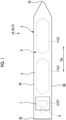
- a ship 1A serving as a floating structure includes at least a hull 2 serving as a floating main structure, a combustor 9, a first tank 11, a second tank 21, and a reliquefying/fuel supply system 30A (refer to Fig. 2 ).
- the hull 2 has a pair of broadsides 3A and 3B, a ship bottom (not illustrated), and an upper deck 5 which form an outer shell of the hull 2.
- the broadsides 3A and 3B have a pair of broadside outer plates respectively forming right and left broadsides.
- the ship bottom (not illustrated) has a ship bottom outer plate connecting the broadsides 3A and 3B.
- the pair of broadsides 3A and 3B and the ship bottom (not illustrated) cause the outer shell of the hull 2 to have a U-shape in a cross section orthogonal to a bow-stern direction Da.
- the upper deck 5 described as an example in this embodiment is a whole deck exposed outward.
- a superstructure 7 having an accommodation space is formed on the upper deck 5 on a stern 2b side. A position of the superstructure 7 is merely an example, and may be disposed on a bow 2a side of the hull 2, for example.
- a cargo tank storage compartment (hold) 8 for storing the first tank 11 is formed inside the hull 2.
- the combustor 9 is disposed inside the hull 2.
- the combustor 9 shows a required function by combusting a liquefied combustible gas F stored in the second tank 21.
- a main engine is an engine (internal combustion engine) that uses the liquefied combustible gas F as a fuel, and shows a propulsive force for propelling the hull 2.
- the generator includes an engine (internal combustion engine) that uses the liquefied combustible gas F as the fuel, and generates electric power used inside the hull 2 by using a driving force of the engine.
- the boiler combusts the liquefied combustible gas F to generate steam used inside the hull 2.
- the first tank 11 is disposed in the hull 2.
- the first tank 11 is disposed inside the cargo tank storage compartment 8.
- two first tanks 11 are disposed at an interval in the bow-stern direction Da.
- the first tank 11 has a cylindrical shape extending in a horizontal direction.
- the first tank 11 is not limited to the cylindrical shape, and the first tank 11 may have a spherical shape or a square shape.
- the first tank 11 can store carbon dioxide C having a gas phase and a liquid phase.
- the carbon dioxide C stored in the first tank 11 is a cargo (freight) of the ship 1A.
- the carbon dioxide C stored inside the first tank 11 is separated into the liquid phase and the gas phase inside the first tank 11.
- the liquid phase that is, the carbon dioxide C in a liquid state (hereinafter, referred to as a carbon dioxide liquid C1) is stored in a lower portion inside the first tank 11.
- the gas phase that is, the carbon dioxide C in a gas state (hereinafter, referred to as a carbon dioxide gas C2) is stored in an upper portion inside the first tank 11.
- the carbon dioxide gas C2 is a boil-off gas generated in such a manner that the carbon dioxide liquid C1 inside the first tank 11 is naturally vaporized by heat input from an outside.
- the first tank 11 includes a loading pipe 13 and an unloading pipe 14.
- the loading pipe 13 loads the carbon dioxide C (carbon dioxide liquid C1) supplied from an onshore facility into the first tank 11.
- the loading pipe 13 penetrates a top portion of the first tank 11 from the outside of the first tank 11, and extends to the inside of the first tank 11.
- a tip portion of the loading pipe 13 is open inside the first tank 11.
- Fig. 2 illustrates a case where the tip portion of the loading pipe 13 is located in the lower portion of the first tank 11.
- a disposition of the tip portion of the loading pipe 13 is not limited thereto (the same applies to a loading pipe of a second embodiment to be described later).
- the unloading pipe 14 feeds the carbon dioxide C (carbon dioxide liquid C1) inside the first tank 11 outboard.
- the unloading pipe 14 penetrates the top portion of the first tank 11 from the outside of the first tank 11, and extends to the inside of the first tank 11.
- An unloading pump 15 is provided in a tip portion of the unloading pipe 14.
- the unloading pump 15 suctions the carbon dioxide C (carbon dioxide liquid C1) inside the first tank 11.
- the unloading pipe 14 guides the carbon dioxide C (carbon dioxide liquid C1) delivered from the unloading pump 15 to the outside of the first tank 11 (outboard).
- the second tank 21 is disposed in the hull 2.
- the liquefied combustible gas F is stored in the second tank 21.
- the liquefied combustible gas F is a fuel in the ship 1A, and is combusted in the combustor 9. That is, the second tank 21 is a so-called fuel tank for storing the fuel.
- a temperature of the liquefied combustible gas F stored in the second tank 21 in a liquid state is lower than a temperature of the liquid phase of the carbon dioxide C stored in the first tank 11.
- the liquefied combustible gas F include a liquefied natural gas (LNG), methane, ethane, and hydrogen.
- LNG liquefied natural gas
- methane methane
- ethane hydrogen
- hydrogen hydrogen
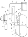
- the reliquefying/fuel supply system 30A reliquefies the carbon dioxide gas C2 stored inside the first tank 11. Furthermore, the reliquefying/fuel supply system 30A vaporizes the liquefied combustible gas F in a liquid state inside the second tank 21, and supplies the vaporized liquefied combustible gas F to the combustor 9.
- the reliquefying/fuel supply system 30A includes at least a first heat exchanger 31A and a second heat exchanger 32.
- the first heat exchanger 31A exchanges heat between the carbon dioxide gas C2 and the liquefied combustible gas F.
- Each of a feed line 33A, a return line 34A, a first fuel line 35, and a second fuel line 36 is connected to the first heat exchanger 31A.
- the feed line 33A guides the carbon dioxide gas C2 to the first heat exchanger 31A from the first tank 11.
- one end of the feed line 33A is connected to the top portion of the first tank 11.
- the feed line 33A guides the carbon dioxide gas C2 to the first heat exchanger 31A from the upper portion inside the first tank 11.
- a compressor 37 that compresses the carbon dioxide gas C2 is disposed in the feed line 33A.
- the return line 34A guides the carbon dioxide liquid C1 liquefied by the first heat exchanger 31A to the first tank 11 from the first heat exchanger 31A.
- the first fuel line 35 feeds the liquefied combustible gas F to the first heat exchanger 31A from the second tank 21 by using the fuel pump 25.
- the second fuel line 36 guides the liquefied combustible gas F to the second heat exchanger 32 from the first heat exchanger 31A.
- the second heat exchanger 32 vaporizes the liquefied combustible gas F by exchanging heat of the liquefied combustible gas F passing through the first heat exchanger 31A with a heat medium H.
- the liquefied natural gas is vaporized to be a natural gas.
- the heat medium H used in the second heat exchanger 32 include steam used inside the hull 2 and an exhaust gas from the combustor 9.
- a third fuel line 38 is connected to the second heat exchanger 32. The third fuel line 38 guides a gas obtained by vaporizing the liquefied combustible gas F to the combustor 9 from the second heat exchanger 32.
- the carbon dioxide gas C2 is fetched from the upper portion inside the first tank 11 by operating the compressor 37.
- the fetched carbon dioxide gas C2 is compressed by the compressor 37, and thereafter, is fed to the first heat exchanger 31A through the feed line 33A.
- the liquefied combustible gas F inside the second tank 21 is fed to the first heat exchanger 31A through the first fuel line 35 by the fuel pump 25. Then, in the first heat exchanger 31A, the heat is exchanged between the carbon dioxide gas C2 and the liquefied combustible gas F.
- the temperature of the liquefied combustible gas F in a liquid state is lower than the temperature of the carbon dioxide C. Therefore, the compressed carbon dioxide gas C2 is cooled and reliquefied by the heat exchange in the first heat exchanger 31A. The cooled and reliquefied carbon dioxide liquid C1 is returned to the first tank 11 through the return line 34A.
- the liquefied combustible gas F is heated by exchanging the heat with the carbon dioxide gas C2 having a higher temperature than the liquefied combustible gas F in the first heat exchanger 31A, and the temperature of the liquefied combustible gas F rises.
- the liquefied combustible gas F whose temperature is raised is fed to the second heat exchanger 32 through the second fuel line 36.
- the liquefied combustible gas F is further heated and vaporized by exchanging the heat with the heat medium H in the second heat exchanger 32.
- the vaporized liquefied combustible gas F is supplied to the combustor 9 through the third fuel line 38.
- the carbon dioxide gas C2 supplied to the first heat exchanger 31A from the first tank 11 through the feed line 33A is cooled and reliquefied by exchanging the heat with the liquefied combustible gas F in the first heat exchanger 31A.
- the reliquefied carbon dioxide liquid C1 is returned to the first tank 11 through the return line 34A.
- the temperature of the reliquefied carbon dioxide liquid C1 is lower than the temperature of the carbon dioxide C stored inside the first tank 11. Therefore, the cooled carbon dioxide liquid C1 is returned to the first tank 11 so that the temperature of the carbon dioxide C inside the first tank 11 is lowered. In this manner, a temperature rise inside the first tank 11 can be suppressed, and new vaporization of the carbon dioxide liquid C1 inside the first tank 11 can be suppressed.
- the temperature of the liquefied combustible gas F stored in the second tank 21 is raised by exchanging the heat with the carbon dioxide gas C2 in the first heat exchanger 31A, and thereafter, the liquefied combustible gas F is fed to the second heat exchanger 32. Therefore, in the second heat exchanger 32, the liquefied combustible gas F in a state of being heated in advance by the first heat exchanger 31A is vaporized by exchanging the heat with the heat medium H. Therefore, heat energy required for vaporizing the liquefied combustible gas F in the second heat exchanger 32 may be reduced, compared to a case where the first heat exchanger 31A is not provided.
- the carbon dioxide gas C2 has a higher temperature than the carbon dioxide liquid C1 cooled by latent heat of vaporization when the boil-off gas is generated. Therefore, in the first heat exchanger 31A, the temperature of the liquefied combustible gas F can be raised to a higher temperature, compared to a case of the heat exchange with the carbon dioxide liquid C1. In this regard, the heat energy required for vaporizing the liquefied combustible gas F in the second heat exchanger 32 is further reduced.
- the second embodiment described below is different from the first embodiment in only a configuration of a first heat exchanger 31B. Therefore, description will be made by assigning the same reference numerals to elements which are the same as those of the first embodiment, and repeated description will be omitted.
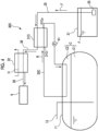
- a reliquefying/fuel supply system 30B of a ship 1B serving as a floating structure in the present embodiment includes the first heat exchanger 31B and the second heat exchanger 32.
- the first heat exchanger 31B exchanges the heat between the carbon dioxide C (carbon dioxide liquid C1) and the liquefied combustible gas F.
- a feed line 33B, a return line 34B, the first fuel line 35, and the second fuel line 36 are connected to the first heat exchanger 31B.
- the feed line 33B guides the carbon dioxide C to the first heat exchanger 31B from the first tank 11. More specifically, the feed line 33B guides the carbon dioxide liquid C1 to the first heat exchanger 31B from the lower portion in the first tank 11. The feed line 33B guides the carbon dioxide liquid C1 delivered from the unloading pump 15 to the first heat exchanger 31B.
- the feed line 33B is branched from the unloading pipe 14.
- On-off valves 39A and 39B are disposed in a portion where the feed line 33B and the unloading pipe 14 are branched.
- the on-off valve 39A opens and closes a flow path inside the unloading pipe 14.
- the on-off valve 39B opens and closes a flow path inside the feed line 33B.
- the on-off valve 39A is in a closed state, and the on-off valve 39B is in an open state.
- a small capacity pump may be installed separately from the unloading pump 15, and the carbon dioxide liquid C1 may be delivered to the feed line 33B by using the small capacity pump.
- the return line 34B guides the carbon dioxide liquid C1 to the first tank 11 from the first heat exchanger 31B.
- the return line 34B is connected to the top portion of the first tank 11.
- An injection unit 40 is disposed in the top portion of the first tank 11. The injection unit 40 injects the carbon dioxide liquid C1 returned to the first tank 11 from the first heat exchanger 31B through the return line 34B to the gas phase of the upper portion inside the first tank 11. Examples of this injection form include a shower-like form and a mist-like form.
- the injected carbon dioxide liquid C1 falls downward while coming into wide contact with the carbon dioxide gas C2 stored inside the first tank 11.
- the carbon dioxide liquid C1 is delivered from the lower portion inside the first tank 11 by operating the unloading pump 15.
- the delivered carbon dioxide liquid C1 is fed to the first heat exchanger 31B through the feed line 33B.
- the heat is exchanged between the carbon dioxide liquid C1 and the liquefied combustible gas F. Due to the heat exchange in the first heat exchanger 31B, the carbon dioxide liquid C1 is further cooled than the carbon dioxide liquid C1 inside the first tank 11, and is brought into a supercooled state.
- the carbon dioxide liquid C1 in the supercooled state is returned to the first tank 11 through the return line 34B.
- the carbon dioxide liquid C1 in the supercooled state is injected into the carbon dioxide gas C2 inside the first tank 11 by the injection unit 40.
- the carbon dioxide gas C2 stored in the upper portion inside the first tank 11 is cooled by the injected carbon dioxide liquid C1.
- at least a portion of the carbon dioxide gas C2 is reliquefied.
- the liquefied combustible gas F is heated by exchanging the heat with the carbon dioxide liquid C1 having a temperature higher than that of the liquefied combustible gas F in the first heat exchanger 31B, and the temperature of the liquefied combustible gas F rises.
- the liquefied combustible gas F whose temperature is raised is fed to the second heat exchanger 32 through the second fuel line 36.
- the liquefied combustible gas F is further heated and vaporized by exchanging the heat with the heat medium H in the second heat exchanger 32.
- the vaporized liquefied combustible gas F is supplied to the combustor 9 through the third fuel line 38.
- the carbon dioxide liquid C1 supplied from the first tank 11 through the feed line 33B is cooled by exchanging the heat with the liquefied combustible gas F in the first heat exchanger 31B.
- the cooled carbon dioxide liquid C1 is returned to the first tank 11 through the return line 34B. Since the cooled carbon dioxide liquid C1 is supplied into the first tank 11, the temperature of the carbon dioxide C inside the first tank 11 is lowered. In this manner, the temperature rise inside the first tank 11 can be suppressed, and new vaporization of the carbon dioxide liquid C1 can also be suppressed.
- the temperature of the liquefied combustible gas F stored in the second tank 21 is raised by exchanging the heat with the carbon dioxide C having a higher temperature than the liquefied combustible gas F in the first heat exchanger 31B, and thereafter, the liquefied combustible gas F is fed to the second heat exchanger 32. Therefore, in the second heat exchanger 32, the liquefied combustible gas F in a state of being heated in advance by the first heat exchanger 31B is vaporized by exchanging the heat with the heat medium H. Therefore, the heat energy required for vaporizing the liquefied combustible gas F in the second heat exchanger 32 may be reduced, compared to a case where the first heat exchanger 31B is not provided.
- the heat is exchanged between the carbon dioxide liquid C1 fetched from the inside of the first tank 11 and the liquefied combustible gas F.
- the carbon dioxide liquid C1 in the supercooled state is fed into the first tank 11. Therefore, the carbon dioxide gas C2 inside the first tank 11 can be cooled and reliquefied.
- the carbon dioxide liquid C1 is supplied to the first heat exchanger 31B from the first tank 11 by the unloading pump 15.
- the unloading pump 15 is provided to deliver the carbon dioxide liquid C1 inside the first tank 11 to the outside of the floating main structure 2 through the unloading pipe 14. In this way, the unloading pump 15 can also be used to reliquefy the carbon dioxide gas C2. Therefore, an increase in the number of components can be suppressed, and a cost increase can be suppressed.
- the carbon dioxide liquid C1 brought into the supercooled state by the heat exchange in the first heat exchanger 31B is injected into the upper portion inside the first tank 11 by the injection unit 40. Therefore, the carbon dioxide liquid C1 in the supercooled state can be brought into wider contact with the carbon dioxide gas C2 inside the first tank 11. Therefore, a larger amount of the carbon dioxide gas C2 can be reliquefied.
- a third embodiment of the floating structure according to the present invention will be described.
- the third embodiment described below is different from the first embodiment in that a target for exchanging the heat with the liquefied combustible gas F is a refrigerant. Therefore, Fig. 1 will be used as a reference, and description will be made by assigning the same reference numerals to elements which are the same as those of the first embodiment. Furthermore, detailed description of the elements which are the same as those of the first embodiment will be omitted.
- a reliquefying/fuel supply system 30C of a ship 1C serving as a floating structure in the present embodiment includes at least a first heat exchanger 31C, a second heat exchanger 32, a circulation line 33C, and a circulation pump 41.
- the first heat exchanger 31C exchanges the heat between a refrigerant R and the liquefied combustible gas F.
- the first fuel line 35, the second fuel line 36, and the circulation line 33C are connected to the first heat exchanger 31C.
- the circulation line 33C forms a flow path that circulates the refrigerant R between the inside of the first tank 11 and the first heat exchanger 31C.
- One end of the circulation line 33C is connected to a refrigerant outlet 31Co of the first heat exchanger 31C, and the other end of the circulation line 33C is connected to a refrigerant inlet 31Ci of the first heat exchanger 31C. Then, an intermediate portion of the circulation line 33C passes through the inside of the first tank 11.
- the circulation line 33C in the third embodiment passes through the gas phase inside the first tank 11.
- a portion of the circulation line 33C which passes through at least the first tank 11 can be formed of a material having high thermal conductivity such as metal, a material having a large heat transfer area such as a fin tube, and a combination thereof.
- a portion of the circulation line 33C which is disposed outside the first tank 11 may be formed of a material having high heat insulating performance, or may be covered with a heat insulating material.
- refrigerant R a refrigerant having a boiling point of approximately -40°C can be used.
- the portion passing through the inside of the first tank 11 passes through only the gas phase.
- the portion passing through the inside of the first tank 11 is not limited to a case of passing through only the gas phase.
- some of the portion passing through the inside of the first tank 11 may be in contact with the liquid phase.
- the portion passing through the inside of the first tank 11 may be submerged in the liquid phase when a liquid level inside the first tank 11 rises.
- the circulation pump 41 is installed in an intermediate portion of the circulation line 33C.
- the circulation pump 41 of the present embodiment is disposed between an outlet 31Co of the first heat exchanger 31C and the first tank 11 in the circulation line 33C.
- the circulation pump 41 delivers the refrigerant R inside the circulation line 33C from one end to the other end of the circulation line 33C.
- the circulation pump 41 is operated so that the refrigerant R discharged from the outlet 31Co of the first heat exchanger 31C flows toward the first tank 11 through a flow path inside the circulation line 33C. Then, the refrigerant R flows through the flow path of the circulation line 33C disposed inside the first tank 11. In this case, the refrigerant R exchanges the heat with the carbon dioxide C (at least one of the carbon dioxide gas C2 and the carbon dioxide liquid C1) inside the first tank 11, and the temperature of the refrigerant R rises.
- the carbon dioxide C at least one of the carbon dioxide gas C2 and the carbon dioxide liquid C1
- the refrigerant R flows through the flow path of the circulation line 33C disposed outside the first tank 11, and thereafter, reaches the refrigerant inlet 31Ci of the first heat exchanger 31C. Then, the refrigerant R exchanges the heat with the liquefied combustible gas F in the first heat exchanger 31C to lower the temperature, and is discharged again from the refrigerant outlet 31Co. In this way, the refrigerant R is circulated inside the circulation line 33C.
- the circulation pump 41 may be operated only when a pressure inside the first tank 11 rises above a threshold value. Alternatively, the circulation pump 41 may be always operated when the combustor 9 is operated.
- the liquefied combustible gas F which is heated by exchanging the heat with the refrigerant R having a temperature higher than that of the liquefied combustible gas F in the first heat exchanger 31B and whose temperature is raised is fed to the second heat exchanger 32 through the second fuel line 36 as in the first embodiment.
- the liquefied combustible gas F is further heated and vaporized by exchanging the heat with the heat medium H in the second heat exchanger 32.
- the vaporized liquefied combustible gas F is supplied to the combustor 9 through the third fuel line 38.
- the temperature of the carbon dioxide C inside the first tank 11 exchanging the heat with the refrigerant R is lowered.
- the temperature of the carbon dioxide gas C2 is lowered by directly exchanging the heat with the refrigerant R or by coming into contact with the carbon dioxide liquid C1 whose heat is exchanged with the refrigerant R.
- a volume of the carbon dioxide gas C2 is reduced in the gas state, or the carbon dioxide gas C2 is liquefied. In this manner, a pressure increase inside the first tank 11 is suppressed.
- the ship 1C of the above-described third embodiment includes the hull 2, the first tank 11 disposed in the hull 2 and storing the carbon dioxide C having the gas phase and the liquid phase, the second tank 21 disposed in the hull 2 and capable of storing the liquefied combustible gas F whose temperature in the liquid state is lower than the temperature of the liquid phase of the carbon dioxide C, the first heat exchanger 31C that exchanges the heat between the liquefied combustible gas F and the refrigerant R, the circulation line 33C that circulates the refrigerant R between the inside of the first tank 11 and the first heat exchanger 31C, the circulation pump 41 provided in the intermediate portion of the circulation line 33C and circulate the refrigerant R, the second heat exchanger 32 that vaporizes the liquefied combustible gas F passing through the first heat exchanger 31C by exchanging the heat with the heat medium H, and the combustor 9 that combusts the liquefied combustible gas F vaporized
- the heat can be exchanged between the carbon dioxide C inside the first tank 11 and the liquefied combustible gas F via the refrigerant R. Therefore, the carbon dioxide gas C2 or the carbon dioxide liquid C1 does not need to flow into a pipe outside the first tank 11. Therefore, the heat input to the carbon dioxide C can be suppressed, and the pressure inside the first tank 11 can be efficiently reduced.
- the circulation line 33C passes through at least the liquid phase of the first tank 11.
- the temperature of the carbon dioxide gas C2 inside the first tank 11 whose heat is exchanged with the refrigerant R can be lowered.
- a volume of the carbon dioxide gas C2 can be reduced in the gas state, or the carbon dioxide gas C2 can be liquefied. Therefore, a pressure increase inside the first tank 11 can be efficiently suppressed.
- first tanks 11 a configuration including two first tanks 11 has been adopted.
- the configuration may include one, three, or more first tanks 11.
- a case where the plurality of first tanks 11 are aligned in the bow-stern direction Da has been described as an example.
- the first tanks 11 may be aligned in a ship width direction (in other words, a right-left broadside direction).
- the ships 1A and 1B have been described as examples of the floating structure.
- the floating structure may be an offshore floating structure facility which does not include a propulsion mechanism.
- the flow path of the refrigerant R may meander in the portion disposed inside the first tank 11.
- the refrigerant R is circulated in the liquid state.
- an expansion valve 42 and a compressor 43 is provided to construct a refrigerating cycle in the intermediate portion of the circulation line 33C.
- the expansion valve 42 may be provided between the refrigerant outlet 31Co of the first heat exchanger 31C and the first tank 11, and the compressor 43 may be provided between the first tank 11 and the refrigerant inlet 31Ci of the first heat exchanger 31C.
- the liquefied carbon dioxide vaporized inside the tank can be efficiently cooled and reliquefied while energy is effectively utilized.
Landscapes
- Engineering & Computer Science (AREA)
- Mechanical Engineering (AREA)
- General Engineering & Computer Science (AREA)
- Physics & Mathematics (AREA)
- Thermal Sciences (AREA)
- Chemical & Material Sciences (AREA)
- Ocean & Marine Engineering (AREA)
- Combustion & Propulsion (AREA)
- Chemical Kinetics & Catalysis (AREA)
- Filling Or Discharging Of Gas Storage Vessels (AREA)
- Artificial Filaments (AREA)
Description
- The present disclosure relates to a floating structure.
- Priority is claimed on
Japanese Patent Application No. 2020-182076, filed October 30, 2020 Japanese Patent Application No. 2021-061657 filed March 31, 2021 - In a floating structure such as a ship including a tank for storing a liquefied gas, the liquefied gas stored inside the tank is vaporized due to heat input from an outside, and so-called a boil-off gas is generated. When the boil-off gas is generated, a pressure inside the tank rises. Therefore, for example, PTL 1 discloses a configuration as follows. In order to reliquefy a fuel boil-off gas generated from a liquefied gas fuel stored in a fuel tank, the fuel boil-off gas is cooled by cold heat of the boil-off gas of the liquefied gas generated in a cargo tank. Document PTL 2 discloses the preamble of independent claim 1.
-
- [PTL 1]
Japanese Unexamined Patent Application Publication No. 2018-127137 - [PTL 2] YOO BYEONG-YONG ED - NITU PUICA ET AL, "The development and comparison of CO2BOG re-liquefaction processes for LNG fueled CO2carriers", ENERGY, ELSEVIER, AMSTERDAM, NL, (20170321), vol. 127, doi:10.1016/J.ENERGY.2017.03.073, ISSN 0360-5442, pages 186 - 197, XP085025604 [X] 1,3 * abstract * * paragraph [02.2];
figures 3 ,6. - [PTL 3]
KR101319364B1 - Incidentally, when liquefied carbon dioxide is stored in a tank, the liquefied carbon dioxide is liquefied to recover carbon dioxide released into an atmosphere in the first place. Therefore, it is desirable that energy required for reliquefying carbon dioxide gas generated by vaporizing the liquefied carbon dioxide inside the tank is suppressed as much as possible. From a viewpoint of suppressing the energy required for reliquefication, it is conceivable to release the carbon dioxide gas into the atmosphere. However, as a matter of course, it is not preferable to release the recovered carbon dioxide into the atmosphere.
- The present invention is made to solve the above-described problem, and an object of the present invention is to provide a floating structure which can efficiently cool and reliquefy liquefied carbon dioxide vaporized inside a tank while effectively utilizing energy.
- According to the present invention, in order to solve the above-described problem, there is provided a floating structure according to claim 1.
- According to the floating structure of the present invention, the liquefied carbon dioxide vaporized inside the tank can be efficiently cooled and reliquefied while energy is effectively utilized.
-
-
Fig. 1 is a plan view illustrating a schematic configuration of a ship serving as a floating structure according to an embodiment which does not form part of the invention. -
Fig. 2 is a view illustrating a schematic configuration of a reliquefying/fuel supply system provided in a ship according to a first embodiment which does not form part of the invention. -
Fig. 3 is a view illustrating a schematic configuration of a reliquefying/fuel supply system provided in a ship according to a second embodiment which does not form part of the invention. -
Fig. 4 is a view illustrating a schematic configuration of a reliquefying/fuel supply system provided in a ship according to a third embodiment which does not form part of the invention. -
Fig. 5 is a view illustrating a schematic configuration of a reliquefying/fuel supply system provided in a ship according to the invention. - Hereinafter, a floating structure according to an embodiment of the present disclosure will be described with reference to
Figs. 1 to 3 . - As illustrated in
Fig. 1 , in this embodiment, aship 1A serving as a floating structure includes at least a hull 2 serving as a floating main structure, acombustor 9, afirst tank 11, asecond tank 21, and a reliquefying/fuel supply system 30A (refer toFig. 2 ). - The hull 2 has a pair of
broadsides upper deck 5 which form an outer shell of the hull 2. Thebroadsides broadsides broadsides upper deck 5 described as an example in this embodiment is a whole deck exposed outward. In the hull 2, a superstructure 7 having an accommodation space is formed on theupper deck 5 on astern 2b side. A position of the superstructure 7 is merely an example, and may be disposed on abow 2a side of the hull 2, for example. - A cargo tank storage compartment (hold) 8 for storing the
first tank 11 is formed inside the hull 2. - The
combustor 9 is disposed inside the hull 2. Thecombustor 9 shows a required function by combusting a liquefied combustible gas F stored in thesecond tank 21. For example, as thecombustor 9, a main engine, a generator, and a boiler may be adopted. The main engine is an engine (internal combustion engine) that uses the liquefied combustible gas F as a fuel, and shows a propulsive force for propelling the hull 2. The generator includes an engine (internal combustion engine) that uses the liquefied combustible gas F as the fuel, and generates electric power used inside the hull 2 by using a driving force of the engine. The boiler combusts the liquefied combustible gas F to generate steam used inside the hull 2. - The
first tank 11 is disposed in the hull 2. Thefirst tank 11 is disposed inside the cargo tank storage compartment 8. In this embodiment, twofirst tanks 11 are disposed at an interval in the bow-stern direction Da. In the present embodiment, for example, thefirst tank 11 has a cylindrical shape extending in a horizontal direction. Thefirst tank 11 is not limited to the cylindrical shape, and thefirst tank 11 may have a spherical shape or a square shape. - The
first tank 11 can store carbon dioxide C having a gas phase and a liquid phase. The carbon dioxide C stored in thefirst tank 11 is a cargo (freight) of theship 1A. - As illustrated in
Fig. 2 , the carbon dioxide C stored inside thefirst tank 11 is separated into the liquid phase and the gas phase inside thefirst tank 11. The liquid phase, that is, the carbon dioxide C in a liquid state (hereinafter, referred to as a carbon dioxide liquid C1) is stored in a lower portion inside thefirst tank 11. The gas phase, that is, the carbon dioxide C in a gas state (hereinafter, referred to as a carbon dioxide gas C2) is stored in an upper portion inside thefirst tank 11. The carbon dioxide gas C2 is a boil-off gas generated in such a manner that the carbon dioxide liquid C1 inside thefirst tank 11 is naturally vaporized by heat input from an outside. - The
first tank 11 includes aloading pipe 13 and anunloading pipe 14. - The
loading pipe 13 loads the carbon dioxide C (carbon dioxide liquid C1) supplied from an onshore facility into thefirst tank 11. Theloading pipe 13 penetrates a top portion of thefirst tank 11 from the outside of thefirst tank 11, and extends to the inside of thefirst tank 11. A tip portion of theloading pipe 13 is open inside thefirst tank 11.Fig. 2 illustrates a case where the tip portion of theloading pipe 13 is located in the lower portion of thefirst tank 11. However, a disposition of the tip portion of theloading pipe 13 is not limited thereto (the same applies to a loading pipe of a second embodiment to be described later). - The unloading
pipe 14 feeds the carbon dioxide C (carbon dioxide liquid C1) inside thefirst tank 11 outboard. The unloadingpipe 14 penetrates the top portion of thefirst tank 11 from the outside of thefirst tank 11, and extends to the inside of thefirst tank 11. An unloadingpump 15 is provided in a tip portion of the unloadingpipe 14. The unloadingpump 15 suctions the carbon dioxide C (carbon dioxide liquid C1) inside thefirst tank 11. The unloadingpipe 14 guides the carbon dioxide C (carbon dioxide liquid C1) delivered from the unloadingpump 15 to the outside of the first tank 11 (outboard). - The
second tank 21 is disposed in the hull 2. The liquefied combustible gas F is stored in thesecond tank 21. The liquefied combustible gas F is a fuel in theship 1A, and is combusted in thecombustor 9. That is, thesecond tank 21 is a so-called fuel tank for storing the fuel. - A temperature of the liquefied combustible gas F stored in the
second tank 21 in a liquid state is lower than a temperature of the liquid phase of the carbon dioxide C stored in thefirst tank 11. Examples of the liquefied combustible gas F include a liquefied natural gas (LNG), methane, ethane, and hydrogen. In the present embodiment, a case where the liquefied natural gas is used as the liquefied combustible gas F will be described as an example. - The reliquefying/
fuel supply system 30A reliquefies the carbon dioxide gas C2 stored inside thefirst tank 11. Furthermore, the reliquefying/fuel supply system 30A vaporizes the liquefied combustible gas F in a liquid state inside thesecond tank 21, and supplies the vaporized liquefied combustible gas F to thecombustor 9. The reliquefying/fuel supply system 30A includes at least afirst heat exchanger 31A and asecond heat exchanger 32. - The
first heat exchanger 31A exchanges heat between the carbon dioxide gas C2 and the liquefied combustible gas F. Each of afeed line 33A, areturn line 34A, afirst fuel line 35, and asecond fuel line 36 is connected to thefirst heat exchanger 31A. - The
feed line 33A guides the carbon dioxide gas C2 to thefirst heat exchanger 31A from thefirst tank 11. In the present embodiment, one end of thefeed line 33A is connected to the top portion of thefirst tank 11. Thefeed line 33A guides the carbon dioxide gas C2 to thefirst heat exchanger 31A from the upper portion inside thefirst tank 11. Acompressor 37 that compresses the carbon dioxide gas C2 is disposed in thefeed line 33A. - The
return line 34A guides the carbon dioxide liquid C1 liquefied by thefirst heat exchanger 31A to thefirst tank 11 from thefirst heat exchanger 31A. - The
first fuel line 35 feeds the liquefied combustible gas F to thefirst heat exchanger 31A from thesecond tank 21 by using thefuel pump 25. Thesecond fuel line 36 guides the liquefied combustible gas F to thesecond heat exchanger 32 from thefirst heat exchanger 31A. - The
second heat exchanger 32 vaporizes the liquefied combustible gas F by exchanging heat of the liquefied combustible gas F passing through thefirst heat exchanger 31A with a heat medium H. In thesecond heat exchanger 32 in this embodiment, the liquefied natural gas is vaporized to be a natural gas. Examples of the heat medium H used in thesecond heat exchanger 32 include steam used inside the hull 2 and an exhaust gas from thecombustor 9. A third fuel line 38 is connected to thesecond heat exchanger 32. The third fuel line 38 guides a gas obtained by vaporizing the liquefied combustible gas F to thecombustor 9 from thesecond heat exchanger 32. - In the reliquefying/
fuel supply system 30A configured in this way, the carbon dioxide gas C2 is fetched from the upper portion inside thefirst tank 11 by operating thecompressor 37. The fetched carbon dioxide gas C2 is compressed by thecompressor 37, and thereafter, is fed to thefirst heat exchanger 31A through thefeed line 33A. On the other hand, the liquefied combustible gas F inside thesecond tank 21 is fed to thefirst heat exchanger 31A through thefirst fuel line 35 by thefuel pump 25. Then, in thefirst heat exchanger 31A, the heat is exchanged between the carbon dioxide gas C2 and the liquefied combustible gas F. - The temperature of the liquefied combustible gas F in a liquid state is lower than the temperature of the carbon dioxide C. Therefore, the compressed carbon dioxide gas C2 is cooled and reliquefied by the heat exchange in the
first heat exchanger 31A. The cooled and reliquefied carbon dioxide liquid C1 is returned to thefirst tank 11 through thereturn line 34A. - In addition, the liquefied combustible gas F is heated by exchanging the heat with the carbon dioxide gas C2 having a higher temperature than the liquefied combustible gas F in the
first heat exchanger 31A, and the temperature of the liquefied combustible gas F rises. The liquefied combustible gas F whose temperature is raised is fed to thesecond heat exchanger 32 through thesecond fuel line 36. The liquefied combustible gas F is further heated and vaporized by exchanging the heat with the heat medium H in thesecond heat exchanger 32. The vaporized liquefied combustible gas F is supplied to thecombustor 9 through the third fuel line 38. - In the
ship 1A of the above-described embodiment, the carbon dioxide gas C2 supplied to thefirst heat exchanger 31A from thefirst tank 11 through thefeed line 33A is cooled and reliquefied by exchanging the heat with the liquefied combustible gas F in thefirst heat exchanger 31A. The reliquefied carbon dioxide liquid C1 is returned to thefirst tank 11 through thereturn line 34A. The temperature of the reliquefied carbon dioxide liquid C1 is lower than the temperature of the carbon dioxide C stored inside thefirst tank 11. Therefore, the cooled carbon dioxide liquid C1 is returned to thefirst tank 11 so that the temperature of the carbon dioxide C inside thefirst tank 11 is lowered. In this manner, a temperature rise inside thefirst tank 11 can be suppressed, and new vaporization of the carbon dioxide liquid C1 inside thefirst tank 11 can be suppressed. - On the other hand, the temperature of the liquefied combustible gas F stored in the
second tank 21 is raised by exchanging the heat with the carbon dioxide gas C2 in thefirst heat exchanger 31A, and thereafter, the liquefied combustible gas F is fed to thesecond heat exchanger 32. Therefore, in thesecond heat exchanger 32, the liquefied combustible gas F in a state of being heated in advance by thefirst heat exchanger 31A is vaporized by exchanging the heat with the heat medium H. Therefore, heat energy required for vaporizing the liquefied combustible gas F in thesecond heat exchanger 32 may be reduced, compared to a case where thefirst heat exchanger 31A is not provided. - In this way, the carbon dioxide gas C2 generated inside the
first tank 11 can be efficiently reliquefied the energy is effectively utilized. - In addition, the carbon dioxide gas C2 has a higher temperature than the carbon dioxide liquid C1 cooled by latent heat of vaporization when the boil-off gas is generated. Therefore, in the
first heat exchanger 31A, the temperature of the liquefied combustible gas F can be raised to a higher temperature, compared to a case of the heat exchange with the carbon dioxide liquid C1. In this regard, the heat energy required for vaporizing the liquefied combustible gas F in thesecond heat exchanger 32 is further reduced. - Next, a second embodiment of the floating structure according to the present invention will be described. The second embodiment described below is different from the first embodiment in only a configuration of a
first heat exchanger 31B. Therefore, description will be made by assigning the same reference numerals to elements which are the same as those of the first embodiment, and repeated description will be omitted. - As illustrated in
Fig. 3 , a reliquefying/fuel supply system 30B of aship 1B serving as a floating structure in the present embodiment includes thefirst heat exchanger 31B and thesecond heat exchanger 32. - The
first heat exchanger 31B exchanges the heat between the carbon dioxide C (carbon dioxide liquid C1) and the liquefied combustible gas F. Afeed line 33B, areturn line 34B, thefirst fuel line 35, and thesecond fuel line 36 are connected to thefirst heat exchanger 31B. - The
feed line 33B guides the carbon dioxide C to thefirst heat exchanger 31B from thefirst tank 11. More specifically, thefeed line 33B guides the carbon dioxide liquid C1 to thefirst heat exchanger 31B from the lower portion in thefirst tank 11. Thefeed line 33B guides the carbon dioxide liquid C1 delivered from the unloadingpump 15 to thefirst heat exchanger 31B. Thefeed line 33B is branched from the unloadingpipe 14. On-offvalves feed line 33B and the unloadingpipe 14 are branched. The on-offvalve 39A opens and closes a flow path inside the unloadingpipe 14. The on-offvalve 39B opens and closes a flow path inside thefeed line 33B. For example, when the carbon dioxide liquid C1 inside thefirst tank 11 is fed to thefirst heat exchanger 31B by the unloadingpump 15, the on-offvalve 39A is in a closed state, and the on-offvalve 39B is in an open state. A case has been described where the carbon dioxide liquid C1 is delivered to thefeed line 33B by the unloadingpump 15. However, a small capacity pump may be installed separately from the unloadingpump 15, and the carbon dioxide liquid C1 may be delivered to thefeed line 33B by using the small capacity pump. - The
return line 34B guides the carbon dioxide liquid C1 to thefirst tank 11 from thefirst heat exchanger 31B. In the present embodiment, thereturn line 34B is connected to the top portion of thefirst tank 11. Aninjection unit 40 is disposed in the top portion of thefirst tank 11. Theinjection unit 40 injects the carbon dioxide liquid C1 returned to thefirst tank 11 from thefirst heat exchanger 31B through thereturn line 34B to the gas phase of the upper portion inside thefirst tank 11. Examples of this injection form include a shower-like form and a mist-like form. The injected carbon dioxide liquid C1 falls downward while coming into wide contact with the carbon dioxide gas C2 stored inside thefirst tank 11. - In the reliquefying/
fuel supply system 30B configured in this way, the carbon dioxide liquid C1 is delivered from the lower portion inside thefirst tank 11 by operating the unloadingpump 15. The delivered carbon dioxide liquid C1 is fed to thefirst heat exchanger 31B through thefeed line 33B. In thefirst heat exchanger 31B, the heat is exchanged between the carbon dioxide liquid C1 and the liquefied combustible gas F. Due to the heat exchange in thefirst heat exchanger 31B, the carbon dioxide liquid C1 is further cooled than the carbon dioxide liquid C1 inside thefirst tank 11, and is brought into a supercooled state. The carbon dioxide liquid C1 in the supercooled state is returned to thefirst tank 11 through thereturn line 34B. - The carbon dioxide liquid C1 in the supercooled state is injected into the carbon dioxide gas C2 inside the
first tank 11 by theinjection unit 40. In this manner, the carbon dioxide gas C2 stored in the upper portion inside thefirst tank 11 is cooled by the injected carbon dioxide liquid C1. In this manner, at least a portion of the carbon dioxide gas C2 is reliquefied. - On the other hand, the liquefied combustible gas F is heated by exchanging the heat with the carbon dioxide liquid C1 having a temperature higher than that of the liquefied combustible gas F in the
first heat exchanger 31B, and the temperature of the liquefied combustible gas F rises. The liquefied combustible gas F whose temperature is raised is fed to thesecond heat exchanger 32 through thesecond fuel line 36. The liquefied combustible gas F is further heated and vaporized by exchanging the heat with the heat medium H in thesecond heat exchanger 32. The vaporized liquefied combustible gas F is supplied to thecombustor 9 through the third fuel line 38. - In the
ship 1B of the above-described second embodiment, the carbon dioxide liquid C1 supplied from thefirst tank 11 through thefeed line 33B is cooled by exchanging the heat with the liquefied combustible gas F in thefirst heat exchanger 31B. The cooled carbon dioxide liquid C1 is returned to thefirst tank 11 through thereturn line 34B. Since the cooled carbon dioxide liquid C1 is supplied into thefirst tank 11, the temperature of the carbon dioxide C inside thefirst tank 11 is lowered. In this manner, the temperature rise inside thefirst tank 11 can be suppressed, and new vaporization of the carbon dioxide liquid C1 can also be suppressed. - Furthermore, the temperature of the liquefied combustible gas F stored in the
second tank 21 is raised by exchanging the heat with the carbon dioxide C having a higher temperature than the liquefied combustible gas F in thefirst heat exchanger 31B, and thereafter, the liquefied combustible gas F is fed to thesecond heat exchanger 32. Therefore, in thesecond heat exchanger 32, the liquefied combustible gas F in a state of being heated in advance by thefirst heat exchanger 31B is vaporized by exchanging the heat with the heat medium H. Therefore, the heat energy required for vaporizing the liquefied combustible gas F in thesecond heat exchanger 32 may be reduced, compared to a case where thefirst heat exchanger 31B is not provided. - In this way, the carbon dioxide gas C2 generated inside the
first tank 11 can be efficiently reliquefied the energy is effectively utilized. - In addition, in the
first heat exchanger 31B of the second embodiment, the heat is exchanged between the carbon dioxide liquid C1 fetched from the inside of thefirst tank 11 and the liquefied combustible gas F. In this manner, the carbon dioxide liquid C1 in the supercooled state is fed into thefirst tank 11. Therefore, the carbon dioxide gas C2 inside thefirst tank 11 can be cooled and reliquefied. - In addition, in the
ship 1B of the second embodiment, the carbon dioxide liquid C1 is supplied to thefirst heat exchanger 31B from thefirst tank 11 by the unloadingpump 15. The unloadingpump 15 is provided to deliver the carbon dioxide liquid C1 inside thefirst tank 11 to the outside of the floating main structure 2 through the unloadingpipe 14. In this way, the unloadingpump 15 can also be used to reliquefy the carbon dioxide gas C2. Therefore, an increase in the number of components can be suppressed, and a cost increase can be suppressed. - In addition, in the
ship 1B of the second embodiment, the carbon dioxide liquid C1 brought into the supercooled state by the heat exchange in thefirst heat exchanger 31B is injected into the upper portion inside thefirst tank 11 by theinjection unit 40. Therefore, the carbon dioxide liquid C1 in the supercooled state can be brought into wider contact with the carbon dioxide gas C2 inside thefirst tank 11. Therefore, a larger amount of the carbon dioxide gas C2 can be reliquefied. - Next, a third embodiment of the floating structure according to the present invention will be described. The third embodiment described below is different from the first embodiment in that a target for exchanging the heat with the liquefied combustible gas F is a refrigerant. Therefore,
Fig. 1 will be used as a reference, and description will be made by assigning the same reference numerals to elements which are the same as those of the first embodiment. Furthermore, detailed description of the elements which are the same as those of the first embodiment will be omitted. - As illustrated in
Fig. 4 , a reliquefying/fuel supply system 30C of aship 1C serving as a floating structure in the present embodiment includes at least afirst heat exchanger 31C, asecond heat exchanger 32, acirculation line 33C, and acirculation pump 41. - The
first heat exchanger 31C exchanges the heat between a refrigerant R and the liquefied combustible gas F. Thefirst fuel line 35, thesecond fuel line 36, and thecirculation line 33C are connected to thefirst heat exchanger 31C. - The
circulation line 33C forms a flow path that circulates the refrigerant R between the inside of thefirst tank 11 and thefirst heat exchanger 31C. One end of thecirculation line 33C is connected to a refrigerant outlet 31Co of thefirst heat exchanger 31C, and the other end of thecirculation line 33C is connected to a refrigerant inlet 31Ci of thefirst heat exchanger 31C. Then, an intermediate portion of thecirculation line 33C passes through the inside of thefirst tank 11. Thecirculation line 33C in the third embodiment passes through the gas phase inside thefirst tank 11. In the third embodiment, a portion of thecirculation line 33C which passes through at least the first tank 11 (hereinafter, referred to as a portion passing through the inside of the first tank 11) can be formed of a material having high thermal conductivity such as metal, a material having a large heat transfer area such as a fin tube, and a combination thereof. In addition, a portion of thecirculation line 33C which is disposed outside the first tank 11 (particularly, a portion between the refrigerant outlet 31Co and the first tank 11) may be formed of a material having high heat insulating performance, or may be covered with a heat insulating material. As the above-described refrigerant R, a refrigerant having a boiling point of approximately -40°C can be used. A case has been described where the portion passing through the inside of thefirst tank 11 passes through only the gas phase. However, the portion passing through the inside of thefirst tank 11 is not limited to a case of passing through only the gas phase. For example, some of the portion passing through the inside of thefirst tank 11 may be in contact with the liquid phase. In addition, without being limited to a configuration in which the portion passing through the inside of thefirst tank 11 is always in contact with the gas phase, for example, the portion passing through the inside of thefirst tank 11 may be submerged in the liquid phase when a liquid level inside thefirst tank 11 rises. - The
circulation pump 41 is installed in an intermediate portion of thecirculation line 33C. Thecirculation pump 41 of the present embodiment is disposed between an outlet 31Co of thefirst heat exchanger 31C and thefirst tank 11 in thecirculation line 33C. Thecirculation pump 41 delivers the refrigerant R inside thecirculation line 33C from one end to the other end of thecirculation line 33C. - In the reliquefying/
fuel supply system 30C configured in this way, thecirculation pump 41 is operated so that the refrigerant R discharged from the outlet 31Co of thefirst heat exchanger 31C flows toward thefirst tank 11 through a flow path inside thecirculation line 33C. Then, the refrigerant R flows through the flow path of thecirculation line 33C disposed inside thefirst tank 11. In this case, the refrigerant R exchanges the heat with the carbon dioxide C (at least one of the carbon dioxide gas C2 and the carbon dioxide liquid C1) inside thefirst tank 11, and the temperature of the refrigerant R rises. - Thereafter, the refrigerant R flows through the flow path of the
circulation line 33C disposed outside thefirst tank 11, and thereafter, reaches the refrigerant inlet 31Ci of thefirst heat exchanger 31C. Then, the refrigerant R exchanges the heat with the liquefied combustible gas F in thefirst heat exchanger 31C to lower the temperature, and is discharged again from the refrigerant outlet 31Co. In this way, the refrigerant R is circulated inside thecirculation line 33C. As a timing at which thecirculation pump 41 is operated in the third embodiment, thecirculation pump 41 may be operated only when a pressure inside thefirst tank 11 rises above a threshold value. Alternatively, thecirculation pump 41 may be always operated when thecombustor 9 is operated. - The liquefied combustible gas F which is heated by exchanging the heat with the refrigerant R having a temperature higher than that of the liquefied combustible gas F in the
first heat exchanger 31B and whose temperature is raised is fed to thesecond heat exchanger 32 through thesecond fuel line 36 as in the first embodiment. The liquefied combustible gas F is further heated and vaporized by exchanging the heat with the heat medium H in thesecond heat exchanger 32. The vaporized liquefied combustible gas F is supplied to thecombustor 9 through the third fuel line 38. - In addition, the temperature of the carbon dioxide C inside the
first tank 11 exchanging the heat with the refrigerant R is lowered. In this case, the temperature of the carbon dioxide gas C2 is lowered by directly exchanging the heat with the refrigerant R or by coming into contact with the carbon dioxide liquid C1 whose heat is exchanged with the refrigerant R. In this manner, a volume of the carbon dioxide gas C2 is reduced in the gas state, or the carbon dioxide gas C2 is liquefied. In this manner, a pressure increase inside thefirst tank 11 is suppressed. - The
ship 1C of the above-described third embodiment includes the hull 2, thefirst tank 11 disposed in the hull 2 and storing the carbon dioxide C having the gas phase and the liquid phase, thesecond tank 21 disposed in the hull 2 and capable of storing the liquefied combustible gas F whose temperature in the liquid state is lower than the temperature of the liquid phase of the carbon dioxide C, thefirst heat exchanger 31C that exchanges the heat between the liquefied combustible gas F and the refrigerant R, thecirculation line 33C that circulates the refrigerant R between the inside of thefirst tank 11 and thefirst heat exchanger 31C, thecirculation pump 41 provided in the intermediate portion of thecirculation line 33C and circulate the refrigerant R, thesecond heat exchanger 32 that vaporizes the liquefied combustible gas F passing through thefirst heat exchanger 31C by exchanging the heat with the heat medium H, and thecombustor 9 that combusts the liquefied combustible gas F vaporized by thesecond heat exchanger 32. - According to the third embodiment, in addition to the operational effect of the first embodiment, the heat can be exchanged between the carbon dioxide C inside the
first tank 11 and the liquefied combustible gas F via the refrigerant R. Therefore, the carbon dioxide gas C2 or the carbon dioxide liquid C1 does not need to flow into a pipe outside thefirst tank 11. Therefore, the heat input to the carbon dioxide C can be suppressed, and the pressure inside thefirst tank 11 can be efficiently reduced. - In addition, in the
ship 1C of the above-described third embodiment, thecirculation line 33C passes through at least the liquid phase of thefirst tank 11. - According to this configuration, the temperature of the carbon dioxide gas C2 inside the
first tank 11 whose heat is exchanged with the refrigerant R can be lowered. In this manner, a volume of the carbon dioxide gas C2 can be reduced in the gas state, or the carbon dioxide gas C2 can be liquefied. Therefore, a pressure increase inside thefirst tank 11 can be efficiently suppressed. - In the above-described embodiment, a configuration including two
first tanks 11 has been adopted. However, the present disclosure is not limited thereto. The configuration may include one, three, or morefirst tanks 11. In addition, in the above-described embodiment, a case where the plurality offirst tanks 11 are aligned in the bow-stern direction Da has been described as an example. However, thefirst tanks 11 may be aligned in a ship width direction (in other words, a right-left broadside direction). - In addition, in the above-described embodiment, the
ships - In addition, in the above-described third embodiment, a case has been described where the heat is exchanged between the refrigerant R and the carbon dioxide C by utilizing the heat conduction of the pipe of the
circulation line 33C. However, another heat exchanger that exchanges the heat between the refrigerant R and the carbon dioxide C may be provided in the intermediate portion of thecirculation line 33C inside thefirst tank 11. - In addition, in the
circulation line 33C in the above-described third embodiment, the flow path of the refrigerant R may meander in the portion disposed inside thefirst tank 11. - In addition, in the above-described third embodiment, a case has been described where the refrigerant R is circulated in the liquid state. However, according to the invention, as illustrated in
Fig. 5 , instead of the above-describedcirculation pump 41, anexpansion valve 42 and acompressor 43 is provided to construct a refrigerating cycle in the intermediate portion of thecirculation line 33C. In this case, theexpansion valve 42 may be provided between the refrigerant outlet 31Co of thefirst heat exchanger 31C and thefirst tank 11, and thecompressor 43 may be provided between thefirst tank 11 and the refrigerant inlet 31Ci of thefirst heat exchanger 31C. When a refrigerating cycle is constructed in this way, capacity to cool the carbon dioxide gas C2 can be improved. Therefore, for example, even when the pressure inside thefirst tank 11 is changed in a short time, the refrigerating cycle can quickly dealt with the pressure change. - According to the floating structure of the present disclosure, the liquefied carbon dioxide vaporized inside the tank can be efficiently cooled and reliquefied while energy is effectively utilized.
-
- 1A, 1B, 1C: Ship (floating structure)
- 2: Hull (floating main structure)
- 2a: Bow
- 2b: Stern
- 3A, 3B: Broadside
- 5: Upper deck
- 7: Superstructure
- 8: Cargo tank storage compartment
- 9: Combustor
- 11: First tank
- 13: Loading pipe
- 14: Unloading pipe
- 15: Unloading pump
- 21: Second tank
- 25: Fuel pump
- 30A, 30B, 30C: Reliquefying/fuel supply system
- 31A, 31B, 31C: First heat exchanger
- 31Ci: Refrigerant inlet
- 31Co: Refrigerant outlet
- 32: Second heat exchanger
- 33A, 33B: Feed line
- 34A, 34B: Return line
- 33C: Circulation line
- 35: First fuel line
- 36: Second fuel line
- 37: Compressor
- 38: Third fuel line
- 39A, 39B: On-off valve
- 40: Injection unit
- 41: Circulation pump
- 42: Expansion valve
- 43: Compressor
- C: Carbon dioxide
- C1: Carbon dioxide liquid (liquid of carbon dioxide)
- C2: Carbon dioxide gas (gas of carbon dioxide)
- F: Liquefied combustible gas
- H: Heat medium
- R: Refrigerant
Claims (1)
- A floating structure (1C) comprising:a floating main structure (2);a first tank (11) disposed in the floating main structure (2) and storing carbon dioxide having a gas phase and a liquid phase;a second tank (21) disposed in the floating main structure (2) and capable of storing a liquefied combustible gas whose temperature in a liquid state is lower than a temperature of the liquid phase of the carbon dioxide;a first heat exchanger (31C) that exchanges heat between the liquefied combustible gas and a refrigerant;a second heat exchanger (32) that vaporizes the liquefied combustible gas by exchanging heat of the liquefied combustible gas which has passed through the first heat exchanger (31C), with a heat medium; anda combustor (9) that combusts the liquefied combustible gas vaporized by the second heat exchanger (32), characterized in thatthe floating structure further comprises a circulation line (33C) that circulates the refrigerant between an inside of the first tank (11) and the first heat exchanger (31C), wherein the circulation line (33C) passes through at least a gas phase of the first tank (11), andan expansion valve (42) and a compressor (43) to construct a refrigerating cycle in the circulation line (33C).
Applications Claiming Priority (3)
| Application Number | Priority Date | Filing Date | Title |
|---|---|---|---|
| JP2020182076 | 2020-10-30 | ||
| JP2021061657A JP7050987B1 (en) | 2020-10-30 | 2021-03-31 | Floating body |
| PCT/JP2021/039820 WO2022092200A1 (en) | 2020-10-30 | 2021-10-28 | Floating body |
Publications (3)
| Publication Number | Publication Date |
|---|---|
| EP4108562A1 EP4108562A1 (en) | 2022-12-28 |
| EP4108562A4 EP4108562A4 (en) | 2023-08-23 |
| EP4108562B1 true EP4108562B1 (en) | 2024-12-04 |
Family
ID=81259428
Family Applications (1)
| Application Number | Title | Priority Date | Filing Date |
|---|---|---|---|
| EP21886317.3A Active EP4108562B1 (en) | 2020-10-30 | 2021-10-28 | Floating body |
Country Status (8)
| Country | Link |
|---|---|
| EP (1) | EP4108562B1 (en) |
| JP (1) | JP7050987B1 (en) |
| KR (2) | KR20220132647A (en) |
| CN (1) | CN115279655A (en) |
| AU (1) | AU2021370613B2 (en) |
| DK (1) | DK4108562T3 (en) |
| FI (1) | FI4108562T3 (en) |
| WO (1) | WO2022092200A1 (en) |
Families Citing this family (10)
| Publication number | Priority date | Publication date | Assignee | Title |
|---|---|---|---|---|
| EP4354923A4 (en) | 2021-06-09 | 2025-05-07 | Canon Kabushiki Kaisha | COMMUNICATION DEVICE, COMMUNICATION METHOD AND PROGRAM |
| KR102657766B1 (en) * | 2022-06-27 | 2024-04-17 | 한화오션 주식회사 | Boil-Off Gas Handling System For LCO2 Carrier |
| JP2024007094A (en) * | 2022-07-05 | 2024-01-18 | 三菱造船株式会社 | Floating body, gas pressure control method |
| US20260027491A1 (en) * | 2022-07-22 | 2026-01-29 | Horisont Energi As | Liquefied co2 terminal arrangement and liquefied co2 terminal comprising such arrangement as well as method of treating impurities contained in liquefied co2 in a liquefied co2 terminal comprising the arrangement |
| EP4691899A2 (en) * | 2023-03-27 | 2026-02-11 | Hanwha Ocean Co., Ltd. | Carbon dioxide re-liquefaction system and carbon dioxide re-liquefaction method utilizing closed cycle |
| JP2024142467A (en) * | 2023-03-30 | 2024-10-11 | 三菱造船株式会社 | Liquefied carbon dioxide tank system and method for controlling the liquefied carbon dioxide tank system |
| CN120957916A (en) * | 2023-04-18 | 2025-11-14 | 韩华海洋株式会社 | A closed-loop carbon dioxide reliquefaction system and method |
| KR102753416B1 (en) * | 2023-04-18 | 2025-01-13 | 한화오션 주식회사 | Carbon dioxide liquefaction system utilizing a closed cycle and method for liquefication of carbon dioxide |
| JP2025002655A (en) * | 2023-06-23 | 2025-01-09 | 三菱造船株式会社 | Ships and methods for handling carbon dioxide on ships |
| CN119665123A (en) * | 2025-02-13 | 2025-03-21 | 中太能源科技(上海)有限公司 | A carbon dioxide unloading system and method |
Family Cites Families (16)
| Publication number | Priority date | Publication date | Assignee | Title |
|---|---|---|---|---|
| US3962881A (en) * | 1974-02-19 | 1976-06-15 | Airco, Inc. | Liquefaction of a vapor utilizing refrigeration of LNG |
| KR101319364B1 (en) * | 2011-05-31 | 2013-10-16 | 대우조선해양 주식회사 | Apparatus for controlling pressure of liquefied gas tank using fuel LNG and liquefied gas carrier having the same |
| DK177713B1 (en) * | 2013-05-16 | 2014-03-31 | Man Diesel & Turbo Deutschland | Combustion engine, and a method for supplying such a gas-fueled engine |
| KR101609624B1 (en) * | 2014-03-14 | 2016-04-07 | 삼성중공업 주식회사 | Storage tank of liquefied natural gas |
| KR101904416B1 (en) * | 2014-04-02 | 2018-10-08 | 현대중공업 주식회사 | A Liquefied Gas Treatment System |
| FR3043165B1 (en) * | 2015-10-29 | 2018-04-13 | CRYODIRECT Limited | DEVICE FOR TRANSPORTING A LIQUEFIED GAS AND METHOD FOR TRANSFERRING THE GAS THEREFROM |
| DE102016002316A1 (en) * | 2016-02-29 | 2017-08-31 | Tge Marine Gas Engineering Gmbh | Method for operating a liquefied gas tank and liquid gas tank for receiving LNG and boil-off gas |
| KR20170120862A (en) * | 2016-04-22 | 2017-11-01 | 대우조선해양 주식회사 | Liquefied Gas Supply System and Method for Ship |
| CN109563968B (en) * | 2016-05-04 | 2021-01-15 | 创新低温系统公司 | Device for supplying a combustible gas to a gas consuming member and for liquefying said combustible gas |
| JP6850305B2 (en) * | 2016-05-04 | 2021-03-31 | イノベイティブ クライオジェニック システムズ, インコーポレイテッド | Equipment for supplying flammable gas to gas consuming parts and for liquefying this flammable gas |
| KR102619112B1 (en) * | 2017-01-06 | 2023-12-29 | 한화파워시스템 주식회사 | Fuel supply apparatus for liquefied natural gas carrier |
| JP6941448B2 (en) | 2017-02-09 | 2021-09-29 | 三菱重工業株式会社 | Liquefied gas fuel ship for transporting liquefied gas |
| KR20190041859A (en) * | 2017-10-13 | 2019-04-23 | 유병용 | Reliquefaction apparatus of liquified gas using fuel LNG and liquefied gas carrier having the same |
| KR102296312B1 (en) * | 2017-10-16 | 2021-08-30 | 한국조선해양 주식회사 | Gas Treatment System, Vessel having the Gas Treatment System and FSRU Vessel having the Gas Treatment System |
| JP2020182076A (en) | 2019-04-24 | 2020-11-05 | キヤノン株式会社 | Information processing device and transmission control method and program |
| JP7480940B2 (en) | 2019-10-03 | 2024-05-10 | ニデックテクノモータ株式会社 | motor |
-
2021
- 2021-03-31 JP JP2021061657A patent/JP7050987B1/en active Active
- 2021-10-28 WO PCT/JP2021/039820 patent/WO2022092200A1/en not_active Ceased
- 2021-10-28 FI FIEP21886317.3T patent/FI4108562T3/en active
- 2021-10-28 AU AU2021370613A patent/AU2021370613B2/en active Active
- 2021-10-28 EP EP21886317.3A patent/EP4108562B1/en active Active
- 2021-10-28 KR KR1020227031550A patent/KR20220132647A/en not_active Ceased
- 2021-10-28 CN CN202180021674.8A patent/CN115279655A/en active Pending
- 2021-10-28 DK DK21886317.3T patent/DK4108562T3/en active
- 2021-10-28 KR KR1020237035752A patent/KR102651668B1/en active Active
Also Published As
| Publication number | Publication date |
|---|---|
| EP4108562A4 (en) | 2023-08-23 |
| JP7050987B1 (en) | 2022-04-08 |
| DK4108562T3 (en) | 2025-01-27 |
| WO2022092200A1 (en) | 2022-05-05 |
| AU2021370613B2 (en) | 2022-12-22 |
| KR102651668B1 (en) | 2024-03-27 |
| EP4108562A1 (en) | 2022-12-28 |
| AU2021370613A1 (en) | 2022-10-06 |
| KR20220132647A (en) | 2022-09-30 |
| CN115279655A (en) | 2022-11-01 |
| FI4108562T3 (en) | 2025-01-08 |
| JP2022073892A (en) | 2022-05-17 |
| KR20230154330A (en) | 2023-11-07 |
Similar Documents
| Publication | Publication Date | Title |
|---|---|---|
| AU2021370613B2 (en) | Floating body | |
| US20210164728A1 (en) | Method and system for processing gas in a gas storage facility for a gas tanker | |
| KR20090130267A (en) | Liquefied natural gas carriers and marine transport methods for liquefied natural gas | |
| KR101567856B1 (en) | Container carrier carrying reefer container | |
| KR20130101516A (en) | A method and arrangement for providing lng fuel for ships | |
| JP6609865B2 (en) | Floating body | |
| KR101739458B1 (en) | Refrigerant Circulation System | |
| KR100885796B1 (en) | Evaporative Gas Reliquefaction Unit | |
| KR101751858B1 (en) | BOG Treatment Method for Vessel | |
| KR101544810B1 (en) | A ship | |
| KR20130052312A (en) | Fuel gas supply system utilizing waste heat of ship cooling system | |
| KR102802887B1 (en) | A container ship | |
| KR20100122418A (en) | Apparatus for heating cofferdam and floating marine structure having the apparatus | |
| KR20210042722A (en) | A Vessel | |
| KR20100134838A (en) | Floating offshore structure with cofferdam heating device and cofferdam heating device | |
| KR102920356B1 (en) | A system installed on a ship to process gas contained in a tank for storing and/or transporting liquid and gaseous gases. | |
| KR20200043227A (en) | Insulation System of Liquefied Gas Storage Tank and Ship having the same | |
| KR20100117771A (en) | Apparatus for heating cofferdam and floating marine structure having the apparatus | |
| KR20230001826A (en) | Liquid Hydrogen cargo carrier | |
| KR102283344B1 (en) | Regasification System of liquefied Gas and Ship Having the Same | |
| KR20200043226A (en) | Insulation System of Liquefied Gas Storage Tank and Ship having the same | |
| KR20260039554A (en) | Ship | |
| KR20230000267A (en) | Liquid Hydrogen cargo carrier | |
| KR20250087743A (en) | Treatment system of boil off gas and vessel including the same | |
| KR20260042017A (en) | Liquefied gas carrier |
Legal Events
| Date | Code | Title | Description |
|---|---|---|---|
| STAA | Information on the status of an ep patent application or granted ep patent |
Free format text: STATUS: THE INTERNATIONAL PUBLICATION HAS BEEN MADE |
|
| PUAI | Public reference made under article 153(3) epc to a published international application that has entered the european phase |
Free format text: ORIGINAL CODE: 0009012 |
|
| STAA | Information on the status of an ep patent application or granted ep patent |
Free format text: STATUS: REQUEST FOR EXAMINATION WAS MADE |
|
| 17P | Request for examination filed |
Effective date: 20220920 |
|
| AK | Designated contracting states |
Kind code of ref document: A1 Designated state(s): AL AT BE BG CH CY CZ DE DK EE ES FI FR GB GR HR HU IE IS IT LI LT LU LV MC MK MT NL NO PL PT RO RS SE SI SK SM TR |
|
| A4 | Supplementary search report drawn up and despatched |
Effective date: 20230720 |
|
| RIC1 | Information provided on ipc code assigned before grant |
Ipc: F17C 13/00 20060101ALI20230714BHEP Ipc: B63J 2/14 20060101ALI20230714BHEP Ipc: B63B 25/16 20060101AFI20230714BHEP |
|
| DAV | Request for validation of the european patent (deleted) | ||
| DAX | Request for extension of the european patent (deleted) | ||
| REG | Reference to a national code |
Ref country code: DE Ref legal event code: R079 Free format text: PREVIOUS MAIN CLASS: B63B0025160000 Ipc: B63J0002140000 Ref document number: 602021023067 Country of ref document: DE |
|
| RIC1 | Information provided on ipc code assigned before grant |
Ipc: F25J 1/02 20060101ALI20240426BHEP Ipc: B63J 2/14 20060101AFI20240426BHEP |
|
| GRAP | Despatch of communication of intention to grant a patent |
Free format text: ORIGINAL CODE: EPIDOSNIGR1 |
|
| STAA | Information on the status of an ep patent application or granted ep patent |
Free format text: STATUS: GRANT OF PATENT IS INTENDED |
|
| INTG | Intention to grant announced |
Effective date: 20240627 |
|
| RIN1 | Information on inventor provided before grant (corrected) |
Inventor name: TSUMURA, KENJI Inventor name: ABE, KAZUYA Inventor name: MORIMOTO, SHINSUKE |
|
| GRAS | Grant fee paid |
Free format text: ORIGINAL CODE: EPIDOSNIGR3 |
|
| GRAA | (expected) grant |
Free format text: ORIGINAL CODE: 0009210 |
|
| STAA | Information on the status of an ep patent application or granted ep patent |
Free format text: STATUS: THE PATENT HAS BEEN GRANTED |
|
| AK | Designated contracting states |
Kind code of ref document: B1 Designated state(s): AL AT BE BG CH CY CZ DE DK EE ES FI FR GB GR HR HU IE IS IT LI LT LU LV MC MK MT NL NO PL PT RO RS SE SI SK SM TR |
|
| REG | Reference to a national code |
Ref country code: CH Ref legal event code: EP |
|
| REG | Reference to a national code |
Ref country code: DE Ref legal event code: R096 Ref document number: 602021023067 Country of ref document: DE |
|
| REG | Reference to a national code |
Ref country code: IE Ref legal event code: FG4D |
|
| REG | Reference to a national code |
Ref country code: FI Ref legal event code: FGE |
|
| REG | Reference to a national code |
Ref country code: DK Ref legal event code: T3 Effective date: 20250124 |
|
| REG | Reference to a national code |
Ref country code: LT Ref legal event code: MG9D |
|
| REG | Reference to a national code |
Ref country code: NL Ref legal event code: MP Effective date: 20241204 |
|
| PG25 | Lapsed in a contracting state [announced via postgrant information from national office to epo] |
Ref country code: HR Free format text: LAPSE BECAUSE OF FAILURE TO SUBMIT A TRANSLATION OF THE DESCRIPTION OR TO PAY THE FEE WITHIN THE PRESCRIBED TIME-LIMIT Effective date: 20241204 |
|
| PG25 | Lapsed in a contracting state [announced via postgrant information from national office to epo] |
Ref country code: BG Free format text: LAPSE BECAUSE OF FAILURE TO SUBMIT A TRANSLATION OF THE DESCRIPTION OR TO PAY THE FEE WITHIN THE PRESCRIBED TIME-LIMIT Effective date: 20241204 |
|
| PG25 | Lapsed in a contracting state [announced via postgrant information from national office to epo] |
Ref country code: ES Free format text: LAPSE BECAUSE OF FAILURE TO SUBMIT A TRANSLATION OF THE DESCRIPTION OR TO PAY THE FEE WITHIN THE PRESCRIBED TIME-LIMIT Effective date: 20241204 |
|
| PG25 | Lapsed in a contracting state [announced via postgrant information from national office to epo] |
Ref country code: GR Free format text: LAPSE BECAUSE OF FAILURE TO SUBMIT A TRANSLATION OF THE DESCRIPTION OR TO PAY THE FEE WITHIN THE PRESCRIBED TIME-LIMIT Effective date: 20250305 Ref country code: LV Free format text: LAPSE BECAUSE OF FAILURE TO SUBMIT A TRANSLATION OF THE DESCRIPTION OR TO PAY THE FEE WITHIN THE PRESCRIBED TIME-LIMIT Effective date: 20241204 |
|
| PG25 | Lapsed in a contracting state [announced via postgrant information from national office to epo] |
Ref country code: RS Free format text: LAPSE BECAUSE OF FAILURE TO SUBMIT A TRANSLATION OF THE DESCRIPTION OR TO PAY THE FEE WITHIN THE PRESCRIBED TIME-LIMIT Effective date: 20250304 |
|
| PG25 | Lapsed in a contracting state [announced via postgrant information from national office to epo] |
Ref country code: NL Free format text: LAPSE BECAUSE OF FAILURE TO SUBMIT A TRANSLATION OF THE DESCRIPTION OR TO PAY THE FEE WITHIN THE PRESCRIBED TIME-LIMIT Effective date: 20241204 |
|
| REG | Reference to a national code |
Ref country code: AT Ref legal event code: MK05 Ref document number: 1747925 Country of ref document: AT Kind code of ref document: T Effective date: 20241204 |
|
| PG25 | Lapsed in a contracting state [announced via postgrant information from national office to epo] |
Ref country code: SM Free format text: LAPSE BECAUSE OF FAILURE TO SUBMIT A TRANSLATION OF THE DESCRIPTION OR TO PAY THE FEE WITHIN THE PRESCRIBED TIME-LIMIT Effective date: 20241204 |
|
| PG25 | Lapsed in a contracting state [announced via postgrant information from national office to epo] |
Ref country code: PL Free format text: LAPSE BECAUSE OF FAILURE TO SUBMIT A TRANSLATION OF THE DESCRIPTION OR TO PAY THE FEE WITHIN THE PRESCRIBED TIME-LIMIT Effective date: 20241204 |
|
| PG25 | Lapsed in a contracting state [announced via postgrant information from national office to epo] |
Ref country code: IS Free format text: LAPSE BECAUSE OF FAILURE TO SUBMIT A TRANSLATION OF THE DESCRIPTION OR TO PAY THE FEE WITHIN THE PRESCRIBED TIME-LIMIT Effective date: 20250404 |
|
| PG25 | Lapsed in a contracting state [announced via postgrant information from national office to epo] |
Ref country code: PT Free format text: LAPSE BECAUSE OF FAILURE TO SUBMIT A TRANSLATION OF THE DESCRIPTION OR TO PAY THE FEE WITHIN THE PRESCRIBED TIME-LIMIT Effective date: 20250404 |
|
| PG25 | Lapsed in a contracting state [announced via postgrant information from national office to epo] |
Ref country code: EE Free format text: LAPSE BECAUSE OF FAILURE TO SUBMIT A TRANSLATION OF THE DESCRIPTION OR TO PAY THE FEE WITHIN THE PRESCRIBED TIME-LIMIT Effective date: 20241204 |
|
| PG25 | Lapsed in a contracting state [announced via postgrant information from national office to epo] |
Ref country code: AT Free format text: LAPSE BECAUSE OF FAILURE TO SUBMIT A TRANSLATION OF THE DESCRIPTION OR TO PAY THE FEE WITHIN THE PRESCRIBED TIME-LIMIT Effective date: 20241204 Ref country code: RO Free format text: LAPSE BECAUSE OF FAILURE TO SUBMIT A TRANSLATION OF THE DESCRIPTION OR TO PAY THE FEE WITHIN THE PRESCRIBED TIME-LIMIT Effective date: 20241204 |
|
| PG25 | Lapsed in a contracting state [announced via postgrant information from national office to epo] |
Ref country code: SK Free format text: LAPSE BECAUSE OF FAILURE TO SUBMIT A TRANSLATION OF THE DESCRIPTION OR TO PAY THE FEE WITHIN THE PRESCRIBED TIME-LIMIT Effective date: 20241204 |
|
| PG25 | Lapsed in a contracting state [announced via postgrant information from national office to epo] |
Ref country code: CZ Free format text: LAPSE BECAUSE OF FAILURE TO SUBMIT A TRANSLATION OF THE DESCRIPTION OR TO PAY THE FEE WITHIN THE PRESCRIBED TIME-LIMIT Effective date: 20241204 |
|
| PG25 | Lapsed in a contracting state [announced via postgrant information from national office to epo] |
Ref country code: IT Free format text: LAPSE BECAUSE OF FAILURE TO SUBMIT A TRANSLATION OF THE DESCRIPTION OR TO PAY THE FEE WITHIN THE PRESCRIBED TIME-LIMIT Effective date: 20241204 |
|
| REG | Reference to a national code |
Ref country code: DE Ref legal event code: R097 Ref document number: 602021023067 Country of ref document: DE |
|
| PG25 | Lapsed in a contracting state [announced via postgrant information from national office to epo] |
Ref country code: SE Free format text: LAPSE BECAUSE OF FAILURE TO SUBMIT A TRANSLATION OF THE DESCRIPTION OR TO PAY THE FEE WITHIN THE PRESCRIBED TIME-LIMIT Effective date: 20241204 |
|
| PLBE | No opposition filed within time limit |
Free format text: ORIGINAL CODE: 0009261 |
|
| STAA | Information on the status of an ep patent application or granted ep patent |
Free format text: STATUS: NO OPPOSITION FILED WITHIN TIME LIMIT |
|
| PGFP | Annual fee paid to national office [announced via postgrant information from national office to epo] |
Ref country code: GB Payment date: 20250904 Year of fee payment: 5 |
|
| 26N | No opposition filed |
Effective date: 20250905 |
|
| PGFP | Annual fee paid to national office [announced via postgrant information from national office to epo] |
Ref country code: DE Payment date: 20250902 Year of fee payment: 5 |
|
| PGFP | Annual fee paid to national office [announced via postgrant information from national office to epo] |
Ref country code: NO Payment date: 20251009 Year of fee payment: 5 |
|
| PGFP | Annual fee paid to national office [announced via postgrant information from national office to epo] |
Ref country code: FI Payment date: 20251014 Year of fee payment: 5 Ref country code: DK Payment date: 20251014 Year of fee payment: 5 |