EP4108548A1 - A body and doors protection assembly for a vehicle - Google Patents
A body and doors protection assembly for a vehicle Download PDFInfo
- Publication number
- EP4108548A1 EP4108548A1 EP21181081.7A EP21181081A EP4108548A1 EP 4108548 A1 EP4108548 A1 EP 4108548A1 EP 21181081 A EP21181081 A EP 21181081A EP 4108548 A1 EP4108548 A1 EP 4108548A1
- Authority
- EP
- European Patent Office
- Prior art keywords
- vehicle
- protecting member
- hood
- vehicle hood
- protection assembly
- Prior art date
- Legal status (The legal status is an assumption and is not a legal conclusion. Google has not performed a legal analysis and makes no representation as to the accuracy of the status listed.)
- Granted
Links
Images


Classifications
-
- B—PERFORMING OPERATIONS; TRANSPORTING
- B62—LAND VEHICLES FOR TRAVELLING OTHERWISE THAN ON RAILS
- B62D—MOTOR VEHICLES; TRAILERS
- B62D25/00—Superstructure or monocoque structure sub-units; Parts or details thereof not otherwise provided for
- B62D25/08—Front or rear portions
- B62D25/10—Bonnets or lids, e.g. for trucks, tractors, busses, work vehicles
- B62D25/105—Bonnets or lids, e.g. for trucks, tractors, busses, work vehicles for motor cars
-
- B—PERFORMING OPERATIONS; TRANSPORTING
- B62—LAND VEHICLES FOR TRAVELLING OTHERWISE THAN ON RAILS
- B62D—MOTOR VEHICLES; TRAILERS
- B62D21/00—Understructures, i.e. chassis frame on which a vehicle body may be mounted
- B62D21/15—Understructures, i.e. chassis frame on which a vehicle body may be mounted having impact absorbing means, e.g. a frame designed to permanently or temporarily change shape or dimension upon impact with another body
-
- B—PERFORMING OPERATIONS; TRANSPORTING
- B62—LAND VEHICLES FOR TRAVELLING OTHERWISE THAN ON RAILS
- B62D—MOTOR VEHICLES; TRAILERS
- B62D25/00—Superstructure or monocoque structure sub-units; Parts or details thereof not otherwise provided for
- B62D25/04—Door pillars ; windshield pillars
-
- B—PERFORMING OPERATIONS; TRANSPORTING
- B62—LAND VEHICLES FOR TRAVELLING OTHERWISE THAN ON RAILS
- B62D—MOTOR VEHICLES; TRAILERS
- B62D25/00—Superstructure or monocoque structure sub-units; Parts or details thereof not otherwise provided for
- B62D25/08—Front or rear portions
-
- B—PERFORMING OPERATIONS; TRANSPORTING
- B62—LAND VEHICLES FOR TRAVELLING OTHERWISE THAN ON RAILS
- B62D—MOTOR VEHICLES; TRAILERS
- B62D25/00—Superstructure or monocoque structure sub-units; Parts or details thereof not otherwise provided for
- B62D25/08—Front or rear portions
- B62D25/10—Bonnets or lids, e.g. for trucks, tractors, busses, work vehicles
- B62D25/12—Parts or details thereof
Definitions
- the present disclosure relates to a body and doors protection assembly for a vehicle, a hood assembly comprising such a body and doors protection assembly, a vehicle comprising such a hood assembly and a manufacturing method for such a body and doors protection assembly.
- a hood of a motor vehicle is arranged to protect an engine compartment of the vehicle.
- the hood may be folded, shoved or even invaded a front windshield, which may cause a severe damage on surrounding components such as the front windshield, front doors and/or an A-pillar.
- a subsequent repair or replacement of the hood and its surrounding components may be often complicated, which may increase repair costs.
- a body and doors protection assembly for a vehicle.
- the body and doors protection assembly comprises a first protecting member, a second protecting member and a sliding member.
- the first first protecting member is attachable on an inner surface of a vehicle hood at a rear edge of the vehicle hood.
- the second protecting member is attachable in a front side portion of a vehicle body facing the rear edge of the vehicle hood in a closed position of the vehicle hood.
- the sliding member is at least partially enclosed in the second protecting member and configured to contact the first protecting member in the closed position of the vehicle hood.
- the sliding member is adjustable in a lateral direction relative to the vehicle hood in the closed position of the vehicle hood.
- the body and doors protection assembly may be configured to protect a vehicle body and vehicle doors in case of a collision of the vehicle.
- the body and doors protection assembly may stop a movement of the vehicle hood at the rear edge of the vehicle hood. Particularly, in case of a low-speed crash of the vehicle, the movement of vehicle hood in direction of a windshield may be effectively stopped so that no damage to a windshield, front doors and/or A-pillars may occur.
- the body and doors protection assembly may be easily adjustable for an optimal stop function after the vehicle hood is closed. Accordingly, the body and doors protection assembly may enable saving manufacturing time and costs.
- the body and doors protection assembly may be substantially divided into a first part and a second part.
- the first part may comprise the first protecting member, which may be fixedly attached on the inner surface of the vehicle hood facing a motor compartment of the vehicle.
- the first protecting member may be arranged at the rear edge of the vehicle hood, wherein the rear edge of the vehicle hood may face a bottom portion of a front windshield of the vehicle. Accordingly, the rear edge of the vehicle hood may be arranged substantially perpendicular to a longitudinal direction of the vehicle body.
- the term "front" may refer to a forward direction of a vehicle in driving.
- the first protecting member may be arranged on the inner surface of the vehicle hood at a lateral side of the rear edge relative to a longitudinal direction of the vehicle body.
- the second part may comprise the second protecting member and the sliding member. At least a part of the sliding member may be arranged inside the second protecting member.
- the second protecting member may be fixedly attached in the front side portion of the vehicle body.
- the vehicle body may be understood as a main supporting structure, i.e. chassis of the vehicle, to which all components of the vehicle may be attached.
- the vehicle hood may be pivotably mounted at a front portion of the vehicle body.
- the front side portion of the vehicle body may refer to a lateral side of the vehicle body at a front part of the vehicle body with respect to a forward driving direction of the vehicle.
- the front doors may be mounted at the front side portion of the vehicle body.
- the rear edge of the vehicle hood may face the front side portion of the vehicle body. Consequently, in the closed position of the vehicle hood, the first protecting member and the second protecting member may face each other.
- the sliding member In the closed position of the vehicle hood, the sliding member may come into contact with the first protecting member.
- the vehicle hood may receive collision energy. If the collision energy is higher than an assembly tolerance of the vehicle hood at the vehicle body, the vehicle hood may be at least displaced and/or even damaged.
- the sliding member may be adjusted by moving in the lateral direction, which is perpendicular relative to the longitudinal direction of the vehicle body. Accordingly, the sliding member may adjust a lateral displacement of the vehicle hood, even the assembly tolerance of the vehicle hood at the vehicle body is exceeded due to the collision.
- the assembly tolerance may be understood as a threshold of an assembled equipment, which may be a maximum mechanical stress exerted on the assembled equipment without any deformation or displacement of the assembled equipment.
- the sliding member may transfer stress exerted on the vehicle hood, for instance due to the collision, to the second protecting member.
- the stress which is exerted on the vehicle hood and exceeds the assembly tolerance of the vehicle hood, may be discharged to the second protecting member via the sliding member.
- a damage risk of the vehicle hood due to a collision may be reduced.
- the sliding member comprises a sliding body and a shank.
- the sliding body is connected to one end of the shank and adjustable with the shank.
- the shank may comprise a first end and a second end.
- the first end of the shank may be connected to a first lateral surface of the sliding body and the second end of the shank may be adjacent to an outer lateral surface of the first protecting member, which may be arranged at an opposite side of the sliding body relative to the shank.
- the second end of the shank may penetrate the outer lateral surface of the first protecting member and it may be connectable to the front side portion of the vehicle body.
- the sliding body may comprise the first lateral surface and a second lateral surface.
- the first lateral surface of the sliding body may be connected to the first end of the shank and the second lateral surface of the sliding body may contact the first protecting member in the closed position of the vehicle hood.
- the sliding body may shift its position outwardly in the lateral direction of the vehicle hood along the shank, to adjust a position of the vehicle hood in the lateral direction in case of the vehicle collision.
- the sliding member further comprises a nut arranged through the shank.
- the nut is configured to keep the sliding body in position along the shank.
- the nut may be a locking nut and/or a movable nut.
- the nut may be fixedly positioned on the shank such that in case of the lateral movement of the sliding body, preferably outwardly, the nut may limit the movement of the sliding body along the shank.
- the nut may be arranged movably along a longitudinal axis of the shank such that the sliding body may relieve the stress transferred from the first protecting member. Accordingly, the nut may allow the sliding body stay in position along the longitudinal axis of the shank.
- the sliding member comprises a lateral supporting portion.
- the lateral supporting portion is arranged at an opposite side of the shank relative to the sliding body and configured to block a movement of the first protecting member in the lateral direction of the vehicle hood.
- the lateral supporting portion may be integrally manufactured with the sliding body. Alternatively, the lateral supporting portion may be independently formed of the sliding body.
- the lateral supporting portion may be arranged at an opposite side of the shank relative to the sliding body, which is also connected to the sliding body.
- the lateral supporting portion may be arranged substantially perpendicular to the longitudinal axis of the shank.
- substantially perpendicular may be understood as an angle, which may be in a range of 45 to 135 degrees.
- the lateral supporting portion may directly contact the first protecting member in the closed position of the vehicle hood.
- the lateral supporting portion may be configured to effectively catch or support the movement of the first protecting member, particularly in the lateral direction of the vehicle hood in case of the displacement of the vehicle hood due to the collision.
- the sliding member further comprises a longitudinal supporting portion.
- the longitudinal supporting portion is arranged substantially perpendicular to the lateral supporting portion and configured to block the movement of the first protecting member in a longitudinal direction of the vehicle body.
- the longitudinal supporting portion may be integrally manufactured with the lateral supporting portion and/or the sliding body. Alternatively, the longitudinal supporting portion may be formed independently of the lateral supporting portion and/or the sliding body. The longitudinal supporting portion may be also arranged at an opposite side of the shank relative to the sliding body. The longitudinal supporting portion may be arranged substantially parallel to the longitudinal axis of the shank and/or to the rear edge of the vehicle hood.
- the longitudinal supporting portion may directly contact the first protecting member in the closed position of the vehicle hood.
- the longitudinal supporting portion may be configured to effectively catch or block the movement of the first protecting member, particularly in the longitudinal direction of the vehicle body in case of the displacement of the vehicle hood due to the collision. Accordingly, the vehicle hood may be prevented from being invaded in direction of the windshield, A-pillars and/or front doors of the vehicle.
- the first protecting member comprises at least one clamping element to fixedly attach the first protecting member to the inner surface of the vehicle hood.
- the first protecting member may comprise one or more clamping elements, which may be directly connected to the inner surface of the vehicle hood.
- the clamping element may comprise a clip means or a locking means.
- the first protecting member may be, hence, fixed at the inner surface of the vehicle hood without any guide pins and/or other fasteners.
- the first protecting member may be fixedly attached to the inner surface of the vehicle hood by adhesion, form-fitting means, force-fitting means, soldering, welding, etc.
- the second protecting member comprises a base portion and a cover portion.
- the base portion and the cover portion are connected to each other by a fastening means.
- the base portion of the second protecting member may be fixedly attached to the front side portion of the vehicle body, to which a front door of the vehicle may be mounted.
- the cover portion may be attached to the base portion may means of fasteners or clips.
- the cover portion may be mounted at the base portion by a hinge means.
- the second protecting member may at least partially enclose the sliding body and the shank of the sliding member between the base portion and the cover portion.
- the base portion of the second protecting member comprises a guide, on which the sliding member is movable.
- the guide may be formed stepless such that the sliding member, preferably the sliding body may slide smoothly on the guide. A surface of the guide contacting the sliding body may cause friction while moving the sliding body. Hence, the collision energy may be dissipated to overcome the friction between the guide and the sliding body and the guide may allow a controlled path of the vehicle hood.
- the sliding body may be gradually pushed along the shank to avoid damage on surrounding components of the vehicle hood.
- a position of the sliding body inside the second protecting member may be adjusted without any bounce, despite the displacement of the vehicle hood due to the collision.
- the second protecting member comprises at least one fixing element arrangeable at the front side portion of the vehicle body to fixedly attach the second protecting member to the vehicle body.
- the second protecting member preferably, the base portion may be fixed by means of one or more fixing elements at the front side portion of the vehicle body, at which a front door of the vehicle may be arranged.
- the front side portion of the vehicle body may comprise a bracket, which may made of a metal material such as steel.
- the bracket may be integrally arranged at the front side portion of the vehicle body and comprise one or more bolts, which may be welded to the bracket.
- the base portion may be fixed at the bracket by means of corresponding nuts.
- the base portion of the second protecting member may be fixedly attached to the front side portion of the vehicle body by adhesion, form-fitting means, force-fitting means, soldering, welding, etc.
- the body and doors protection assembly further comprises a seal protect member arrangeable at the front side portion of the vehicle body and at least partially surrounding the first protecting member, the second protecting member and/or the sliding member.
- the seal protect member may be configured to additionally protect the surrounding components of the vehicle hood such as the front door, A-pillar, windshield, etc.
- the seal protect member may be thus arranged between the front side portion of the vehicle body and the second protecting member and extends at least partially, preferably entirely over the first protecting member, the second protecting member and/or the sliding member in the closed position of the vehicle hood.
- first protecting member, the second protecting member and/or the sliding member are individually replaceable in case of a damage. After the displacement of the vehicle hood due to the collision, first protecting member, the second protecting member and/or the sliding member may be also displaced or damaged.
- the body and doors protection assembly may enable an easy repair of the body and doors protection assembly, since first protecting member, the second protecting member and the sliding member may be separately manufactured and individually arranged on the inner surface of the vehicle hood and at the front side portion of the vehicle body. After the repair, a new first protecting member, a new second protecting member and/or a new sliding member can be easily adapted to one another.
- the first protecting member, the second protecting member, the sliding member and/or the seal protect member may comprise a plastic material such as two components material including thermoplastic elastomer material, which may stretch to moderate elongations and return to its near original shape.
- a hood assembly comprises a vehicle hood and a body and doors protection assembly as described above.
- a montage, repair and/or maintenance work of the hood assembly may be facilitated by arranging the body and doors protection assembly, which may be separately manufactured and individually arranged on an inner surface of the vehicle hood and at a front side portion of a vehicle body.
- a vehicle comprising a hood assembly as described above.
- a body and doors protection assembly is arranged on a junction portion of a vehicle body, at which an A-pillar, a front door and/or a rear edge of a vehicle hood join.
- the vehicle hood may be an overwrap type hood, which may be arranged directly adjacent to the A-pillar and the front door of the vehicle.
- each front side portion of the vehicle body at which each front door of a driver side and a front passenger side may be mounted, may comprise the body and doors protection assembly.
- the body and doors protection assembly may stop or limit a movement of the vehicle hood and/or steer out collision energy to effectively protect the surrounding components.
- a controlled path of the vehicle hood during the collision may be ensured by adjusting a sliding member in a second protecting member with friction which dissipates the collision energy.
- the manufacturing method comprises
- the sliding member is adjustable in a lateral direction relative to the vehicle hood.
- Fig. 1 shows a vehicle 1 comprising a vehicle hood 3 and a body and doors protection assembly 2.
- the vehicle hood 3 is an overwrap type hood, which may be arranged directly adjacent to an A-pillar 5 and a front door 4 of the vehicle 1.
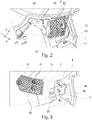
- the body and doors protection assembly 2 is arranged on a junction portion 9 of a vehicle body 7 (see Fig. 2 and Fig. 3 ), at which the A-pillar 5, the front door 4 and/or a rear edge 8 of the vehicle hood 3 join.
- the vehicle 1 comprises preferably two protection assemblies 2 at each junction portion 9 of the vehicle body 7.
- the body and doors protection assembly 2 comprises a first protecting member 10, a second protecting member 20 and a sliding member 30.
- the first protecting member 10, the second protecting member 20 and/or the sliding member 30 can be separately manufactured and they are individually arranged in the vehicle 1. Accordingly, each of the first protecting member 10, the second protecting member 20 and/or the sliding member 30 is individually replaceable if a repair is required.
- the body and doors protection assembly 2 is configured to protect the vehicle body 7 and its surrounding components such as front door 4, A-pillar 5 and front fender 6. In case of a collision, particularly if collision energy exceeds a predefined assembly tolerance of the vehicle hood 3, the vehicle hood 3 may be pushed in various directions. The body and doors protection assembly 2 stops a movement of the vehicle hood 3 in direction of a windshield of the vehicle 1 to avoid a windshield damage and to protect the front door 4 and/or the A-pillar 5. Further, the body and doors protection assembly 2 may relieve the collision energy via the sliding member 30 in a lateral direction X of the vehicle hood 3.
- the first protecting member 10 is attachable on an inner surface 33 of the vehicle hood 3 at the rear edge 8 of the vehicle hood 3 (see Fig. 1 ). As shown in Fig. 7 , the first protecting member 10 comprises three clamping elements 11 to fixedly attach the first protecting member 10 to the inner surface 33 of the vehicle hood 3.
- the second protecting member 20 comprises a base portion 21 and a cover portion 22 (see Fig. 4 and Fig. 5 ).
- the base portion 21 and the cover portion 22 are connected to each other by a fastening means 28.
- the fastening means comprises two clips 28a for fixing the base portion 21 and the cover portion 22 in a longitudinal direction Y of the vehicle body 7 and two pins 28b for fixing them in the lateral direction X relative to the vehicle hood 3.
- the base portion 21 of the second protecting member 20 comprises a guide 27, on which the sliding member 30 is movable.
- the second protecting member 20 is attachable at a front side portion 71 of the vehicle body 7 facing the rear edge 8 of the vehicle hood 3 in a closed position of the vehicle hood 3. As shown in Fig. 2 , the second protecting member 20 comprises two fixing elements 23 arrangeable at the front side portion 71 of the vehicle body 7 to fixedly attach the second protecting member 20 to the vehicle body 7.
- the front side portion 71 of the vehicle body 7 comprises a bracket 25, which may made of a metal material such as steel.
- the bracket 25 is integrally arranged at the front side portion 71 of the vehicle body 7 and comprise one or more bolts 26, which may be welded to the bracket 25.
- the base portion 21 of the second protecting member 20 is fixed at the bracket by means of corresponding nuts 26.
- the sliding member 30 is at least partially enclosed in the second protecting member 20.
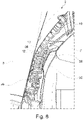
- the sliding member 30 is configured to contact the first protecting member 10 in the closed position of the vehicle hood 3 (see Fig. 4 and Fig. 8 ).
- the sliding member 30 is adjustable in the lateral direction X relative to the vehicle hood 3 along the guide 27 of the base portion 21 of the second protecting member 20.
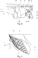
- Fig. 6 shows the sliding member 30 comprising a sliding body 31 and a shank 32.
- the sliding body 31 is connected to one end 37 of the shank 32 and adjustable with the shank 32.
- the sliding member 30 further comprises a nut 34 arranged through the shank 32.
- the nut 34 is configured to keep the sliding body 31 in position along the shank 32.
- the sliding member 30 comprises a lateral supporting portion 35 and a longitudinal supporting portion 36.
- the lateral supporting portion 35 is arranged substantially perpendicular to the shank 32 and configured to block a movement of the first protecting member 10 in the lateral direction X of the vehicle hood 3.
- the longitudinal supporting portion 36 is arranged substantially perpendicular to the lateral supporting portion 35 and configured to block the movement of the first protecting member 10 in the longitudinal direction Y of the vehicle body 7 in case of the displacement of the vehicle hood 3.
- Fig. 7 shows the first protecting member 10 comprising a lateral contacting portion 12 and a longitudinal contacting portion 13.
- the lateral contacting portion 12 can push the lateral supporting portion 35 of the sliding member 30 to steer out the collision energy via the sliding body.
- the longitudinal contacting portion 13 comes into contact with the longitudinal supporting portion 36 of the sliding member 30 to stop the movement of the vehicle hood 3 in the longitudinal direction Y (see also Fig. 8 ).
- the body and doors protection assembly 2 further comprises a seal protect member 24 arrangeable at the front side portion 71 of the vehicle body 7 and/or the junction portion 9 of the vehicle body.
- the seal protect member 24 surrounds at least partially the first protecting member 10, the second protecting member 20 and/or the sliding member 30 to additionally protect them in case of the displacement of the vehicle hood 3.
- the front fender 6 further comprises at least one mounting means 61 configured to fasten the body and doors protection assembly 2 additionally at the front fender 6 to insulate the front fender 6.
Landscapes
- Engineering & Computer Science (AREA)
- Chemical & Material Sciences (AREA)
- Combustion & Propulsion (AREA)
- Transportation (AREA)
- Mechanical Engineering (AREA)
- Superstructure Of Vehicle (AREA)
Abstract
Description
- The present disclosure relates to a body and doors protection assembly for a vehicle, a hood assembly comprising such a body and doors protection assembly, a vehicle comprising such a hood assembly and a manufacturing method for such a body and doors protection assembly.
- Conventionally, a hood of a motor vehicle is arranged to protect an engine compartment of the vehicle. In case of a collision, however, the hood may be folded, shoved or even invaded a front windshield, which may cause a severe damage on surrounding components such as the front windshield, front doors and/or an A-pillar. A subsequent repair or replacement of the hood and its surrounding components may be often complicated, which may increase repair costs.
- Hence, there may be a need to provide an improved a body and doors protection assembly for a vehicle, which limits a movement or deformation of a hood in case of a vehicle collision to protect its surrounding components.
- The problem is solved by the subject matters of the independent claims of the present disclosure, wherein further embodiments are incorporated in the dependent claims. It should be noted that the aspects of the disclosure described in the following apply to the body and doors protection assembly for a vehicle, the hood assembly comprising such a body and doors protection assembly, the vehicle comprising such a hood assembly and the manufacturing method for a body and doors protection assembly in a vehicle.
- According to the present disclosure, a body and doors protection assembly for a vehicle is presented. The body and doors protection assembly comprises a first protecting member, a second protecting member and a sliding member. The first first protecting member is attachable on an inner surface of a vehicle hood at a rear edge of the vehicle hood. The second protecting member is attachable in a front side portion of a vehicle body facing the rear edge of the vehicle hood in a closed position of the vehicle hood. The sliding member is at least partially enclosed in the second protecting member and configured to contact the first protecting member in the closed position of the vehicle hood. The sliding member is adjustable in a lateral direction relative to the vehicle hood in the closed position of the vehicle hood.
- The body and doors protection assembly may be configured to protect a vehicle body and vehicle doors in case of a collision of the vehicle. The body and doors protection assembly may stop a movement of the vehicle hood at the rear edge of the vehicle hood. Particularly, in case of a low-speed crash of the vehicle, the movement of vehicle hood in direction of a windshield may be effectively stopped so that no damage to a windshield, front doors and/or A-pillars may occur. In addition, the body and doors protection assembly may be easily adjustable for an optimal stop function after the vehicle hood is closed. Accordingly, the body and doors protection assembly may enable saving manufacturing time and costs.
- The body and doors protection assembly may be substantially divided into a first part and a second part. The first part may comprise the first protecting member, which may be fixedly attached on the inner surface of the vehicle hood facing a motor compartment of the vehicle. Preferably, the first protecting member may be arranged at the rear edge of the vehicle hood, wherein the rear edge of the vehicle hood may face a bottom portion of a front windshield of the vehicle. Accordingly, the rear edge of the vehicle hood may be arranged substantially perpendicular to a longitudinal direction of the vehicle body. The term "front" may refer to a forward direction of a vehicle in driving. Preferably, the first protecting member may be arranged on the inner surface of the vehicle hood at a lateral side of the rear edge relative to a longitudinal direction of the vehicle body.
- The second part may comprise the second protecting member and the sliding member. At least a part of the sliding member may be arranged inside the second protecting member. The second protecting member may be fixedly attached in the front side portion of the vehicle body. The vehicle body may be understood as a main supporting structure, i.e. chassis of the vehicle, to which all components of the vehicle may be attached. For instance, the vehicle hood may be pivotably mounted at a front portion of the vehicle body.
- The front side portion of the vehicle body may refer to a lateral side of the vehicle body at a front part of the vehicle body with respect to a forward driving direction of the vehicle. For instance, at the front side portion of the vehicle body, the front doors may be mounted. Hence, if the vehicle hood, which is mounted at the vehicle body, is closed, the rear edge of the vehicle hood may face the front side portion of the vehicle body. Consequently, in the closed position of the vehicle hood, the first protecting member and the second protecting member may face each other.
- In the closed position of the vehicle hood, the sliding member may come into contact with the first protecting member. Generally, in case of a vehicle collision, especially in case of a frontal collision, the vehicle hood may receive collision energy. If the collision energy is higher than an assembly tolerance of the vehicle hood at the vehicle body, the vehicle hood may be at least displaced and/or even damaged.
- In such a case, however, the sliding member may be adjusted by moving in the lateral direction, which is perpendicular relative to the longitudinal direction of the vehicle body. Accordingly, the sliding member may adjust a lateral displacement of the vehicle hood, even the assembly tolerance of the vehicle hood at the vehicle body is exceeded due to the collision. The assembly tolerance may be understood as a threshold of an assembled equipment, which may be a maximum mechanical stress exerted on the assembled equipment without any deformation or displacement of the assembled equipment.
- Accordingly, the sliding member may transfer stress exerted on the vehicle hood, for instance due to the collision, to the second protecting member. In other words, the stress, which is exerted on the vehicle hood and exceeds the assembly tolerance of the vehicle hood, may be discharged to the second protecting member via the sliding member. Hence, a damage risk of the vehicle hood due to a collision may be reduced.
- In an example, the sliding member comprises a sliding body and a shank. The sliding body is connected to one end of the shank and adjustable with the shank. The shank may comprise a first end and a second end. The first end of the shank may be connected to a first lateral surface of the sliding body and the second end of the shank may be adjacent to an outer lateral surface of the first protecting member, which may be arranged at an opposite side of the sliding body relative to the shank. Additionally, the second end of the shank may penetrate the outer lateral surface of the first protecting member and it may be connectable to the front side portion of the vehicle body.
- The sliding body may comprise the first lateral surface and a second lateral surface. The first lateral surface of the sliding body may be connected to the first end of the shank and the second lateral surface of the sliding body may contact the first protecting member in the closed position of the vehicle hood. The sliding body may shift its position outwardly in the lateral direction of the vehicle hood along the shank, to adjust a position of the vehicle hood in the lateral direction in case of the vehicle collision.
- In an example, the sliding member further comprises a nut arranged through the shank. The nut is configured to keep the sliding body in position along the shank. The nut may be a locking nut and/or a movable nut. In other words, the nut may be fixedly positioned on the shank such that in case of the lateral movement of the sliding body, preferably outwardly, the nut may limit the movement of the sliding body along the shank. Alternatively, the nut may be arranged movably along a longitudinal axis of the shank such that the sliding body may relieve the stress transferred from the first protecting member. Accordingly, the nut may allow the sliding body stay in position along the longitudinal axis of the shank.
- In an example, the sliding member comprises a lateral supporting portion. The lateral supporting portion is arranged at an opposite side of the shank relative to the sliding body and configured to block a movement of the first protecting member in the lateral direction of the vehicle hood. The lateral supporting portion may be integrally manufactured with the sliding body. Alternatively, the lateral supporting portion may be independently formed of the sliding body.
- The lateral supporting portion may be arranged at an opposite side of the shank relative to the sliding body, which is also connected to the sliding body. The lateral supporting portion may be arranged substantially perpendicular to the longitudinal axis of the shank. The term "substantially perpendicular" may be understood as an angle, which may be in a range of 45 to 135 degrees.
- The lateral supporting portion may directly contact the first protecting member in the closed position of the vehicle hood. Hence, the lateral supporting portion may be configured to effectively catch or support the movement of the first protecting member, particularly in the lateral direction of the vehicle hood in case of the displacement of the vehicle hood due to the collision.
- In an example, the sliding member further comprises a longitudinal supporting portion. The longitudinal supporting portion is arranged substantially perpendicular to the lateral supporting portion and configured to block the movement of the first protecting member in a longitudinal direction of the vehicle body.
- The longitudinal supporting portion may be integrally manufactured with the lateral supporting portion and/or the sliding body. Alternatively, the longitudinal supporting portion may be formed independently of the lateral supporting portion and/or the sliding body. The longitudinal supporting portion may be also arranged at an opposite side of the shank relative to the sliding body. The longitudinal supporting portion may be arranged substantially parallel to the longitudinal axis of the shank and/or to the rear edge of the vehicle hood.
- The longitudinal supporting portion may directly contact the first protecting member in the closed position of the vehicle hood. Hence, the longitudinal supporting portion may be configured to effectively catch or block the movement of the first protecting member, particularly in the longitudinal direction of the vehicle body in case of the displacement of the vehicle hood due to the collision. Accordingly, the vehicle hood may be prevented from being invaded in direction of the windshield, A-pillars and/or front doors of the vehicle.
- In an example, the first protecting member comprises at least one clamping element to fixedly attach the first protecting member to the inner surface of the vehicle hood. To fixedly hold the first protecting member at the vehicle hood, the first protecting member may comprise one or more clamping elements, which may be directly connected to the inner surface of the vehicle hood. The clamping element may comprise a clip means or a locking means. The first protecting member may be, hence, fixed at the inner surface of the vehicle hood without any guide pins and/or other fasteners. Alternatively, the first protecting member may be fixedly attached to the inner surface of the vehicle hood by adhesion, form-fitting means, force-fitting means, soldering, welding, etc.
- In an example, the second protecting member comprises a base portion and a cover portion. The base portion and the cover portion are connected to each other by a fastening means. The base portion of the second protecting member may be fixedly attached to the front side portion of the vehicle body, to which a front door of the vehicle may be mounted. The cover portion may be attached to the base portion may means of fasteners or clips. Alternatively, the cover portion may be mounted at the base portion by a hinge means. The second protecting member may at least partially enclose the sliding body and the shank of the sliding member between the base portion and the cover portion.
- In an example, the base portion of the second protecting member comprises a guide, on which the sliding member is movable. The guide may be formed stepless such that the sliding member, preferably the sliding body may slide smoothly on the guide. A surface of the guide contacting the sliding body may cause friction while moving the sliding body. Hence, the collision energy may be dissipated to overcome the friction between the guide and the sliding body and the guide may allow a controlled path of the vehicle hood.
- Accordingly, even though the base portion of the second protecting member may be arranged along a curved contour of front side portion of the vehicle body, the sliding body may be gradually pushed along the shank to avoid damage on surrounding components of the vehicle hood. In other words, a position of the sliding body inside the second protecting member may be adjusted without any bounce, despite the displacement of the vehicle hood due to the collision.
- In an example, the second protecting member comprises at least one fixing element arrangeable at the front side portion of the vehicle body to fixedly attach the second protecting member to the vehicle body. The second protecting member, preferably, the base portion may be fixed by means of one or more fixing elements at the front side portion of the vehicle body, at which a front door of the vehicle may be arranged.
- The front side portion of the vehicle body may comprise a bracket, which may made of a metal material such as steel. The bracket may be integrally arranged at the front side portion of the vehicle body and comprise one or more bolts, which may be welded to the bracket. The base portion may be fixed at the bracket by means of corresponding nuts. Alternatively, the base portion of the second protecting member may be fixedly attached to the front side portion of the vehicle body by adhesion, form-fitting means, force-fitting means, soldering, welding, etc.
- In an example, the body and doors protection assembly further comprises a seal protect member arrangeable at the front side portion of the vehicle body and at least partially surrounding the first protecting member, the second protecting member and/or the sliding member. The seal protect member may be configured to additionally protect the surrounding components of the vehicle hood such as the front door, A-pillar, windshield, etc. The seal protect member may be thus arranged between the front side portion of the vehicle body and the second protecting member and extends at least partially, preferably entirely over the first protecting member, the second protecting member and/or the sliding member in the closed position of the vehicle hood.
- In an example, the first protecting member, the second protecting member and/or the sliding member are individually replaceable in case of a damage. After the displacement of the vehicle hood due to the collision, first protecting member, the second protecting member and/or the sliding member may be also displaced or damaged. In such a case, the body and doors protection assembly may enable an easy repair of the body and doors protection assembly, since first protecting member, the second protecting member and the sliding member may be separately manufactured and individually arranged on the inner surface of the vehicle hood and at the front side portion of the vehicle body. After the repair, a new first protecting member, a new second protecting member and/or a new sliding member can be easily adapted to one another.
- In an example, the first protecting member, the second protecting member, the sliding member and/or the seal protect member may comprise a plastic material such as two components material including thermoplastic elastomer material, which may stretch to moderate elongations and return to its near original shape.
- According to the present disclosure, a hood assembly is presented. The hood assembly comprises a vehicle hood and a body and doors protection assembly as described above. A montage, repair and/or maintenance work of the hood assembly may be facilitated by arranging the body and doors protection assembly, which may be separately manufactured and individually arranged on an inner surface of the vehicle hood and at a front side portion of a vehicle body.
- According to the present disclosure, a vehicle is presented. The vehicle comprises a hood assembly as described above. In an example, a body and doors protection assembly is arranged on a junction portion of a vehicle body, at which an A-pillar, a front door and/or a rear edge of a vehicle hood join. The vehicle hood may be an overwrap type hood, which may be arranged directly adjacent to the A-pillar and the front door of the vehicle.
- In an example, each front side portion of the vehicle body, at which each front door of a driver side and a front passenger side may be mounted, may comprise the body and doors protection assembly. The body and doors protection assembly may stop or limit a movement of the vehicle hood and/or steer out collision energy to effectively protect the surrounding components. A controlled path of the vehicle hood during the collision may be ensured by adjusting a sliding member in a second protecting member with friction which dissipates the collision energy.
- According to the present disclosure, a manufacturing method for a body and doors protection assembly in a vehicle is presented. The manufacturing method comprises
- attaching a first protecting member on an inner surface of a vehicle hood at a rear edge of the vehicle hood,
- attaching a second protecting member in a front side portion of a vehicle body facing the rear edge of the vehicle hood, and
- establishing of contact the first protecting member and the second protecting member by a sliding member in a closed position of the vehicle hood.
- The sliding member is adjustable in a lateral direction relative to the vehicle hood.
- It should be noted that the above embodiments may be combined with each other irrespective of the aspect involved. Accordingly, the method may be combined with structural features and, likewise, the system may be combined with features described above with regard to the method.
- These and other aspects of the present embodiments will become apparent from and elucidated with reference to the embodiments described hereinafter in the closed position of the vehicle hood.
- Exemplary embodiments will be described in the following with reference to the following drawings.
- Fig. 1
- shows schematically and exemplarily an embodiment of a vehicle according to the present disclosure.
- Fig. 2 to Fig. 5
- show schematically and exemplarily an embodiment of a body and doors protection assembly according to the present disclosure.
- Fig. 6
- shows schematically and exemplarily an embodiment of a second protecting member and a sliding member according to the present disclosure.
- Fig. 7
- shows schematically and exemplarily an embodiment of a first protecting member according to the present disclosure.
- Fig. 8
- shows schematically and exemplarily an embodiment of a body and doors protection assembly according to the present disclosure.
-
Fig. 1 shows a vehicle 1 comprising avehicle hood 3 and a body anddoors protection assembly 2. Thevehicle hood 3 is an overwrap type hood, which may be arranged directly adjacent to an A-pillar 5 and afront door 4 of the vehicle 1. The body anddoors protection assembly 2 is arranged on ajunction portion 9 of a vehicle body 7 (seeFig. 2 and Fig. 3 ), at which the A-pillar 5, thefront door 4 and/or arear edge 8 of thevehicle hood 3 join. Hence, the vehicle 1 comprises preferably twoprotection assemblies 2 at eachjunction portion 9 of thevehicle body 7. - The body and
doors protection assembly 2 comprises a first protectingmember 10, a second protectingmember 20 and a slidingmember 30. The first protectingmember 10, the second protectingmember 20 and/or the slidingmember 30 can be separately manufactured and they are individually arranged in the vehicle 1. Accordingly, each of the first protectingmember 10, the second protectingmember 20 and/or the slidingmember 30 is individually replaceable if a repair is required. - The body and
doors protection assembly 2 is configured to protect thevehicle body 7 and its surrounding components such asfront door 4, A-pillar 5 andfront fender 6. In case of a collision, particularly if collision energy exceeds a predefined assembly tolerance of thevehicle hood 3, thevehicle hood 3 may be pushed in various directions. The body anddoors protection assembly 2 stops a movement of thevehicle hood 3 in direction of a windshield of the vehicle 1 to avoid a windshield damage and to protect thefront door 4 and/or the A-pillar 5. Further, the body anddoors protection assembly 2 may relieve the collision energy via the slidingmember 30 in a lateral direction X of thevehicle hood 3. - The first protecting
member 10 is attachable on aninner surface 33 of thevehicle hood 3 at therear edge 8 of the vehicle hood 3 (seeFig. 1 ). As shown inFig. 7 , the first protectingmember 10 comprises three clampingelements 11 to fixedly attach the first protectingmember 10 to theinner surface 33 of thevehicle hood 3. - The second protecting
member 20 comprises abase portion 21 and a cover portion 22 (seeFig. 4 and Fig. 5 ). Thebase portion 21 and the cover portion 22 are connected to each other by a fastening means 28. The fastening means comprises twoclips 28a for fixing thebase portion 21 and the cover portion 22 in a longitudinal direction Y of thevehicle body 7 and twopins 28b for fixing them in the lateral direction X relative to thevehicle hood 3. Thebase portion 21 of the second protectingmember 20 comprises aguide 27, on which the slidingmember 30 is movable. - The second protecting
member 20 is attachable at afront side portion 71 of thevehicle body 7 facing therear edge 8 of thevehicle hood 3 in a closed position of thevehicle hood 3. As shown inFig. 2 , the second protectingmember 20 comprises two fixingelements 23 arrangeable at thefront side portion 71 of thevehicle body 7 to fixedly attach the second protectingmember 20 to thevehicle body 7. - The
front side portion 71 of thevehicle body 7 comprises abracket 25, which may made of a metal material such as steel. Thebracket 25 is integrally arranged at thefront side portion 71 of thevehicle body 7 and comprise one ormore bolts 26, which may be welded to thebracket 25. Thebase portion 21 of the second protectingmember 20 is fixed at the bracket by means of corresponding nuts 26. - As shown in
Fig. 5 , the slidingmember 30 is at least partially enclosed in the second protectingmember 20. The slidingmember 30 is configured to contact the first protectingmember 10 in the closed position of the vehicle hood 3 (seeFig. 4 andFig. 8 ). The slidingmember 30 is adjustable in the lateral direction X relative to thevehicle hood 3 along theguide 27 of thebase portion 21 of the second protectingmember 20. -
Fig. 6 shows the slidingmember 30 comprising a slidingbody 31 and ashank 32. The slidingbody 31 is connected to oneend 37 of theshank 32 and adjustable with theshank 32. The slidingmember 30 further comprises anut 34 arranged through theshank 32. Thenut 34 is configured to keep the slidingbody 31 in position along theshank 32. - As shown in
Fig. 2 , the slidingmember 30 comprises alateral supporting portion 35 and a longitudinal supportingportion 36. Thelateral supporting portion 35 is arranged substantially perpendicular to theshank 32 and configured to block a movement of the first protectingmember 10 in the lateral direction X of thevehicle hood 3. The longitudinal supportingportion 36 is arranged substantially perpendicular to thelateral supporting portion 35 and configured to block the movement of the first protectingmember 10 in the longitudinal direction Y of thevehicle body 7 in case of the displacement of thevehicle hood 3. -
Fig. 7 shows the first protectingmember 10 comprising alateral contacting portion 12 and a longitudinal contactingportion 13. In case of a movement of thevehicle hood 3 in the lateral direction X of thevehicle hood 3, thelateral contacting portion 12 can push thelateral supporting portion 35 of the slidingmember 30 to steer out the collision energy via the sliding body. In case of a movement of thevehicle hood 3 in the longitudinal direction Y of thevehicle hood 3, the longitudinal contactingportion 13 comes into contact with the longitudinal supportingportion 36 of the slidingmember 30 to stop the movement of thevehicle hood 3 in the longitudinal direction Y (see alsoFig. 8 ). - The body and
doors protection assembly 2 further comprises a seal protectmember 24 arrangeable at thefront side portion 71 of thevehicle body 7 and/or thejunction portion 9 of the vehicle body. The seal protectmember 24 surrounds at least partially the first protectingmember 10, the second protectingmember 20 and/or the slidingmember 30 to additionally protect them in case of the displacement of thevehicle hood 3. - The
front fender 6 further comprises at least one mounting means 61 configured to fasten the body anddoors protection assembly 2 additionally at thefront fender 6 to insulate thefront fender 6. - It has to be noted that embodiments of the disclosure are described with reference to different subject matters. In particular, some embodiments are described with reference to method type claims whereas other embodiments are described with reference to the device type claims. However, a person skilled in the art will gather from the above and the following description that, unless otherwise notified, in addition to any combination of features belonging to one type of subject matter also any combination between features relating to different subject matters is considered to be disclosed with this application. However, all features can be combined providing synergetic effects that are more than the simple summation of the features.
- While the disclosure has been illustrated and described in detail in the drawings and description, such illustration and description are to be considered illustrative or exemplary and not restrictive. The disclosure is not limited to the disclosed embodiments. Other variations to the disclosed embodiments can be understood and effected by those skilled in the art in practicing a claimed disclosure, from a study of the drawings, the disclosure, and the dependent claims.
- In the claims, the word "comprising" does not exclude other elements or steps, and the indefinite article "a" or "an" does not exclude a plurality. A single processor or other unit may fulfil the functions of several items re-cited in the claims. The mere fact that certain measures are re-cited in mutually different dependent claims does not indicate that a combination of these measures cannot be used to advantage. Any reference signs in the claims should not be construed as limiting the scope.
Claims (15)
- A body and doors protection assembly (2) for a vehicle (1), comprising- a first protecting member (10),- a second protecting member (20), and- a sliding member (30),the first protecting member (10) being attachable on an inner surface (33) of a vehicle hood (3) at a rear edge (8) of the vehicle hood (3),
the second protecting member (20) being attachable in a front side portion (71) of a vehicle body (7) facing the rear edge (8) of the vehicle hood (3) in a closed position of the vehicle hood (3),
the sliding member (30) being at least partially enclosed in the second protecting member (20) and configured to contact the first protecting member (10) in the closed position of the vehicle hood (3), and
the sliding member (30) being adjustable in a lateral direction (X) relative to the vehicle hood (3) in the closed position of the vehicle hood (3). - The body and doors protection assembly (2) according to claim 1, the sliding member (30) comprising a sliding body (31) and a shank (32), the sliding body (31) being connected to one end of the shank (32) and adjustable with the shank (32).
- The body and doors protection assembly (2) according to claim 2, the sliding member (30) further comprising a nut arranged through the shank (32), the nut being configured to keep the sliding body (31) in position along the shank (32).
- The body and doors protection assembly (2) according to claim 2 or 3, the sliding member (30) comprising a lateral supporting portion (35), the lateral supporting portion (35) being arranged at an opposite side of the shank (32) relative to the sliding body (31) and configured to block a movement of the first protecting member (10) in the lateral direction (X) of the vehicle hood (3).
- The body and doors protection assembly (2) according to any of the preceding claims 2 to 4, the sliding member (30) further comprising a longitudinal supporting portion (36), the longitudinal supporting portion (36) being arranged substantially perpendicular to the lateral supporting portion (35) and configured to block the movement of the first protecting member (10) in a longitudinal direction of the vehicle body (7).
- The body and doors protection assembly (2) according to any of the preceding claims, the first protecting member (10) comprising at least one clamping element (11) to fixedly attach the first protecting member (10) to the inner surface (33) of the vehicle hood (3).
- The body and doors protection assembly (2) according to any of the preceding claims, the second protecting member (20) comprising a base portion (21) and a cover portion (22), the base portion (21) and the cover portion (22) being connected to each other by a fastening means (28).
- The body and doors protection assembly (2) according to any of the preceding claims, the base portion (21) of the second protecting member (20) comprising a guide (27), on which the sliding member (30) being movable.
- The body and doors protection assembly (2) according to any of the preceding claims, the second protecting member (20) comprising at least one fixing element (26) arrangeable at the front side portion (71) of the vehicle body (7) to fixedly attach the second protecting member (20) to the vehicle body (7).
- The body and doors protection assembly (2) according to any of the preceding claims, further comprising a seal protect member (24) arrangeable at the front side portion (71) of the vehicle body (7) and at least partially surrounding the first protecting member (10), the second protecting member (20) and/or the sliding member (30).
- The body and doors protection assembly (2) according to any of the preceding claims, the first protecting member (10), the second protecting member (20) and/or the sliding member (30) being individually replaceable in case of a damage.
- A hood assembly comprising a vehicle hood (3) and a body and doors protection assembly (2) according to any of the preceding claims 1 to 11.
- A vehicle (1) comprising a hood assembly according to the preceding claim 12.
- The vehicle (1) according to claim 13, a body and doors protection assembly (2) being arranged on a junction portion of a vehicle body (7), at which an A-pillar (5), a front door (4) and/or a rear edge (8) of a vehicle hood (3) join.
- Manufacturing method for a body and doors protection assembly (2) in a vehicle (1), comprising- attaching a first protecting member (10) on an inner surface (33) of a vehicle hood (3) at a rear edge (8) of the vehicle hood (3),- attaching a second protecting member (20) in a front side portion (71) of a vehicle body (7) facing the rear edge (8) of the vehicle hood (3), and- establishing the first protecting member (10) and the second protecting member (20) by a sliding member (30) in a closed position of the vehicle hood (3),the sliding member (30) being movable in a lateral direction (X) relative to the vehicle hood (3) in the closed position of the vehicle hood (3).
Priority Applications (3)
| Application Number | Priority Date | Filing Date | Title |
|---|---|---|---|
| EP21181081.7A EP4108548B1 (en) | 2021-06-23 | 2021-06-23 | A body and doors protection assembly for a vehicle |
| US17/807,968 US11801901B2 (en) | 2021-06-23 | 2022-06-21 | Body and doors protection assembly for a vehicle |
| CN202210719527.4A CN115503836B (en) | 2021-06-23 | 2022-06-23 | A body and door protection assembly for a vehicle |
Applications Claiming Priority (1)
| Application Number | Priority Date | Filing Date | Title |
|---|---|---|---|
| EP21181081.7A EP4108548B1 (en) | 2021-06-23 | 2021-06-23 | A body and doors protection assembly for a vehicle |
Publications (2)
| Publication Number | Publication Date |
|---|---|
| EP4108548A1 true EP4108548A1 (en) | 2022-12-28 |
| EP4108548B1 EP4108548B1 (en) | 2025-06-18 |
Family
ID=76584372
Family Applications (1)
| Application Number | Title | Priority Date | Filing Date |
|---|---|---|---|
| EP21181081.7A Active EP4108548B1 (en) | 2021-06-23 | 2021-06-23 | A body and doors protection assembly for a vehicle |
Country Status (3)
| Country | Link |
|---|---|
| US (1) | US11801901B2 (en) |
| EP (1) | EP4108548B1 (en) |
| CN (1) | CN115503836B (en) |
Families Citing this family (3)
| Publication number | Priority date | Publication date | Assignee | Title |
|---|---|---|---|---|
| USD1070684S1 (en) * | 2022-10-25 | 2025-04-15 | Bayerische Motoren Werke Aktiengesellschaft | Rear bumper for a vehicle |
| USD1057623S1 (en) * | 2023-04-05 | 2025-01-14 | GM Global Technology Operations LLC | Vehicle fender |
| USD1103045S1 (en) * | 2023-06-15 | 2025-11-25 | Hyundai Motor Company | Fender panel for automobile |
Citations (3)
| Publication number | Priority date | Publication date | Assignee | Title |
|---|---|---|---|---|
| US20060175115A1 (en) * | 2004-06-18 | 2006-08-10 | Mark Howard | Device for reducing the impact for pedestrians |
| US8899363B1 (en) * | 2013-07-24 | 2014-12-02 | Nissan North America, Inc. | Vehicle hood hinge structure |
| WO2020126599A1 (en) * | 2018-12-20 | 2020-06-25 | Renault S.A.S | Motor vehicle comprising an engine support and a chassis |
Family Cites Families (6)
| Publication number | Priority date | Publication date | Assignee | Title |
|---|---|---|---|---|
| FR2833658B1 (en) * | 2001-12-19 | 2004-12-03 | Plastic Omnium Cie | FIXING TO SUBJECT A PART TO A SUPPORT AND REFERENCE IT TO ITS ENVIRONMENT, IN PARTICULAR A MOTOR VEHICLE BODY PART |
| JP4486463B2 (en) * | 2004-09-30 | 2010-06-23 | 日本プラスト株式会社 | Non-occupant protection device |
| US7802345B2 (en) * | 2008-01-25 | 2010-09-28 | Chrysler Group Llc | Four-bar linkage hinge for a motor vehicle hood |
| FR2943028B1 (en) * | 2009-03-11 | 2011-04-29 | Peugeot Citroen Automobiles Sa | HOOD FOR AUTOMOTIVE WITHOUT HINGE OR LOCK |
| KR101982871B1 (en) * | 2013-12-02 | 2019-05-28 | 현대자동차주식회사 | Structure of cowl for vehicle |
| US9399443B2 (en) * | 2014-08-29 | 2016-07-26 | Ford Global Technologies, Llc. | Deployable vehicle hood extender for pedestrian protection |
-
2021
- 2021-06-23 EP EP21181081.7A patent/EP4108548B1/en active Active
-
2022
- 2022-06-21 US US17/807,968 patent/US11801901B2/en active Active
- 2022-06-23 CN CN202210719527.4A patent/CN115503836B/en active Active
Patent Citations (3)
| Publication number | Priority date | Publication date | Assignee | Title |
|---|---|---|---|---|
| US20060175115A1 (en) * | 2004-06-18 | 2006-08-10 | Mark Howard | Device for reducing the impact for pedestrians |
| US8899363B1 (en) * | 2013-07-24 | 2014-12-02 | Nissan North America, Inc. | Vehicle hood hinge structure |
| WO2020126599A1 (en) * | 2018-12-20 | 2020-06-25 | Renault S.A.S | Motor vehicle comprising an engine support and a chassis |
Also Published As
| Publication number | Publication date |
|---|---|
| CN115503836B (en) | 2025-07-01 |
| EP4108548B1 (en) | 2025-06-18 |
| US11801901B2 (en) | 2023-10-31 |
| CN115503836A (en) | 2022-12-23 |
| US20220410979A1 (en) | 2022-12-29 |
Similar Documents
| Publication | Publication Date | Title |
|---|---|---|
| US11801901B2 (en) | Body and doors protection assembly for a vehicle | |
| US9371093B1 (en) | Vehicles having upper side member reinforcement portions | |
| US6923474B2 (en) | Axle support for a front axle of a motor vehicle | |
| US7390038B2 (en) | Integrated bumper and upper fascia components of a motor vehicle | |
| EP3789238B1 (en) | An energy absorbing mounting structure | |
| US20130026791A1 (en) | Vehicle body structure | |
| US6926327B2 (en) | Side member and bumper beam attaching structure | |
| CN112758036A (en) | Slidable truss assembly for vehicle | |
| US10737568B2 (en) | Grille inner attachment structure | |
| US12280728B2 (en) | Arrangement for holding a sidewall element on a bodyshell part of a vehicle, bracket and vehicle | |
| US11198406B2 (en) | Grille shutter | |
| US20040130168A1 (en) | Front grille guard for vehicle | |
| US4877279A (en) | Stroking fascia for vehicle energy absorbing bumper systems | |
| CN109421821B (en) | Bottom cover assembly including bottom cover reinforcement member | |
| US9815497B1 (en) | Vehicles including an engine compartment spacer member | |
| US9440607B1 (en) | Energy diverting bumper structures for bumpers and methods of connecting energy diverting bumper structures | |
| CN119239775A (en) | Fender panel mounting device for vehicle body | |
| US20260048792A1 (en) | Front End for a Passenger Car | |
| US12325465B2 (en) | Front structure of vehicle | |
| KR101592116B1 (en) | Backpanel of rear bumper connection structure automobile | |
| CN108909676B (en) | Wiper subassembly for a motor vehicle | |
| US20260027989A1 (en) | Applique assembly for reducing pedestrian head impact injuries on the front end of a passenger car | |
| JP2020183155A (en) | Vehicle front part structure | |
| JP2527235B2 (en) | Bumper fascia mounting structure | |
| US20220185225A1 (en) | Energy absorbing member beneath vehicle hood |
Legal Events
| Date | Code | Title | Description |
|---|---|---|---|
| PUAI | Public reference made under article 153(3) epc to a published international application that has entered the european phase |
Free format text: ORIGINAL CODE: 0009012 |
|
| STAA | Information on the status of an ep patent application or granted ep patent |
Free format text: STATUS: REQUEST FOR EXAMINATION WAS MADE |
|
| 17P | Request for examination filed |
Effective date: 20220322 |
|
| AK | Designated contracting states |
Kind code of ref document: A1 Designated state(s): AL AT BE BG CH CY CZ DE DK EE ES FI FR GB GR HR HU IE IS IT LI LT LU LV MC MK MT NL NO PL PT RO RS SE SI SK SM TR |
|
| STAA | Information on the status of an ep patent application or granted ep patent |
Free format text: STATUS: EXAMINATION IS IN PROGRESS |
|
| 17Q | First examination report despatched |
Effective date: 20230502 |
|
| GRAP | Despatch of communication of intention to grant a patent |
Free format text: ORIGINAL CODE: EPIDOSNIGR1 |
|
| STAA | Information on the status of an ep patent application or granted ep patent |
Free format text: STATUS: GRANT OF PATENT IS INTENDED |
|
| INTG | Intention to grant announced |
Effective date: 20250220 |
|
| GRAS | Grant fee paid |
Free format text: ORIGINAL CODE: EPIDOSNIGR3 |
|
| GRAA | (expected) grant |
Free format text: ORIGINAL CODE: 0009210 |
|
| STAA | Information on the status of an ep patent application or granted ep patent |
Free format text: STATUS: THE PATENT HAS BEEN GRANTED |
|
| AK | Designated contracting states |
Kind code of ref document: B1 Designated state(s): AL AT BE BG CH CY CZ DE DK EE ES FI FR GB GR HR HU IE IS IT LI LT LU LV MC MK MT NL NO PL PT RO RS SE SI SK SM TR |
|
| REG | Reference to a national code |
Ref country code: GB Ref legal event code: FG4D |
|
| REG | Reference to a national code |
Ref country code: CH Ref legal event code: EP |
|
| REG | Reference to a national code |
Ref country code: DE Ref legal event code: R096 Ref document number: 602021032341 Country of ref document: DE |
|
| REG | Reference to a national code |
Ref country code: CH Ref legal event code: EP |
|
| P01 | Opt-out of the competence of the unified patent court (upc) registered |
Free format text: CASE NUMBER: APP_26724/2025 Effective date: 20250605 |
|
| REG | Reference to a national code |
Ref country code: IE Ref legal event code: FG4D |
|
| PGFP | Annual fee paid to national office [announced via postgrant information from national office to epo] |
Ref country code: AT Payment date: 20250721 Year of fee payment: 5 |
|
| PG25 | Lapsed in a contracting state [announced via postgrant information from national office to epo] |
Ref country code: FI Free format text: LAPSE BECAUSE OF FAILURE TO SUBMIT A TRANSLATION OF THE DESCRIPTION OR TO PAY THE FEE WITHIN THE PRESCRIBED TIME-LIMIT Effective date: 20250618 |
|
| PGFP | Annual fee paid to national office [announced via postgrant information from national office to epo] |
Ref country code: DE Payment date: 20250724 Year of fee payment: 5 |
|
| REG | Reference to a national code |
Ref country code: LT Ref legal event code: MG9D |
|
| PG25 | Lapsed in a contracting state [announced via postgrant information from national office to epo] |
Ref country code: GR Free format text: LAPSE BECAUSE OF FAILURE TO SUBMIT A TRANSLATION OF THE DESCRIPTION OR TO PAY THE FEE WITHIN THE PRESCRIBED TIME-LIMIT Effective date: 20250919 Ref country code: NO Free format text: LAPSE BECAUSE OF FAILURE TO SUBMIT A TRANSLATION OF THE DESCRIPTION OR TO PAY THE FEE WITHIN THE PRESCRIBED TIME-LIMIT Effective date: 20250918 |
|
| PG25 | Lapsed in a contracting state [announced via postgrant information from national office to epo] |
Ref country code: BG Free format text: LAPSE BECAUSE OF FAILURE TO SUBMIT A TRANSLATION OF THE DESCRIPTION OR TO PAY THE FEE WITHIN THE PRESCRIBED TIME-LIMIT Effective date: 20250618 |
|
| PGFP | Annual fee paid to national office [announced via postgrant information from national office to epo] |
Ref country code: GB Payment date: 20250725 Year of fee payment: 5 |
|
| PG25 | Lapsed in a contracting state [announced via postgrant information from national office to epo] |
Ref country code: HR Free format text: LAPSE BECAUSE OF FAILURE TO SUBMIT A TRANSLATION OF THE DESCRIPTION OR TO PAY THE FEE WITHIN THE PRESCRIBED TIME-LIMIT Effective date: 20250618 |
|
| PGFP | Annual fee paid to national office [announced via postgrant information from national office to epo] |
Ref country code: FR Payment date: 20250723 Year of fee payment: 5 |
|
| PG25 | Lapsed in a contracting state [announced via postgrant information from national office to epo] |
Ref country code: RS Free format text: LAPSE BECAUSE OF FAILURE TO SUBMIT A TRANSLATION OF THE DESCRIPTION OR TO PAY THE FEE WITHIN THE PRESCRIBED TIME-LIMIT Effective date: 20250918 |
|
| REG | Reference to a national code |
Ref country code: NL Ref legal event code: MP Effective date: 20250618 |
|
| PG25 | Lapsed in a contracting state [announced via postgrant information from national office to epo] |
Ref country code: LV Free format text: LAPSE BECAUSE OF FAILURE TO SUBMIT A TRANSLATION OF THE DESCRIPTION OR TO PAY THE FEE WITHIN THE PRESCRIBED TIME-LIMIT Effective date: 20250618 |
|
| PG25 | Lapsed in a contracting state [announced via postgrant information from national office to epo] |
Ref country code: NL Free format text: LAPSE BECAUSE OF FAILURE TO SUBMIT A TRANSLATION OF THE DESCRIPTION OR TO PAY THE FEE WITHIN THE PRESCRIBED TIME-LIMIT Effective date: 20250618 |
|
| PG25 | Lapsed in a contracting state [announced via postgrant information from national office to epo] |
Ref country code: PT Free format text: LAPSE BECAUSE OF FAILURE TO SUBMIT A TRANSLATION OF THE DESCRIPTION OR TO PAY THE FEE WITHIN THE PRESCRIBED TIME-LIMIT Effective date: 20251020 |
|
| REG | Reference to a national code |
Ref country code: AT Ref legal event code: MK05 Ref document number: 1803964 Country of ref document: AT Kind code of ref document: T Effective date: 20250618 |
|
| PG25 | Lapsed in a contracting state [announced via postgrant information from national office to epo] |
Ref country code: IS Free format text: LAPSE BECAUSE OF FAILURE TO SUBMIT A TRANSLATION OF THE DESCRIPTION OR TO PAY THE FEE WITHIN THE PRESCRIBED TIME-LIMIT Effective date: 20251018 |
|
| PG25 | Lapsed in a contracting state [announced via postgrant information from national office to epo] |
Ref country code: AT Free format text: LAPSE BECAUSE OF FAILURE TO SUBMIT A TRANSLATION OF THE DESCRIPTION OR TO PAY THE FEE WITHIN THE PRESCRIBED TIME-LIMIT Effective date: 20250618 Ref country code: SM Free format text: LAPSE BECAUSE OF FAILURE TO SUBMIT A TRANSLATION OF THE DESCRIPTION OR TO PAY THE FEE WITHIN THE PRESCRIBED TIME-LIMIT Effective date: 20250618 |
|
| PG25 | Lapsed in a contracting state [announced via postgrant information from national office to epo] |
Ref country code: CZ Free format text: LAPSE BECAUSE OF FAILURE TO SUBMIT A TRANSLATION OF THE DESCRIPTION OR TO PAY THE FEE WITHIN THE PRESCRIBED TIME-LIMIT Effective date: 20250618 |
|
| PG25 | Lapsed in a contracting state [announced via postgrant information from national office to epo] |
Ref country code: PL Free format text: LAPSE BECAUSE OF FAILURE TO SUBMIT A TRANSLATION OF THE DESCRIPTION OR TO PAY THE FEE WITHIN THE PRESCRIBED TIME-LIMIT Effective date: 20250618 |
|
| PG25 | Lapsed in a contracting state [announced via postgrant information from national office to epo] |
Ref country code: EE Free format text: LAPSE BECAUSE OF FAILURE TO SUBMIT A TRANSLATION OF THE DESCRIPTION OR TO PAY THE FEE WITHIN THE PRESCRIBED TIME-LIMIT Effective date: 20250618 |
|
| PG25 | Lapsed in a contracting state [announced via postgrant information from national office to epo] |
Ref country code: SK Free format text: LAPSE BECAUSE OF FAILURE TO SUBMIT A TRANSLATION OF THE DESCRIPTION OR TO PAY THE FEE WITHIN THE PRESCRIBED TIME-LIMIT Effective date: 20250618 |
|
| REG | Reference to a national code |
Ref country code: CH Ref legal event code: H13 Free format text: ST27 STATUS EVENT CODE: U-0-0-H10-H13 (AS PROVIDED BY THE NATIONAL OFFICE) Effective date: 20260127 |
|
| PG25 | Lapsed in a contracting state [announced via postgrant information from national office to epo] |
Ref country code: ES Free format text: LAPSE BECAUSE OF FAILURE TO SUBMIT A TRANSLATION OF THE DESCRIPTION OR TO PAY THE FEE WITHIN THE PRESCRIBED TIME-LIMIT Effective date: 20250618 |
|
| PG25 | Lapsed in a contracting state [announced via postgrant information from national office to epo] |
Ref country code: RO Free format text: LAPSE BECAUSE OF FAILURE TO SUBMIT A TRANSLATION OF THE DESCRIPTION OR TO PAY THE FEE WITHIN THE PRESCRIBED TIME-LIMIT Effective date: 20250618 |
|
| PG25 | Lapsed in a contracting state [announced via postgrant information from national office to epo] |
Ref country code: LU Free format text: LAPSE BECAUSE OF NON-PAYMENT OF DUE FEES Effective date: 20250623 |
|
| REG | Reference to a national code |
Ref country code: BE Ref legal event code: MM Effective date: 20250630 |
|
| REG | Reference to a national code |
Ref country code: DE Ref legal event code: R097 Ref document number: 602021032341 Country of ref document: DE |
|
| PG25 | Lapsed in a contracting state [announced via postgrant information from national office to epo] |
Ref country code: MC Free format text: LAPSE BECAUSE OF FAILURE TO SUBMIT A TRANSLATION OF THE DESCRIPTION OR TO PAY THE FEE WITHIN THE PRESCRIBED TIME-LIMIT Effective date: 20250618 |
|
| PG25 | Lapsed in a contracting state [announced via postgrant information from national office to epo] |
Ref country code: DK Free format text: LAPSE BECAUSE OF FAILURE TO SUBMIT A TRANSLATION OF THE DESCRIPTION OR TO PAY THE FEE WITHIN THE PRESCRIBED TIME-LIMIT Effective date: 20250618 Ref country code: IE Free format text: LAPSE BECAUSE OF NON-PAYMENT OF DUE FEES Effective date: 20250623 |
|
| PG25 | Lapsed in a contracting state [announced via postgrant information from national office to epo] |
Ref country code: IT Free format text: LAPSE BECAUSE OF FAILURE TO SUBMIT A TRANSLATION OF THE DESCRIPTION OR TO PAY THE FEE WITHIN THE PRESCRIBED TIME-LIMIT Effective date: 20250618 Ref country code: BE Free format text: LAPSE BECAUSE OF NON-PAYMENT OF DUE FEES Effective date: 20250630 |
|
| PG25 | Lapsed in a contracting state [announced via postgrant information from national office to epo] |
Ref country code: CH Free format text: LAPSE BECAUSE OF NON-PAYMENT OF DUE FEES Effective date: 20250630 |
|
| PLBE | No opposition filed within time limit |
Free format text: ORIGINAL CODE: 0009261 |
|
| STAA | Information on the status of an ep patent application or granted ep patent |
Free format text: STATUS: NO OPPOSITION FILED WITHIN TIME LIMIT |
|
| REG | Reference to a national code |
Ref country code: CH Ref legal event code: L10 Free format text: ST27 STATUS EVENT CODE: U-0-0-L10-L00 (AS PROVIDED BY THE NATIONAL OFFICE) Effective date: 20260430 |